WO2020021815A1 - Dispositif de capture de son - Google Patents
Dispositif de capture de son Download PDFInfo
- Publication number
- WO2020021815A1 WO2020021815A1 PCT/JP2019/018584 JP2019018584W WO2020021815A1 WO 2020021815 A1 WO2020021815 A1 WO 2020021815A1 JP 2019018584 W JP2019018584 W JP 2019018584W WO 2020021815 A1 WO2020021815 A1 WO 2020021815A1
- Authority
- WO
- WIPO (PCT)
- Prior art keywords
- sound
- sound pickup
- pickup device
- holding
- mounting
- Prior art date
- Legal status (The legal status is an assumption and is not a legal conclusion. Google has not performed a legal analysis and makes no representation as to the accuracy of the status listed.)
- Ceased
Links
Images











Classifications
-
- H—ELECTRICITY
- H04—ELECTRIC COMMUNICATION TECHNIQUE
- H04R—LOUDSPEAKERS, MICROPHONES, GRAMOPHONE PICK-UPS OR LIKE ACOUSTIC ELECTROMECHANICAL TRANSDUCERS; ELECTRIC HEARING AIDS; PUBLIC ADDRESS SYSTEMS
- H04R1/00—Details of transducers, loudspeakers or microphones
- H04R1/10—Earpieces; Attachments therefor ; Earphones; Monophonic headphones
- H04R1/105—Earpiece supports, e.g. ear hooks
-
- H—ELECTRICITY
- H04—ELECTRIC COMMUNICATION TECHNIQUE
- H04R—LOUDSPEAKERS, MICROPHONES, GRAMOPHONE PICK-UPS OR LIKE ACOUSTIC ELECTROMECHANICAL TRANSDUCERS; ELECTRIC HEARING AIDS; PUBLIC ADDRESS SYSTEMS
- H04R1/00—Details of transducers, loudspeakers or microphones
- H04R1/08—Mouthpieces; Microphones; Attachments therefor
-
- H—ELECTRICITY
- H04—ELECTRIC COMMUNICATION TECHNIQUE
- H04R—LOUDSPEAKERS, MICROPHONES, GRAMOPHONE PICK-UPS OR LIKE ACOUSTIC ELECTROMECHANICAL TRANSDUCERS; ELECTRIC HEARING AIDS; PUBLIC ADDRESS SYSTEMS
- H04R1/00—Details of transducers, loudspeakers or microphones
- H04R1/10—Earpieces; Attachments therefor ; Earphones; Monophonic headphones
- H04R1/1016—Earpieces of the intra-aural type
-
- H—ELECTRICITY
- H04—ELECTRIC COMMUNICATION TECHNIQUE
- H04R—LOUDSPEAKERS, MICROPHONES, GRAMOPHONE PICK-UPS OR LIKE ACOUSTIC ELECTROMECHANICAL TRANSDUCERS; ELECTRIC HEARING AIDS; PUBLIC ADDRESS SYSTEMS
- H04R1/00—Details of transducers, loudspeakers or microphones
- H04R1/10—Earpieces; Attachments therefor ; Earphones; Monophonic headphones
- H04R1/1058—Manufacture or assembly
- H04R1/1075—Mountings of transducers in earphones or headphones
-
- H—ELECTRICITY
- H04—ELECTRIC COMMUNICATION TECHNIQUE
- H04R—LOUDSPEAKERS, MICROPHONES, GRAMOPHONE PICK-UPS OR LIKE ACOUSTIC ELECTROMECHANICAL TRANSDUCERS; ELECTRIC HEARING AIDS; PUBLIC ADDRESS SYSTEMS
- H04R5/00—Stereophonic arrangements
- H04R5/027—Spatial or constructional arrangements of microphones, e.g. in dummy heads
-
- H—ELECTRICITY
- H04—ELECTRIC COMMUNICATION TECHNIQUE
- H04R—LOUDSPEAKERS, MICROPHONES, GRAMOPHONE PICK-UPS OR LIKE ACOUSTIC ELECTROMECHANICAL TRANSDUCERS; ELECTRIC HEARING AIDS; PUBLIC ADDRESS SYSTEMS
- H04R5/00—Stereophonic arrangements
- H04R5/033—Headphones for stereophonic communication
- H04R5/0335—Earpiece support, e.g. headbands or neckrests
-
- H—ELECTRICITY
- H04—ELECTRIC COMMUNICATION TECHNIQUE
- H04R—LOUDSPEAKERS, MICROPHONES, GRAMOPHONE PICK-UPS OR LIKE ACOUSTIC ELECTROMECHANICAL TRANSDUCERS; ELECTRIC HEARING AIDS; PUBLIC ADDRESS SYSTEMS
- H04R2460/00—Details of hearing devices, i.e. of ear- or headphones covered by H04R1/10 or H04R5/033 but not provided for in any of their subgroups, or of hearing aids covered by H04R25/00 but not provided for in any of its subgroups
- H04R2460/09—Non-occlusive ear tips, i.e. leaving the ear canal open, for both custom and non-custom tips
Definitions
- the present technology relates to a technical field of a sound pickup device used by being worn on a user's ear.
- Binaural recording is to record a sound close to the state of reaching the eardrum of each user in consideration of individual differences such as the shape of the head, body, and earlobe of each user.
- a head-related transfer function (Head-Related) that expresses changes in sound caused by the effects of diffraction and reflection due to each part of the human body such as the head, body, and earlobe of each user based on the binaurally recorded audio signal.
- Transfer @ Function HRTF
- Another application of the in-ear type sound collecting device is, for example, performing noise canceling in combination with a wearable sound output device such as an earphone or a headphone.
- Patent Documents 1 and 2 Some proposals have already been made for a technique for performing binaural recording using an in-ear type sound collecting device (for example, see Patent Documents 1 and 2).
- a sound collecting unit such as a microphone is arranged outside a user's external auditory canal, and a device main body holding the sound collecting unit almost completely fills the user's ear hole. It has a hermetically sealed structure.
- an object of the present technology is to provide a sound collection device in which sound input to a sound collection unit is performed favorably.
- a sound collecting device includes a mounting portion to which a sound collecting portion is attached and inserted into an external auditory canal, a holding portion inserted into the external auditory canal to hold the mounting portion at a predetermined position in the external auditory canal, A mounting part which is located on the opposite side of the mounting part with the part interposed therebetween and at least a part of which is engaged with the pinna, wherein the mounting part and the holding part do not block the external auditory meatus and have sound permeability. is there.
- the mounting portion to which the sound pickup portion is mounted and inserted into the external auditory canal and the holding portion for holding the mounting portion at a predetermined position in the external auditory canal are positioned so as not to block the external auditory canal with respect to the ear.
- the mounting portion be held hollow in the ear canal.
- the sound collection unit is located with the sound input hole opened at the entrance side of the ear canal.
- the sound collecting portion has the sound input hole located on the eardrum side with respect to the entrance of the ear canal.
- the attachment portion and the holding portion are formed integrally.
- the holding portion and the mounting portion are formed integrally.
- the attachment portion is formed of a linear material into a predetermined shape.
- the thickness of the attachment portion is small, and reflection and diffraction of sound waves by the attachment portion are unlikely to occur.
- the attachment portion is formed in a coil shape.
- the volume of the mounting portion is small, and reflection and diffraction of sound waves by the mounting portion are unlikely to occur.
- the sound pickup portion is located inside the mounting portion.
- the sound pickup section is held hollow in the ear canal, and does not contact the wall surface forming the ear canal.
- the sound collecting portion is detachably attached to the mounting portion.
- the sound pickup part can be exchanged with respect to the attachment part.
- the holding portion is formed in a predetermined shape from a linear material.
- the thickness of the holding portion is small, and reflection and diffraction of sound waves by the holding portion are unlikely to occur.
- the holding portion is formed in a coil shape.
- the holding portion is elastically deformable.
- the holding portion is formed in a shape such that the outer shape becomes smaller as approaching the attachment portion.
- the holding portion is inserted from the side having the smaller outer shape.
- the mounting portion is formed in a predetermined shape from a linear material.
- the thickness of the mounting portion is small, so that sound wave reflection and diffraction by the mounting portion are unlikely to occur.
- the mounting portion is provided with an inner engaging portion which is continuous with the holding portion and at least a part of which is engaged with the pinna, and the inner engaging portion has a coil shape. It is desirable to be formed.
- the mounting portion is provided with an inner engaging portion which is continuous with the holding portion and at least a part of which is engaged with the pinna. It is desirable that the inner engaging portion is located in the concha of the ear concha, so that the inner engaging portion can be elastically deformed in a direction of coming into contact with the portion.
- the inner engaging portion is positioned in the concha of the auricle while being pressed against a part of the auricle.
- the mounting portion is provided with an inner engaging portion which is continuous with the holding portion and at least a part of which is engaged with the auricle, and an outer diameter of the inner engaging portion. Is preferably larger than the diameter of the entrance of the ear canal.
- the mounting portion is provided with an outer engaging portion that is partially engaged with the back surface of the auricle.
- the sound pickup device is mounted on the ear by the inner engaging portion being engaged with a part of the auricle and the outer engaging portion being engaged with the back surface of the auricle.
- the outer engaging portion is provided with a pair of operating portions, and the outer engaging portion is elastically deformable in a direction in which the pair of operating portions is separated from and separated from each other. Is desirably pressed against the back of the pinna.
- the sound pickup device can be worn on the ear.
- the mounting portion to which the sound pickup portion is attached and inserted into the external auditory canal and the holding portion that holds the mounting portion at a predetermined position in the external auditory canal are located in a state where the external auditory canal is not closed to the ear, It is possible to provide a sound pickup device in which sound input to the sound pickup unit is performed favorably.
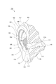
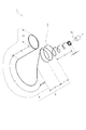
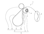
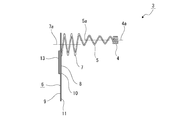
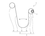
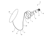
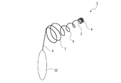
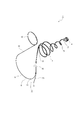
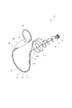
- FIGS. 2 to 35 show an embodiment of the sound pickup device according to the present technology, and are perspective views of ears to which the sound pickup device is attached. It is a perspective view of an ear which shows a part in cross section. It is a perspective view of a sound collection device. It is a side view of a sound collection device. It is a front view of a sound collection device. FIG. 3 is a perspective view showing a state in which the sound collecting device is attached to an ear with a part in section. It is a figure showing the state where a sound collection device is in the middle of being inserted in an external auditory canal. It is a figure showing the state where the sound collection device was worn on the ear.
- FIG. 11 is a diagram showing a first modification of the mounting portion. It is a figure showing the 2nd modification of an attachment part. It is a figure which shows the example fixed in the surface opposite to the surface in which the audio
- FIG. 4 is a perspective view showing an example in which a connection cord is located along the apparatus main body.
- Ears 100, 100 are part of the head 200, and are composed of the auricles 101, 101 and respective parts such as the eardrum, the semicircular canal, and the cochlea existing inside the head 200, respectively.
- the portions inside the pinna 101, 101 of the head 200 are the temporal portions 201, 201, respectively, and the pinna 101, 101 protrudes leftward or rightward from the temporal portion 201, 201, respectively.
- the pinna 101 is formed in a shallow concave shape that is opened substantially forward as a whole so as to have an inner space 150, and an outer peripheral portion is connected to a portion called an ear ring 102 and the ear ring 102 and is located near a temporal region 201. And a portion referred to as an annulus leg 103.
- a portion inside the ear ring 102 is referred to as a concave scaphoid 104, and a substantially lower half portion inside the scaphoid 104 is referred to as a convex anti-aural ring 105.
- a bifurcated convex portion continuing from the anti-ear ring 105, and the outer part and the inner part of the bifurcated part are the upper ear ring 106 and the upper ear ring, respectively. It is referred to as the lower leg 107.
- the portion between the upper ear ring 106 and the lower ear ring 107 is referred to as a concave triangular fossa 108, and the inner portion of the ear ring 105 and the lower ear ring 107 is referred to as a concave concha 109.
- the portion that continues below the anti-earring 105 is slightly bulged toward the temporal region 201 and is referred to as the antitragus 110.
- the portion on the side of the head 201 facing the antitragus 110 is referred to as an tragus 111 slightly bulged toward the antitragus 110, and the lower end continuous below the ear ring 102 is referred to as an earlobe 112. .
- An external ear hole 113a which is an entrance of the external auditory meatus 113, exists between the antitragus 110 and the tragus 111, and the external auditory meatus 113 communicates with the eardrum, the semicircular canal, and the like.
- the concha cavity 114 the space surrounded by the anti-ear ring 105, the anti-ear ring lower leg 107, and the ear ring leg 103, that is, the space on the front side of the concha boat 109 is referred to as the concha cavity 114, and
- the outer ear hole 113a is connected to the outer ear hole 113a.
- a space which is continuous with the lower side of the concha cavity 114 and opened in a U-shape in the inner space 150 is a space called an interbead notch 115.
- the external auditory canal 113 is a space surrounded by the wall surface 113 b, and the eardrum 116 exists behind the external auditory canal 113.
- the inner space 150 of the auricle 101 includes the concha cavity 114, the intertrabecular notch 115, and the space near the outer ear hole 113a of the external auditory meatus 113, the scaphoid 104, the ear ring 105, the upper leg 106, and the lower leg.
- the space also includes the space on the front side of the tragus 107, the triangular fossa 108, the antitragus 110 and the tragus 111.
- the sound collecting device 1 is composed of a sound collecting unit 2 for collecting sound and a device main body 3 to which the sound collecting unit 2 is attached (see FIGS. 3 to 5).
- the sound collection unit 2 is, for example, a small microphone, and has a sound input hole 2a for inputting sound.
- a voice is input to the sound collection unit 2 through the voice input hole 2a, for example, binaural recording is performed, and a head-related transfer function is measured based on the recorded voice signal.
- the apparatus main body 3 is composed of a mounting portion 4, a holding portion 5, and a mounting portion 6, and the mounting portion 4, the holding portion 5, and the mounting portion 6 are each formed into a predetermined shape by, for example, a linear (wire-shaped) metal material. Have been.
- the mounting portion 4, the holding portion 5, and the mounting portion 6 are integrally formed.
- the mounting portion 4, the holding portion 5, and the mounting portion 6 are formed of a metal material having a circular cross section, for example.
- the cross-sectional shape of the mounting portion 4, the holding portion 5, and the mounting portion 6 is not limited to a circular shape, and the outer shape in the cross-sectional shape is a curved surface from the viewpoint of preventing damage when the ear 100 is in contact.
- it is desirably formed in a circular shape, an elliptical shape, a long hole shape, or the like.
- the apparatus main body 3 is made of a metal material, high durability can be ensured.
- the device main body 3 may be formed of a material other than a metal material such as a resin material as long as high durability can be ensured, and a configuration in which the surface of a metal material such as a wire is covered with a resin. And so on.
- the mounting portion 4, the holding portion 5, and the mounting portion 6 are integrally formed as described above, the operation of connecting the mounting portion 4 and the holding portion 5 is not required, and the holding portion 5 and the mounting portion 6 can be connected. Since there is no need for an operation of coupling, it is possible to reduce the number of components in the sound pickup device 1 and the manufacturing cost.
- the mounting portion 4 and the holding portion 5 may be formed integrally and the holding portion 5 and the mounting portion 6 may be formed separately, and the mounting portion 4 and the holding portion 5 may be formed separately.
- the holding part 5 and the mounting part 6 which are formed may be integrally formed. Further, the mounting portion 4, the holding portion 5, and the mounting portion 6 may be formed separately from each other.
- the mounting portion 4 is formed in a coil shape, has an outer shape having the same size in the axial direction, and has, for example, no gap in the axial direction.
- the attachment section 4 has a function of attaching the sound pickup section 2, is inserted into the back of the ear canal 113 together with the sound pickup section 2, and is located near the eardrum 116 (see FIG. 6).
- the sound pickup unit 2 is attached to the inside of the attachment unit 4 (see FIGS. 3 to 5). Attachment of the sound pickup section 2 to the attachment section 4 may be performed by, for example, bonding or press fitting, or the sound pickup section 2 may be made detachable from the attachment section 4.
- the sound pickup section 2 Since the sound pickup section 2 is made detachable from the mounting section 4, the sound pickup section 2 can be exchanged with respect to the mounting section 4, so that the sound pickup section 2 can be always kept clean and sound pickup can be performed. The maintainability of the unit 2 can be improved. In addition, since the sound pickup unit 2 is detachably attached to the mounting unit 4, a sound pickup unit 2 of a type suitable for the intended use can be used.
- the holding portion 5 is formed in a coil shape having an outer diameter larger than the outer diameter of the mounting portion 4, and is provided continuously to one end of the mounting portion 4.
- the central axis 5a of the holding section 5 and the central axis 4a of the mounting section 4 are aligned.
- the center axis 5a of the holding section 5 and the center axis 4a of the mounting section 4 do not necessarily have to coincide with each other, as long as the mounting section 4 is positioned inside the holding section 5 with respect to the ear canal 113.
- the holding portion 5 has a gap in the axial direction, and is formed in a shape in which the outer shape becomes smaller as approaching the mounting portion 4.
- the holding section 5 has a function of holding the mounting section 4 and the sound collecting section 2 mounted on the mounting section 4, and is inserted into the external auditory canal 113 together with the mounting section 4 (see FIG. 6).
- the holding portion 5 is configured to be elastically deformable in the direction in which the central shaft 5a is bent. Therefore, since the holding portion 5 can be inserted into the external auditory canal 113 while sliding and deforming on the wall surface 113b forming the external ear canal 113 (see FIG. 7), the insertion of the mounting portion 4 and the holding portion 5 into the external ear canal 113 can be performed smoothly and smoothly. It can be done easily.
- the holding portion 5 is formed in a shape in which the outer shape becomes smaller as approaching the attachment portion 4. Therefore, when the mounting portion 4 and the holding portion 5 are inserted into the external auditory canal 113, the holding portion 5 is inserted from the smaller outer shape side, so that the mounting portion 4 and the holding portion 5 can be smoothly and easily inserted into the external ear canal 113. Can be done.
- the holding portion 5 is formed in a shape in which the outer shape becomes smaller as approaching the attachment portion 4, but is not formed in a shape with a sharp tip, so that the user inserts the holding portion 5 into the ear canal 113. In such a case, a sense of fear or the like hardly occurs, and a psychological burden can be suppressed.
- the mounting portion 4 that holds the sound pickup portion 2 is smaller than the outer diameter of the holding portion 5, the mounting portion 4 is easily held hollow in the external auditory canal 113, and the mounting portion 4 It is difficult to contact the wall surface 113b to be formed, and it is possible to accurately measure the head-related transfer function by the sound input to the external auditory canal 113 by the sound collection unit 2.
- the sound pickup unit 2 is mounted inside the mounting unit 4 in a state where the mounting unit 4 and the holding unit 5 are inserted into the external ear canal 113, the sound collecting unit 2 is held hollow in the external ear canal 113.
- the sound pickup unit 2 does not contact the wall surface 113b forming the external auditory canal 113, the head-related transfer function of the sound input to the external auditory canal 113 by the sound pickup unit 2 can be measured more accurately.
- the sound collecting portion 2 is positioned with the voice input hole 2 a opened on the external ear canal 113 side of the external ear canal 113.
- the head-related transfer function of the sound input to the external ear canal 113 can be measured more accurately.
- the sound input unit 2 has the sound input hole 2 a located on the eardrum 116 side with respect to the external ear hole 113 a of the external auditory canal 113, the sound input to the external ear canal 113 is reliably input to the sound collecting unit 2.
- the head-related transfer function based on the sound input to the ear canal 113 can be measured more accurately.
- the mounting portion 6 is configured such that an inner engaging portion 7, an intermediate portion 8, and an outer engaging portion 9 are successively arranged in order (see FIGS. 3 to 5).
- the inner engaging portion 7 is formed in a coil shape having an outer diameter larger than the outer diameter of the holding portion 5, and is provided continuously to one end of the holding portion 5.
- the inner engaging portion 7 has an outer shape having the same size in the axial direction, and the central shaft 7a is biased in a direction orthogonal to the central axis 5a of the mounting portion 6 and the central axis 4a of the holding portion 5 in the axial direction. Is located.
- the mounting portion 6 has a gap in the axial direction.
- the inner engaging portion 7 is a portion that is engaged with and attached to a part of the pinna 101, and has an outer diameter larger than the diameter of the external ear hole 113 a in the external auditory canal 113.
- the inner engaging portion 7 is configured to be elastically deformable in an axial direction that is a direction in which the inner engaging portion 7 comes into contact with and separates from the holding portion 5.
- the inner engaging portion 7 is inserted into the concha cavity 114 with the sound collecting portion 2, the mounting portion 4 and the holding portion 5 inserted into the external auditory canal 113 (see FIG. 6).
- the inner engaging portion 7 is in a state where the end surface on the mounting portion 4 side in the axial direction is in contact with the inner surface forming the concha cavity 114 and is slightly compressed in the axial direction and is opposite to the mounting portion 4.
- Each part of the side surface is pressed against the tragus 111 or the antitragus 110 from the external auditory canal 113 side by elasticity.
- the inner engaging portion 7 is elastically deformable in a direction of coming and going from the holding portion 5, and is located in the concha region 114.
- each of the inner engaging portions 7 is pressed against the tragus 111 or the antitragus 110 from the external auditory canal 113 side and positioned in the concha concha 114, so that the inner engaging portion 7 Is stably engaged with and attached to the auricle 101, and the position of the sound pickup unit 2 with respect to the external auditory canal 113 can be stabilized.
- the mounting portion 4 and the holding portion 5 and the inner engaging portion 7 are in a positional relationship according to the relative positions of the external auditory canal 113 and the concha cavity 114.
- the mounting portion 4 and the holding portion 5 can be smoothly and easily inserted into the external auditory canal 113, and the inner engaging portion 7 can be smoothly and easily inserted into the concha cavity 114 and attached to the pinna 101. it can.
- the inner engaging portion 7 is larger than the diameter of the outer ear hole 113 a of the outer ear canal 113, the inner engaging portion 7 is not inserted into the outer ear canal 113, and thus the sound collecting device 1 with respect to the ear 100. A stable mounting state can be ensured, and the position of the sound pickup unit 2 with respect to the external auditory canal 113 can be stabilized.
- the intermediate portion 8 is formed in a straight line and is provided continuously to one end of the inner engaging portion 7.
- the intermediate portion 8 is led out from the interbead notch 115 to the front side of the auricle 101 when the inner engaging portion 7 is located in the concha cavity 114, and is located in front of the lower end portion of the auricle 101.
- the intermediate portion 8 is formed in a linear shape slightly inclined with respect to the up and down direction, and the upper end portion is closer to the temporal portion 201 than the lower end portion in a state where the inner engagement portion 7 is inserted into the concha cavity 114. It is inclined in the direction to be.
- the middle portion 8 is led out of the interbead notch 115 and is located in front of the lower end portion of the pinna 101, as described above, the upper end portion is located closer to the temporal portion 201 than the lower end portion. Is formed so as to be hard to interfere with the lower end portion of the pinna 101, to prevent the positions of the inner engaging portion 7 and the holding portion 5 from being changed easily, The position with respect to 113 can be stabilized.
- the intermediate portion 8 may be formed in a linear shape that is bent into a convex shape that is substantially forward (see the circle in FIG. 4). Even when the intermediate portion 8 is formed in a linear shape bent in a mountain shape, the intermediate portion 8 is less likely to interfere with the lower end portion of the pinna 101, and the positions of the inner engaging portion 7 and the holding portion 5 are changed. The position of the sound pickup unit 2 with respect to the external auditory canal 113 can be stabilized.
- the outer engaging portion 9 is provided continuously to one end of the intermediate portion 8 (see FIGS. 3 to 5).
- the outer engaging portion 9 includes a first operating portion 10 continuous with the intermediate portion 8, an intermediate connecting portion 11 continuous with the first operating portion 10, a second operating portion 12 continuous with the intermediate connecting portion 11, and a second operating portion 12.
- the end portion 13 is continuous with the action portion 12.
- the first action section 10 is formed in a straight line extending substantially in the vertical direction.
- the intermediate connecting portion 11 is located at the lowest position in the outer engaging portion 9 and is formed in an arc shape in which the axial direction is substantially the left-right direction.
- the second action portion 12 is located on the rear side of the middle portion 8 and the first action portion 10 and is formed in a straight line approaching the middle portion 8 as going upward.
- the upper end of the second acting portion 12 is located closest to the continuous portion of the inner engaging portion 7 and the intermediate portion 8.
- the end portion 13 is formed in a circular shape whose axial direction is substantially in the left-right direction.
- the first engaging portion 10 When the inner engaging portion 7 is located in the concha cavity 114, the first engaging portion 10 is located below the front side of the auricle 101, and the intermediate connecting portion 11 is connected to the outer engaging portion 9.
- the second operating portion 12 and the terminal portion 13 are located below the auricle 101 below the auricle 101 (see FIG. 6). At this time, the upper end of the second acting portion 12 of the outer engaging portion 9 is engaged with a root portion on the back surface of the pinna 101 (see FIG. 8).
- the inner engaging portion 7 is engaged with a part of the pinna 101 and the second operating portion 12 is engaged with the root portion on the back surface of the pinna 101. Accordingly, the sound pickup device 1 can be easily and stably mounted on the ear 100.
- the outer engaging portion 9 is configured to be elastically deformable in a direction in which the first operating portion 10 and the second operating portion 12 are separated from each other. Therefore, when the sound pickup device 1 is attached to the ear 100, the first engagement portion 10 and the second engagement portion 12 are elastically deformed so as to be separated from each other, and the outer engagement portion 9 is opened (FIG. 9). Reference), the auricle 101 is inserted between the first action portion 10 and the second action portion 12 of the open outer engagement portion 9, so that the sound pickup device 1 can be easily attached to the ear 100. be able to.
- the sound pickup device 1 is attached to the pinna 101 in a state where the second action section 12 is elastically pressed against the back surface of the pinna 101, the sound pickup device 1 is unlikely to fall off from the ear 100, so that the sound pickup device 1 can be collected. An easy and stable mounting state of the sound device 1 to the ear 100 can be ensured.
- the mounting part 4 and the holding part 5 are connected to the external auditory canal 113. And has sound permeability without blocking.
- the mounting portion 4 to which the sound pickup portion 2 is mounted and inserted into the external auditory canal 113 and the holding portion 5 for holding the mounting portion 4 at a predetermined position of the external auditory canal 113 are positioned with respect to the ear 100 without closing the external auditory canal 113. Therefore, it is possible to provide the sound collecting device 1 in which the propagation of the sound wave toward the sound collecting unit 2 is not easily disturbed, and the sound input to the sound collecting unit 2 is performed well.
- the sound pickup device 1 can be mounted in the mounted state.
- the sound pickup device 1 is hardly displaced from the ear 100, and a stable mounting state of the sound pickup device 1 on the ear 100 can be ensured.
- the inner engaging portion 7 that is continuous with the attachment portion 4 and the holding portion 5 having a certain length is held in the concha cavity 114, when the sound collection device 1 is repeatedly attached to the ear 100, Also, the position of the sound pickup unit 2 held by the mounting unit 4 with respect to the eardrum 116 is always constant, high reproducibility of the position of the sound pickup unit 2 with respect to the eardrum 116 is ensured, and the reliability of measured values is improved. Can be. Note that the sound pickup device 1 is attached to both the left ear 100 and the right ear 100, and the positions of the sound pickup units 2, 2 with respect to the eardrums 116, 116 are always constant in the left and right ears 100, 100. It is possible.
- the mounting portion 4 and the sound collecting portion 2 are so long that the mounting portion 4 and the sound collecting portion 2 do not contact the eardrum 116 when the mounting portion 4 and the sound collecting portion 2 are inserted into the ear canal 113, the mounting portion 4 and the sound collecting portion 2 are separated from each other.
- the tympanic membrane 116 can be protected without contacting the same.
- the mounting part 4, the holding part 5, and the mounting part 6 are all formed in a predetermined shape from a linear material, the thickness of the mounting part 4, the holding part 5, and the mounting part 6 is thin, and Since the volume is small, reflection and diffraction of sound waves by the mounting portion 4, the holding portion 5 and the mounting portion 6 are unlikely to occur, and a good input state of sound to the sound collecting portion 2 can be secured.
- the mounting portion 4, the holding portion 5, and the inner engaging portion 7 are all formed in a coil shape, the volumes of the mounting portion 4, the holding portion 5, and the inner engaging portion 7 are small, and the mounting portion 4 Reflection and diffraction of the sound wave by the holding portion 5 and the inner engaging portion 7 are more unlikely to occur, and a more favorable input state of the sound to the sound pickup portion 2 can be secured.
- the mounting portion 4 and the holding portion 5 to be inserted into the ear canal 113 are formed in a coil shape and the outer peripheral surface in the cross-sectional shape is formed in a curved shape, the mounting portion 4 and the holding portion 5 may be in contact with the wall surface 113b of the ear canal 113. This can also prevent the wall surface 113b from being damaged.
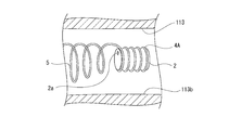
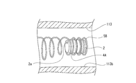
- the mounting portion 4A according to the first modified example is formed in a coil shape with a gap between each portion in the axial direction, and is wound around the sound pickup portion 2 (see FIG. 10).
- the sound pickup section 2 is held by being wound around the mounting section 4A, and is replaceable with respect to the mounting section 4A. Since the sound pickup unit 2 can be held by winding the attachment unit 4A, the sound pickup unit 2 can be easily held.
- a spiral groove may be formed on the outer peripheral surface of the sound pickup unit 2, and the mounting portion 4A may be wound around the spiral groove.
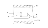
- the mounting portion 4B according to the second modification is formed in a straight line, and is fixed to a part of the sound collecting portion 2 by, for example, bonding (see FIG. 11). Since the mounting portion 4B is formed in a straight line, its weight is reduced, so that the sound pickup device 1 is reduced in weight, and when the sound pickup device 1 is mounted on the ear 100, the load on the ear 100 is small and a good feeling of wearing is achieved. Is secured.
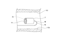
- the mounting portion 4B is fixed to the surface opposite to the surface on which the sound input hole 2a is formed, the sound input hole 2a of the sound collecting portion 2 faces the outer ear hole 113a. Good (see FIG. 12). Since the mounting portion 4B is fixed to the surface of the sound collection portion 2 opposite to the surface on which the voice input hole 2a is formed, the voice input hole 2a is not closed by the mounting portion 4B, and the sound collection portion 2B can be collected. A favorable input state of the sound to the sound unit 2 can be ensured.
- the mounting portion 4B When the mounting portion 4B is fixed to the surface opposite to the surface on which the sound input hole 2a of the sound collecting portion 2 is formed, the mounting portion 4B is bent so that a part of the mounting portion 4B is folded. It is desirable that the bent portion 4b be bent in a curved shape, for example, a semicircular arc shape. By bending the bent portion 4b of the mounting portion 4B in a curved shape, the wall surface 113b of the external auditory canal 113 can be protected. Further, a cushioning material may be attached to the bent portion 4b to prevent the contact between the wall surface 113b of the external auditory canal 113 and the bent portion 4b to protect the wall surface 113b.
- a filter 14 may be attached to the surface of the sound pickup unit 2 where the sound input hole 2a is formed (see FIG. 13). By mounting the filter 14 on the surface of the sound pickup unit 2 where the sound input hole 2a is formed, foreign matter such as earwax and the like can be prevented from entering the sound pickup unit 2 from the sound input hole 2a, and accurate measurement results can be obtained. Obtainable.
- the configuration in which the filter 14 is attached to the sound collection unit 2 can also be used in a configuration in which the sound collection unit 2 is protected by the mounting units 4 and 4A.
- the holding portion 5A according to the first modification is formed in a mesh shape, and is formed in a cylindrical shape, for example, a cylindrical shape (see FIG. 14). Attachment portion 4A is continuous with the end on the back side of holding portion 5A, and attachment portion 4A is located, for example, inside holding portion 5A.
- a mesh shape can be formed of, for example, a resin material such as polypropylene or polyethylene or a thin metal material.
- the holding portion 5A may be formed of a shape memory alloy.
- the holding portion 5B according to the second modification is formed in a coil shape and has the same diameter in the axial direction (see FIG. 15). Attachment portion 4A is continuous with the end on the back side of holding portion 5B, and attachment portion 4A is located inside holding portion 5B. Note that the holding portion 5B shown in FIG. 15 has the same diameter in the axial direction, but the holding portion 5B does not need to have the same diameter. For example, the holding portion 5B has a shape in which the diameter increases toward the outer ear hole 113a. There may be.
- the sound collecting portion 2 Since the mounting portion 4A is located inside the holding portion 5B, the sound collecting portion 2 is held hollow in the external auditory canal 113, and the head-related transfer function by the sound input to the external auditory canal 113 by the sound collecting portion 2 is accurately measured. can do.
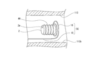
- the holding portion 5C according to the third modified example is constituted by a straight portion 15 and an annular portion 16 connected to an end on the far side of the straight portion 15 (see FIG. 16).
- the annular portion 16 is formed, for example, in an annular shape.
- the mounting portion 4A is continuous with the annular portion 16 of the holding portion 5C, and the outer diameter of the annular portion 16 is larger than the outer diameter of the mounting portion 4A.
- the sound pickup portion 2 is held hollow in the external auditory canal 113, and the sound input by the sound input portion 2 to the external auditory canal 113 is generated.
- the head-related transfer function can be measured accurately.
- the holding portion 5C is constituted by the straight portion 15 and the annular portion 16 and is small in weight, the sound pickup device 1 is reduced in weight, and a good wearing feeling is secured when the sound pickup device 1 is attached to the ear 100. You.
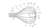
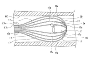
- a plurality of elastically deformable linear members 17, 17,... are arranged in the circumferential direction, and are formed in a shape such as a whisk or a tea whisk, for example.
- the intermediate portion 17a is formed so as to bulge outward, and the ends 17b and 17c on both sides are narrowed (see FIGS. 17 and 18).
- a mounting portion 4A is continuous with the rear end 17c of the holding portion 5D, and the mounting portion 4A is located, for example, inside the holding portion 5D.
- the intermediate portion 17a In a state before the holding portion 5D is inserted into the external auditory canal 113, the intermediate portion 17a is swelled outward at the maximum size (see FIG. 17).
- the intermediate portion 17a slides on the wall surface 113b, and is elastically deformed by the force received from the wall surface 113b so that the intermediate portion 17a is slightly narrowed, so that the overall length becomes slightly longer (FIG. 18). reference).
- the use of the holding portion 5D whose outer shape is changed in this way allows the holding portion 5D to be inserted regardless of the size of the ear canal 113, so that the sound collection portion 2 regardless of the size of the ear canal 113 between individuals. Can be reliably inserted into the ear canal 113. Further, since the mounting portion 4A is located inside the holding portion 5D, the sound pickup portion 2 is held hollow in the external auditory canal 113, and the head-related transfer function by the sound input to the external auditory canal 113 by the sound pickup portion 2 can be accurately determined. Can be measured.
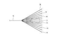
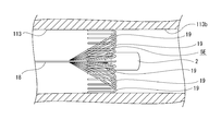
- the holding portion 5E according to the fifth modified example includes one first linear member 18 and a plurality of second linear members 19, 19,. One end of each of 19,... Is coupled to the rear end of the first linear member 18 (see FIGS. 19 and 20).
- the second linear members 19, 19,... are positioned so as to be displaced toward the outer peripheral side as the distance from the first linear member 18 increases.
- the second linear members 19 are elastically deformable.
- Attaching portion 4A is continuous with the inner end of the first linear member 18, and the attaching portion 4A is located, for example, inside the second linear members 19, 19,.
- the second linear members 19, 19,... are linear (see FIG. 19).
- the second linear members 19, 19,... Slide on the wall surface 113b, and the second linear members 19, 19,. Is elastically deformed so as to be folded outward (see FIG. 20).
- the second linear members 19, 19,... May be curved in a U-shape, not a straight end. Thereby, the contact with the skin can be made softer when the holder 5E is inserted into the external auditory canal 113.
- the holding portion 5E By using the holding portion 5E whose outer shape is changed in this way, the holding portion 5E is inserted irrespective of the size of the ear canal 113, so that the sound collection portion 2 is provided regardless of the size of the ear canal 113 between individuals. Can be reliably inserted into the ear canal 113.
- the mounting portion 4A since the mounting portion 4A is located inside the holding portion 5E, the sound pickup portion 2 is held hollow in the external auditory canal 113, and the head-related transfer function by sound input to the external auditory canal 113 by the sound pickup portion 2 can be accurately determined. Can be measured.
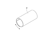
- the holding portion 5F according to the sixth modification is formed of a sheet-like material (see FIG. 21).
- the attachment portion is not shown, but the holding portion 5F is configured to use a force that increases the diameter when the force of the rounded sheet is removed. Accordingly, the holding portion 5F is inserted into the external auditory canal 113 in a state where the diameter is small and rounded.
- the diameter is widened and is in contact with the wall surface 113b.
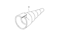
- the holding portion 5G according to the seventh modification is formed of a bag-shaped deformable material (see FIG. 22).
- the attachment portion is not shown, but the holding portion 5G exerts a force such that it is deformed into a planar shape when air is sealed in a bag-shaped member at least partially formed in a spiral shape. It is configured to use. Therefore, the holding portion 5G is inserted into the external auditory canal 113 in a state where the diameter is small and rounded.
- expansion or contraction is performed by heat. It is also possible to use a holding part having a configuration formed of a material having a high thermal expansion property.
- the holding portion may be formed in a band shape or a corrugated plate shape. Also in this case, the holding portion may be elastically deformable.
- the inner engaging portion 7A according to the modified example is constituted by the main body 20 and the hook 21 (see FIG. 23).
- the main body 20 is not limited to a coil shape, and may have another shape, for example, a cylindrical shape.
- the main body 20 is inserted into the concha cavity 114.
- the hook 21 protrudes from the upper end of the main body 20 and is formed, for example, in a linear or curved shaft shape.
- the tip of the hook 21 is inserted into the concha 109 and the tip is engaged with a part of the pinna 101.
- the hook 21 is inserted into the concha boat 109 and is engaged with a part of the pinna 101 when the main body 20 is inserted into the concha cavity 114, so that the inner engaging portion 7 In this case, the sound pickup device 1 does not shift with respect to the ear 100, and a stable wearing state of the sound pickup device 1 with respect to the ear 100 can be ensured.
- the inner engaging portion may be formed in a mesh shape from a resin material such as polypropylene or polyethylene or a thin metal material, similarly to the holding portion 5A, or may be formed from a shape memory alloy. Further, the inner engaging portion may be formed in a band-like or corrugated plate shape similarly to the holding portion, and in this case, may be elastically deformable.
- the inner engaging portion can be selected according to the shape and size of the pinna 101 of each individual and the shape of the fold of the pinna 101, and can be used by replacing the holding portion 5 for each individual. It may be so.
- the outer engaging portion 9A according to the first modified example is provided with an adhesive portion 22 instead of the second acting portion 12 and the terminal portion 13 (see FIG. 24).
- the adhesive portion 22 is formed in a sheet shape, for example, and is attached to the back surface of the pinna 101.
- the adhesive section 22 has an adhesive property that allows the adhesive section 22 to be repeatedly attached to and removed from the pinna 101.
- the sound pickup device 1 can be attached to the ear 100 by attaching the adhesive portion 22 to the outer engagement portion 9A in this manner, the sound pickup device 1 can be easily and quickly attached to the ear 100. be able to.
- the adhesive portion 22 is attached to the pinna 101, the entire sound collecting device 1 is less likely to be displaced with respect to the ear 100, and the displacement of the sound collecting portion 2 can be prevented.
- the outer engaging portion 9B according to the second modified example is constituted by the adhesive portion 22 (see FIG. 25).
- the adhesive portion 22 is attached to a chin, a temple, or the like.
- the outer engaging portion 9B can be attached by attaching the adhesive portion 22 as described above, the sound collecting device 1 can be easily and quickly attached to the ear 100. In addition, since the adhesive portion 22 is attached to the pinna 101, the entire sound collecting device 1 is less likely to be displaced with respect to the ear 100, and the displacement of the sound collecting portion 2 can be prevented. Further, since the outer engaging portion 9B is formed only of the adhesive portion 22, the sound pickup device 1 can be reduced in size and weight. Further, the outer engagement portion 9B may be formed in a shape along the auricle 101 or the face. This can prevent the sound pickup unit 2 from being displaced.
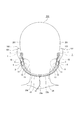
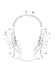
- connection mode for connecting the sound collection device 1 for the left ear and the sound collection device 1 for the right ear will be described (see FIGS. 26 to 29).
- a connection cord 23 that electrically connects the sound pickup units 2 and 2 and a connection member 24 that mechanically connects the device main bodies 3 and 3 are used.
- connection cord 23 has a connection portion 23a connected to various devices and the like and branch portions 23b and 23b branched for the left and right with respect to the connection portion 23a, and one end of each of the branch portions 23b and 23b is They are connected to the sound pickup units 2 and 2 respectively.
- connection cord 23 has the branch portions 23b, 23b located on the rear side below the occipital region, and the connection member 24 extends along the branch portions 23b, 23b of the connection cord 23, on the rear side below the occipital region. (See FIG. 26). Both ends of the connection member 24 are connected to, for example, the intermediate connection portions 11 and 11. In addition, the part where both of the connection cord 23 and the connection member 24 are located along may be located in the joined state.
- the sound pickup devices 1 and 1 are connected by the connecting member 24, the sound pickup devices 1 and 1 are hardly displaced with respect to the ears 100 and 100, respectively. Can be prevented. In addition, since the left and right device main bodies 3 and 3 are connected by the connection member 24, it is also useful to prevent one of the sound collection devices 1 from being lost.
- connection cord 23 has the branch portions 23b, 23b located on the back side of the back of the head, and the connection member 24 is located on the back side of the back of the head along the connection cord 23 (see FIGS. 27 and 28). ).
- the connection member 24 is a member constituting a part of the apparatus main bodies 3, 3, and the connection member 24 is provided instead of the outer engagement portions 9, 9. Therefore, the connection member 24 is provided continuously to the intermediate portions 8 and 8, respectively.
- the connection member 24 may be formed integrally with the intermediate portions 8. Further, a portion of the connection cord 23 and the connection member 24 where both are located may be located in a coupled state.
- connection member 24 makes it difficult for the entire sound pickup devices 1, 1 to be displaced with respect to the ears 100, 100, respectively, thereby preventing the sound pickup units 2, 2 from being displaced.
- connection member 24 is useful for preventing any one of the sound collection devices 1 from being lost. Further, since the outer engaging portions 9 are not provided, downsizing and manufacturing cost can be reduced.
- connection cord 23 has the branch portions 23b, 23b located on the sides of the temporal portions 201, 201, respectively, and the connection member 24 is located along the top of the head (see FIG. 29). Both ends of the connection member 24 are connected to, for example, the end portions 13, 13. In the third embodiment, the connecting member 24 may be located below the chin.
- the sound pickup devices 1 and 1 are connected by the connecting member 24, the sound pickup devices 1 and 1 are hardly displaced with respect to the ears 100 and 100, respectively. Can be prevented. In addition, since the left and right sound pickup devices 1 and 1 are connected by the connection member 24, it is also useful to prevent one of the sound pickup devices 1 from being lost.
- a part of the connection cord 23 is connected to at least a part of the apparatus main body 3, for example, the inner connection between the mounting part 4 and the holding part 5. It can be positioned along or wrapped around the joint 7 and the middle 8 (see FIG. 30).
- connection cord 23 By arranging a part of the connection cord 23 along at least a part of the apparatus main body 3 or by wrapping the connection cord 23 in this manner, reflection and diffraction of sound waves by the connection cord 23 are suppressed, and A good voice input state can be ensured.
- connection cord 23 When a part of the connection cord 23 is made to extend along the device main body 3, the outer peripheral surface of the connection cord 23 and the outer peripheral surface of the device main body 3 can be connected by, for example, bonding (see FIG. 31). ). In this case, since the connection cord 23 is difficult to separate from or be separated from the device main body 3, good handling of the sound pickup device 1 can be ensured.
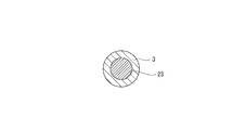
- connection cord 23 is positioned concentrically inside the apparatus main body 3 (see FIG. 32). Also in this case, good handling of the sound pickup device 1 can be ensured, and the durability of the connection cord 23 can be improved.
- each part of the apparatus main body 3 is formed of a conductor such as a metal
- the apparatus main body 3 can be used as a conductive part.
- the diameter of the connection cord 23 can be reduced by using the apparatus main body 3 as a ground line and using the connection cord 23 as a signal line.
- connection cord 23 can also be positioned through the upper side of the pinna 101 (see FIG. 33). By locating the connection cord 23 through the upper side of the pinna 101, the connection cord 23 is located on the back side of the pinna 101, so that interference between the connection cord 23 and the sound pickup device 1 can be suppressed.
- the sound pickup unit 2 can be made wireless (see FIG. 34).
- a module 25 for wireless communication that is attached or pressed to the back surface of the pinna 101 is attached to the outer engagement portion 9, and the module 25 and the sound pickup unit 2 are connected by a signal line 26.
- a battery 27 is built in the module 25.
- the sound input to the sound pickup unit 2 by wireless communication is transmitted as a sound signal to the module 25 via the signal line 26, and is transmitted from the module 25 to another device such as a measuring device by radio.
- connection cord for connecting the measuring instrument or the like to the sound pickup unit 2 is not required, and the structure can be simplified.
- the sound pickup device 1 may be provided with a sound output unit such as a speaker in addition to the sound pickup unit 2.
- a noise canceling function may be provided that outputs a sound signal having a phase opposite to that of the surrounding sound signal (noise) input to the sound pickup unit 2 so that the noise is hardly heard.
- a mounting section 4 and a holding section 5 are attached to a sound output section such as an earphone with an open ear hole or an earphone of a type having an ear cuff, and both the sound pickup section 2 and the sound output section are provided.
- An apparatus may be configured. Further, by attaching a sound output unit, which is a balanced armature, to the mounting unit 4 in addition to the sound pickup unit 2, it is possible to configure a device having both the sound pickup unit 2 and the sound output unit.
- a sensor may be attached to the sound pickup device 1. It is desirable that the sensor be attached to, for example, the attaching section 4 or the holding section 5 inserted into the external auditory canal 113.
- the sensor for example, a sensor for distance measurement, a contact type sensor, or the like is used. Further, a camera may be provided instead of the sensor.
- the sound pickup unit 2 can be held at an appropriate position and collected. With respect to the position of the sound part 2, high reproducibility at the time of each measurement can be secured.
- the positions of the sound pickup units 2 and 2 with respect to the external auditory canals 113 and 113 in the left and right ears 100 and 100 can be matched.
- information at the time of measurement may be detected by a sensor.
- vital signs such as the heart rate, pulse rate, respiration, blood pressure, and body temperature of the subject at the time of measurement, and weather information such as temperature and humidity may be detected.
- weather information such as temperature and humidity may be detected.
- the tilt, the tilt direction, and the like of the subject's head 200 may be detected using an acceleration sensor or the like.
- the sound collection device 1 may be provided with, for example, an actuator using a micromachine technology.
- the actuator for example, it is possible to insert the attachment unit 4 or the holding unit 5 into the external auditory canal 113, control the position of the sound collection unit 2 in the external auditory canal 113, or the like.
- the actuator by operating the actuator based on the information detected by the sensor, it is possible to position the sound collection unit 2 at an appropriate position in the external auditory canal 113.
- a MEMS microphone Micro Electro Mechanical Systems
- the sound pickup unit 2 may be used as the sound pickup unit 2 (see FIG. 35).
- a MEMS microphone is used as the sound pickup unit 2 since the MEMS microphone is formed in a substantially rectangular parallelepiped shape and the sound input hole 2 a is formed on one surface in the thickness direction, the sound pickup unit 2 is inserted into the external auditory canal 113. It is desirable to incline the voice input hole 2a with respect to the direction so as to face the outer ear hole 113a side.
- the MEMS microphone and the like are large, it is difficult to insert the MEMS microphone into the external auditory canal 113 when the thickness direction matches the insertion direction with respect to the external auditory canal 113.
- a propagation path of the sound from the entrance of the ear canal 113 to the eardrum 116 and a propagation path of the sound reflected by the eardrum 116 to the sound input hole 2a are secured.
- the sound input hole 2a is inclined so as to face the outer ear hole 113a, so that a sound propagation path to the sound input hole 2a is sufficiently ensured.
- the sound collecting unit 2 when a MEMS microphone or the like is used as the sound collecting unit 2, the sound collecting unit 2 is inclined so that the sound input hole 2 a faces the outer ear hole 113 a with respect to the insertion direction with respect to the ear canal 113. 2 can be secured to the external auditory canal 113, and a good input state of the sound to the sound collection unit 2 can be secured.
- the present technology can be configured as follows.
- the mounting portion is provided with an inner engaging portion which is continuous with the holding portion and at least a part of which is engaged with the pinna,
- the mounting portion is provided with an inner engaging portion which is continuous with the holding portion and at least a part of which is engaged with the pinna,
- the inner engagement portion is elastically deformable in a direction in which the inner engagement portion comes into contact with the holding portion,
- the sound collection device according to any one of (1) to (16), wherein the inner engagement portion is located in the concha of the ear.
- the mounting portion is provided with an inner engaging portion which is continuous with the holding portion and at least a part of which is engaged with the pinna,
- the sound collection device according to any one of (1) to (17), wherein an outer diameter of the inner engagement portion is larger than a diameter of an entrance of an ear canal.
- the outer engagement portion is provided with a pair of action portions, The outer engagement portion is configured to be elastically deformable in a direction in which the pair of action portions are separated from each other,
- the sound pickup device to which the technology disclosed in this specification is applied is used by being worn on the user's ear, but is significantly different from a conventional binaural microphone in that it is “open-ear type”. Therefore, the sound pickup device to which the technology disclosed in the present specification is applied realizes the same listening characteristics of the surrounding sound as in the non-wearing state even in the wearing state, while diffracting or reflecting on the inner wall of the ear canal or reflecting from the eardrum. It is possible to obtain a high-precision head-related transfer function that expresses a change in sound in consideration of the precise binaural recording that also takes into account the effect of sound, and the shape of the external auditory meatus and the effect of the sound reflected from the eardrum.
- Reference Signs List 100 ear, 101: pinna, 110: antitragus, 111: tragus, 113: external auditory canal, 114: concha of ear, 116: eardrum, 1: sound collecting device, 2: sound collecting unit, 2a: voice Input hole, 4 mounting portion, 5 holding portion, 6 mounting portion, 7 inner engaging portion, 9 outer engaging portion, 10 first operating portion, 12 second operating portion, 4A ... Mounting part, 4B mounting part, 5A holding part, 5B holding part, 5C holding part, 5D holding part, 5E holding part, 5F holding part, 5G holding part, 7A inside engagement part
Landscapes
- Engineering & Computer Science (AREA)
- Physics & Mathematics (AREA)
- Acoustics & Sound (AREA)
- Signal Processing (AREA)
- Manufacturing & Machinery (AREA)
- Health & Medical Sciences (AREA)
- Otolaryngology (AREA)
- Headphones And Earphones (AREA)
- Stereophonic Arrangements (AREA)
Abstract
L'invention concerne un dispositif de capture de son dans lequel l'entrée de son dans une partie de capture de son est réalisée de manière satisfaisante. Ce dispositif de capture de son est pourvu : d'une partie de montage sur laquelle est montée la partie de capture de son, et qui est insérée dans un conduit auditif externe ; une partie de retenue qui est insérée dans le canal auditif externe et retient la partie de montage dans une position prédéterminée dans le canal auditif externe ; et une partie de fixation qui est disposée sur le côté opposé à la partie de montage, la partie de retenue étant interposée entre celles-ci, et qui est au moins partiellement en prise avec une oreillette. La partie de montage et la partie de retenue présentent des propriétés de transmission acoustique et ne bloquent pas le canal auditif externe. Ainsi, la partie de montage, sur laquelle la partie de capture de son est montée et qui est insérée dans le canal auditif externe, et la partie de retenue, qui retient la partie de montage dans la position prédéterminée dans le canal auditif externe, sont positionnées dans l'oreille de façon à ne pas bloquer le canal auditif externe, ce qui permet de fournir un dispositif de capture de son dans lequel l'entrée de son dans une partie de capture de son est réalisée de manière satisfaisante.
Priority Applications (2)
| Application Number | Priority Date | Filing Date | Title |
|---|---|---|---|
| US17/250,396 US11477556B2 (en) | 2018-07-24 | 2019-05-09 | Sound collecting device |
| JP2020532172A JP7322883B2 (ja) | 2018-07-24 | 2019-05-09 | 収音装置 |
Applications Claiming Priority (2)
| Application Number | Priority Date | Filing Date | Title |
|---|---|---|---|
| JP2018138661 | 2018-07-24 | ||
| JP2018-138661 | 2018-07-24 |
Publications (1)
| Publication Number | Publication Date |
|---|---|
| WO2020021815A1 true WO2020021815A1 (fr) | 2020-01-30 |
Family
ID=69182197
Family Applications (1)
| Application Number | Title | Priority Date | Filing Date |
|---|---|---|---|
| PCT/JP2019/018584 Ceased WO2020021815A1 (fr) | 2018-07-24 | 2019-05-09 | Dispositif de capture de son |
Country Status (3)
| Country | Link |
|---|---|
| US (1) | US11477556B2 (fr) |
| JP (1) | JP7322883B2 (fr) |
| WO (1) | WO2020021815A1 (fr) |
Cited By (4)
| Publication number | Priority date | Publication date | Assignee | Title |
|---|---|---|---|---|
| JP2021093573A (ja) * | 2019-12-06 | 2021-06-17 | 株式会社今仙電機製作所 | イヤホン型マイクロフォン |
| WO2022264528A1 (fr) * | 2021-06-14 | 2022-12-22 | ソニーグループ株式会社 | Dispositif de collecte de son |
| WO2023095757A1 (fr) * | 2021-11-26 | 2023-06-01 | クレプシードラ株式会社 | Appareil acoustique |
| EP4280621A4 (fr) * | 2021-02-27 | 2024-07-17 | Huawei Technologies Co., Ltd. | Écouteur, ensemble écouteur et procédé associé |
Citations (2)
| Publication number | Priority date | Publication date | Assignee | Title |
|---|---|---|---|---|
| US20110098787A1 (en) * | 2009-10-28 | 2011-04-28 | Spearman Michael R | Cochlear implant |
| WO2018123252A1 (fr) * | 2016-12-29 | 2018-07-05 | ソニー株式会社 | Dispositif de prise de son |
Family Cites Families (4)
| Publication number | Priority date | Publication date | Assignee | Title |
|---|---|---|---|---|
| JP2004128854A (ja) | 2002-10-02 | 2004-04-22 | Matsushita Electric Ind Co Ltd | 音響再生装置 |
| GB0419346D0 (en) | 2004-09-01 | 2004-09-29 | Smyth Stephen M F | Method and apparatus for improved headphone virtualisation |
| EP3175631B1 (fr) * | 2014-07-28 | 2018-06-20 | Advanced Bionics AG | Module processeur de son |
| US10678502B2 (en) * | 2016-10-20 | 2020-06-09 | Qualcomm Incorporated | Systems and methods for in-ear control of remote devices |
-
2019
- 2019-05-09 WO PCT/JP2019/018584 patent/WO2020021815A1/fr not_active Ceased
- 2019-05-09 JP JP2020532172A patent/JP7322883B2/ja active Active
- 2019-05-09 US US17/250,396 patent/US11477556B2/en active Active
Patent Citations (2)
| Publication number | Priority date | Publication date | Assignee | Title |
|---|---|---|---|---|
| US20110098787A1 (en) * | 2009-10-28 | 2011-04-28 | Spearman Michael R | Cochlear implant |
| WO2018123252A1 (fr) * | 2016-12-29 | 2018-07-05 | ソニー株式会社 | Dispositif de prise de son |
Cited By (7)
| Publication number | Priority date | Publication date | Assignee | Title |
|---|---|---|---|---|
| JP2021093573A (ja) * | 2019-12-06 | 2021-06-17 | 株式会社今仙電機製作所 | イヤホン型マイクロフォン |
| JP7403296B2 (ja) | 2019-12-06 | 2023-12-22 | 株式会社今仙電機製作所 | イヤホン型マイクロフォン |
| EP4280621A4 (fr) * | 2021-02-27 | 2024-07-17 | Huawei Technologies Co., Ltd. | Écouteur, ensemble écouteur et procédé associé |
| US12501200B2 (en) | 2021-02-27 | 2025-12-16 | Huawei Technologies Co., Ltd. | Headset, headset assembly, and related method |
| WO2022264528A1 (fr) * | 2021-06-14 | 2022-12-22 | ソニーグループ株式会社 | Dispositif de collecte de son |
| US20240244373A1 (en) * | 2021-06-14 | 2024-07-18 | Sony Group Corporation | Sound pickup device |
| WO2023095757A1 (fr) * | 2021-11-26 | 2023-06-01 | クレプシードラ株式会社 | Appareil acoustique |
Also Published As
| Publication number | Publication date |
|---|---|
| JPWO2020021815A1 (ja) | 2021-08-02 |
| US20210258670A1 (en) | 2021-08-19 |
| US11477556B2 (en) | 2022-10-18 |
| JP7322883B2 (ja) | 2023-08-08 |
Similar Documents
| Publication | Publication Date | Title |
|---|---|---|
| JP7282043B2 (ja) | 耳介用装置を備える眼鏡 | |
| WO2020021815A1 (fr) | Dispositif de capture de son | |
| CN103957489B (zh) | 耳机 | |
| CN110291797B (zh) | 拾音装置和拾音方法 | |
| EP3565273B1 (fr) | Dispositif de prise de son | |
| CN107113487A (zh) | 声音输出装置和声音引导装置 | |
| CN110012373B (zh) | 耳内设备 | |
| JP7681890B2 (ja) | 音響装置 | |
| JP7626794B2 (ja) | 音響出力装置 | |
| JP7672740B2 (ja) | 音響装置 | |
| US11388501B2 (en) | Earpiece with actuator | |
| KR102100845B1 (ko) | 마이크를 외장한 난청 보상 장치 | |
| JP4523065B1 (ja) | イヤホン | |
| US20240244373A1 (en) | Sound pickup device | |
| JP7347927B2 (ja) | 電気音響変換器及び音響機器 | |
| CN100536606C (zh) | 电声换能装置 | |
| WO2022054714A1 (fr) | Dispositif d'écoute | |
| JP7239152B2 (ja) | 挿入式パッシブ・ノイズキャンセル・イヤホン | |
| JP3187151U (ja) | 対話聴力補助器 | |
| JPH099383A (ja) | イヤホン等のイヤピース | |
| CN207802291U (zh) | 耳机 | |
| JP3205166B2 (ja) | イヤーマイクロフォン | |
| JP2009239736A (ja) | イヤースピーカ装置およびイヤーパッド |
Legal Events
| Date | Code | Title | Description |
|---|---|---|---|
| 121 | Ep: the epo has been informed by wipo that ep was designated in this application |
Ref document number: 19841747 Country of ref document: EP Kind code of ref document: A1 |
|
| ENP | Entry into the national phase |
Ref document number: 2020532172 Country of ref document: JP Kind code of ref document: A |
|
| NENP | Non-entry into the national phase |
Ref country code: DE |
|
| 122 | Ep: pct application non-entry in european phase |
Ref document number: 19841747 Country of ref document: EP Kind code of ref document: A1 |