WO2020021864A1 - Dispositif de traitement d'image médicale - Google Patents
Dispositif de traitement d'image médicale Download PDFInfo
- Publication number
- WO2020021864A1 WO2020021864A1 PCT/JP2019/022047 JP2019022047W WO2020021864A1 WO 2020021864 A1 WO2020021864 A1 WO 2020021864A1 JP 2019022047 W JP2019022047 W JP 2019022047W WO 2020021864 A1 WO2020021864 A1 WO 2020021864A1
- Authority
- WO
- WIPO (PCT)
- Prior art keywords
- region
- medical image
- interest
- image processing
- state
- Prior art date
- Legal status (The legal status is an assumption and is not a legal conclusion. Google has not performed a legal analysis and makes no representation as to the accuracy of the status listed.)
- Ceased
Links
Images







Classifications
-
- G—PHYSICS
- G09—EDUCATION; CRYPTOGRAPHY; DISPLAY; ADVERTISING; SEALS
- G09G—ARRANGEMENTS OR CIRCUITS FOR CONTROL OF INDICATING DEVICES USING STATIC MEANS TO PRESENT VARIABLE INFORMATION
- G09G5/00—Control arrangements or circuits for visual indicators common to cathode-ray tube indicators and other visual indicators
- G09G5/14—Display of multiple viewports
-
- A—HUMAN NECESSITIES
- A61—MEDICAL OR VETERINARY SCIENCE; HYGIENE
- A61B—DIAGNOSIS; SURGERY; IDENTIFICATION
- A61B1/00—Instruments for performing medical examinations of the interior of cavities or tubes of the body by visual or photographical inspection, e.g. endoscopes; Illuminating arrangements therefor
- A61B1/00002—Operational features of endoscopes
- A61B1/00004—Operational features of endoscopes characterised by electronic signal processing
- A61B1/00009—Operational features of endoscopes characterised by electronic signal processing of image signals during a use of endoscope
- A61B1/000094—Operational features of endoscopes characterised by electronic signal processing of image signals during a use of endoscope extracting biological structures
-
- A—HUMAN NECESSITIES
- A61—MEDICAL OR VETERINARY SCIENCE; HYGIENE
- A61B—DIAGNOSIS; SURGERY; IDENTIFICATION
- A61B1/00—Instruments for performing medical examinations of the interior of cavities or tubes of the body by visual or photographical inspection, e.g. endoscopes; Illuminating arrangements therefor
- A61B1/00002—Operational features of endoscopes
- A61B1/00043—Operational features of endoscopes provided with output arrangements
- A61B1/00045—Display arrangement
- A61B1/0005—Display arrangement combining images e.g. side-by-side, superimposed or tiled
-
- A—HUMAN NECESSITIES
- A61—MEDICAL OR VETERINARY SCIENCE; HYGIENE
- A61B—DIAGNOSIS; SURGERY; IDENTIFICATION
- A61B1/00—Instruments for performing medical examinations of the interior of cavities or tubes of the body by visual or photographical inspection, e.g. endoscopes; Illuminating arrangements therefor
- A61B1/00002—Operational features of endoscopes
- A61B1/00043—Operational features of endoscopes provided with output arrangements
- A61B1/00055—Operational features of endoscopes provided with output arrangements for alerting the user
-
- A—HUMAN NECESSITIES
- A61—MEDICAL OR VETERINARY SCIENCE; HYGIENE
- A61B—DIAGNOSIS; SURGERY; IDENTIFICATION
- A61B1/00—Instruments for performing medical examinations of the interior of cavities or tubes of the body by visual or photographical inspection, e.g. endoscopes; Illuminating arrangements therefor
- A61B1/04—Instruments for performing medical examinations of the interior of cavities or tubes of the body by visual or photographical inspection, e.g. endoscopes; Illuminating arrangements therefor combined with photographic or television appliances
- A61B1/045—Control thereof
-
- G—PHYSICS
- G06—COMPUTING OR CALCULATING; COUNTING
- G06T—IMAGE DATA PROCESSING OR GENERATION, IN GENERAL
- G06T7/00—Image analysis
- G06T7/0002—Inspection of images, e.g. flaw detection
- G06T7/0012—Biomedical image inspection
-
- G—PHYSICS
- G06—COMPUTING OR CALCULATING; COUNTING
- G06V—IMAGE OR VIDEO RECOGNITION OR UNDERSTANDING
- G06V10/00—Arrangements for image or video recognition or understanding
- G06V10/20—Image preprocessing
- G06V10/25—Determination of region of interest [ROI] or a volume of interest [VOI]
-
- G—PHYSICS
- G09—EDUCATION; CRYPTOGRAPHY; DISPLAY; ADVERTISING; SEALS
- G09G—ARRANGEMENTS OR CIRCUITS FOR CONTROL OF INDICATING DEVICES USING STATIC MEANS TO PRESENT VARIABLE INFORMATION
- G09G5/00—Control arrangements or circuits for visual indicators common to cathode-ray tube indicators and other visual indicators
- G09G5/36—Control arrangements or circuits for visual indicators common to cathode-ray tube indicators and other visual indicators characterised by the display of a graphic pattern, e.g. using an all-points-addressable [APA] memory
- G09G5/37—Details of the operation on graphic patterns
-
- G—PHYSICS
- G16—INFORMATION AND COMMUNICATION TECHNOLOGY [ICT] SPECIALLY ADAPTED FOR SPECIFIC APPLICATION FIELDS
- G16H—HEALTHCARE INFORMATICS, i.e. INFORMATION AND COMMUNICATION TECHNOLOGY [ICT] SPECIALLY ADAPTED FOR THE HANDLING OR PROCESSING OF MEDICAL OR HEALTHCARE DATA
- G16H30/00—ICT specially adapted for the handling or processing of medical images
- G16H30/20—ICT specially adapted for the handling or processing of medical images for handling medical images, e.g. DICOM, HL7 or PACS
-
- G—PHYSICS
- G16—INFORMATION AND COMMUNICATION TECHNOLOGY [ICT] SPECIALLY ADAPTED FOR SPECIFIC APPLICATION FIELDS
- G16H—HEALTHCARE INFORMATICS, i.e. INFORMATION AND COMMUNICATION TECHNOLOGY [ICT] SPECIALLY ADAPTED FOR THE HANDLING OR PROCESSING OF MEDICAL OR HEALTHCARE DATA
- G16H30/00—ICT specially adapted for the handling or processing of medical images
- G16H30/40—ICT specially adapted for the handling or processing of medical images for processing medical images, e.g. editing
-
- G—PHYSICS
- G06—COMPUTING OR CALCULATING; COUNTING
- G06T—IMAGE DATA PROCESSING OR GENERATION, IN GENERAL
- G06T2207/00—Indexing scheme for image analysis or image enhancement
- G06T2207/30—Subject of image; Context of image processing
- G06T2207/30004—Biomedical image processing
-
- G—PHYSICS
- G06—COMPUTING OR CALCULATING; COUNTING
- G06V—IMAGE OR VIDEO RECOGNITION OR UNDERSTANDING
- G06V2201/00—Indexing scheme relating to image or video recognition or understanding
- G06V2201/03—Recognition of patterns in medical or anatomical images
-
- G—PHYSICS
- G09—EDUCATION; CRYPTOGRAPHY; DISPLAY; ADVERTISING; SEALS
- G09G—ARRANGEMENTS OR CIRCUITS FOR CONTROL OF INDICATING DEVICES USING STATIC MEANS TO PRESENT VARIABLE INFORMATION
- G09G2354/00—Aspects of interface with display user
-
- G—PHYSICS
- G09—EDUCATION; CRYPTOGRAPHY; DISPLAY; ADVERTISING; SEALS
- G09G—ARRANGEMENTS OR CIRCUITS FOR CONTROL OF INDICATING DEVICES USING STATIC MEANS TO PRESENT VARIABLE INFORMATION
- G09G2380/00—Specific applications
- G09G2380/08—Biomedical applications
-
- G—PHYSICS
- G09—EDUCATION; CRYPTOGRAPHY; DISPLAY; ADVERTISING; SEALS
- G09G—ARRANGEMENTS OR CIRCUITS FOR CONTROL OF INDICATING DEVICES USING STATIC MEANS TO PRESENT VARIABLE INFORMATION
- G09G5/00—Control arrangements or circuits for visual indicators common to cathode-ray tube indicators and other visual indicators
- G09G5/02—Control arrangements or circuits for visual indicators common to cathode-ray tube indicators and other visual indicators characterised by the way in which colour is displayed
Definitions
- the present invention relates to a medical image processing device that uses a result of analyzing a medical image.
- medical diagnosis such as endoscopic images, X-ray images, CT (Computed Tomography) images, and MR (Magnetic Resonanse) images are used to perform image diagnosis such as diagnosis of a patient's medical condition and follow-up observation. ing. Based on such image diagnosis, doctors and the like make decisions on treatment policies and the like.
- Patent Literature 1 describes an endoscope (medical image processing device) that displays an alert when a region of interest is detected. Further, Patent Literature 1 below describes a configuration in which an alert is continuously displayed even when a region of interest goes out of a screen.
- the apparatus described in Patent Document 1 has a problem that the inspection load is large.
- the detection state of the region of interest (whether the region of interest is detected or the region of interest is not detected) is changed. Since the elapsed time cannot be ascertained, it is not known how far back in order to return the region of interest to the inside of the screen to be in the detection state when the region of interest has gone out of the screen and becomes undetected. Therefore, a load for returning the region of interest to the screen and returning (shifting) from the undetected state to the detected state becomes large.
- the present invention has been made in view of the above background, and has as its object to provide a medical image processing apparatus capable of reducing the inspection load.
- the medical image processing apparatus of the present invention is A medical image acquisition unit that acquires a medical image obtained by imaging the observation target, A region of interest detection unit that detects a region of interest from a medical image, A display control unit for displaying notification information and a medical image notifying that the region of interest has been detected on the display unit, The display control unit changes the display mode of the notification information using the detection state of the region of interest and the elapsed time after the detection state changes.
- the display control unit refers to an elapsed time after the detection state of the region of interest is shifted from a detection state in which the region of interest is detected to an undetected state in which the region of interest is not detected, and displays the display mode of the notification information. May be changed.
- the display control unit displays notification information in a first display mode when the detection state of the region of interest shifts from an undetected state where the region of interest is not detected to a detection state where the region of interest is detected.
- the notification information may be displayed in the second display mode when the detection state of the area changes from the detection state to the non-detection state.
- the region of interest may be displayed over the medical image.
- the display control unit may display the elapsed time from when the detection state of the region of interest has shifted from the detection state to the non-detection state as notification information.
- the notification information may be displayed in the form of a circular or linear time bar whose length changes according to the elapsed time.
- the notification information may be information in which the elapsed time is displayed in the form of characters or numbers.
- the notification information may be displayed in a form in which the hue or the shading is changed according to the elapsed time.
- a first area for displaying a medical image and a second area for displaying notification information may be provided.
- the second region may be provided on the outer periphery of the first region.
- the display control unit may indicate the detection position of the region of interest in the medical image by a display mode of the notification information.
- the display control unit may indicate the latest detected position among the detected positions of the region of interest by the display mode of the notification information.
- the display control unit may indicate the detection position by the display position of the notification information.
- the inspection load can be reduced.
- FIG. 2 is a block diagram illustrating a medical image processing device, an endoscope device, and the like. It is a block diagram showing an endoscope apparatus. It is a block diagram showing the function of a medical image analysis processing part. It is an explanatory view showing a display mode of information information. It is an explanatory view showing a display mode of information information. It is an explanatory view showing a display mode of information information. It is an explanatory view showing a display mode of information information. It is an explanatory view showing a display mode of information information. It is an explanatory view showing a display mode of information information. It is an explanatory view showing a display mode of information information. It is an explanatory view showing a display mode of information information. It is an explanatory view showing a display mode of information information. It is an explanatory view showing a display mode of information information. It is an explanatory view showing a display mode of information information. It is an explanatory view showing a display mode of information information. It is an ex
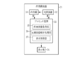
- the medical image processing apparatus 10 includes a medical image acquisition unit 11, a medical image analysis processing unit 12, a display unit 13, a display control unit 15, an input reception unit 16, an overall control unit 17, and a storage unit. 18 is provided.
- the medical image acquisition unit 11 acquires a medical image including a subject image directly from the endoscope device 21 or the like, or via a management system such as a PACS (Picture Archiving and Communication System) 22 or another information system.
- the medical image is a still image or a moving image (a so-called inspection moving image).
- the medical image acquiring unit 11 can acquire a frame image forming the moving image as a still image after the examination.
- displaying the medical image includes displaying the still image of one representative frame constituting the moving image and reproducing the moving image one or more times.
- the medical image acquired by the medical image acquiring unit 11 includes, in addition to an image photographed by a doctor using a medical device such as the endoscope device 21, a medical device such as the endoscope device 21 in response to a doctor's photographing instruction. Includes images taken automatically regardless of In the present embodiment, since the medical image processing apparatus 10 and the endoscope apparatus 21 perform image processing using medical images, both the medical image processing apparatus 10 and the endoscope apparatus 21 perform medical image processing according to the present invention. It corresponds to a processing device.
- the medical image obtaining unit 11 can selectively obtain one or a plurality of medical images among these medical images. Further, the medical image acquisition unit 11 can acquire a plurality of medical images acquired in a plurality of different examinations. For example, one or both of a medical image obtained by a test performed in the past and a medical image obtained by the latest test can be obtained. That is, the medical image acquisition unit 11 can arbitrarily acquire a medical image.
- a plurality of medical images including a subject image are acquired. More specifically, when a medical image taken in one specific examination is acquired, and there are a plurality of medical images taken in one particular examination, a plurality of medical images in a series of medical images are acquired. Get an image.
- the medical image processing device 10 is connected to the endoscope device 21 and acquires a medical image from the endoscope device 21. That is, in the present embodiment, the medical image is an endoscope image.
- the display unit 13 is a display that displays the medical image acquired by the medical image acquisition unit 11 and the analysis result of the medical image analysis processing unit 12.
- a monitor or display included in a device or the like connected to the medical image processing apparatus 10 can be shared and used as the display unit 13 of the medical image processing apparatus 10.
- the display control unit 15 controls a display mode of the medical image and the analysis result on the display unit 13.
- the input receiving unit 16 receives inputs from a mouse, a keyboard, and other operation devices connected to the medical image processing apparatus 10. The operation of each unit of the medical image processing apparatus 10 can be controlled using these operation devices.
- the general control unit 17 controls the operation of each unit of the medical image processing apparatus 10 in a comprehensive manner.
- the overall control unit 17 controls each unit of the medical image processing apparatus 10 according to the operation input.
- the storage unit 18 stores a still image of a medical image in a storage device (not shown) such as a memory included in the medical image processing apparatus 10 or a medical device such as the endoscope device 21 or a storage device (not shown) included in the PACS 22. Save etc.
- a storage device such as a memory included in the medical image processing apparatus 10 or a medical device such as the endoscope device 21 or a storage device (not shown) included in the PACS 22. Save etc.
- the endoscope apparatus 21 to which the medical image processing apparatus 10 is connected in the present embodiment irradiates at least one of light in a white wavelength band or light in a specific wavelength band to photograph a subject.
- Endoscope 31 that obtains an image by performing the operation, a light source device 32 that irradiates the subject with illumination light through the endoscope 31, a processor device 33, and an endoscope image captured using the endoscope 31 And the like for displaying the information.
- the light in the specific wavelength band used by the endoscope 31 as the illumination light is, for example, light in a shorter wavelength band than the green wavelength band, particularly light in the blue or violet band in the visible region.
- the processor device 33 includes a medical image acquisition unit 35, a medical image analysis processing unit 36, and a display control unit 37.
- the medical image acquisition unit 35 acquires a medical image output from the endoscope 31.
- the medical image analysis processing unit 36 performs an analysis process on the medical image acquired by the medical image acquisition unit 35.
- the processing content of the medical image analysis processing unit 36 is the same as the processing content of the medical image analysis processing unit 12 of the medical image processing device 10.
- the display control unit 37 displays the medical image obtained by the medical image analysis processing unit 36 on the display unit 34.
- the processor device 33 is connected to the medical image processing device 10.
- the display unit 34 is equivalent to the display unit 13
- the medical image acquisition unit 35 is similar to the medical image acquisition unit 11
- the medical image analysis processing unit 36 is similar to the medical image analysis processing unit 12, and the display control is performed.
- the unit 37 is the same as the display control unit 15.
- the medical image analysis processing unit 36 performs an analysis process using the medical image acquired by the medical image acquisition unit 11.
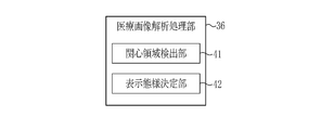
- the medical image analysis processing unit 36 includes a region of interest detection unit 41 and a display mode determination unit 42.
- the region-of-interest detection unit 41 performs a region-of-interest detection process for detecting the region of interest 47 (see FIGS. 4 to 6, 16, 17, and 20) from the medical image.
- NN Neurological Network
- CNN Convolutional Neural Network
- Adaboost random forest, or the like
- the region-of-interest detection processing the region-of-interest 47 may be detected based on feature information obtained by color information of a medical image, a gradient of pixel values, and the like.
- the gradient of the pixel value and the like are, for example, the shape of the subject (global undulation or local depression or protuberance of the mucous membrane), color (color such as inflammation, bleeding, redness, or whitening caused by atrophy).
- the change appears depending on the characteristics of the tissue (the thickness, the depth, the density of the blood vessel, or a combination thereof) or the characteristics of the structure (such as the pit pattern).
- the region of interest 47 detected by the region-of-interest detection unit 41 includes, for example, a lesion represented by cancer, a benign tumor, and an inflammation (in addition to so-called inflammation, a part having a change such as bleeding or atrophy). ), An area including a marking portion marked by cauterization by heating or coloring with a coloring agent, a fluorescent agent, or the like, or a biopsy performing portion that has performed a biopsy (so-called biopsy).
- the region of interest detection unit 41 detects, as the region of interest 47, a region including at least one of a lesion, a benign tumor, an inflammation, a marking, and a biopsy performing unit.
- the display mode determination unit 42 determines the display mode of the notification information for notifying that the region of interest 47 has been detected, and the display mode of the medical image 43 (see FIGS. 4 to 17).
- the display control unit 37 displays the notification information and the medical image 43 on the display unit 34 according to the determined display mode.
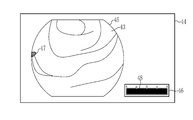
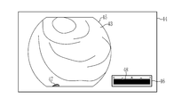
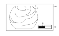
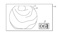
- FIGS. 4 to 9 show a display screen 44 in which a series of medical images 43 sequentially acquired in accordance with an endoscopic examination are displayed in a screen (in a first area 45) in the order of acquisition. 4, 5, and 6 show a detection state in which the region of interest 47 is detected, and FIGS. 7, 8, and 9 show a non-detection state in which the region of interest 47 is not detected.
- the area of interest 47 is displayed so as to overlap the medical image 43 (see FIGS. 4, 5, and 6).
- the undetected state only the medical image 43 is displayed in the first area 45 (see FIGS. 7, 8, and 9).
- the region of interest 47 is hatched and displayed over the medical image 43 (see FIGS. 4, 5, and 6), but the present invention is not limited to this.
- the region of interest 47 may be colored and displayed over the medical image 43.
- only the outline of the region of interest 47 may be colored and emphasized so as to be superimposed on the medical image 43 and displayed.
- the display mode when the region of interest 47 is displayed so as to be superimposed on the medical image 43 can be appropriately changed.
- the present invention is not limited to a mode in which the region of interest 47 is displayed so as to be superimposed on the medical image 43.
- the region of interest 47 may be emphasized by surrounding it with a frame.
- the first area 45 displays or displays the region of interest 47 even in the detection state.
- a configuration may be adopted in which only the medical image 43 is displayed without emphasis.
- a configuration in which the state of displaying or emphasizing the region of interest 47 and the state of displaying only the medical image 43 without displaying the region of interest 47 are switched by a selection operation of a user (such as a doctor performing an endoscopy) is adopted. Is also good.
- notification information indicating the presence of the region of interest 47 in the medical image 43 is displayed in the second region 46 (see FIGS. 4, 5, and 6).
- the notification information is displayed in the form of a bar 48 (time bar).
- This bar 48 is displayed in the longest state when the state changes from the undetected state to the detected state, and is maintained in the longest state until the state changes from the detected state to the undetected state. .
- the bar 48 shifts from the detected state to the undetected state the length of the bar 48 decreases as time elapses (see FIGS. 7, 8, and 9).
- a bar 48 whose length decreases with time when a transition is made from the detected state to the undetected state is displayed.
- the bar 48 has a length of 0 and disappears after a certain period of time has passed since the transition to the undetected state (the bar 48 is not displayed, see FIG. 9).
- the length of the bar 48 returns to the longest (see FIGS. 4, 5 and 6).
- the user can change the detection state. It is possible to know whether or not and the elapsed time since the undetected state.
- the display mode display mode of the notification information
- the present invention is not limited to the above embodiment, and the configuration of the details can be changed as appropriate.
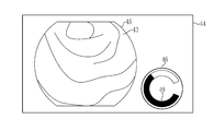
- the elapsed time is indicated by a linear bar, but the elapsed time may be indicated by a circular bar 49 as shown in FIG.
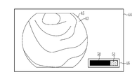
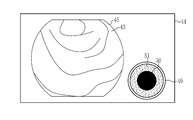
- the elapsed time may be indicated by a change in color (display color).
- regions 50 and 51 colored with different colors are provided in the second region 46, and the entire second region 46 is set as the region 50 during the detection state. Accordingly, the elapsed time is shown by decreasing the area 50 (the length of the area 50 is shortened in FIG. 11 and the diameter of the area 50 is decreased in FIG.
- the elapsed time may be indicated by a change in lightness and / or lightness of a color (display color).
- the elapsed time may be indicated by a numeral.
- FIG. 13 shows the elapsed time by performing a countdown in the second area 46 (decreasing the numerical value of the second area 46 by 1 every second) when the state shifts from the detection state to the non-detection state.
- the elapsed time may be indicated by characters.
- the elapsed time may be indicated by combining a plurality of the above-described methods, such as indicating the elapsed time by both a bar and a numerical value.
- the example has been described in which the elapsed time is indicated by a decrease in a bar and / or a numerical value.
- the elapsed time may be indicated by an increase in a bar and / or a numerical value.
- the same members as those in the above-described embodiment are denoted by the same reference numerals, and the description is omitted.
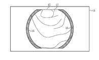
- the second region 46 may be provided on the outer periphery of the first region 45 as shown in FIGS.
- the outer peripheral portion of the first region 45 may be a region inside the first region 45.
- the inside and the outer edge of the first region 45 (the region indicated by hatching in FIG. 14) is the second region 46.
- the outer peripheral portion of the first region 45 may be a region outside the first region 45.
- a rectangular frame-shaped region (a region indicated by hatching in FIG. 15) provided outside the first region 45 so as to surround the first region 45 is defined as the second region 46.
- the outer peripheral portion of the first region 45 may be a region that straddles both the region inside the first region 45 and the region outside the first region 45.
- the region of interest 47 is detected based on the display content of the second region 46 and the elapsed time since the region of interest 47 is not detected is notified.
- the invention is not limited to this.
- the detection position of the region of interest 47 may be notified. 16 and 20, the second region 46 is formed by providing the second region 46 on the outer peripheral portion of the first region 45 and dividing the second region 46 into four by a line segment passing through the center of the first region 45. The detection position of the region of interest 47 is notified according to which of the four regions 52 to 55 the bar 56 is displayed.
- the detection state is changed from the non-detection state to the detection state, it is checked whether the region of interest 47 is detected in the upper right of the screen, the lower right of the screen, the upper left of the screen, or the lower left of the screen. Is detected in the area 52 at the upper right of the screen in the second area 46, and when the area of interest 47 is detected in the area at the lower right of the screen, the area 53 at the lower right of the screen in the second area 46, the area of interest When 47 is detected in the upper left area of the screen, the upper left area 54 of the second area 46 is displayed, and when the area of interest 47 is detected in the lower left area of the screen, the lower left area 55 of the second area 46 is displayed.
- FIGS. 16 and 20 show a state in which the region of interest 47 is detected in the region 52 at the upper right of the screen, and the bar 56 is displayed in this region 52.
- the display position of the bar 56 (the display area) is also moved in accordance with the change in the position of the region of interest 47, and when the state is shifted from the detection state to the undetected state, the display position of the bar 56 is displayed.
- the bar 56 is displayed at a position (region) corresponding to the latest detection position among the detection positions of the region of interest 47), and the length of the bar 56 decreases with time (for example, The bar 56 is reduced from both ends so that the bar 56 remains at the corner of the second area 46.
- the display mode of the second area 46 for notifying the detection position of the area of interest 47 is not limited to this.
- FIGS. 16 and 20 described above an example in which the display position of the bar 56 in the second area 46 is changed according to the position of the region of interest 47 has been described, but the display position of the second area 46 itself is described. And / or the shape may be changed according to the position of the region of interest 47.
- information regarding the region of interest 47 may be displayed in a region of the second region 46 that is different from the detection position of the region of interest 47.
- FIG. 16 and 20 an example in which the display position of the bar 56 in the second area 46 is changed according to the position of the region of interest 47 has been described, but the display position of the second area 46 itself is described. And / or the shape may be changed according to the position of the region of interest 47.
- information regarding the region of interest 47 may be displayed in a region of the second region 46 that is different from the detection position of the region of interest 47.
- the region 52 corresponding to the detection position of the region of interest 47 is blue, and the region 55 farthest from the detection position of the region of interest 47 (not adjacent to the region corresponding to the detection position of the region of interest 47).
- the region 55) is colored red, for example, and the regions 53 and 54 adjacent to the region corresponding to the detection position of the region of interest 47 are colored yellow, for example.
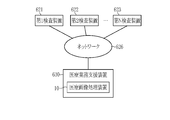
- the diagnosis support apparatus 610 used in combination with the endoscope apparatus 21 and other modalities and the PACS 22 can include the medical image processing apparatus 10 of the above embodiment and other modified examples.
- the medical service support apparatus 630 to be connected can include the medical image processing apparatus 10 of the above embodiment and other modified examples.
- various devices or systems including the medical image processing device 10, the endoscope device 21, and the medical image processing device 10 can be used with the following various modifications.
- a white band light or a normal light image obtained by irradiating a plurality of wavelength bands as white band light can be used.
- the specific wavelength band can be a band narrower than the white wavelength band.
- the specific wavelength band is, for example, a visible blue band or a green band.
- the specific wavelength band is a visible blue band or a green band
- the specific wavelength band includes a wavelength band of 390 nm to 450 nm or 530 nm to 550 nm, and light of the specific wavelength band is 390 nm or more. It preferably has a peak wavelength in a wavelength band of 450 nm or less or 530 nm or more and 550 nm or less.
- the specific wavelength band is, for example, a red band in the visible region.
- the specific wavelength band is a visible red band
- the specific wavelength band includes a wavelength band of 585 nm or more and 615 nm or 610 nm or more and 730 nm or less, and light of the specific wavelength band is 585 nm or more and 615 nm or less or 610 nm. It is preferable to have a peak wavelength in a wavelength band of 730 nm or less.
- the specific wavelength band includes, for example, a wavelength band having a different absorption coefficient between oxyhemoglobin and reduced hemoglobin, and light of a specific wavelength band has a peak wavelength at a wavelength band having a different absorption coefficient between oxyhemoglobin and reduced hemoglobin. Can be provided.
- the specific wavelength band includes a wavelength band having a different extinction coefficient between oxyhemoglobin and reduced hemoglobin, and light of a specific wavelength band has a peak wavelength in a wavelength band having a different extinction coefficient between oxyhemoglobin and reduced hemoglobin.
- the specific wavelength band includes a wavelength band of 400 ⁇ 10 nm, 440 ⁇ 10 nm, 470 ⁇ 10 nm, or 600 nm or more and 750 nm or less, and light of the specific wavelength band is 400 ⁇ 10 nm, 440 ⁇ 10 nm, It preferably has a peak wavelength in a wavelength band of 470 ⁇ 10 nm, or 600 nm to 750 nm.
- the in-vivo image can include information on fluorescence emitted from a fluorescent substance in the living body.
- fluorescence fluorescence obtained by irradiating the living body with excitation light having a peak wavelength of 390 nm to 470 nm can be used.
- the above-described specific wavelength band can use a wavelength band of infrared light.
- the specific wavelength band is a wavelength band of 790 nm to 820 nm or a wavelength band of 905 nm to 970 nm.
- light in a specific wavelength band preferably has a peak wavelength in a wavelength band of 790 nm to 820 nm or 905 nm to 970 nm.
- the medical image acquisition unit 11 acquires a special light image having a signal in a specific wavelength band based on a normal light image obtained by irradiating light in a plurality of wavelength bands as light in a white band or light in a white band.
- a special light image acquisition unit can be provided. In this case, a special light image can be used as a medical image.
- a signal in a specific wavelength band can be obtained by an operation based on RGB or CMY color information included in a normal light image.
- the image processing apparatus may further include a feature image generating unit that generates a feature image.
- a feature image can be used as a medical image.
- a capsule endoscope can be used as the endoscope 31.
- the light source device 32 and a part of the processor device 33 can be mounted on the capsule endoscope.
- the hardware structure of a processing unit (processing @ unit) that performs various types of processing, such as an image acquisition unit 35, a medical image analysis processing unit 36, a display control unit 37, a region of interest detection unit 41, and a display mode determination unit 42, is Various processors as shown in FIG.
- the various processors include a general-purpose processor (Central Processing Unit), a GPU (Graphical Processing Unit), an FPGA (Field Programmable Gate Array), which is a general-purpose processor that executes software (programs) and functions as various processing units.
- a programmable logic device Programmable Logic Device: PLD
- a dedicated electric circuit which is a processor having a circuit configuration specifically designed to execute various processes, and the like.
- One processing unit may be constituted by one of these various processors, or a combination of two or more processors of the same type or different types (for example, a plurality of FPGAs, a combination of a CPU and an FPGA, or a combination of a CPU and a CPU). GPU combination).
- a plurality of processing units may be configured by one processor.
- a plurality of processing units are configured by one processor, first, as represented by a computer such as a client or a server, one processor is configured by a combination of one or more CPUs and software, There is a form in which this processor functions as a plurality of processing units.
- SoC System-On-Chip
- SoC System-On-Chip
- the hardware structure of these various processors is more specifically an electric circuit (circuitry) in which circuit elements such as semiconductor elements are combined.
Landscapes
- Engineering & Computer Science (AREA)
- Health & Medical Sciences (AREA)
- Life Sciences & Earth Sciences (AREA)
- Physics & Mathematics (AREA)
- General Health & Medical Sciences (AREA)
- Medical Informatics (AREA)
- Radiology & Medical Imaging (AREA)
- Nuclear Medicine, Radiotherapy & Molecular Imaging (AREA)
- Surgery (AREA)
- Public Health (AREA)
- Theoretical Computer Science (AREA)
- General Physics & Mathematics (AREA)
- Animal Behavior & Ethology (AREA)
- Pathology (AREA)
- Biomedical Technology (AREA)
- Heart & Thoracic Surgery (AREA)
- Molecular Biology (AREA)
- Biophysics (AREA)
- Optics & Photonics (AREA)
- Veterinary Medicine (AREA)
- Computer Hardware Design (AREA)
- Epidemiology (AREA)
- Primary Health Care (AREA)
- Quality & Reliability (AREA)
- Computer Vision & Pattern Recognition (AREA)
- Multimedia (AREA)
- Signal Processing (AREA)
- Endoscopes (AREA)
- Measuring And Recording Apparatus For Diagnosis (AREA)
Abstract
L'invention concerne un dispositif de traitement d'image médicale qui peut réduire la charge d'essai. Une barre (48) est affichée dans une seconde région (46). Lors de la transition d'un état non détecté dans lequel une région d'intérêt n'est pas détectée à un état détecté dans lequel la région d'intérêt est détectée, l'affichage de la barre (48) est déclenché dans l'état de longueur maximale, et jusqu'à la transition de l'état détecté à l'état non détecté, l'affichage de la barre est maintenu dans l'état de longueur maximale. En outre, lors de la transition de l'état détecté à l'état non détecté, la longueur de la barre (48) diminue avec le passage du temps, et lorsqu'une période de temps prescrite s'est écoulée, la longueur devient nulle et la barre disparaît. En outre, dans le cas d'une transition vers l'état détecté avant que la barre (40) disparaisse, la longueur de la barre (48) revient à la longueur maximale.
Priority Applications (7)
| Application Number | Priority Date | Filing Date | Title |
|---|---|---|---|
| EP24154246.3A EP4339900A3 (fr) | 2018-07-27 | 2019-06-03 | Appareil de traitement d'image médicale, système d'endoscope et procédé de fonctionnement d'appareil de traitement d'image médicale |
| JP2020532194A JP7125987B2 (ja) | 2018-07-27 | 2019-06-03 | 医療画像処理装置 |
| CN201980050136.4A CN112512398B (zh) | 2018-07-27 | 2019-06-03 | 医疗图像处理装置 |
| EP19842298.2A EP3831272B1 (fr) | 2018-07-27 | 2019-06-03 | Dispositif de traitement d'image médicale |
| US17/129,864 US11605363B2 (en) | 2018-07-27 | 2020-12-21 | Medical image processing apparatus for reducing examination load |
| US18/151,473 US11881190B2 (en) | 2018-07-27 | 2023-01-09 | Medical image processing apparatus |
| US18/523,831 US12217726B2 (en) | 2018-07-27 | 2023-11-29 | Medical image processing apparatus |
Applications Claiming Priority (2)
| Application Number | Priority Date | Filing Date | Title |
|---|---|---|---|
| JP2018-140953 | 2018-07-27 | ||
| JP2018140953 | 2018-07-27 |
Related Child Applications (1)
| Application Number | Title | Priority Date | Filing Date |
|---|---|---|---|
| US17/129,864 Continuation US11605363B2 (en) | 2018-07-27 | 2020-12-21 | Medical image processing apparatus for reducing examination load |
Publications (1)
| Publication Number | Publication Date |
|---|---|
| WO2020021864A1 true WO2020021864A1 (fr) | 2020-01-30 |
Family
ID=69180889
Family Applications (1)
| Application Number | Title | Priority Date | Filing Date |
|---|---|---|---|
| PCT/JP2019/022047 Ceased WO2020021864A1 (fr) | 2018-07-27 | 2019-06-03 | Dispositif de traitement d'image médicale |
Country Status (5)
| Country | Link |
|---|---|
| US (3) | US11605363B2 (fr) |
| EP (2) | EP4339900A3 (fr) |
| JP (1) | JP7125987B2 (fr) |
| CN (1) | CN112512398B (fr) |
| WO (1) | WO2020021864A1 (fr) |
Cited By (2)
| Publication number | Priority date | Publication date | Assignee | Title |
|---|---|---|---|---|
| WO2021199294A1 (fr) * | 2020-03-31 | 2021-10-07 | 日本電気株式会社 | Dispositif de traitement d'informations, procédé d'affichage, et support non transitoire lisible par ordinateur sur lequel est stocké un programme |
| JP2023511810A (ja) * | 2020-02-03 | 2023-03-23 | コスモ アーティフィシャル インテリジェンス-エーアイ リミティド | コンテキスト化された画像解析用のシステムおよび方法 |
Families Citing this family (5)
| Publication number | Priority date | Publication date | Assignee | Title |
|---|---|---|---|---|
| CN112584739B (zh) * | 2018-08-20 | 2024-04-05 | 富士胶片株式会社 | 医疗图像处理系统 |
| JP7038641B2 (ja) * | 2018-11-02 | 2022-03-18 | 富士フイルム株式会社 | 医療診断支援装置、内視鏡システム、及び作動方法 |
| JP7286948B2 (ja) * | 2018-11-07 | 2023-06-06 | ソニーグループ株式会社 | 医療用観察システム、信号処理装置及び医療用観察方法 |
| WO2020136858A1 (fr) * | 2018-12-28 | 2020-07-02 | オリンパス株式会社 | Dispositif de traitement d'image d'endoscope, procédé et programme de traitement d'image d'endoscope |
| JP2025026062A (ja) * | 2023-08-10 | 2025-02-21 | 富士フイルム株式会社 | 医療支援装置、内視鏡装置、医療支援方法、及びプログラム |
Citations (3)
| Publication number | Priority date | Publication date | Assignee | Title |
|---|---|---|---|---|
| JP2011160848A (ja) | 2010-02-05 | 2011-08-25 | Olympus Corp | 画像処理装置、内視鏡システム、プログラム及び画像処理方法 |
| JP2013135776A (ja) * | 2011-12-28 | 2013-07-11 | Toshiba Corp | 超音波診断装置 |
| WO2017081976A1 (fr) * | 2015-11-10 | 2017-05-18 | オリンパス株式会社 | Dispositif d'endoscope |
Family Cites Families (10)
| Publication number | Priority date | Publication date | Assignee | Title |
|---|---|---|---|---|
| US8048069B2 (en) * | 2006-09-29 | 2011-11-01 | Medtronic, Inc. | User interface for ablation therapy |
| JP5374135B2 (ja) * | 2008-12-16 | 2013-12-25 | オリンパス株式会社 | 画像処理装置、画像処理装置の作動方法および画像処理プログラム |
| JP4923096B2 (ja) * | 2009-11-30 | 2012-04-25 | オリンパスメディカルシステムズ株式会社 | 画像表示装置 |
| JP5597021B2 (ja) * | 2010-04-15 | 2014-10-01 | オリンパス株式会社 | 画像処理装置及びプログラム |
| JP5972561B2 (ja) | 2011-12-08 | 2016-08-17 | 東芝メディカルシステムズ株式会社 | 超音波診断装置、画像処理装置及び画像処理プログラム |
| US10242489B2 (en) | 2014-06-26 | 2019-03-26 | Hitachi, Ltd. | Image processing device, image processing method and image processing system |
| JP6734028B2 (ja) * | 2014-11-14 | 2020-08-05 | キヤノンメディカルシステムズ株式会社 | 医用画像診断装置、画像処理装置及び画像生成方法 |
| JP6418940B2 (ja) * | 2014-12-25 | 2018-11-07 | キヤノン株式会社 | 電子機器及びその制御方法 |
| WO2018216617A1 (fr) | 2017-05-25 | 2018-11-29 | 日本電気株式会社 | Dispositif de traitement d'informations, procédé de commande et programme |
| US20180358124A1 (en) * | 2017-06-09 | 2018-12-13 | Precision Dynamics Corporation | Healthcare Reminder Label System With Visual Indicator |
-
2019
- 2019-06-03 WO PCT/JP2019/022047 patent/WO2020021864A1/fr not_active Ceased
- 2019-06-03 CN CN201980050136.4A patent/CN112512398B/zh active Active
- 2019-06-03 EP EP24154246.3A patent/EP4339900A3/fr active Pending
- 2019-06-03 JP JP2020532194A patent/JP7125987B2/ja active Active
- 2019-06-03 EP EP19842298.2A patent/EP3831272B1/fr active Active
-
2020
- 2020-12-21 US US17/129,864 patent/US11605363B2/en active Active
-
2023
- 2023-01-09 US US18/151,473 patent/US11881190B2/en active Active
- 2023-11-29 US US18/523,831 patent/US12217726B2/en active Active
Patent Citations (3)
| Publication number | Priority date | Publication date | Assignee | Title |
|---|---|---|---|---|
| JP2011160848A (ja) | 2010-02-05 | 2011-08-25 | Olympus Corp | 画像処理装置、内視鏡システム、プログラム及び画像処理方法 |
| JP2013135776A (ja) * | 2011-12-28 | 2013-07-11 | Toshiba Corp | 超音波診断装置 |
| WO2017081976A1 (fr) * | 2015-11-10 | 2017-05-18 | オリンパス株式会社 | Dispositif d'endoscope |
Non-Patent Citations (1)
| Title |
|---|
| See also references of EP3831272A4 |
Cited By (7)
| Publication number | Priority date | Publication date | Assignee | Title |
|---|---|---|---|---|
| JP2023511810A (ja) * | 2020-02-03 | 2023-03-23 | コスモ アーティフィシャル インテリジェンス-エーアイ リミティド | コンテキスト化された画像解析用のシステムおよび方法 |
| JP7722993B2 (ja) | 2020-02-03 | 2025-08-13 | コスモ アーティフィシャル インテリジェンス-エーアイ リミティド | コンテキスト化された画像解析用のシステムおよび方法 |
| WO2021199294A1 (fr) * | 2020-03-31 | 2021-10-07 | 日本電気株式会社 | Dispositif de traitement d'informations, procédé d'affichage, et support non transitoire lisible par ordinateur sur lequel est stocké un programme |
| JPWO2021199294A1 (fr) * | 2020-03-31 | 2021-10-07 | ||
| EP4129151A4 (fr) * | 2020-03-31 | 2023-12-13 | NEC Corporation | Dispositif de traitement d'informations, procédé d'affichage, et support non transitoire lisible par ordinateur sur lequel est stocké un programme |
| JP7448923B2 (ja) | 2020-03-31 | 2024-03-13 | 日本電気株式会社 | 情報処理装置、情報処理装置の作動方法、及びプログラム |
| US12419492B2 (en) | 2020-03-31 | 2025-09-23 | Nec Corporation | Information processing device, display method, and non-transitory computer-readable medium for storing a program for lesion detection processing supporting decision making using machine learning |
Also Published As
| Publication number | Publication date |
|---|---|
| US20240105143A1 (en) | 2024-03-28 |
| EP4339900A3 (fr) | 2024-06-19 |
| CN112512398A (zh) | 2021-03-16 |
| JPWO2020021864A1 (ja) | 2021-07-01 |
| US11881190B2 (en) | 2024-01-23 |
| US20230162703A1 (en) | 2023-05-25 |
| JP7125987B2 (ja) | 2022-08-25 |
| EP3831272A4 (fr) | 2021-11-17 |
| EP3831272B1 (fr) | 2024-03-27 |
| EP3831272A1 (fr) | 2021-06-09 |
| US20210110915A1 (en) | 2021-04-15 |
| EP4339900A2 (fr) | 2024-03-20 |
| US12217726B2 (en) | 2025-02-04 |
| US11605363B2 (en) | 2023-03-14 |
| EP4339900A8 (fr) | 2026-01-07 |
| CN112512398B (zh) | 2024-03-29 |
Similar Documents
| Publication | Publication Date | Title |
|---|---|---|
| JP7125987B2 (ja) | 医療画像処理装置 | |
| JP7235912B2 (ja) | 医療画像処理システム、内視鏡システム | |
| JP6936401B2 (ja) | 医療画像処理システム | |
| JP7116176B2 (ja) | 医療画像処理システム | |
| US20210161366A1 (en) | Endoscope system and medical image processing system | |
| US11950757B2 (en) | Medical image processing apparatus | |
| JP6866497B2 (ja) | 医療画像処理装置、及び、内視鏡装置 | |
| JP7348386B2 (ja) | 医療画像処理システム、認識処理用プロセッサ装置、及び医療画像処理システムの作動方法 |
Legal Events
| Date | Code | Title | Description |
|---|---|---|---|
| 121 | Ep: the epo has been informed by wipo that ep was designated in this application |
Ref document number: 19842298 Country of ref document: EP Kind code of ref document: A1 |
|
| ENP | Entry into the national phase |
Ref document number: 2020532194 Country of ref document: JP Kind code of ref document: A |
|
| NENP | Non-entry into the national phase |
Ref country code: DE |
|
| ENP | Entry into the national phase |
Ref document number: 2019842298 Country of ref document: EP Effective date: 20210301 |