WO2020021884A1 - Procédé d'enregistrement d'image et système d'enregistrement d'image - Google Patents
Procédé d'enregistrement d'image et système d'enregistrement d'image Download PDFInfo
- Publication number
- WO2020021884A1 WO2020021884A1 PCT/JP2019/023001 JP2019023001W WO2020021884A1 WO 2020021884 A1 WO2020021884 A1 WO 2020021884A1 JP 2019023001 W JP2019023001 W JP 2019023001W WO 2020021884 A1 WO2020021884 A1 WO 2020021884A1
- Authority
- WO
- WIPO (PCT)
- Prior art keywords
- pretreatment liquid
- drying
- heating
- ink
- permeable substrate
- Prior art date
- Legal status (The legal status is an assumption and is not a legal conclusion. Google has not performed a legal analysis and makes no representation as to the accuracy of the status listed.)
- Ceased
Links
Images
Classifications
-
- B—PERFORMING OPERATIONS; TRANSPORTING
- B41—PRINTING; LINING MACHINES; TYPEWRITERS; STAMPS
- B41J—TYPEWRITERS; SELECTIVE PRINTING MECHANISMS, i.e. MECHANISMS PRINTING OTHERWISE THAN FROM A FORME; CORRECTION OF TYPOGRAPHICAL ERRORS
- B41J11/00—Devices or arrangements of selective printing mechanisms, e.g. ink-jet printers or thermal printers, for supporting or handling copy material in sheet or web form
- B41J11/0015—Devices or arrangements of selective printing mechanisms, e.g. ink-jet printers or thermal printers, for supporting or handling copy material in sheet or web form for treating before, during or after printing or for uniform coating or laminating the copy material before or after printing
-
- B—PERFORMING OPERATIONS; TRANSPORTING
- B41—PRINTING; LINING MACHINES; TYPEWRITERS; STAMPS
- B41J—TYPEWRITERS; SELECTIVE PRINTING MECHANISMS, i.e. MECHANISMS PRINTING OTHERWISE THAN FROM A FORME; CORRECTION OF TYPOGRAPHICAL ERRORS
- B41J11/00—Devices or arrangements of selective printing mechanisms, e.g. ink-jet printers or thermal printers, for supporting or handling copy material in sheet or web form
- B41J11/0015—Devices or arrangements of selective printing mechanisms, e.g. ink-jet printers or thermal printers, for supporting or handling copy material in sheet or web form for treating before, during or after printing or for uniform coating or laminating the copy material before or after printing
- B41J11/002—Curing or drying the ink on the copy materials, e.g. by heating or irradiating
-
- B—PERFORMING OPERATIONS; TRANSPORTING
- B41—PRINTING; LINING MACHINES; TYPEWRITERS; STAMPS
- B41M—PRINTING, DUPLICATING, MARKING, OR COPYING PROCESSES; COLOUR PRINTING
- B41M5/00—Duplicating or marking methods; Sheet materials for use therein
- B41M5/0011—Pre-treatment or treatment during printing of the recording material, e.g. heating, irradiating
- B41M5/0017—Application of ink-fixing material, e.g. mordant, precipitating agent, on the substrate prior to printing, e.g. by ink-jet printing, coating or spraying
-
- C—CHEMISTRY; METALLURGY
- C09—DYES; PAINTS; POLISHES; NATURAL RESINS; ADHESIVES; COMPOSITIONS NOT OTHERWISE PROVIDED FOR; APPLICATIONS OF MATERIALS NOT OTHERWISE PROVIDED FOR
- C09D—COATING COMPOSITIONS, e.g. PAINTS, VARNISHES OR LACQUERS; FILLING PASTES; CHEMICAL PAINT OR INK REMOVERS; INKS; CORRECTING FLUIDS; WOODSTAINS; PASTES OR SOLIDS FOR COLOURING OR PRINTING; USE OF MATERIALS THEREFOR
- C09D11/00—Inks
- C09D11/30—Inkjet printing inks
-
- C—CHEMISTRY; METALLURGY
- C09—DYES; PAINTS; POLISHES; NATURAL RESINS; ADHESIVES; COMPOSITIONS NOT OTHERWISE PROVIDED FOR; APPLICATIONS OF MATERIALS NOT OTHERWISE PROVIDED FOR
- C09D—COATING COMPOSITIONS, e.g. PAINTS, VARNISHES OR LACQUERS; FILLING PASTES; CHEMICAL PAINT OR INK REMOVERS; INKS; CORRECTING FLUIDS; WOODSTAINS; PASTES OR SOLIDS FOR COLOURING OR PRINTING; USE OF MATERIALS THEREFOR
- C09D11/00—Inks
- C09D11/54—Inks based on two liquids, one liquid being the ink, the other liquid being a reaction solution, a fixer or a treatment solution for the ink
-
- B—PERFORMING OPERATIONS; TRANSPORTING
- B41—PRINTING; LINING MACHINES; TYPEWRITERS; STAMPS
- B41M—PRINTING, DUPLICATING, MARKING, OR COPYING PROCESSES; COLOUR PRINTING
- B41M5/00—Duplicating or marking methods; Sheet materials for use therein
- B41M5/0041—Digital printing on surfaces other than ordinary paper
- B41M5/0064—Digital printing on surfaces other than ordinary paper on plastics, horn, rubber, or other organic polymers
Definitions
- the present disclosure relates to an image recording method and an image recording system.
- Patent Literature 1 discloses an ink jet recording apparatus that enables high-quality and high-speed image recording by reducing thickness unevenness of an aggregation processing liquid and reducing cockling of paper by the aggregation processing liquid.
- a processing liquid application unit that applies a processing liquid having a function of aggregating to the recording medium, and the amount of solvent existing on the surface of the recording medium to which the processing liquid has been applied is specified, and the solvent existing on the surface of the recording medium is specified.
- First heating condition determining means for determining a heating condition for evaporating, and the recording medium so as to evaporate a solvent present on the surface of the recording medium based on the heating condition determined by the first heating condition determining means.
- Patent Document 1 discloses an ink recording method that enables high-quality and high-speed image recording by reducing thickness unevenness of the aggregation processing liquid and reducing cockling of the paper by the aggregation processing liquid.
- a first heating condition determining step for determining a heating condition for evaporating the recording medium; and the recording so as to evaporate a solvent present on the surface of the recording medium based on the heating condition determined in the first heating condition determining step.
- an image recording method including a heating step, and a droplet ejection step of ejecting ink onto a recording medium that has been subjected to the heat treatment in the first heating step and the second heating step.
- Patent Document 1 for the purpose of reducing cockling of paper as a recording medium, the first-stage heating is performed based on the amount of solvent present on the surface of the recording medium to which the processing liquid has been applied. Are provided in two stages of radiant heating, and each heating condition in the two stages of heating process is determined.
- a non-permeable base material for example, a resin base material
- a pre-treatment containing water and a flocculant is performed on the non-permeable base material.
- An object of one embodiment of the present disclosure is to provide an image recording method capable of recording an image in which streaks and bleeding are suppressed on a non-permeable substrate.
- An object of another embodiment of the present disclosure is to provide an image recording system capable of recording an image on which non-streaks and bleeding are suppressed on a non-permeable substrate.
- ⁇ 1> a step of preparing a non-permeable substrate; A step of preparing a pretreatment liquid containing water and a flocculant, Preparing an ink containing water and a colorant, Determining whether the surface energy of the non-permeable substrate is less than 50 mN / m or more than 50 mN / m; When it is determined that the surface energy of the non-permeable base material is less than 50 mN / m, the heating and drying conditions for heating and drying the pretreatment liquid are set after heating and drying with respect to the mass of the pretreatment liquid before heating and drying.
- a pretreatment liquid application unit for applying a pretreatment liquid to the non-permeable substrate A determining unit that determines whether the surface energy of the non-permeable substrate is less than 50 mN / m or 50 mN / m or more; A determination unit that determines heating and drying conditions for heating and drying the pretreatment liquid, The pretreatment liquid applied to the non-permeable substrate, a heating and drying unit for heating and drying under the heating and drying conditions determined by the determination unit, At least a part of the pretreatment liquid application surface of the non-permeable substrate after the heating and drying, an ink application unit that obtains an image by applying the ink, With The determining unit, when it is determined that the surface energy of the non-permeable base material is less than 50 mN / m, sets the heating and drying conditions to a value before the heating and drying based on the mass of the pretreatment liquid before the heating and drying.
- the condition B is determined such that the percentage of the mass of the pretreatment liquid after heating and drying with respect to the mass of the previous pretreatment liquid is less than 50%.
- an image recording method capable of recording an image in which generation of streaks and bleeding is suppressed on a non-permeable substrate.
- an image recording system capable of recording an image in which streaking and bleeding are suppressed on a non-permeable substrate.
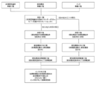
- FIG. 2 is a process diagram illustrating an example of an image recording method according to the present disclosure.
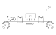
- 1 is a schematic configuration diagram conceptually illustrating an example of an image recording apparatus suitable for performing an image recording method according to the present disclosure.
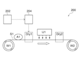
- 1 is a schematic configuration diagram conceptually illustrating an example of an image recording system of the present disclosure.
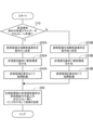
- 5 is a flowchart illustrating an example of a control routine in an example of an image recording system according to the present disclosure.
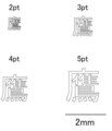
- FIG. 7 is a diagram conceptually illustrating a character image used for evaluating image bleeding in the example.
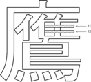
- FIG. 7 is a diagram for explaining details of evaluation criteria for image bleeding in the example.
- a numerical range represented by using “to” means a range including numerical values described before and after “to” as a lower limit and an upper limit.
- the amount of each component in the composition, when there are a plurality of substances corresponding to each component in the composition, unless otherwise specified, means the total amount of the plurality of substances present in the composition I do.
- the upper limit or lower limit described in a certain numerical range may be replaced with the upper limit or lower limit of the numerical range described in other stages, Further, the values may be replaced with the values shown in the embodiment.
- step is included in the term, not only as an independent step but also as long as the intended purpose of the step is achieved even when it cannot be clearly distinguished from other steps.
- a combination of preferred embodiments is a more preferred embodiment.
- the image recording method includes: A step of preparing a non-permeable base material (hereinafter, also referred to as a “non-permeable base material preparation step”); A step of preparing a pretreatment liquid containing water and a coagulant (hereinafter, also referred to as a “pretreatment liquid preparation step”); Step of preparing an ink containing water and a colorant (hereinafter, also referred to as “ink preparation step”)
- a step of determining whether the surface energy of the non-permeable substrate is less than 50 mN / m or 50 mN / m or more hereinafter, also referred to as a “determination step”
- the heating and drying conditions for heating and drying the pretreatment liquid are set after heating and drying with respect to the mass of the pretreatment liquid before heating and drying.
- the pretreatment liquid is heated and dried.
- the pretreatment liquid application step A step of applying a pretreatment liquid to the non-permeable substrate
- a step of heating and drying the pretreatment liquid applied to the non-permeable substrate under the heating and drying conditions set in the determination step (hereinafter, also referred to as a “pretreatment liquid heating and drying step”); Applying an ink to at least a part of the pre-treatment liquid application surface of the non-permeable base material after heating and drying to record an image
- the image recording method of the present disclosure it is possible to record an image on which streaking and bleeding are suppressed on a non-permeable base material.
- the reason for such an effect is assumed as follows.
- the image recording method of the present disclosure is not limited by the following reasons.
- the image recording method of the present disclosure determines heating and drying conditions for heating and drying the pretreatment liquid according to the surface energy of the non-permeable substrate. Thereby, streaks and bleeding of the image are suppressed.
- the heating and drying conditions for heating and drying the pretreatment liquid are set to the mass of the pretreatment liquid before heating and drying. Is determined as the condition A in which the percentage of the mass of the pretreatment liquid after heating and drying (hereinafter, also referred to as the mass ratio of the pretreatment liquid [after drying / before drying]) is 30% or more.
- the pre-produced non-permeable base material, pretreatment liquid, or ink is used in this example. May simply be a step of preparing for the image recording method according to the present invention, or may be a step of producing a non-permeable base material, a pretreatment liquid, or an ink.
- the order of the non-permeable base material preparation step, the pretreatment liquid preparation step, and the ink preparation step is not particularly limited.
- non-permeable substrate means a substrate having a water absorption of 0.3 g / m 2 or less.
- the amount of water absorption (g / m 2 ) of the substrate is measured as follows. Water is brought into contact with an area of 100 mm ⁇ 100 mm on the front surface of the base material (that is, the surface to which the pretreatment liquid is applied), and the state is maintained at 25 ° C. for 1 minute. The mass (absorbed amount (g)) of the water absorbed by the holding for one minute is determined, and the obtained absorbed amount (g) is converted into the absorbed amount per unit area (g / m 2 ).
- the shape of the resin substrate is not particularly limited, but is preferably a sheet shape, and more preferably a long sheet shape.
- the roll can be formed by winding, which is advantageous in terms of productivity when manufacturing the resin base material and speeding up of image recording. It is.
- the thickness of the sheet-shaped resin substrate is preferably from 10 ⁇ m to 200 ⁇ m, more preferably from 10 ⁇ m to 100 ⁇ m.
- Examples of the surface treatment include, but are not limited to, corona treatment, plasma treatment, flame treatment, heat treatment, abrasion treatment, light irradiation treatment (UV treatment), and flame treatment.
- the corona treatment can be performed using, for example, a corona master (PS-10S, manufactured by Shinko Electric Meter Co., Ltd.).
- the pretreatment liquid preparation step is a step of preparing a pretreatment liquid containing water and a flocculant.
- the pretreatment liquid preparation step may be a step of simply preparing a pretreatment liquid prepared in advance (that is, manufactured) for use in the image recording method of the present disclosure, or may prepare a pretreatment liquid. It may be a process.
- the solid content in the pretreatment liquid is preferably 30% by mass. Or less, more preferably 25% by mass or less, further preferably 20% by mass or less, and still more preferably 15% by mass or less.
- the solid content in the pretreatment liquid means the total amount of the pretreatment liquid excluding the solvent.
- the concept of the solvent includes at least water.
- the pretreatment liquid contains at least one coagulant.
- the coagulant exerts a function of coagulating components in the ink on the non-permeable base material. Thereby, the abrasion resistance of the image recorded on the non-permeable substrate is improved.
- the organic compound having a carboxy group is preferably a divalent or higher carboxylic acid (hereinafter, also referred to as a polyvalent carboxylic acid), and more preferably a dicarboxylic acid, from the viewpoint of the aggregation speed of the ink.
- a dicarboxylic acid malonic acid, malic acid, maleic acid, succinic acid, glutaric acid, pimelic acid, fumaric acid, tartaric acid, 4-methylphthalic acid or citric acid are more preferable, and malonic acid, malic acid, glutaric acid, pimerin Acids, tartaric acid or citric acid are more preferred.
- a metal complex containing at least one selected from the group consisting of zirconium, aluminum, and titanium as a metal element is preferable.
- a ligand is selected from the group consisting of acetate, acetylacetonate, methylacetoacetate, ethylacetoacetate, octylene glycolate, butoxyacetylacetonate, lactate, lactate ammonium salt, and triethanolaminate.
- metal complexes are commercially available as metal complexes, and in the present disclosure, commercially available metal complexes may be used. Also, various organic ligands, especially various polydentate ligands capable of forming metal chelate catalysts, are commercially available. Therefore, a metal complex prepared by combining a commercially available organic ligand and a metal may be used.
- water-soluble refers to a property that can be dissolved in water at a certain concentration or more.
- water-soluble in the present disclosure, a property of dissolving 5 g or more (more preferably 10 g or more) in 100 g of water at 25 ° C. is preferable.
- the content of the flocculant in the pretreatment liquid is not particularly limited. From the viewpoint of the aggregation speed of the ink, the content of the aggregation agent with respect to the total amount of the pretreatment liquid is preferably 0.1% by mass to 30% by mass, more preferably 1% by mass to 20% by mass, and further preferably Is from 1% by mass to 10% by mass, more preferably from 1% by mass to 8% by mass.
- the weight average molecular weight (Mw) of the resin that can be contained in the pretreatment liquid is preferably from 1,000 to 300,000, more preferably from 2,000 to 200,000, further preferably from 5,000 to 100,000.
- the weight average molecular weight means a value measured by gel permeation chromatography (GPC) unless otherwise specified.
- the measurement by gel permeation chromatography (GPC) uses HLC (registered trademark) -8020GPC (Tosoh Corporation) as a measuring device and TSKgel (registered trademark) Super Multipore HZ-H (4.6 mm ID ⁇ ) as a column. 15 cm, Tosoh Corporation), and THF (tetrahydrofuran) is used as an eluent.
- the measurement is performed using a RI detector with a sample concentration of 0.45% by mass, a flow rate of 0.35 ml / min, a sample injection amount of 10 ⁇ l, and a measurement temperature of 40 ° C.
- the calibration curve is “Standard sample TSK standard, polystyrene” of Tosoh Corporation: “F-40”, “F-20”, “F-4”, “F-1”, “A-5000”, “A -2500 ",” A-1000 ", and” n-propylbenzene ".
- the resin that can be contained in the pretreatment liquid preferably has an alicyclic structure or an aromatic ring structure, and more preferably has an aromatic ring structure.
- an alicyclic hydrocarbon structure having 5 to 10 carbon atoms is preferable, and a cyclohexane ring structure, a dicyclopentanyl ring structure, a dicyclopentenyl ring structure, or an adamantane ring structure is preferable.
- the aromatic ring structure a naphthalene ring or a benzene ring is preferable, and a benzene ring is more preferable.
- the amount of the alicyclic structure or the aromatic ring structure is not particularly limited, and is, for example, preferably 0.01 mol to 1.5 mol, more preferably 0.1 mol to 1 mol, per 100 g of the resin.
- the resin that can be contained in the pretreatment liquid preferably has an ionic group.
- the ionic group may be an anionic group or a cationic group, but is preferably an anionic group from the viewpoint of easy introduction.
- the anionic group is not particularly limited, but is preferably a carboxy group or a sulfo group, and more preferably a sulfo group.
- the amount of the ionic group is not particularly limited, and is preferably from 0.001 mol to 1.0 mol, more preferably from 0.01 mol to 0.5 mol, per 100 g of the resin.
- the form of the resin that can be contained in the pretreatment liquid is preferably resin particles.
- the resin in the resin particles is preferably a water-insoluble resin.
- water-insoluble refers to a property of dissolving less than 1.0 g (more preferably less than 0.5 g) in 100 g of water at 25 ° C.
- the volume average particle size of the resin particles described above is preferably from 1 nm to 300 nm, more preferably from 3 nm to 200 nm, even more preferably from 5 nm to 150 nm.
- the volume average particle size means a value measured by a laser diffraction / scattering particle size distribution meter.
- a particle size distribution measuring device “Microtrack MT-3300II” manufactured by Nikkiso Co., Ltd.
- a commercial product of an aqueous dispersion of resin particles may be used as a raw material.
- the aqueous dispersion of the resin particles include Pesresin A124GP, Pesresin A645GH, Pesresin A613GE, Pesresin A615GE (all manufactured by Takamatsu Yushi Co., Ltd.), Eastek 1100, Eastek 1200 (all manufactured by Eastman Chemical), Pluscoat RZ570, Plus Coat Z687, Plus Coat Z565, Plus Coat RZ570, Plus Coat Z690 (manufactured by Taiyo Chemical Industry Co., Ltd.), Vironal MD1200 (manufactured by Toyobo Co., Ltd.), EM57DOC (manufactured by Daicel Finechem), and the like.
- the resin particles are preferably at least one selected from the group consisting of acrylic resin particles, polyester resin particles, and composite resin particles containing an acrylic resin and a polyester resin.
- the acrylic resin particles mean particles containing an acrylic resin and not containing a polyester resin in one particle.
- the proportion of the acrylic resin in the acrylic resin particles is preferably 90% by mass or more.
- the polyester resin particles mean particles containing a polyester resin and not containing an acrylic resin in one particle.
- the proportion of the polyester resin in the polyester resin particles is preferably 90% by mass or more.
- the composite resin particles containing an acrylic resin and a polyester resin mean particles containing both the acrylic resin and the polyester resin in one particle.
- the total ratio of the acrylic resin and the polyester resin in the composite resin particles is preferably 90% by mass or more.
- the specific mode of the composite resin particles is not particularly limited.
- a specific embodiment of the composite resin particles for example, an embodiment in which a polymer chain of an acrylic resin and a polymer chain of a polyester resin are entangled with each other is exemplified.
- a method for producing the composite resin particles for example, a method of mixing an aqueous dispersion of a polyester resin and an aqueous dispersion of an acrylic resin having a glycidyl group; in the aqueous dispersion of the polyester resin, having a glycidyl group
- known literature such as Japanese Patent Application Laid-Open No. 2010-143955 can be referred to.
- aqueous dispersions of the composite resin particles include the above-mentioned Pesresin A613GE and Pesresin A615GE.
- the glass transition temperature of the resin particles contained in the pretreatment liquid (hereinafter, also referred to as “T gp ”) and the ink described below
- T gi glass transition temperature of the resin particles contained in the pretreatment liquid
- the relationship between the glass transition temperature (hereinafter, also referred to as “T gi ”) of the contained resin particles is not particularly limited, but is, for example, ⁇ 100 ° C. ⁇ T gi ⁇ T gp , preferably 0 ° C. ⁇ T gi ⁇ T gp (ie, T gp ⁇ T gi ), more preferably 20 ° C. ⁇ T gi ⁇ T gp , and still more preferably 30 ° C.
- T gi -T gp there is no particular upper limit for T gi -T gp , but the upper limit is preferably 100 ° C.
- T gp is preferably 0 ° C. or higher (that is, 0 ° C. ⁇ T gp is satisfied), more preferably 10 ° C. or higher, and still more preferably 20 ° C. or higher, from the viewpoint of the suitability for production of the resin particles. And more preferably 30 ° C. or higher.
- the upper limit of T gp is preferably 150 ° C., and more preferably 100 ° C., from the viewpoint of further improving the adhesion of the image.
- the glass transition temperature of the resin particles means a value measured using differential scanning calorimetry (DSC).
- DSC differential scanning calorimetry
- the specific measurement of the glass transition temperature is performed according to the method described in JIS K 7121 (1987) or JIS K 6240 (2011).
- the glass transition temperature in the present disclosure is an extrapolated glass transition onset temperature (hereinafter sometimes referred to as Tig).
- Tig extrapolated glass transition onset temperature
- the method for measuring the glass transition temperature will be described more specifically.
- the temperature is maintained at about 50 ° C. lower than the expected glass transition temperature of the resin particles until the apparatus is stabilized, and then the heating rate is 20 ° C./min. Heat to about 30 ° C. higher and generate a Differential Thermal Analysis (DTA) or DSC curve.
- DTA Differential Thermal Analysis
- the extrapolated glass transition onset temperature that is, the glass transition temperature in the present disclosure, is defined as a straight line obtained by extending a low-temperature-side baseline to a high-temperature side in a DTA curve or a DSC curve, and a curve of a stepwise change portion of the glass transition. Determined as the temperature at the intersection with the tangent drawn at the point where the gradient is maximum.
- the glass transition temperature (T gp ) of the resin particles contained in the pretreatment liquid is determined by the glass transition temperature of the individual resin particles contained in the pretreatment liquid. It means the weighted average of the transition temperatures.
- T gp ⁇ T gi is further satisfied from the viewpoint of further improving the adhesion of the image and the abrasion resistance of the image.
- the more preferable aspects of the relationship between P i and P p and the relationship between T gp and T gi are as described above.
- the pretreatment liquid may contain, as the resin, a water-insoluble resin (for example, the resin particles described above) and a water-soluble resin other than the water-soluble cationic polymer.
- a water-soluble cationic polymer is intended to be encompassed by the concept of “flocculant” rather than “resin”.
- the water-soluble resin other than the water-soluble cationic polymer and known water-soluble resins such as polyvinyl alcohol, polyacrylamide, polyvinylpyrrolidone, and polyethylene glycol (excluding those corresponding to the water-soluble cationic polymer) ) Can be used.
- water-soluble polymer compounds (excluding those corresponding to water-soluble cationic polymers) described in paragraphs 0026 to 0080 of JP-A-2013-001854 are also suitable.
- polyhydric alcohols or polyhydric alcohol ethers are preferable, and alkanediols, polyalkylene glycols, or polyalkylene glycol ethers are more preferable from the viewpoint of suppressing the transfer of components.
- the content of the surfactant in the pretreatment liquid is not particularly limited, but may be such that the surface tension of the pretreatment liquid is 50 mN / m or less.
- the content is 20 mN / m to 50 mN / m, and more preferably, the content is 30 mN / m to 45 mN / m.
- the content of the surfactant as an antifoaming agent is preferably 0.0001% by mass to 1% by mass based on the total amount of the pretreatment liquid. , 0.001% by mass to 0.1% by mass.
- the pH of the pretreatment liquid at 25 ° C. is preferably from 0.1 to 3.5 from the viewpoint of the aggregation speed of the ink.
- the pH of the pretreatment liquid is 0.1 or more, the roughness of the non-permeable substrate is further reduced, and the adhesion of the image area is further improved.
- the pH of the pretreatment liquid is 3.5 or less, the aggregation speed is further improved, coalescence of dots (ink dots) by ink on the non-permeable substrate is further suppressed, and the roughness of the image is further reduced.
- the pH (25 ° C.) of the pretreatment liquid is more preferably from 0.2 to 2.0.
- the surface tension of the pretreatment liquid at 25 ° C. is preferably 60 mN / m or less, more preferably 20 mN / m to 50 mN / m, and further preferably 30 mN / m to 45 mN / m.
- the surface tension of the pretreatment liquid is measured by a plate method using an Automatic Surface Tensiometer CBVP-Z (manufactured by Kyowa Interface Science Co., Ltd.).
- the ink preparation step is a step of preparing an ink containing water and a colorant.
- the ink preparation step may be a step of merely preparing ink prepared in advance (that is, manufactured) for use in the image recording method of the present disclosure, or may be a step of preparing an ink. .
- In the ink preparation step only one kind of the ink may be prepared, or two or more kinds of the inks may be applied. When two or more colors of ink are prepared in the ink preparation step, image recording using two or more colors of ink becomes possible.
- the ink contains water.
- the water content is preferably at least 50% by mass, more preferably at least 60% by mass, based on the total amount of the ink.
- the upper limit of the water content in the ink varies depending on the content of the colorant and other components contained as needed.
- the upper limit of the water content in the ink is, for example, 90% by mass, and preferably 80% by mass, based on the total amount of the ink.
- the ink contains at least one colorant.
- the colorant is not particularly limited, and a known colorant can be used, but an organic pigment or an inorganic pigment is preferable.
- the mixing mass ratio (p: s) of the colorant (p) and the dispersant (s) is preferably in the range of 1: 0.06 to 1: 3, and more preferably in the range of 1: 0.125 to 1: 2. More preferably, the ratio is more preferably 1: 0.125 to 1: 1.5.
- the proportion of the acrylic resin particles in the entire resin particles contained in the ink is preferably 60% by mass or more, more preferably 80% by mass or more. , More preferably 90% by mass or more.
- the ratio of the acrylic resin particles to the entire resin particles contained in the ink is 60% by mass or more, the adhesion of the image is further improved.
- the glass transition temperature (T gi ) of the resin particles contained in the ink is not particularly limited, but is preferably 150 ° C. or lower, more preferably 130 ° C. or lower, from the viewpoint of the suitability for manufacturing the resin particles.
- the lower limit of T gi is not particularly limited, but is, for example, 50 ° C., and preferably 80 ° C.
- the surface energy of the non-permeable substrate is determined by the method of Owens-Wendt. Measure. Specifically, the contact angle of pure water to the surface of the sample cut from the non-permeable substrate, the contact angle of diiodomethane to the surface, and the contact angle of ethylene glycol to the surface are measured. The measurement of these contact angles is performed using, for example, a solid-liquid interface analyzer “Drop Master 500” manufactured by Kyowa Interface Science Co., Ltd.
- the pretreatment liquid heating and drying step is a step of heating and drying the pretreatment liquid applied to the non-permeable substrate under the heating and drying conditions set in the determination step (that is, condition A or condition B).
- condition A the heating and drying conditions set in the determination step
- condition B Each of the condition A and the condition B is as described above.
- the applied ink may be dried by heating to obtain an image.
- the means for heating and drying include known heating means such as a heater, known air blowing means such as a dryer, and means combining these.
- a method for heating and drying the ink for example, a method in which heat is applied by a heater or the like from the side opposite to the surface on which the ink of the non-permeable substrate is applied, or the ink of the non-permeable substrate is applied.
- the methods and conditions exemplified in the section of “Image Recording Method” can be applied.
- the method and conditions exemplified in the description of the “image recording method” can be applied to the drying method and conditions in the pretreatment liquid drying zone Dry1.
- the methods and conditions exemplified in the section of the step of applying the ink can be applied.
- the method and conditions exemplified in the step of applying the ink can be applied to the drying method and conditions in the ink drying zone Dry2.
- the structure of the ink applying device IJ1 includes at least two of the above four line heads, and the two or more line heads are arranged in the direction of transport of the non-permeable substrate (the direction of the block arrow).
- the structure is arranged.
- the ink applying device IJ1 further includes a line head for white ink, a line head for orange ink, a line head for green ink, a line head for purple ink, a line head for light cyan ink, and a line head for light magenta ink. At least one line head among the heads may be provided.
- an operator determines the surface energy of the non-permeable substrate S1 in the determination step, and determines the heating and drying conditions of the pretreatment liquid in the determination step.
- the operator can set specific heating / drying conditions (for example, drying temperature, drying time, Etc.) manually.
- the image recording system of the present disclosure includes: A determining unit that determines whether the surface energy of the non-permeable substrate is less than 50 mN / m or 50 mN / m or more; When it is determined that the surface energy of the non-permeable base material is less than 50 mN / m, the heating and drying conditions for heating and drying the pretreatment liquid are set after heating and drying with respect to the mass of the pretreatment liquid before heating and drying.
- FIG. 3 is a schematic configuration diagram conceptually showing an image recording system 200 which is an example of the image recording system of the present disclosure.
- the configuration of the image recording system 200 is the same as the configuration of the image recording apparatus 100 shown in FIG. 2 described above, except that a determination unit 202 and a determination unit 204 are added.
- the determination unit 204 determines whether the heating and drying conditions for heating and drying the pretreatment liquid are the condition A or the condition B based on the determination result transmitted from the determination unit 202. Information on the heating and drying conditions (that is, condition A or condition B) determined by the determination unit 204 is transmitted to the pretreatment liquid drying zone Dry1.
- FIG. 4 is a flowchart illustrating an example of a control routine in the image recording system 200. This routine starts when the power of the image recording system 200 is turned on. First, in step 210, the determination unit 202 determines whether the surface energy of the non-permeable base material S1 is less than 50 mN / m.
- step 210 If it is determined in step 210 that the surface energy of the non-permeable base material S1 is less than 50 mN / m, the process proceeds to step 220A.
- step 220A the heating / drying condition of the pretreatment liquid is determined to be condition A by the determination unit 204, and then, in step 230A, the pretreatment liquid is applied to the non-permeable substrate by the pretreatment liquid application device A1, In step 240A, the pretreatment liquid is heated and dried under the condition A in the pretreatment liquid drying zone Dry1.
- aqueous dispersion of resin particles for preparation of pretreatment liquid As a water dispersion of the resin particles for preparing the pretreatment liquid, "Pesresin A615GE" (a water dispersion of the composite resin particles AE1 containing an acrylic resin and a polyester resin) manufactured by Takamatsu Oil & Fats Co., Ltd. was prepared. Glass transition temperature T gp composite resin particles AE1 is 47 ° C., a volume-average particle size P P of the composite resin particles AE1 is 45 nm. The mass ratio [polyester resin / acrylic resin] in the composite resin particles AE1 is 0.9.
- Glass transition temperature T gi of acrylic resin particles IA-1 is 120 ° C.
- a volume-average particle size P i of the acrylic resin particles IA-1 is 10 nm.
- Example 1 Image recording was performed using the image recording apparatus 100 shown in FIG.
- the transport speed of the non-permeable substrate S1 (that is, the traveling speed of the non-permeable substrate S1) was 635 mm / sec.
- a wire bar coater was used as the pretreatment liquid applying device A1.
- the drying method in the pretreatment liquid drying zone Dry1 was hot air drying.
- the ink jet head and the ink discharge conditions in the ink applying device IJ1 were as follows.
- -Ink jet head A piezo full line head (total number of nozzles: 2048) using 1200 dpi (dot per inch, 2.54 cm for 1 inch) / 20 inch width was used.
- -Ink droplet volume 2.4 pL for each. Drive frequency: 30 kHz.
- the drying method in the ink drying zone Dry2 was hot air drying.
- a roll body in which a non-permeable substrate S1 having a thickness of 25 ⁇ m, a width of 500 mm, and a length of 2000 m (a biaxially stretched polypropylene substrate “P2161” manufactured by Toyobo; hereinafter also referred to as “OPP”) is wound into a roll.
- OPP biaxially stretched polypropylene substrate “P2161” manufactured by Toyobo; hereinafter also referred to as “OPP”
- roll body 1 When the non-permeable base material S1 was unwound from the roll body 1 and the surface energy was measured, it was 40 mN / m.
- Example 1 Based on the determination result of the surface energy of the non-permeable base material S1, the conditions for heating and drying the pretreatment liquid in the pretreatment liquid drying zone Dry1 were determined.
- the heating and drying conditions for the pretreatment liquid were such that the mass ratio of the pretreatment liquid [after drying / before drying] was "Condition A" was determined to be 30% or more.
- Specific values of the mass ratio of the pretreatment liquid [after drying / before drying] are as shown in Table 2.
- Example 1 as the condition A, the conditions for heating and drying the pretreatment liquid in the pretreatment liquid drying zone Dry1 were set to the following specific conditions.
- the roll body 1 (that is, the roll body on which the non-permeable substrate S1 was wound) was set in the unwinding device W1. Further, the pretreatment liquid described above was set in the pretreatment liquid application device A1, and the cyan ink was set in the ink application device IJ1.
- the non-permeable base material S1 was unwound from the roll body 1 by the unwinding device W1, and the unwound non-permeable base material S1 was transported at the above-described transport speed.
- the applied mass per unit area (that is, the amount of the pre-treatment liquid before drying) is set such that the above-mentioned pre-treatment liquid is applied to one surface of the non-permeable base material S1 being transported by the pre-treatment liquid application device A1. Coating was performed so as to be 8 g / m 2 .
- the applied pretreatment liquid was heated and dried in the pretreatment liquid drying zone Dry1 under the condition A described above.
- the above-described cyan ink was applied to a part of the pretreatment liquid application surface (that is, the entire one surface) of the non-permeable base material S1 after the heating and drying by the ink jetting method using the ink application device IJ1.
- the region to which the cyan ink was applied was a band-like region having a width of 250 mm centered on the central portion in the width direction among the total width of 500 mm of the non-permeable base material S1.
- the applied mass of the cyan ink per unit area in the area where the cyan ink was applied was 3 g / m 2 .
- the applied cyan ink was dried at 80 ° C. for 8 seconds in the ink drying zone Dry2.
- a cyan solid image was recorded on the entire belt-shaped region having a width of 250 mm.
- Each of the 125-mm-wide regions at each of both ends in the width direction of the non-permeable substrate S1 is an image non-recording region.
- the non-permeable substrate S1 on which the cyan solid image was recorded (that is, the image-recorded material) was wound by the winding device W2 under the condition that the winding pressure (surface pressure) became 50 kPa.
- the wound image recorded matter is hereinafter referred to as “roll body 2”.
- the image recorded matter was unwound from the roll 2, and the following evaluations were performed using the unwound image recorded matter.
- the tape was taken out at a constant speed and cut into a length of about 75 mm to obtain a tape piece.
- the obtained tape piece was superimposed on a cyan solid image, and an area having a width of 18 mm and a length of 25 mm at the center of the tape piece was stuck with a finger and rubbed firmly with a fingertip.
- the end of the tape piece was grasped and peeled at an angle as close as possible to 60 ° for 0.5 to 1.0 seconds.
- Examples 2, 3, 6, and 7 The same operation as in Example 1 was performed except that the specific heating and drying conditions of the pretreatment liquid as the condition A were changed as shown in Table 2. Table 2 shows the results.
- Examples 4 and 5 The same operation as in Example 3 was performed except that the type of the coagulant in the pretreatment liquid was changed as shown in Table 2. Table 2 shows the results.
- Examples 4 and 5 Details of the flocculants in Examples 4 and 5 are as follows.
- CaCl 2 calcium chloride (polyvalent metal salt) manufactured by Fujifilm Wako Pure Chemical Industries, Ltd.
- -Cationic polymer A poly-2-hydroxypropyldimethylammonium chloride (Kachiomata (registered trademark) PD-7 manufactured by Yokkaichi Gosei Co., Ltd.)
- Example 8 In the preparation of the pretreatment liquid, the same operation as in Example 3 was performed except that no resin particles were used. Table 2 shows the results.
- the surface energy of the non-permeable substrate was less than 50 mN / m, and the heating and drying conditions of the pretreatment liquid were determined to be "condition A".
- Specific values of the mass ratio of the pretreatment liquid [after drying / before drying] and specific heating and drying conditions as the condition A are as shown in Table 2, respectively.
- Example 10 Same as Example 3 except that the type of the non-permeable base material was changed to a polyethylene base material (“LL-RP2” manufactured by Futamura Chemical Co., Ltd., thickness: 30 ⁇ m) (hereinafter, also referred to as “PE”). The operation was performed. Table 2 shows the results.
- the surface energy of the non-permeable substrate was determined to be less than 50 mN / m based on the measured value of the surface energy of the non-permeable substrate (see Table 2).
- the condition was determined to be “condition A”. Specific values of the mass ratio of the pretreatment liquid [after drying / before drying] and specific heating and drying conditions as the condition A are as shown in Table 2, respectively.
- Example 11 The type of non-permeable base material was changed to a polyethylene terephthalate base material (“FE2001” manufactured by Futamura Chemical Co., Ltd., thickness 25 ⁇ m) (hereinafter also referred to as “PET”), and the following points were changed. Except for the above, the same operation as in Example 1 was performed. Table 2 shows the results.
- PET polyethylene terephthalate base material
- Example 11 since the surface energy of the non-permeable substrate was 55 mN / m, it was determined that the surface energy of the non-permeable substrate was 50 mN / m or more. Therefore, the heating and drying conditions for the pretreatment liquid were determined to be "condition B" in which the mass ratio [after drying / before drying] of the pretreatment liquid was less than 50%. Specific values of the mass ratio of the pretreatment liquid [after drying / before drying] are as shown in Table 2. In Example 11, as the condition B, the conditions for heating and drying the pretreatment liquid in the pretreatment liquid drying zone Dry1 were set to the following specific conditions. Under the set heating and drying conditions, the pretreatment liquid was heated and dried in the pretreatment liquid drying zone Dry1.
- condition B- ⁇ Drying temperature 60 ° C ⁇ Drying time: 6 seconds
- Example 12 [Examples 12, 15, 16, and 17] The same operation as in Example 11 was performed except that the specific heating and drying conditions of the pretreatment liquid as the condition B were changed as shown in Table 2. Table 2 shows the results.
- Example 13 and 14 The same operation as in Example 12 was performed except that the type of the coagulant in the pretreatment liquid was changed as shown in Table 2. Table 2 shows the results.
- the flocculants (CaCl 2 and cationic polymer A) in Examples 13 and 14 are the same as the flocculants in Examples 4 and 5, respectively.
- Example 18 In the preparation of the pretreatment liquid, the same operation as in Example 12 was performed except that no resin particles were used. Table 2 shows the results.
- Example 19 The same operation as in Example 12 was performed except that the surface of the non-permeable base material to which the treatment liquid was applied was subjected to corona treatment on the upstream side of the pretreatment liquid application device A1 in the transport direction. Table 2 shows the results.
- the conditions for the corona treatment in the nineteenth embodiment are the same as the conditions for the corona treatment in the ninth embodiment.
- a non-permeable substrate separately subjected to only the corona treatment under the above conditions was prepared, and the surface energy of the corona-treated surface of the non-permeable substrate was measured.
- Example 20 The same operation as in Example 12 was performed except that the type of the non-permeable base material was changed to a nylon base material (“Emblem ON-25” manufactured by Unitika Ltd., thickness 25 ⁇ m) (hereinafter also referred to as “NY”). went. Table 2 shows the results.
- the surface energy of the non-permeable substrate was determined to be 50 mN / m or more based on the measured value of the surface energy of the non-permeable substrate (see Table 2).
- the condition was determined to be "condition B". Specific values of the mass ratio of the pretreatment liquid [after drying / before drying] and specific heating and drying conditions as the condition B are as shown in Table 2, respectively.
- Table 2 shows specific heating and drying conditions of the pretreatment liquid. The same operation as in Example 1 was performed except that the specific heating and drying conditions were changed to Condition B. Table 2 shows the results.
- Table 2 shows specific heating and drying conditions of the pretreatment liquid. The same operation as in Example 11 was performed except that the specific heating and drying conditions were changed to Condition A. Table 2 shows the results.
- the condition that the surface energy of the non-permeable substrate is less than 50 mN / m and the mass ratio of the pretreatment liquid [after drying / before drying] is 30% or more.
- Examples 1 to 10 which were heated and dried in A, and the surface energy of the non-permeable substrate is 50 mN / m or more, and the pretreatment liquid is the mass ratio of the pretreatment liquid [after drying / before drying] In Examples 11 to 20 in which heating and drying were performed under the condition B in which the content was less than 50%, the streaking of the image and the bleeding of the image were suppressed.
- the surface energy of the non-permeable substrate is less than 50 mN / m, and the pretreatment liquid is heated and dried under the condition that the mass ratio [after drying / before drying] of the pretreatment liquid is less than 30%.
- the pretreatment liquid was heated and dried under the condition that the mass ratio [after drying / before drying] of the pretreatment liquid was 50% or more.
- the embodiments using cyan ink as the ink have been described.
- the cyan ink is changed to an ink other than cyan ink (for example, magenta ink, yellow ink, black ink, etc.).
- an ink other than cyan ink for example, magenta ink, yellow ink, black ink, etc.
- the same effect as that of the above-described embodiment group can be obtained.
- a person made the determination in the determination step and the determination in the determination step using an image recording apparatus without a determination unit and a determination unit.
- the apparatus performs the determination in the determination step and the determination in the determination step using the image recording system of the present disclosure including the determination unit and the determination unit, it is possible to obtain the same effect as the above-described example group. Needless to say.
- Image recording device 200
- Image recording system 202
- Pretreatment liquid application device Dry1 pretreatment liquid drying zone IJ1 Ink applying device Dry2 ink drying zone W2 winding device
Landscapes
- Chemical & Material Sciences (AREA)
- Life Sciences & Earth Sciences (AREA)
- Engineering & Computer Science (AREA)
- Materials Engineering (AREA)
- Wood Science & Technology (AREA)
- Organic Chemistry (AREA)
- Chemical Kinetics & Catalysis (AREA)
- Ink Jet (AREA)
- Ink Jet Recording Methods And Recording Media Thereof (AREA)
- Inks, Pencil-Leads, Or Crayons (AREA)
Abstract
L'invention concerne un procédé d'enregistrement d'image et un système d'enregistrement d'image avec lesquels des images présentant des stries minimales et un flou minimal peuvent être enregistrées sur un matériau de base imperméable. Ce procédé d'enregistrement d'image comprend les étapes consistant : à déterminer si oui ou non l'énergie de surface d'un matériau de base est inférieure à 50 mN/m ou égale ou supérieure à 50 mN/m ; à établir qu'une condition de séchage d'un liquide de prétraitement contenant de l'eau et un floculant est une condition A, selon laquelle le rapport entre la masse du liquide de prétraitement après séchage et la même masse avant séchage est de 30 % ou plus, lorsqu'il est déterminé que l'énergie de surface est inférieure à 50 mN/m, et à établir que ladite condition de séchage est une condition B, selon laquelle ledit rapport de masse est inférieur à 50 %, lorsqu'il est déterminé que l'énergie de surface est égale ou supérieure à 50 mN/m ; à appliquer le liquide de prétraitement sur le matériau de base ; à sécher le liquide de prétraitement appliqué dans la condition de séchage établie comme décrit ci-dessus ; et à appliquer de l'encre contenant de l'eau et un agent colorant sur au moins une partie du matériau de base après séchage pour enregistrer une image.
Priority Applications (4)
| Application Number | Priority Date | Filing Date | Title |
|---|---|---|---|
| CN201980042955.4A CN112423992B (zh) | 2018-07-26 | 2019-06-11 | 图像记录方法及图像记录系统 |
| JP2020532204A JP6982185B2 (ja) | 2018-07-26 | 2019-06-11 | 画像記録方法及び画像記録システム |
| EP19842078.8A EP3827999B1 (fr) | 2018-07-26 | 2019-06-11 | Procédé d'enregistrement d'image et système d'enregistrement d'image |
| US17/120,270 US11338592B2 (en) | 2018-07-26 | 2020-12-14 | Image recording method and image recording system |
Applications Claiming Priority (2)
| Application Number | Priority Date | Filing Date | Title |
|---|---|---|---|
| JP2018-140545 | 2018-07-26 | ||
| JP2018140545 | 2018-07-26 |
Related Child Applications (1)
| Application Number | Title | Priority Date | Filing Date |
|---|---|---|---|
| US17/120,270 Continuation US11338592B2 (en) | 2018-07-26 | 2020-12-14 | Image recording method and image recording system |
Publications (1)
| Publication Number | Publication Date |
|---|---|
| WO2020021884A1 true WO2020021884A1 (fr) | 2020-01-30 |
Family
ID=69181008
Family Applications (1)
| Application Number | Title | Priority Date | Filing Date |
|---|---|---|---|
| PCT/JP2019/023001 Ceased WO2020021884A1 (fr) | 2018-07-26 | 2019-06-11 | Procédé d'enregistrement d'image et système d'enregistrement d'image |
Country Status (5)
| Country | Link |
|---|---|
| US (1) | US11338592B2 (fr) |
| EP (1) | EP3827999B1 (fr) |
| JP (1) | JP6982185B2 (fr) |
| CN (1) | CN112423992B (fr) |
| WO (1) | WO2020021884A1 (fr) |
Cited By (4)
| Publication number | Priority date | Publication date | Assignee | Title |
|---|---|---|---|---|
| WO2022219954A1 (fr) * | 2021-04-16 | 2022-10-20 | 株式会社ミマキエンジニアリング | Procédé d'impression, dispositif d'impression et matière imprimée |
| JP2022164336A (ja) * | 2021-04-16 | 2022-10-27 | 株式会社ミマキエンジニアリング | 印刷方法、印刷装置及び印刷物 |
| JP2022171431A (ja) * | 2021-04-30 | 2022-11-11 | 株式会社ミマキエンジニアリング | 印刷方法及び印刷装置 |
| WO2024166563A1 (fr) * | 2023-02-10 | 2024-08-15 | 富士フイルム株式会社 | Procédé d'impression d'image |
Families Citing this family (2)
| Publication number | Priority date | Publication date | Assignee | Title |
|---|---|---|---|---|
| CN118302300A (zh) * | 2021-11-25 | 2024-07-05 | 富士胶片株式会社 | 喷墨记录方法 |
| US12417518B2 (en) * | 2022-11-22 | 2025-09-16 | Adobe Inc. | Repairing irregularities in computer-generated images |
Citations (19)
| Publication number | Priority date | Publication date | Assignee | Title |
|---|---|---|---|---|
| JPS5459936A (en) | 1977-10-03 | 1979-05-15 | Canon Inc | Recording method and device therefor |
| JPS59157636A (ja) | 1983-02-25 | 1984-09-07 | Fuji Photo Film Co Ltd | カラ−画像形成方法 |
| JP2003306623A (ja) | 2002-04-16 | 2003-10-31 | Fuji Photo Film Co Ltd | 水性インク |
| JP2003322926A (ja) | 2002-05-02 | 2003-11-14 | Fuji Photo Film Co Ltd | ハロゲン化銀写真感光材料 |
| JP2004309806A (ja) | 2003-04-08 | 2004-11-04 | Fuji Photo Film Co Ltd | ハロゲン化銀写真感光材料 |
| JP2004325707A (ja) | 2003-04-24 | 2004-11-18 | Fuji Photo Film Co Ltd | ハロゲン化銀写真感光材料および水性塗布組成物 |
| JP2007098610A (ja) | 2005-09-30 | 2007-04-19 | Fujifilm Corp | インクジェット記録用媒体 |
| JP2009241586A (ja) | 2008-03-12 | 2009-10-22 | Fujifilm Corp | 画像記録方法、インクセット、及びインクジェット記録物 |
| JP2010005816A (ja) | 2008-06-24 | 2010-01-14 | Fujifilm Corp | インクジェット記録装置及び画像記録方法 |
| JP2010005996A (ja) * | 2008-06-30 | 2010-01-14 | Fujifilm Corp | インクジェット記録装置及び打滴検出方法 |
| JP2010076316A (ja) * | 2008-09-26 | 2010-04-08 | Fujifilm Corp | 画像形成方法及び画像形成装置 |
| JP2010143955A (ja) | 2008-12-16 | 2010-07-01 | Takamatsu Oil & Fat Co Ltd | 耐水性及び耐溶剤性を有する皮膜を形成する水分散性樹脂組成物 |
| JP2011042150A (ja) | 2009-08-24 | 2011-03-03 | Fujifilm Corp | 画像形成方法 |
| JP2013001854A (ja) | 2011-06-17 | 2013-01-07 | Fujifilm Corp | インクセット及び画像形成方法 |
| JP2013248883A (ja) * | 2012-05-01 | 2013-12-12 | Ricoh Co Ltd | 画像形成装置、画像形成方法及びその画像形成方法により生産した生産物、並びに、印刷物の印刷方法及びその印刷方法により印刷した印刷物 |
| JP2015039868A (ja) * | 2013-08-23 | 2015-03-02 | 富士フイルム株式会社 | 画像形成方法、及び画像形成装置 |
| JP2016145312A (ja) | 2015-01-29 | 2016-08-12 | 富士フイルム株式会社 | インクセット及び画像形成方法 |
| JP2016188345A (ja) | 2015-03-30 | 2016-11-04 | 富士フイルム株式会社 | インクジェット用顔料分散体及びその製造方法、インクセット、並びに画像形成方法 |
| JP2017094673A (ja) * | 2015-11-27 | 2017-06-01 | セイコーエプソン株式会社 | 液体噴射装置および液体噴射方法 |
Family Cites Families (10)
| Publication number | Priority date | Publication date | Assignee | Title |
|---|---|---|---|---|
| US6833008B2 (en) * | 2001-01-16 | 2004-12-21 | Aprion Digital Ltd. | Surface treatment for printing applications using water-based ink |
| US8042906B2 (en) * | 2007-09-25 | 2011-10-25 | Fujifilm Corporation | Image forming method and apparatus |
| EP2252467A1 (fr) * | 2008-02-06 | 2010-11-24 | Nano Terra Inc. | Pochoirs pour pellicules protectrices amovibles pour former des caractéristiques à l'échelle micrométrique sur des surfaces et leurs procédés de fabrication et d'utilisation |
| WO2013095332A1 (fr) * | 2011-12-19 | 2013-06-27 | Hewlett-Packard Development Company, L.P. | Fluides de prétraitement avec un réticulant chélate de métal d'ammonium pour des supports d'impression |
| WO2013132418A2 (fr) * | 2012-03-05 | 2013-09-12 | Landa Corporation Limited | Procédé d'impression numérique |
| JP2014034167A (ja) * | 2012-08-09 | 2014-02-24 | Ricoh Co Ltd | 画像形成方法 |
| DE102014224276B4 (de) * | 2014-11-27 | 2021-12-30 | Fraunhofer-Gesellschaft zur Förderung der angewandten Forschung e.V. | Verfahren zum hochpräzisen Drucken von Strukturen auf Oberflächen sowie Substrat mit einer eine gedruckte Struktur aufweisenden Oberfläche |
| US9376582B1 (en) * | 2015-07-30 | 2016-06-28 | Eastman Kodak Company | Printing on water-impermeable substrates with water-based inks |
| WO2017163738A1 (fr) * | 2016-03-24 | 2017-09-28 | 富士フイルム株式会社 | Jeu d'encres et procédé d'enregistrement d'image |
| EP3778249A4 (fr) * | 2018-03-30 | 2021-06-09 | FUJIFILM Corporation | Liquide de prétraitement, ensemble d'encres, matériau à image imprimée, substrat pour impression d'image, procédé de fabrication de substrat pour impression d'image et procédé d'impression d'image |
-
2019
- 2019-06-11 WO PCT/JP2019/023001 patent/WO2020021884A1/fr not_active Ceased
- 2019-06-11 CN CN201980042955.4A patent/CN112423992B/zh active Active
- 2019-06-11 EP EP19842078.8A patent/EP3827999B1/fr active Active
- 2019-06-11 JP JP2020532204A patent/JP6982185B2/ja active Active
-
2020
- 2020-12-14 US US17/120,270 patent/US11338592B2/en active Active
Patent Citations (19)
| Publication number | Priority date | Publication date | Assignee | Title |
|---|---|---|---|---|
| JPS5459936A (en) | 1977-10-03 | 1979-05-15 | Canon Inc | Recording method and device therefor |
| JPS59157636A (ja) | 1983-02-25 | 1984-09-07 | Fuji Photo Film Co Ltd | カラ−画像形成方法 |
| JP2003306623A (ja) | 2002-04-16 | 2003-10-31 | Fuji Photo Film Co Ltd | 水性インク |
| JP2003322926A (ja) | 2002-05-02 | 2003-11-14 | Fuji Photo Film Co Ltd | ハロゲン化銀写真感光材料 |
| JP2004309806A (ja) | 2003-04-08 | 2004-11-04 | Fuji Photo Film Co Ltd | ハロゲン化銀写真感光材料 |
| JP2004325707A (ja) | 2003-04-24 | 2004-11-18 | Fuji Photo Film Co Ltd | ハロゲン化銀写真感光材料および水性塗布組成物 |
| JP2007098610A (ja) | 2005-09-30 | 2007-04-19 | Fujifilm Corp | インクジェット記録用媒体 |
| JP2009241586A (ja) | 2008-03-12 | 2009-10-22 | Fujifilm Corp | 画像記録方法、インクセット、及びインクジェット記録物 |
| JP2010005816A (ja) | 2008-06-24 | 2010-01-14 | Fujifilm Corp | インクジェット記録装置及び画像記録方法 |
| JP2010005996A (ja) * | 2008-06-30 | 2010-01-14 | Fujifilm Corp | インクジェット記録装置及び打滴検出方法 |
| JP2010076316A (ja) * | 2008-09-26 | 2010-04-08 | Fujifilm Corp | 画像形成方法及び画像形成装置 |
| JP2010143955A (ja) | 2008-12-16 | 2010-07-01 | Takamatsu Oil & Fat Co Ltd | 耐水性及び耐溶剤性を有する皮膜を形成する水分散性樹脂組成物 |
| JP2011042150A (ja) | 2009-08-24 | 2011-03-03 | Fujifilm Corp | 画像形成方法 |
| JP2013001854A (ja) | 2011-06-17 | 2013-01-07 | Fujifilm Corp | インクセット及び画像形成方法 |
| JP2013248883A (ja) * | 2012-05-01 | 2013-12-12 | Ricoh Co Ltd | 画像形成装置、画像形成方法及びその画像形成方法により生産した生産物、並びに、印刷物の印刷方法及びその印刷方法により印刷した印刷物 |
| JP2015039868A (ja) * | 2013-08-23 | 2015-03-02 | 富士フイルム株式会社 | 画像形成方法、及び画像形成装置 |
| JP2016145312A (ja) | 2015-01-29 | 2016-08-12 | 富士フイルム株式会社 | インクセット及び画像形成方法 |
| JP2016188345A (ja) | 2015-03-30 | 2016-11-04 | 富士フイルム株式会社 | インクジェット用顔料分散体及びその製造方法、インクセット、並びに画像形成方法 |
| JP2017094673A (ja) * | 2015-11-27 | 2017-06-01 | セイコーエプソン株式会社 | 液体噴射装置および液体噴射方法 |
Non-Patent Citations (1)
| Title |
|---|
| D. K. OWENSR. C. WENDT, J. APPL. POLYM. SCI., vol. 13, 1969, pages 1741 |
Cited By (6)
| Publication number | Priority date | Publication date | Assignee | Title |
|---|---|---|---|---|
| WO2022219954A1 (fr) * | 2021-04-16 | 2022-10-20 | 株式会社ミマキエンジニアリング | Procédé d'impression, dispositif d'impression et matière imprimée |
| JP2022164336A (ja) * | 2021-04-16 | 2022-10-27 | 株式会社ミマキエンジニアリング | 印刷方法、印刷装置及び印刷物 |
| JP7664071B2 (ja) | 2021-04-16 | 2025-04-17 | 株式会社ミマキエンジニアリング | 印刷方法、印刷装置及び印刷物 |
| JP2022171431A (ja) * | 2021-04-30 | 2022-11-11 | 株式会社ミマキエンジニアリング | 印刷方法及び印刷装置 |
| JP7739038B2 (ja) | 2021-04-30 | 2025-09-16 | 株式会社ミマキエンジニアリング | 印刷方法及び印刷装置 |
| WO2024166563A1 (fr) * | 2023-02-10 | 2024-08-15 | 富士フイルム株式会社 | Procédé d'impression d'image |
Also Published As
| Publication number | Publication date |
|---|---|
| JP6982185B2 (ja) | 2021-12-17 |
| EP3827999B1 (fr) | 2024-10-09 |
| EP3827999A4 (fr) | 2021-10-13 |
| CN112423992B (zh) | 2022-03-22 |
| CN112423992A (zh) | 2021-02-26 |
| JPWO2020021884A1 (ja) | 2021-06-10 |
| US11338592B2 (en) | 2022-05-24 |
| US20210094325A1 (en) | 2021-04-01 |
| EP3827999A1 (fr) | 2021-06-02 |
Similar Documents
| Publication | Publication Date | Title |
|---|---|---|
| US20220289996A1 (en) | Pretreatment liquid for impermeable medium printing, method of producing base material for printing, image recording method, and ink set | |
| CN111727226B (zh) | 油墨组、图像记录方法、层合体的制造方法、图像记录物及层合体 | |
| JP7179964B2 (ja) | 非浸透性基材用インクジェットインク、画像記録方法、及びラミネート体の製造方法 | |
| JP6982185B2 (ja) | 画像記録方法及び画像記録システム | |
| JP6997201B2 (ja) | 画像形成方法及びインクセット | |
| CN113646176A (zh) | 油墨组、图像记录方法及图像记录物 | |
| JP7130114B2 (ja) | 画像形成方法 | |
| JP7371265B2 (ja) | 非浸透性基材用前処理液及びインクセット | |
| CN114174071B (zh) | 图像记录方法 | |
| JP7098664B2 (ja) | 被記録媒体の製造方法、及び、画像記録方法 | |
| CN112739546B (zh) | 预处理液、油墨组、图像记录用基材、图像记录用基材的制造方法、图像记录物及图像记录方法 | |
| JP7262575B2 (ja) | 非浸透性基材用前処理液、インクセット、画像記録方法、画像記録物、並びに、被記録媒体及びその製造方法 | |
| JP7354413B2 (ja) | 非浸透性基材用前処理液、及び画像記録方法 | |
| JPWO2020066461A1 (ja) | 前処理液、インクセット、画像記録用基材、画像記録用基材の製造方法、画像記録物、及び画像記録方法 |
Legal Events
| Date | Code | Title | Description |
|---|---|---|---|
| 121 | Ep: the epo has been informed by wipo that ep was designated in this application |
Ref document number: 19842078 Country of ref document: EP Kind code of ref document: A1 |
|
| ENP | Entry into the national phase |
Ref document number: 2020532204 Country of ref document: JP Kind code of ref document: A |
|
| NENP | Non-entry into the national phase |
Ref country code: DE |
|
| WWE | Wipo information: entry into national phase |
Ref document number: 2019842078 Country of ref document: EP |