WO2020021896A1 - Dispositif de stimulation de cellules, procédé de stimulation de cellules, procédé de production pour un produit de culture, procédé de production pour des cellules isolées, et procédé de prolifération cellulaire - Google Patents
Dispositif de stimulation de cellules, procédé de stimulation de cellules, procédé de production pour un produit de culture, procédé de production pour des cellules isolées, et procédé de prolifération cellulaire Download PDFInfo
- Publication number
- WO2020021896A1 WO2020021896A1 PCT/JP2019/023345 JP2019023345W WO2020021896A1 WO 2020021896 A1 WO2020021896 A1 WO 2020021896A1 JP 2019023345 W JP2019023345 W JP 2019023345W WO 2020021896 A1 WO2020021896 A1 WO 2020021896A1
- Authority
- WO
- WIPO (PCT)
- Prior art keywords
- cell
- electrode
- cells
- electric field
- solution
- Prior art date
- Legal status (The legal status is an assumption and is not a legal conclusion. Google has not performed a legal analysis and makes no representation as to the accuracy of the status listed.)
- Ceased
Links
Images














Classifications
-
- C—CHEMISTRY; METALLURGY
- C12—BIOCHEMISTRY; BEER; SPIRITS; WINE; VINEGAR; MICROBIOLOGY; ENZYMOLOGY; MUTATION OR GENETIC ENGINEERING
- C12M—APPARATUS FOR ENZYMOLOGY OR MICROBIOLOGY; APPARATUS FOR CULTURING MICROORGANISMS FOR PRODUCING BIOMASS, FOR GROWING CELLS OR FOR OBTAINING FERMENTATION OR METABOLIC PRODUCTS, i.e. BIOREACTORS OR FERMENTERS
- C12M35/00—Means for application of stress for stimulating the growth of microorganisms or the generation of fermentation or metabolic products; Means for electroporation or cell fusion
- C12M35/02—Electrical or electromagnetic means, e.g. for electroporation or for cell fusion
-
- C—CHEMISTRY; METALLURGY
- C12—BIOCHEMISTRY; BEER; SPIRITS; WINE; VINEGAR; MICROBIOLOGY; ENZYMOLOGY; MUTATION OR GENETIC ENGINEERING
- C12M—APPARATUS FOR ENZYMOLOGY OR MICROBIOLOGY; APPARATUS FOR CULTURING MICROORGANISMS FOR PRODUCING BIOMASS, FOR GROWING CELLS OR FOR OBTAINING FERMENTATION OR METABOLIC PRODUCTS, i.e. BIOREACTORS OR FERMENTERS
- C12M1/00—Apparatus for enzymology or microbiology
- C12M1/34—Measuring or testing with condition measuring or sensing means, e.g. colony counters
- C12M1/3407—Measure of electrical or magnetical factor
-
- C—CHEMISTRY; METALLURGY
- C12—BIOCHEMISTRY; BEER; SPIRITS; WINE; VINEGAR; MICROBIOLOGY; ENZYMOLOGY; MUTATION OR GENETIC ENGINEERING
- C12M—APPARATUS FOR ENZYMOLOGY OR MICROBIOLOGY; APPARATUS FOR CULTURING MICROORGANISMS FOR PRODUCING BIOMASS, FOR GROWING CELLS OR FOR OBTAINING FERMENTATION OR METABOLIC PRODUCTS, i.e. BIOREACTORS OR FERMENTERS
- C12M1/00—Apparatus for enzymology or microbiology
- C12M1/42—Apparatus for the treatment of microorganisms or enzymes with electrical or wave energy, e.g. magnetism, sonic waves
-
- C—CHEMISTRY; METALLURGY
- C12—BIOCHEMISTRY; BEER; SPIRITS; WINE; VINEGAR; MICROBIOLOGY; ENZYMOLOGY; MUTATION OR GENETIC ENGINEERING
- C12M—APPARATUS FOR ENZYMOLOGY OR MICROBIOLOGY; APPARATUS FOR CULTURING MICROORGANISMS FOR PRODUCING BIOMASS, FOR GROWING CELLS OR FOR OBTAINING FERMENTATION OR METABOLIC PRODUCTS, i.e. BIOREACTORS OR FERMENTERS
- C12M3/00—Tissue, human, animal or plant cell, or virus culture apparatus
-
- C—CHEMISTRY; METALLURGY
- C12—BIOCHEMISTRY; BEER; SPIRITS; WINE; VINEGAR; MICROBIOLOGY; ENZYMOLOGY; MUTATION OR GENETIC ENGINEERING
- C12M—APPARATUS FOR ENZYMOLOGY OR MICROBIOLOGY; APPARATUS FOR CULTURING MICROORGANISMS FOR PRODUCING BIOMASS, FOR GROWING CELLS OR FOR OBTAINING FERMENTATION OR METABOLIC PRODUCTS, i.e. BIOREACTORS OR FERMENTERS
- C12M33/00—Means for introduction, transport, positioning, extraction, harvesting, peeling or sampling of biological material in or from the apparatus
-
- C—CHEMISTRY; METALLURGY
- C12—BIOCHEMISTRY; BEER; SPIRITS; WINE; VINEGAR; MICROBIOLOGY; ENZYMOLOGY; MUTATION OR GENETIC ENGINEERING
- C12N—MICROORGANISMS OR ENZYMES; COMPOSITIONS THEREOF; PROPAGATING, PRESERVING, OR MAINTAINING MICROORGANISMS; MUTATION OR GENETIC ENGINEERING; CULTURE MEDIA
- C12N13/00—Treatment of microorganisms or enzymes with electrical or wave energy, e.g. magnetism, sonic waves
Definitions
- the present invention relates to a cell stimulating device, a cell stimulating method, a method for producing a culture product, a method for producing an isolated cell, and a method for growing a cell.
- Patent Document 1 discloses a technique for detaching cells attached to electrodes using a three-electrode culture system.
- Patent Literature 1 has a problem that the configuration is complicated because it is necessary to use a three-electrode culture system and culture cells on the electrodes.
- the present invention has been made in view of the above problems, and has as its object to provide a technique capable of easily detaching cells with a simple configuration.
- a cell stimulator that achieves the above objects, A cell stimulating device that detaches the adherent cells adhered to the culture substrate from the culture substrate through stimulation of the cells, An application means capable of applying an AC electric field between a first electrode and a second electrode opposed to each other with a cell and a solution for immersing the cell interposed therebetween, At least one of the first electrode and the second electrode is not in contact with the cells and the solution.
- cells can be easily detached with a simple configuration.
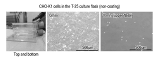
- FIG. 4 is a view showing a state of detachment of CHO-K1 cells according to the elapse of time.
- FIG. 9 is a view showing the measurement results of the cell detachment rate of CHO-K1 cells.
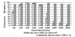
- FIG. 10 is a view showing the measurement results of the cell detachment rate and the survival rate of CHO-K1 cells according to the electric field intensity.
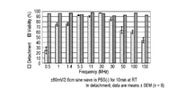
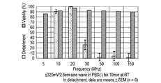
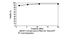
- FIG. 9 is a view showing the measurement results of the cell detachment rate and the survival rate of CHO-K1 cells according to the frequency. It is a figure which shows the comparison result of the growth curve after the cell passage by AC electric field and trypsin treatment. It is a figure which shows the mode of the peeling of the BALB / 3T3 cell according to time progress with respect to time. It is a figure which shows the measurement result of the cell detachment rate and the survival rate according to the electric field intensity about BALB / 3T3 cell. It is a figure which shows the measurement result of the cell detachment rate and the survival rate according to frequency about BALB / 3T3 cell.
- FIG. 4 is a diagram showing a state of detachment of cells over time by applying an alternating electric field from above and below to CHO-K1 cells in the stacked culture flasks.
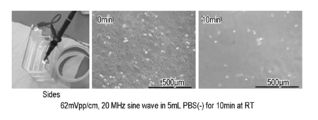
- FIG. 7 is a diagram showing a state of detachment of cells over time by application of an AC electric field from the side (lateral direction) to CHO-K1 cells in a stacked culture flask. It is a figure which shows the measurement result of the cell detachment rate and the survival rate under each condition. It is a figure which shows the mode of peeling of the cell according to time passage in the case of using PBS (+) containing calcium. It is a figure which shows the measurement result of the cell detachment rate and the survival rate under each condition.
- FIG. 3 is a diagram showing a state of detachment of CHO-K1 cells on a laminin-coated electrode over time with respect to time.
- FIG. 3 is a view showing a cell detachment rate of CHO-K1 cells on an electrode provided with a laminin coat.
- FIG. 4 is a view showing the survival rate of CHO-K1 cells on an electrode provided with a laminin coat.
- FIG. 3 is a view showing a state of detachment of CHO-K1 cells on a vitronectin-coated culture flask over time with time.
- FIG. 3 is a diagram showing a state of detachment of CHO-K1 cells on a laminin-coated electrode over time with respect to time.
- FIG. 3 is a view showing a cell detachment rate of CHO-K1 cells on an electrode provided with a laminin coat.
- FIG. 4 is a view showing the survival rate of CHO-K1 cells on an
- FIG. 2 is a view showing a state of detachment of CHO-K1 cells on a vitronectin-coated culture flask over time as the cells elapse. It is a figure which shows the measurement result of the cell detachment rate and the survival rate under each condition. It is a figure which shows the mode of cell detachment about iPS cell in case an alternating electric field is not applied. It is a figure which shows the mode of cell detachment about iPS cell at the time of applying an alternating electric field. It is a figure which shows the mode of the cell proliferation according to time progress about the control for a comparison. It is a figure which shows a mode of cell growth when an alternating electric field is applied.
- FIG. 3 is a diagram showing a state of cells grown on microcarrier beads. It is a figure showing the measurement result of the number of cells under various conditions. It is a figure which shows the measurement result of the survival rate under various conditions. It is a figure showing the example of composition of the cell stimulation device concerning one embodiment of the present invention. It is a figure which shows a mode of cell detachment with time progress. It is a figure which shows a mode of cell detachment with time progress. It is a figure which shows the result of a cell detachment rate and a survival rate.
- the cell stimulating device is configured as a device that stimulates cells to change the behavior and properties of the cells.
- an outline of the cell stimulator will be described.
- Type of cell Cells that can be stimulated by the cell stimulator are not limited, and can be applied to various cells, for example, cells of animals, insects, plants, and the like, microorganisms, bacteria, and the like.
- Animal-derived cells include humans, monkeys, dogs, cats, rabbits, rats, nude mice, mice, guinea pigs, pigs, sheep, Chinese hamsters, cows, marmosets, African green monkeys, and the like, but are not particularly limited. Absent.
- the present invention can be applied to various stem cells (iPS cells, ES cells, mesenchymal stem cells, adipose stem cells, and the like), cell lines, and tumor cells.
- Cell state The state of the cell to be stimulated by the cell stimulator is not particularly limited.
- the cell stimulator can be configured to stimulate cells in a state of being adhered to the culture substrate, for example.
- the culture substrate include a plate-shaped substrate, a spherical or granular substrate called a so-called microcarrier, and a cylindrical substrate called a roller bottle.
- the plate-shaped culture substrate may be a culture surface of a member generally used for culture purposes (a so-called culture flask, petri dish, or stack plate).
- a metal plate or a conductive member having an ITO electrode formed on a glass surface can be used as the plate-shaped culture substrate.
- the surface of the culture substrate may have been subjected to various treatments for culturing cells (etching treatment for adjusting surface roughness or coating treatment).
- the cell stimulating device is in a state isolated from the culture substrate, a state in which cells are aggregated to form an aggregate, a tissue state, a living body state, a seed state, germination. It is also possible to configure so as to stimulate cells in a later plant state.
- Cell stimulators stimulate cells in a state of being immersed in a solution (including a state in which cells are immersed in body fluid as a tissue or a living body, or a state in which cells are taken out of a living body and immersed in a solution). It is composed of
- the stimulus-imparting treatment may be performed in a state where the cells are held together with the solution in a container such as a culture flask or a petri dish.
- the type of solution is not particularly limited, but various types can be applied depending on the type of cell and the purpose of stimulation.
- a culture solution such as a serum medium may be used as the solution, or PBS (-) free from calcium and magnesium may be used.
- a liquid containing an additive depending on the purpose can be used.
- the purpose of stimulating cells with a cell stimulator is to change the behavior and properties of the cells, and various examples can be given. For example, detachment of cells from the culture substrate (including detachment in the form of a sheet and detachment while separating into single cells), morphological change, growth suppression, gene expression and protein production, culture products It can be used for various purposes, such as denaturation, change in production amount, differentiation induction and initialization.
- the cell stimulator can also be used for the purpose of treating living organisms (animals and plants including humans) and controlling growth by stimulating cells in the living body.
- the cell stimulating device is provided with an applying means capable of applying an AC electric field between two electrodes, and stimulating the cells by arranging the cells in the generated AC electric field (AC electric field) (AC electric field). Is applied).
- AC electric field AC electric field
- Examples of the waveform of the AC electric field include, but are not limited to, a sine wave, a rectangular wave, a triangular wave, and a sawtooth wave.
- a sine wave can be used.
- the cells are placed in an alternating electric field while immersed in the solution, and at least one of the two electrodes is configured to be out of contact with the cells and the solution.
- the two electrodes may be so-called parallel plate electrodes in which plate electrodes are arranged in parallel with each other.
- the arrangement of the electrodes is not particularly limited, and it is possible to arrange the cells and the solution so as to sandwich them from above and below, or to sandwich them from the side (lateral direction).
- the electrode can be configured to sandwich one container, or can be configured to sandwich a plurality of containers.
- the frequency of the AC electric field generated by the cell stimulator can be in a range where the dielectric loss of water is equal to or less than a predetermined value.
- a predetermined value For example, as shown in FIG. 1 showing the frequency characteristic of the dielectric loss ⁇ of water, it is known that an AC electric field having a frequency of 0.5 MHz to 1000 MHz reduces the dielectric loss ⁇ of water. Can be used.
- the intensity of the AC electric field (electric field intensity) generated by the cell stimulator can be determined according to the purpose of the cell stimulation. However, even when the AC electric field is about ⁇ 0.3 V / m, the cells are stimulated and behave. Was changed (details will be described later).
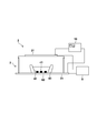
- the cell stimulating device 1 for stimulating cells includes a function generator 10.
- the function generator 10 functions as an application unit that can apply an AC electric field between the electrode 20 (first electrode) and the electrode 30 (second electrode).
- the function generator 10 applies an AC electric field to stimulate cells arranged between the electrode 20 and the electrode 30 facing the electrode 20.
- the cell stimulating device 1 includes a voltmeter 5 (oscilloscope). The voltage between the two electrodes 20 and 30 can be measured by the voltmeter 5. Then, an AC electric field (electric field) can be calculated based on the measured voltage and the distance between the two electrodes 20 and 30.
- the cell stimulator may be configured without a voltmeter. That is, the electric field of a desired intensity is applied between the electrodes by adjusting the set value of the function generator 10 by previously confirming the set value of the function generator 10 and the electric field intensity applied between the electrodes. It becomes possible.
- the function generator 10 is an electronic device that can generate an AC voltage signal having a desired frequency and waveform. By connecting the function generator 10 to the electrodes 20 and 30, an AC voltage is generated between the electrodes 20 and 30. An electric field can be generated.
- the type of the function generator 10 applicable to the present embodiment is not particularly limited, the function generator 10 having an output (frequency, voltage, waveform) according to a target cell or a purpose of stimulation is used. It is preferable to select and design.
- the types of the electrode 20 and the electrode 30 are not particularly limited.
- a transparent electrode indium oxide (ITO) / glass electrode
- a metal electrode such as stainless steel, copper, or aluminum
- the electrode 20 and the electrode 30 can be configured as, for example, plate electrodes.
- the flat electrodes are arranged in parallel and opposed to each other, an electric field can be generated uniformly (to prevent unevenness) between the electrodes.
- the plate electrode includes a form that can be regarded as a substantially flat plate, in addition to a so-called plate-like electrode.
- a flat plate electrode with a mesh structure one with an edge bent inward to avoid the divergence of the electric field at the peripheral edge, and a gently curved whole to make the electric field between the electrodes uniform And the like.
- the electrode 20 and the electrode 30 are arranged so as not to come into contact with cells to be stimulated and a solution for immersing the cells.
- the cells may be enclosed in a container together with the solution, and the container may be disposed between the electrode 20 and the electrode 30. That is, the electrode 20 and the electrode 30 can be arranged outside the container. According to this, since the electrodes do not come into contact with the cells and the solution, it is possible to prevent the physical properties of the electrodes 20 and 30 from affecting the cells.
- the container is preferably made of a material having a small effect on the electric field.
- the electric field generated between the electrode 20 and the electrode 30 is less likely to be affected by the container, so that the electric field can be uniformly applied to the cells.
- a resin container containing no metal or magnetic material is exemplified.
- the electrode 20 and the electrode 30 outside the container, it becomes possible to perform the cell stimulating treatment without opening and closing the container, and thus it is possible to reduce the risk of occurrence of contamination in the container. .
- the culture flask 40 is used as a container, and the function generator 10 applies an AC electric field with the culture flask 40 disposed between the two electrodes 20 and 30.
- the culture flask 40 contains cells 41 and a liquid 42, and the function generator 10 is used to stimulate the cells 41 between the two electrodes 20, 30.
- the inner surface (bottom inner wall surface) of the culture flask 40 is a culture substrate, and the cells 41 may be adhesive cells adhered to the inner surface of the culture flask 40. Alternatively, the cells 41 may be arranged in the culture flask 40 in a state of being adhered to a fine spherical or granular culture substrate called a microcarrier.
- the frequency of the AC electric field applied between the electrodes can be appropriately adjusted according to conditions such as the type of cells and the purpose of stimulation.
- the frequency of the alternating electric field is at least 0.1 MHz, preferably at least 0.5 MHz, more preferably at least 2 MHz, even more preferably at least 5 MHz, while at most 1000 MHz. , Preferably at most 200 MHz, more preferably at most 50 MHz, even more preferably at most 25 MHz.
- the frequency (band) of the AC electric field applied between the electrodes can be set based on the dielectric loss of water. That is, when an AC electric field is applied to water, it is known that at low frequencies, ions in the water move to cause dielectric loss, and the dielectric loss decreases as the frequency increases.
- an AC electric field AC electric field of approximately 0.5 MHz or more and 1000 MHz or less
- the movement of ions in the solution is minimized.
- the stimulus by the electric field can be directly applied to the cell, and the stimulating efficiency of the cell can be improved.
- the strength of the AC electric field (electric field strength) applied between the electrodes is not particularly limited, and can be appropriately set according to the type of cell and the purpose of stimulation.
- the intensity of the AC electric field can be, for example, not less than ⁇ 0.3 V / m.
- the intensity of the AC electric field is ⁇ 1 mV / 2.6 cm or more, more preferably ⁇ 5 mV / 2.6 cm or more, more preferably ⁇ 15 mV / 2.6 cm or more, and particularly preferably. It is ⁇ 50 mV / 2.6 cm or more, while it is ⁇ 10000 mV / 2.6 cm or less, preferably ⁇ 3000 mV / 2.6 cm or less, and more preferably ⁇ 2000 mV / 2.6 cm or less.
- the voltage may be increased or decreased in proportion.
- the specific values of the frequency of the AC electric field applied to the cells and the electric field strength are appropriately set according to the type of the cell and the purpose of the stimulation, and the optimum values can be derived experimentally.
- the strength of the AC electric field (electric field strength) and the time during which the AC electric field is applied, or the environment in which the cells are placed at that time are appropriately set according to the type of the cell and the purpose of applying the stimulus.
- the optimal value can be derived experimentally.
- the cell stimulating device 1 may be configured to include a measuring unit that measures a voltage between the electrode 20 and the electrode 30. At this time, the output of the function generator 10 may be adjusted based on the measurement value of the measurement unit. This makes it possible to apply an electric field (electric field) having a desired intensity between the electrode 20 and the electrode 30.
- a measuring unit that measures a voltage between the electrode 20 and the electrode 30.
- the container applicable to the present embodiment is not particularly limited.
- a culture flask is exemplified, but any known container such as a petri dish can be used.
- FIG. 2 only one container may be used, but the present invention is not limited to this. In other words, a plurality of containers may be stacked vertically and used, or may be used side by side.
- cells arranged between two electrodes can be stimulated only by applying an AC electric field between the two electrodes using a function generator, so that the cells can be stimulated with a simple configuration.
- a function generator so that the cells can be stimulated with a simple configuration.
- the cell stimulating method includes, as a preparation thereof, a step of preparing cells to be stimulated.
- the cells may be prepared by culturing, or a step of obtaining a cultured one and applying a stimulus may be performed.
- the cells may be in a state of being adhered to the culture substrate, but are not limited thereto. For example, those in an isolated state or those in which cells aggregate to form an aggregate can be applied.
- the cell may be a piece of tissue, a state of a living body, or a state separated from the living body.
- the cells are prepared in a state of being immersed in a liquid.
- the cells can be prepared in a state of being stored in a container together with a liquid.
- the liquid can be appropriately selected according to the purpose of stimulation.
- the liquid may be a culture solution used for the culture, or a liquid obtained by replacing the culture solution (a solution suitable for the cell stimulating step).
- the cell stimulating method includes a step of disposing a cell 41 and a liquid 42 for immersing the cell 41 between the electrode 20 and the electrode 30.
- this step can be realized by disposing the culture flask 40 between the electrode 20 and the electrode 30. This step is performed so that at least one of the electrode 20 and the electrode 30 is not in contact with the cell 41 and the liquid 42. In the example shown in FIG. 2, in this step, both the electrode 20 and the electrode 30 are not in contact with the cell 41 and the liquid 42.
- the cell stimulating method includes a step of applying an alternating electric field between the electrode 20 and the electrode 30.
- the AC electric field (frequency, waveform, intensity, time) applied in this step can be appropriately set according to the purpose of stimulation.
- the environment temperature, humidity, illuminance, lightness
- the cells during this step can also be appropriately set according to the purpose of stimulation.
- ⁇ Cells can be stimulated by the above steps, and various products can be produced.
- the cell stimulating method when used for the purpose of detaching (isolating) cells from a culture substrate, the isolated cells detached (isolated) from the culture substrate can be used as a product.
- the present invention is also applicable to a cell growth method in which isolated cells detached from a culture substrate by cell stimulation are cultured and grown.
- the cell stimulating method when used to change the physical properties of a metabolite of a cell or to adjust the production amount, the metabolite of the cell can be used as the product.
- the stimulating method when the stimulating method is used for cell denaturation (gene expression, differentiation induction, reprogramming, etc.), the denatured cells can be used as a product.
- peeling of cells on a culture substrate will be described as an example of stimulation to cells.
- the detachment rate which is the percentage of detached cells, is calculated by randomly measuring cell densities at six locations on a 500 ⁇ m ⁇ 500 ⁇ m culture substrate before and after the detachment treatment. When the peeling ratio exceeds 95%, it is assumed that the film has been completely peeled.
- the survival rate which is the rate at which the detached cells survive, is calculated by using a viability determination method by trypan blue staining.
- the T-25 culture flask 40 has a thickness of about 2.6 cm and a capacity of about 50 ml, and the space above the PBS ( ⁇ ) in the flask is filled with air.
- the upper and lower sides of the T-25 culture flask 40 were sandwiched between two electrodes 20 and 30, and an AC electric field of ⁇ 80 mV / 2.6 cm and 20 MHz was applied between both electrodes at room temperature. After applying an AC electric field for 10 minutes, pipetting was performed 7 to 10 times with 5 mL of PBS ( ⁇ ) in a T-25 culture flask 40 to confirm the presence or absence of cell detachment.
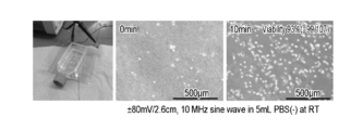
- FIG. 3A shows that the CHO-K1 cells in PBS ( ⁇ ) were stimulated for 0 minute, 5 minutes, and 10 minutes by applying an AC electric field of ⁇ 80 mV / 2.6 cm and 20 MHz. The appearance of CHO-K1 cells in each case is shown.
- FIG. 3B shows the detachment rate of CHO-K1 cells. The results on the leftmost side of FIG. 3B are the results obtained when 0 mV and 10 minutes, that is, the CHO-K1 cells were allowed to stand in PBS ( ⁇ ) at room temperature for 10 minutes without applying an AC electric field. CHO-K1 cells did not detach from the culture substrate surface.
- the second from the left shows the results when an AC electric field of ⁇ 80 mV / 2.6 cm, 20 MHz was applied for 3 minutes, and in this case also, CHO-K1 cells hardly detached from the culture substrate surface.
- the third from the left shows the results when an AC electric field of ⁇ 80 mV / 2.6 cm, 20 MHz was applied for 5 minutes, and the peeling rate was less than 10%.
- the rightmost result is obtained when an AC electric field of ⁇ 80 mV / 2.6 cm, 20 MHz was applied for 10 minutes, and the peeling rate was more than 95%. That is, it was completely peeled.
- FIG. 4A shows the cell detachment rate and the detached cells of CHO-K1 cells in PBS ( ⁇ ) when an AC electric field of 20 MHz and ⁇ 10 to ⁇ 6500 mV / 2.6 cm is applied for 10 minutes each. It is a measurement result of the survival rate of the.
- the bar graph on the left side shows the cell detachment rate and the bar graph on the right side shows the survival rate for each application condition.
- FIG. 4B shows the cell detachment rate and the detached cells of the CHO-K1 cells in PBS ( ⁇ ) when an AC electric field of ⁇ 80 mV / 2.6 cm and 0.5 to 150 MHz was applied for 10 minutes each. It is a measurement result of the survival rate of the.
- the bar graph on the left side shows the cell detachment rate and the bar graph on the right side shows the survival rate for each application condition.
- the cells were stimulated to change their behavior by applying an AC electric field having a frequency of 0.5 MHz or more.
- cells were exfoliated by applying an AC electric field of 0.5 to 150 MHz, and that the cell exfoliation rate was increased by applying an AC electric field of 1 to 100 MHz.
- FIG. 4A and FIG. 4B show that at 20 MHz and an alternating electric field of ⁇ 10 to ⁇ 6500 mV / 2.6 cm, and at an alternating electric field of ⁇ 80 mV / 2.6 cm and 0.5 to 150 MHz, more than 90% Survival.
- the CHO-K1 cells were exfoliated by applying an alternating electric field of ⁇ 80 mV / 2.6 cm, 20 MHz at room temperature for 10 minutes from above and below the T-25 culture flask 40 in which PBS (-) was replaced. did.
- the plate is treated with 1 ⁇ Trypsin EDTA (a 10 ⁇ Trypsin EDTA solution diluted 10 times with PBS ( ⁇ )) at 37 ° C. for 10 minutes to obtain a T-25 culture flask 40 From the CHO-K1 cells.
- the detached cells were seeded at a cell density of 1 ⁇ 10 5 cells / T-25 cultureflash. Then, the cell density was measured by setting the time 3 hours after the cell seeding to 0 hour.
- Animal cell growth generally includes four periods: a lag phase (or lag phase: Lag @ phase, lag time), a logarithmic growth phase (Log @ phase), a stationary phase (Stationary @ phase), and a death phase (Death @ phase). 3 shows a growth curve.
- the lag phase is the period during which cells do not divide and are trying to adapt to a new environment. The length of the lag phase depends on the cell density and the time of injury recovery upon seeding.
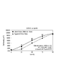
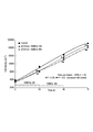
- FIG. 5 is a diagram showing a comparison result of a growth curve after cell passage by application of an AC electric field and trypsin treatment at the time of the above investigation.
- the growth curve of the CHO-K1 cells by the alternating electric field is different from the growth curve in the case of performing trypsin treatment, in that there is almost no induction period in which cell division does not occur, and the cell immediately enters the logarithmic growth period. Became clear. That is, as shown in FIG. 5, it was found that the cells detached by the application of an AC electric field subsequently proliferated, and the lag time (induction period) of the proliferation became shorter than in the case where trypsin treatment was performed. In particular, it can be seen that the increase in cell density is greater when an AC electric field is applied between 0 and 24 hours than when trypsin treatment is performed.
- FIG. 6A shows the state of BALB / 3T3 cells when a ⁇ 320 mV / 2.6 cm, 20 MHz AC electric field is applied for 10 minutes to stimulate BALB / 3T3 cells in PBS ( ⁇ ). The cells were completely detached by applying an AC electric field for 10 minutes.
- FIG. 6B shows the cell detachment rate and the survival rate of detached cells of BALB / 3T3 cells in PBS ( ⁇ ) when an AC electric field of 20 MHz and ⁇ 80 to ⁇ 6500 mV / 2.6 cm is applied for 10 minutes each. Is the measurement result. 6B and 6C, the bar graph on the left side shows the cell detachment rate and the bar graph on the right side shows the survival rate for each application condition.
- FIG. 6C shows cell detachment rate and survival of detached cells when an AC electric field of ⁇ 320 mV / 2.6 cm and a range of 0.5 to 150 MHz was applied for 10 minutes for BALB / 3T3 cells in PBS ( ⁇ ). It is a measurement result of a rate.
- a plurality of T-25 culture flasks 40 in which CHO-K1 cells are cultured are prepared as the cells 41, and the AC electric field is vertically increased or decreased in a state where they are vertically stacked. Apply laterally.
- a plurality of containers (for example, a T-25 culture flask) can be processed at a time with the same apparatus configuration as in FIG. 2, so that processing efficiency can be improved.
- a plurality of containers may be arranged in the left-right direction.
- the distance between the electrodes is increased, but a desired electric field intensity can be maintained by adjusting the voltage according to the distance.
- the results obtained by disposing the electrodes 20 and 30 on the side surface of the T-25 culture flask 40 and applying an AC electric field from the lateral direction were almost the same. That is, the CHO-K1 cells were completely detached at a survival rate of 96% under any of the application conditions.
- cell detachment can be performed without depending on the direction of application of the AC electric field, and smooth cell detachment can be realized even when a plurality of T-25 culture flasks 40 exist.
- Example 3 As in Example 1, cells 41 (CHO-K1 cells) were cultured in a T-25 culture flask 40 in advance to 80% or more subconfluence.
- condition 2 the presence or absence of cell detachment was confirmed under the same conditions as in Condition 1 except that after washing, replacement with fresh 1 ml of liquid 42 (PBS (-)) was performed (condition 2).
- condition 3 the presence or absence of cell detachment was confirmed under the same conditions as in Condition 1 except that the liquid 42 (PBS (-)) was removed (0 ml) after washing (condition 3).
- condition 4 the presence or absence of cell detachment was confirmed under the same conditions as in Condition 1 except that no AC electric field was applied.
- Condition 1 For comparison, the presence or absence of cell detachment was confirmed under the same conditions as in Condition 1 except that the cells were washed with PBS containing calcium (+), and after washing, replaced with fresh 5 ml of PBS (+). (Condition 5). For comparison, the presence or absence of cell detachment was confirmed under the same conditions as in Condition 1 except that the medium (1 ml) after culturing was not used and washed as it was (condition 6).
- FIG. 8A shows that CHO-K1 cells in PBS (+) containing calcium were stimulated at room temperature (Room @ Temperature) by applying an alternating electric field of ⁇ 80 mV / 2.6 cm, 20 MHz for 0 minute and 10 minutes. Shows the state of CHO-K1 cells in each case. The cells did not detach after 10 minutes.
- FIG. 8B shows the measurement results of the cell detachment rate and the survival rate under each application condition. N. in the survival rate in the figure. D indicates that no data was measured.
- FIG. 8A corresponds to the third example from the left in FIG. 8B.
- the cell stimulating device 2 includes a function generator 10, and the function generator 10 applies an AC electric field to the cells 41 (CHO-K1 cells) of the culture dish 3 formed by the two electrodes 21 and 31. Functions as a means.
- the electrode 21 is, for example, an ITO / PET film electrode
- the electrode 31 is, for example, an ITO / glass electrode.
- an electrode 21 (ITO / PET film electrode) was placed on the top, and an electrode 31 (ITO / glass electrode) was placed on the bottom, and a culture dish 3 capable of applying an AC electric field was prepared.
- a flexiPERM 50 is attached on the electrode 31 (ITO / glass electrode), and a laminin coat 60 of 5 ⁇ g / cm 2 is applied.
- Cells 41 (CHO-K1 cells) were cultured on laminin-coated electrodes 31 (ITO / glass electrodes) to a subconfluence of 80% or more. Then, the medium was replaced with 5 ml of liquid 42 (PBS (-)), and an AC electric field of ⁇ 80 mV / 1.1 cm and various frequency conditions was applied at room temperature for 10 minutes.
- FIG. 10A shows the state of each CHO-K1 cell when the CHO-K1 cell was stimulated for 0 minute and 10 minutes under the above conditions.
- FIG. 10B shows the measurement results of the cell detachment rate under the above conditions, and
- FIG. 10C shows the measurement results of the survival rate under the above conditions.
- FIG. 10B the CHO-K1 cells were completely detached under the conditions of 1.4 MHz, 5.5 MHz, 11 MHz and 20 MHz.
- FIG. 10A corresponds to the result under the application condition of 20 MHz in FIG. 10B, and it can be observed that the cells are detached.
- the CHO-K1 cells obtained a survival rate of more than 90% in an alternating current electric field of 5.5 MHz, 11 MHz and 20 MHz.
- FIG. 11A is a result by applying an AC electric field of ⁇ 80 mV / 2.6 cm and 20 MHz (room temperature for 10 minutes)
- FIG. 11B is a result by applying an AC electric field of ⁇ 80 mV / 2.6 cm and 10 MHz (room temperature for 10 minutes). The result.
- FIG. 11C shows the measurement results of the cell detachment rate and the survival rate when an AC electric field of ⁇ 80 mV / 2.6 cm was applied for 10 minutes at room temperature.
- the peeling rate is less than 50%.
- the peeling rates when the coating material is not used, the peeling rates when the electric fields of 5.5 MHz and 11 MHz, which are relatively close to 10 MHz, are applied. It is about 90%.
- Example 6 ⁇ Experiment contents and results>
- Cells 41 iPS cells (strain 771-2, passage number 6) were cultured in a T-25 culture flask 40 coated with 0.5 ⁇ g / cm 2 of laminin 511E8. After washing the iPS cells with liquid 42 (PBS (-)), 5 mL of 0.5 ⁇ TrypLEselect was added. The iPS cells were placed in a 5% CO2 incubator, treated with TrypLEselect at 37 ° C. for 4 minutes, and then pipetted 10 times with TrypLeselect.
- FIG. 12A shows the results. Even after pipetting, the colonies of iPS cells hardly detached from the culture substrate surface.
- an AC electric field of ⁇ 320 mV / 2.6 cm and 20 MHz was applied to the similarly prepared iPS cells at the time of TrypLeselect treatment for 4 minutes.
- tapping which is a peeling method weaker than pipetting, was performed 20 times from the side of the T-25 culture flask 40.
- FIG. 12B shows the results, in which colonies of iPS cells were completely or partially detached.
- the survival rate of the detached iPS cells was 97%. As described above, it was confirmed that the application of the AC electric field stimulated the iPS cells, and facilitated the iPS cell separation.
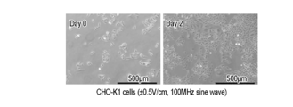
- the growth rate is affected when culturing while applying an AC electric field of ⁇ 0.5 V / cm and 100 MHz to CHO-K1 cells in Ham's F-12 medium for 2 days. Checked whether or not. As a result, it was found that the cells were stimulated to suppress the growth rate.
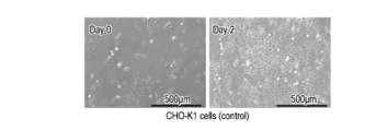
- FIG. 13A is a diagram showing a state of proliferation of CHO-K1 cells in Control for comparison.
- FIG. 13B is a view showing a state of proliferation of the CHO-K1 cells when an AC electric field of ⁇ 0.5 V / cm and 100 MHz is applied to the CHO-K1 cells.
- FIG. 13C shows the measurement results of the cell density under each condition of FIGS. 13A and 13B.
- 0, 24, and 48 on the horizontal axis represent the time from the start of proliferation, respectively, and the numerical value on the vertical axis represents the cell density.
- the three on the left correspond to FIG. 13A and show the results under control.
- the three on the right correspond to FIG. 13B and show the results when a ⁇ 0.5 V / cm, 100 MHz AC electric field is applied.
- the cell stimulating device according to the present embodiment functions as a cell growth suppressing device.
- FIG. 14 is a diagram showing a change in the value of cell density (number / cm 2) over time (state of proliferation). The three results are shown in the case where no AC electric field of ⁇ 0.5 V / cm and 100 MHz is applied (control), when the application is stopped after applying for 24 hours, and when the application is stopped after applying for 48 hours. Have been.
- the cell density was 66% as compared to the control for the control, and the proliferation was suppressed. That is, it can be seen that the cell density increases with a gentler gradient than the control.
- Embodiment 8 As an example of stimulating cells, an AC electric field is applied by a function generator to CHO-K1 cells cultured on microcarrier beads. As a result, it was found that the cells cultured on the microcarrier beads were stimulated by the application of an AC electric field, and the cells were detached. Note that the device configuration is the same as that of FIG. In addition, as the microcarrier beads, polystyrene beads manufactured by Corning Incorporated are used, but not limited to the beads, other microcarrier beads may be used.
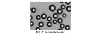
- FIG. 15A shows an example of CHO-K1 cells cultured on microcarrier beads. It can be observed that CHO-K1 cells are cultured on a plurality of microcarrier beads.
- FIG. 15B shows the measurement results of the number of detached cells under various conditions.
- the graph marked with vertical @ swing is the result when the AC electric field and the vertical vibration are applied simultaneously, and the graph marked with vortex shows that the vibration is applied after the application of the AC electric field.
- the result is shown (the same applies to FIG. 15C described later).
- the vertical vibration processing (vertical swing) is vertical swing at 2500 rpm.
- FIG. 15B the leftmost result is obtained when trypsin EDTA treatment was performed for 10 minutes.
- the second from the left shows the results when vertical vibration processing (vertical swing) was performed by adding a solution to which only EDTA was added and applying an AC electric field of ⁇ 320 mV / 2.6 cm, 20 MHz for 10 minutes.
- the third from the left shows the results when vortexing was performed for 1 minute 10 minutes after the application of a solution containing only EDTA and the application of an AC electric field of ⁇ 320 mV / 2.6 cm and 20 MHz.
- the fourth from the left shows the result when the EDTA treatment was performed for 10 minutes.
- the third from the right in FIG. 15B is the result when vertical vibration processing (vertical swing) is performed while adding an EDTA-free solution and applying an AC electric field of ⁇ 320 mV / 2.6 cm and 20 MHz for 10 minutes. is there.
- the second from the right shows the result when vortexing was performed for 1 minute 10 minutes after applying an AC electric field of ⁇ 320 mV / 2.6 cm and 20 MHz by adding a solution containing no EDTA. From these graphs and the fourth graph from the left, it can be seen that by applying an AC electric field, the same degree of cell detachment as EDTA treatment can be realized without using EDTA.
- the rightmost graph shows the result when a solution containing no EDTA was added and vortexed for 1 minute without applying an AC electric field. Thus, it was confirmed that more cells were detached when the AC electric field was applied. That is, it was also found that the cells cultured on the microcarrier beads were stimulated by the application of an AC electric field to change their behavior (promote detachment).
- FIG. 15C shows the results of measuring the survival rate of detached cells under various conditions.
- trypsin EDTA treatment was performed, the survival rate was 99% (leftmost in FIG. 15C).
- a vertical ⁇ swing process was performed while applying an AC electric field of ⁇ 320 mV / 2.6 cm and 20 MHz, the survival rate was 95% (third from the right in FIG. 15C).
- the configuration in which the electrode is included in the cell stimulating device has been described, but the electrode may not be included in the cell stimulating device.
- the upper and lower portions of the T-25 culture flask 40 and the like may be formed of an electrode plate and connected to the function generator 10.
- a stainless steel shield (enclosure) may be provided around the cell stimulator in which the cells are arranged according to the strength of the AC electric field to reduce the influence on the periphery of the device.
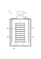
- the cell stimulator 4 is configured as a device that stimulates cells by arranging the cells in an alternating electric field generated between the electrodes 20 and 30.
- the electrode 20 and the electrode 30 are connected to the amplifier 12.
- the amplifier 12 receives the electric signal of the function generator 10, amplifies the intensity, and applies the amplified signal to the electrode. By using the amplifier 12, the electric field intensity generated between the electrode 20 and the electrode 30 can be easily adjusted.
- the electrode 20 and the electrode 30 are arranged in the shield 14.
- the shield 14 has a role of confining the electromagnetic wave generated inside and not leaking it to the outside. According to this, even when the output of the amplifier 12 is increased, it is possible to prevent electromagnetic waves (radio waves) generated between the electrodes 20 and 30 from affecting surroundings.
- the cell stimulator 4 has a support 16.
- the support 16 serves to support the container.
- the support 16 is disposed inside the shield 14.
- the support 16 is preferably made of a material that does not affect the AC electric field generated by the electrodes 20 and 30.
- the support 16 can be made of, for example, a resin material containing no metal or magnetic material.
- the support 16 is configured to be able to shake the container.
- the support 16 may be configured to make a reciprocating motion or a turning motion in the horizontal direction.
- the support 16 may be configured to move vertically. That is, the support 16 is connected to an actuator (not shown) and can be configured to perform a desired movement.
- the support 16 may be configured to be able to shake the container while applying an AC electric field to the electrodes 20 and 30. Alternatively, the support 16 may be configured to be able to shake the container after applying an AC electric field to the electrodes 20 and 30.
- the container that can be used in the cell stimulating device 4 is not particularly limited. As shown in FIG. 16, a container in which a plurality of containers are stacked in multiple stages (a so-called stack plate 60) is used. It is possible to use. According to this, a large amount of cells can be processed at one time.
- the electrode 20 and the electrode 30 are arranged on the side of the container, and are configured to apply an AC electric field from the side of the container. With such a configuration, an AC electric field can be applied to the cells, and the same effect as the cell stimulator 1 can be exhibited.
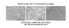
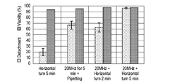
- condition b the state of cell detachment when the AC electric field was applied without performing the horizontal turning process
- condition c the condition of cell detachment under
- FIG. 17A is a diagram showing a state of cell detachment with time in condition a. The state at 0 minutes, 2 minutes, and 5 minutes from the left is shown. As a result, the cell detachment rate was 63% in 2 minutes and 97% in 5 minutes, as shown in the second and rightmost columns from FIG. 17C. The cell viability was 98% at 2 minutes and 5 minutes.
- FIG. 17B is a diagram showing a state of cell detachment with time under condition c. The state at 0 minutes and 5 minutes from the left is shown. The rightmost part of FIG. 17B shows a state where the T-25 culture flask 40 sandwiched between the electrodes 20 and 30 is placed on a swivel device that performs horizontal swivel. As a result, as shown in the leftmost part of FIG. 17C, the cell detachment rate was 20% in 5 minutes, and the cell survival rate was 94% in 5 minutes.
- the second from the left in FIG. 17C corresponds to the condition b.
- the cell detachment rate was about 67% in 5 minutes, and the cell survival rate was 95% in 5 minutes.
- cells can be easily stimulated with a simple configuration.
Landscapes
- Health & Medical Sciences (AREA)
- Life Sciences & Earth Sciences (AREA)
- Engineering & Computer Science (AREA)
- Chemical & Material Sciences (AREA)
- Bioinformatics & Cheminformatics (AREA)
- Organic Chemistry (AREA)
- Wood Science & Technology (AREA)
- Zoology (AREA)
- Genetics & Genomics (AREA)
- Biotechnology (AREA)
- Biomedical Technology (AREA)
- General Engineering & Computer Science (AREA)
- General Health & Medical Sciences (AREA)
- Microbiology (AREA)
- Biochemistry (AREA)
- Sustainable Development (AREA)
- Cell Biology (AREA)
- Physics & Mathematics (AREA)
- Electromagnetism (AREA)
- Molecular Biology (AREA)
- Medicinal Chemistry (AREA)
- Analytical Chemistry (AREA)
- Virology (AREA)
- Apparatus Associated With Microorganisms And Enzymes (AREA)
- Micro-Organisms Or Cultivation Processes Thereof (AREA)
- Immobilizing And Processing Of Enzymes And Microorganisms (AREA)
Abstract
L'invention concerne un dispositif de stimulation de cellules qui sépare des cellules adhérentes qui ont adhéré à un substrat de culture, du substrat de culture par stimulation des cellules. Le dispositif de stimulation de cellules comprend un moyen d'application susceptible d'appliquer un champ électrique alternatif entre une première électrode et une seconde électrode qui se font face et entre lesquelles sont interposées les cellules et une solution pour une immersion cellulaire. Au moins la première électrode ou la seconde électrode n'est pas en contact avec les cellules ou la solution.
Priority Applications (3)
| Application Number | Priority Date | Filing Date | Title |
|---|---|---|---|
| CN201980048529.1A CN112469811A (zh) | 2018-07-25 | 2019-06-12 | 细胞刺激装置、细胞刺激方法、培养产物的制造方法、分离细胞的制造方法和细胞增殖方法 |
| EP19840469.1A EP3812451A4 (fr) | 2018-07-25 | 2019-06-12 | Dispositif de stimulation de cellules, procédé de stimulation de cellules, procédé de production pour un produit de culture, procédé de production pour des cellules isolées, et procédé de prolifération cellulaire |
| US17/155,863 US20210139838A1 (en) | 2018-07-25 | 2021-01-22 | Cell stimulating apparatus, cell stimulating method, culture product manufacturing method, isolated cell manufacturing method, and cell growing method |
Applications Claiming Priority (2)
| Application Number | Priority Date | Filing Date | Title |
|---|---|---|---|
| JP2018139593 | 2018-07-25 | ||
| JP2018-139593 | 2018-07-25 |
Related Child Applications (1)
| Application Number | Title | Priority Date | Filing Date |
|---|---|---|---|
| US17/155,863 Continuation US20210139838A1 (en) | 2018-07-25 | 2021-01-22 | Cell stimulating apparatus, cell stimulating method, culture product manufacturing method, isolated cell manufacturing method, and cell growing method |
Publications (1)
| Publication Number | Publication Date |
|---|---|
| WO2020021896A1 true WO2020021896A1 (fr) | 2020-01-30 |
Family
ID=69181017
Family Applications (2)
| Application Number | Title | Priority Date | Filing Date |
|---|---|---|---|
| PCT/JP2019/023345 Ceased WO2020021896A1 (fr) | 2018-07-25 | 2019-06-12 | Dispositif de stimulation de cellules, procédé de stimulation de cellules, procédé de production pour un produit de culture, procédé de production pour des cellules isolées, et procédé de prolifération cellulaire |
| PCT/JP2019/029027 Ceased WO2020022382A1 (fr) | 2018-07-25 | 2019-07-24 | Procédé de stimulation cellulaire et dispositif de stimulation cellulaire |
Family Applications After (1)
| Application Number | Title | Priority Date | Filing Date |
|---|---|---|---|
| PCT/JP2019/029027 Ceased WO2020022382A1 (fr) | 2018-07-25 | 2019-07-24 | Procédé de stimulation cellulaire et dispositif de stimulation cellulaire |
Country Status (5)
| Country | Link |
|---|---|
| US (1) | US20210139838A1 (fr) |
| EP (1) | EP3812451A4 (fr) |
| JP (2) | JPWO2020022382A1 (fr) |
| CN (1) | CN112469811A (fr) |
| WO (2) | WO2020021896A1 (fr) |
Cited By (1)
| Publication number | Priority date | Publication date | Assignee | Title |
|---|---|---|---|---|
| JP2020103261A (ja) * | 2018-12-27 | 2020-07-09 | エイブル株式会社 | 細胞刺激装置 |
Families Citing this family (3)
| Publication number | Priority date | Publication date | Assignee | Title |
|---|---|---|---|---|
| JP2021153564A (ja) * | 2020-03-27 | 2021-10-07 | エイブル株式会社 | 細胞刺激装置及び電極ユニット |
| CZ310011B6 (cs) * | 2021-11-07 | 2024-05-08 | České vysoké učení technické v Praze | Laboratorní instrumentárium pro fyzikální stimulaci produkce kondiciovaného média mezenchymálních stromálních buněk |
| CN116855378A (zh) * | 2023-06-20 | 2023-10-10 | 浙江大学 | 一种恒定电场照射装置及其应用 |
Citations (7)
| Publication number | Priority date | Publication date | Assignee | Title |
|---|---|---|---|---|
| JPS5515094B2 (fr) | 1973-10-16 | 1980-04-21 | ||
| JPH05137576A (ja) * | 1991-11-15 | 1993-06-01 | Mayekawa Mfg Co Ltd | 細胞融合方法および細胞融合装置 |
| JP2004000046A (ja) * | 2002-05-31 | 2004-01-08 | Osaka Gas Co Ltd | 細胞が発信する音波の周波数測定方法 |
| JP2009065967A (ja) * | 2007-08-20 | 2009-04-02 | Gunma Univ | 細胞分離装置および細胞分離方法 |
| WO2011052717A1 (fr) * | 2009-10-30 | 2011-05-05 | 独立行政法人海洋研究開発機構 | Procédé de préparation de cellules animales proliférantes |
| WO2017075295A1 (fr) * | 2015-10-27 | 2017-05-04 | Berkeley Lights, Inc. | Appareil microfluidique comprenant un dispositif d'électromouillage ayant une surface hydrophobe liée par covalence |
| JP2018139593A (ja) | 2018-04-20 | 2018-09-13 | 公益財団法人ヒューマンサイエンス振興財団 | カンゾウ属植物の苗の生産方法 |
Family Cites Families (9)
| Publication number | Priority date | Publication date | Assignee | Title |
|---|---|---|---|---|
| US4487834A (en) * | 1982-09-17 | 1984-12-11 | Biolectron, Inc. | Electrical stimulation of articular chondrocytes |
| US5478303A (en) * | 1992-09-18 | 1995-12-26 | Foley-Nolan; Darragh | Electromagnetic apparatus for use in therapy |
| US6378527B1 (en) * | 1998-04-08 | 2002-04-30 | Chondros, Inc. | Cell-culture and polymer constructs |
| JP2000093170A (ja) * | 1998-09-25 | 2000-04-04 | Morinaga Milk Ind Co Ltd | 微生物の増殖抑制方法及び装置、並びに被処理物の保存方法 |
| JP5559460B2 (ja) * | 2004-12-27 | 2014-07-23 | スタンデン・リミテッド | 異なる配向の電界を用いて腫瘍またはその類似物を処理する方法 |
| CA2624624C (fr) * | 2005-10-03 | 2016-07-19 | Novocure Limited | Optimisation des caracteristiques d'un champ electrique pour augmenter l'effet du champ sur des cellules proliferantes |
| JP2011188834A (ja) * | 2010-03-16 | 2011-09-29 | Kawasaki Heavy Ind Ltd | 細胞カップリングモジュール、細胞カップリング装置及び細胞カップリング方法 |
| JP5920767B2 (ja) * | 2011-12-08 | 2016-05-18 | 石川県公立大学法人 | 通電処理による発酵温度の制御並びに食品微生物の増殖・代謝の促進方法 |
| US20180021563A1 (en) * | 2015-03-09 | 2018-01-25 | Koninklijke Philips N.V. | Iontophoretic device, arrangement and method |
-
2019
- 2019-06-12 EP EP19840469.1A patent/EP3812451A4/fr not_active Withdrawn
- 2019-06-12 WO PCT/JP2019/023345 patent/WO2020021896A1/fr not_active Ceased
- 2019-06-12 CN CN201980048529.1A patent/CN112469811A/zh active Pending
- 2019-07-24 JP JP2020532442A patent/JPWO2020022382A1/ja active Pending
- 2019-07-24 WO PCT/JP2019/029027 patent/WO2020022382A1/fr not_active Ceased
- 2019-07-25 JP JP2019137058A patent/JP6707773B2/ja active Active
-
2021
- 2021-01-22 US US17/155,863 patent/US20210139838A1/en not_active Abandoned
Patent Citations (7)
| Publication number | Priority date | Publication date | Assignee | Title |
|---|---|---|---|---|
| JPS5515094B2 (fr) | 1973-10-16 | 1980-04-21 | ||
| JPH05137576A (ja) * | 1991-11-15 | 1993-06-01 | Mayekawa Mfg Co Ltd | 細胞融合方法および細胞融合装置 |
| JP2004000046A (ja) * | 2002-05-31 | 2004-01-08 | Osaka Gas Co Ltd | 細胞が発信する音波の周波数測定方法 |
| JP2009065967A (ja) * | 2007-08-20 | 2009-04-02 | Gunma Univ | 細胞分離装置および細胞分離方法 |
| WO2011052717A1 (fr) * | 2009-10-30 | 2011-05-05 | 独立行政法人海洋研究開発機構 | Procédé de préparation de cellules animales proliférantes |
| WO2017075295A1 (fr) * | 2015-10-27 | 2017-05-04 | Berkeley Lights, Inc. | Appareil microfluidique comprenant un dispositif d'électromouillage ayant une surface hydrophobe liée par covalence |
| JP2018139593A (ja) | 2018-04-20 | 2018-09-13 | 公益財団法人ヒューマンサイエンス振興財団 | カンゾウ属植物の苗の生産方法 |
Non-Patent Citations (1)
| Title |
|---|
| See also references of EP3812451A4 * |
Cited By (2)
| Publication number | Priority date | Publication date | Assignee | Title |
|---|---|---|---|---|
| JP2020103261A (ja) * | 2018-12-27 | 2020-07-09 | エイブル株式会社 | 細胞刺激装置 |
| JP7282301B2 (ja) | 2018-12-27 | 2023-05-29 | エイブル株式会社 | 細胞刺激装置 |
Also Published As
| Publication number | Publication date |
|---|---|
| JP2020022443A (ja) | 2020-02-13 |
| WO2020022382A1 (fr) | 2020-01-30 |
| EP3812451A4 (fr) | 2021-08-11 |
| JPWO2020022382A1 (ja) | 2021-08-02 |
| EP3812451A1 (fr) | 2021-04-28 |
| US20210139838A1 (en) | 2021-05-13 |
| JP6707773B2 (ja) | 2020-06-10 |
| CN112469811A (zh) | 2021-03-09 |
Similar Documents
| Publication | Publication Date | Title |
|---|---|---|
| JP6707773B2 (ja) | 細胞刺激装置、細胞刺激方法、培養生成物の製造方法、単離細胞の製造方法及び細胞増殖方法 | |
| Blumenthal et al. | Effects of low‐intensity AC and/or DC electromagnetic fields on cell attachment and induction of apoptosis | |
| Pehlivanova et al. | Multiple effects of electroporation on the adhesive behaviour of breast cancer cells and fibroblasts | |
| Tenuzzo et al. | Biological effects of 6 mT static magnetic fields: a comparative study in different cell types | |
| Putame et al. | Compact and tunable stretch bioreactor advancing tissue engineering implementation. Application to engineered cardiac constructs | |
| McFarlane et al. | Changes in neurite outgrowth but not in cell division induced by low EMF exposure: influence of field strength and culture conditions on responses in rat PC12 pheochromocytoma cells | |
| JPWO2004083412A1 (ja) | 細胞培養方法及び細胞シート | |
| KR20150039997A (ko) | 자성나노입자와 전자기장을 이용한 골 재생 촉진 방법 | |
| JP2004305137A (ja) | インキュベータおよび細胞培養方法 | |
| CN109628402A (zh) | 一种胃癌肿瘤原代类器官培养方法 | |
| CN104694474B (zh) | 一种细胞培养方法 | |
| US20130295669A1 (en) | Method for controlling binding of cells to a substrate | |
| Bongiovanni et al. | Protocol for isolating and culturing neonatal murine cardiomyocytes | |
| JP2019030260A (ja) | 細胞生産方法及び細胞生産装置 | |
| Hogan et al. | Conditioning of cardiovascular tissue using a noncontact magnetic stretch bioreactor with embedded magnetic nanoparticles | |
| JP2018161097A (ja) | 培養細胞供試体の作製方法 | |
| Di Nardo et al. | Engineering the stem cell niche and the differentiative micro-and macroenvironment: Technologies and tools for applying biochemical, physical and structural stimuli and their effects on stem cells | |
| Ventura et al. | The use of physical energy for tissue healing | |
| Mamman et al. | Influence of Electroporation on HT29 Cell Proliferation, Spreading and Adhesion Properties | |
| Jian et al. | The isolation of fibroblasts by volumetric regulation cycles | |
| CN102586172A (zh) | 利用合成的、确定的胶原模拟表面进行细胞培养的方法 | |
| Selvamuthukumaran | Effects of an Oscillating Magnetic Field on the Stability of Stored Grain Produce | |
| JPWO2005123906A1 (ja) | インスリン産生細胞のインスリンの産生量および/または分泌量を増加させる方法 | |
| EP2514819B1 (fr) | Procédé d'immobilisation de microorganismes vivants et procédé de préparation de microorganismes vivants | |
| JP2002085053A (ja) | 生体組織から細胞を剥離する方法および装置 |
Legal Events
| Date | Code | Title | Description |
|---|---|---|---|
| 121 | Ep: the epo has been informed by wipo that ep was designated in this application |
Ref document number: 19840469 Country of ref document: EP Kind code of ref document: A1 |
|
| NENP | Non-entry into the national phase |
Ref country code: DE |
|
| ENP | Entry into the national phase |
Ref document number: 2019840469 Country of ref document: EP Effective date: 20210120 |