WO2020022061A1 - Structure de garnissage - Google Patents
Structure de garnissage Download PDFInfo
- Publication number
- WO2020022061A1 WO2020022061A1 PCT/JP2019/027294 JP2019027294W WO2020022061A1 WO 2020022061 A1 WO2020022061 A1 WO 2020022061A1 JP 2019027294 W JP2019027294 W JP 2019027294W WO 2020022061 A1 WO2020022061 A1 WO 2020022061A1
- Authority
- WO
- WIPO (PCT)
- Prior art keywords
- lining
- lining plate
- plate
- adjacent
- receiving piece
- Prior art date
- Legal status (The legal status is an assumption and is not a legal conclusion. Google has not performed a legal analysis and makes no representation as to the accuracy of the status listed.)
- Ceased
Links
Images





Classifications
-
- E—FIXED CONSTRUCTIONS
- E04—BUILDING
- E04F—FINISHING WORK ON BUILDINGS, e.g. STAIRS, FLOORS
- E04F13/00—Coverings or linings, e.g. for walls or ceilings
- E04F13/07—Coverings or linings, e.g. for walls or ceilings composed of covering or lining elements; Sub-structures therefor; Fastening means therefor
- E04F13/08—Coverings or linings, e.g. for walls or ceilings composed of covering or lining elements; Sub-structures therefor; Fastening means therefor composed of a plurality of similar covering or lining elements
- E04F13/12—Coverings or linings, e.g. for walls or ceilings composed of covering or lining elements; Sub-structures therefor; Fastening means therefor composed of a plurality of similar covering or lining elements of metal or with an outer layer of metal or enameled metal
-
- B—PERFORMING OPERATIONS; TRANSPORTING
- B23—MACHINE TOOLS; METAL-WORKING NOT OTHERWISE PROVIDED FOR
- B23K—SOLDERING OR UNSOLDERING; WELDING; CLADDING OR PLATING BY SOLDERING OR WELDING; CUTTING BY APPLYING HEAT LOCALLY, e.g. FLAME CUTTING; WORKING BY LASER BEAM
- B23K9/00—Arc welding or cutting
Definitions
- the present invention relates to a lining structure for shielding the surface of a concrete structure, a steel structure, a wooden structure or the like from the environment.
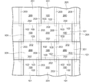
- the lining structure described in Patent Literature 1 includes a plurality of two types of lining plates, a first lining plate 100 and a second lining plate 200, which are alternately arranged in the vertical and horizontal directions.
- both the first lining plate 100 and the second lining plate 200 are formed on a pair of sides of the plate bodies 101 and 201 having a rectangular shape in plan view via a step.
- the main body includes the pieces 102 and 202 and cover pieces 203 and 203 formed on the other pair of sides of the plate bodies 101 and 201.
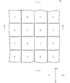
- FIG. 11 the lining structure described in Patent Literature 1 includes a plurality of two types of lining plates, a first lining plate 100 and a second lining plate 200, which are alternately arranged in the vertical and horizontal directions.
- both the first lining plate 100 and the second lining plate 200 are formed on a pair of sides of the plate bodies 101 and 201 having a rectangular shape in plan view via a step.
- the main body includes the pieces 102 and 202 and cover pieces 203
- the first lining plate 100 and the second lining plate 200 have a cover piece 203 of the second lining plate 200 superimposed on a receiving piece 102 of the first lining plate 100, and
- the cover pieces 203 of the second lining plate 200 are abutted against the plate body 101 of the second lining plate 200 to be arranged in one direction (horizontal direction in FIG. 11), and the first lining is placed on the receiving piece 202 of the second lining plate 200.
- the cover pieces 103 of the plate 100 are overlapped, and the cover pieces 103 of the first lining plate 100 are abutted against the plate body 201 of the second lining plate 200, so that they are arranged in the other direction (vertical direction in FIG. 11). Have been.
- the first and second lining plates 100 and 200 which are arranged in a row in the vertical direction, contact each other so that the receiving pieces 102 and 202 are in contact with each other so as not to be displaced in the horizontal direction. They are arranged in a regulated state. Therefore, the first and second lining plates 100 and 200, which are arranged in a row in the vertical direction, are prevented from inadvertently opening abutting portions between the lining plates adjacent in the horizontal direction due to a positional shift in the horizontal direction. Have been.
- the first and second lining plates 100 and 200 which are arranged in a row in the vertical direction are prevented from being displaced in the horizontal direction by the receiving pieces 102 and 202.
- the first and second lining plates 100 and 200 In rows adjacent to each other in the direction, the first and second lining plates 100 and 200 have a structure in which positional displacement in the horizontal direction is not prevented by the receiving pieces 102 and 202. Therefore, when combining a plurality of lining plates, there is a possibility that the rows may be displaced from each other in a lateral direction due to the action of an external force, and the rows may be separated from each other, so that there is room for improvement in workability when constructing the lining structure. There is.
- the present invention has been made in view of such circumstances, and has as its object to provide a lining structure with improved workability during construction.
- the lining structure of the present invention includes a plurality of first lining plates and a plurality of second lining plates, and the first lining plate and the second lining plate are arranged alternately in the vertical and horizontal directions on the lining surface.
- the first lining plate and the second lining plate wherein the first lining plate and the second lining plate have a pair of first side portions and a pair of second side portions, and have a rectangular plate body in plan view; and the plate body.
- a pair of receiving pieces provided on each of the first side portions via a step, respectively, wherein each receiving piece of the first lining plate is a first side portion of a plate body of the first lining plate.
- the length of both ends in the length direction is greater than the total length of the first lining plate, and the second lining plate has protrusions protruding from the respective second side portions of the plate body of the first lining plate.
- Each receiving piece of the plate is the second lining The first lining plate and the second lining, each having a length smaller than the entire length of the first side portion of the plate body, and having a space portion outside each of both ends in the length direction.
- the second side of the second lining plate is overlapped with the receiving piece of the adjacent first lining plate and abuts against the first side of the first lining plate in one direction in the vertical and horizontal directions.
- the second side of the first lining plate is overlapped with the receiving piece of the adjacent second lining plate in the other direction in the vertical and horizontal directions, and the first side of the second lining plate is arranged in the other direction.
- the protruding portion of the end of the receiving piece of the first lining plate in the longitudinal direction is arranged so as to abut against the side portion, and the first lining plate of the second lining plate adjacent in the one direction is connected to the first lining plate.
- the first lining plate and the second lining plate are made of a metal material or an alloy material.
- the first lining plate and the second lining plate are made of titanium, a titanium alloy or stainless steel.
- the first lining plate and the second lining plate are made of a non-metal material or a composite material of a metal material and a non-metal material.
- the first lining plate and the second lining plate are made of plastic, FRP, or ceramic.
- the lining structure of the present invention two types of lining plates are arranged in a staggered manner, and the plate body of the other lining plate is superimposed on the receiving piece of one lining plate, and the plate body of one lining and the other of the lining plates are stacked.
- the lining plates are arranged so as to abut against the plate body.
- the longitudinal end of the receiving piece of the first lining plate is located inside the longitudinal end of the receiving piece of the first lining plate that is obliquely adjacent, and is adjacent in one direction. They are arranged so as to be located in the space of the first lining plate.
- the first and second lining plates arranged in the other direction are provided between the pair of receiving members of the first lining plate and the receiving member of the second lining plate.
- the end of the receiving piece on one side of the first lining plate that is adjacent to the two lining plates in one direction is sandwiched, and when they are in contact with each other, they are regulated to prevent displacement in one direction.
- the first and second lining plates arranged in the other direction are prevented from inadvertently opening abutting portions between the lining plates adjacent in one direction due to misalignment in one direction. .
- the first and second lining plates are connected in one direction by receiving ends of the receiving pieces of the first lining plates adjacent in the oblique direction. Misalignment is prevented. Therefore, when combining a plurality of lining plates, even if an external force acts in a direction in which adjacent rows in one direction are separated from each other, there is no possibility that misalignment occurs between adjacent rows in one direction, and Inadvertent opening of the butted portion of the lining plate between adjacent rows is prevented. Therefore, work during construction of the lining structure is facilitated, and workability can be improved.
- the seams extending in one direction and the other direction are both straight, and the seams are Form a grid. Therefore, the joining work of the seam can be performed efficiently, and also in this regard, the workability during the construction of the lining structure can be improved.
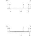
- FIG. 1A is a sectional view taken along line AA
- FIG. 1B is a sectional view taken along line BB.
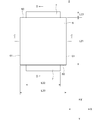
- FIG. 5A is a cross-sectional view taken along the line CC
- FIG. 4B is a cross-sectional view taken along the line DD.
- FIG. 5 is an enlarged perspective view showing a part of FIG. 4. It is a top view showing a part of lining structure of this embodiment. It is a bottom view showing a part of lining structure of this embodiment.
- FIG. 8 is a sectional view taken along the line EE in FIG. 7.
- FIG. 8 is a sectional view taken along line FF of FIG. 7.
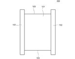
- It is a top view which shows a part of lining structure of a conventional example. It is a top view showing the 1st lining board of the conventional example. It is a top view which shows the 2nd lining board of a prior art example.
- the lining structure is used for the purpose of shielding the surface (lining surface) of a concrete structure, a steel structure, a wooden structure or the like from the environment to protect the structure.
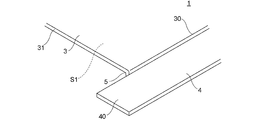
- FIGS. 1 to 3 show the first lining plate 1 of the present embodiment
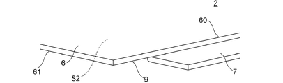
- FIGS. 4 to 6 show the second lining plate 2 of the present embodiment
- FIGS. 7 to 10 show the lining structure 10 of the present embodiment.
- the lining structure 10 is configured by using two types of lining plates, a first lining plate 1 and a second lining plate 2, and a plurality of the first lining plates 1 and the second lining plates 2 are vertically and horizontally arranged on the lining surface. It is constituted by alternately arranging each in the direction.
- the horizontal direction X in FIGS. 1, 4, 7, and 8 is defined as one direction
- the vertical direction Y is defined as the other direction.
- the first lining plate 1 includes a plate body 3 having a rectangular shape in a plan view and a pair of receiving pieces 4.
- the plate main body 3 has a plate shape having a predetermined thickness, and has a pair of opposed first side portions 30 and another pair of opposed second side portions 31.
- the first side portion 30 is a portion where the receiving piece 4 protrudes
- the second side portion 31 is a first side portion of the plate body 6 of the second lining plate 2 that is adjacently arranged. It is a part to be matched with 60.
- a region having a predetermined width from the second side 31 of the plate body 3 is a covering region that is superimposed on the receiving piece 7 of the second lining plate 2 that is arranged adjacently.
- the thickness of the plate body 3 is not particularly limited, but is preferably 0.01 mm or more, more preferably 0.1 mm or more and 5.0 mm or less, and still more preferably 0.5 mm or more and 2.0 mm or less.
- the receiving piece 4 has a plate shape having the same thickness as the plate body 3.
- the receiving piece 4 protrudes outward from the first side 30 of the plate body 3 through the stepped portion 5 having an L-shaped cross section, and the plate body 3 is provided between the receiving piece 4 and the plate body 3.
- a step corresponding to the thickness of the film As a result, a space S1 is formed below the plate body 3 due to a step difference with the receiving piece 4, and the receiving piece 7 of the second lining plate 2 adjacent to this space S1 is introduced.
- the receiving piece 4 has a length equal to or larger than the entire length of the first side 30 of the plate body 3. In the present embodiment, the receiving piece 4 has a length that is greater than the entire length of the first side 30 of the plate body 3, and both ends in the length direction are each second side of the plate body 3.
- Each of the projections 40 protrudes from the projection 31.
- the second lining plate 2 includes a plate main body 6 having a rectangular shape in a plan view, and a pair of receiving pieces 7.
- the plate body 6 has a plate shape having the same thickness as the plate body 3 of the first lining plate 1, and has a pair of opposed first side portions 60 and another pair of opposed second side portions 61. have.
- the first side portion 60 is a portion where the receiving piece 7 protrudes
- the second side portion 61 is formed on the first side portion 30 of the plate body 3 of the first lining plate 1 that is adjacently arranged. This is the part to be matched.
- a region having a predetermined width from the second side portion 61 of the plate body 6 is a covering region that is superimposed on the receiving pieces 4 of the first lining plate 1 arranged adjacent to each other.
- the receiving piece 7 has a plate shape having the same thickness as the plate body 6.
- the receiving piece 7 protrudes outward from the first side 60 of the plate body 6 via the stepped portion 8 having an L-shaped cross section, and the plate body 6 is provided between the receiving piece 7 and the plate body 6.
- a step corresponding to the thickness of the film As a result, a space S2 is formed below the plate body 6 due to a step difference with the receiving piece 7, and the receiving piece 4 of the first lining plate 1 adjacent to the space S2 is introduced.
- the receiving piece 7 has a length smaller than the entire length of the first side portion 60 of the plate body 6, and has a space 9 in which the receiving piece 7 does not exist outside each of both ends in the length direction. ing.
- the space portion 9 is located on both sides of the cover area of the plate body 6 and is connected to the space S2 below the plate body 6, and the receiving piece of the first lining plate 1 is provided below the cover area of the plate body 6.
- the protrusions 40 at both ends of the receiving piece 4 are located in the space 9. That is, the receiving piece 7 is provided on the first side portion 60 of the plate-like body 6 over the entire length or almost the entire length of the region excluding the covering region.
- the length L10 of the plate body 3 of the first lining plate 1 in one direction is the length L20 of the plate body 6 of the second lining plate 2 in one direction (lateral direction X in the illustrated example). It is set to be the same or almost the same.
- the length L11 of the plate body 3 of the first lining plate 1 in the other direction is the length of the plate body 6 of the second lining plate 2 in the other direction (vertical direction Y in the illustrated example).
- the length L21 is set to be the same or almost the same as L21. That is, when the first lining plate 1 and the second lining plate 2 are combined, the first side portion 31 (between the pair of receiving pieces 4) of the first lining plate 1 receives the receiving of the second lining plate 2.
- the piece 7 and one receiving piece 4 of each of the other two first lining plates 1 are arranged without any gap or with some gap.
- the length L20 of the plate body 6 of the second lining plate 2 is the same as the sum of the length L22 of the receiving piece 7 of the second lining plate 2 and the width L13 of the two receiving pieces 4 of the first lining plate 1. Or it is set so that it may become substantially the same.
- the length L12 of the receiving piece 4 of the first lining plate 1 is equal to the length of the second lining plate 2 in the other direction (vertical direction Y in the illustrated example) (that is, the length L21 of the plate body 6 and the two receiving portions). (The sum with the width L23 of the piece 7).
- the first lining plate 1 and the second lining plate 2 can be formed of, for example, a metal material, an alloy material, a nonmetal material, or a composite material of a nonmetal material and a metal material. Among them, it is preferable to form the first lining plate 1 and the second lining plate 2 with a metal material or an alloy material, because the butting portions of the first and second lining plates 1 and 2 can be joined by welding. .
- a material having desired characteristics is used as the metal material or alloy material according to the purpose of the lining.
- the metal material having corrosion resistance for example, titanium, tantalum, niobium, hafnium, nickel, aluminum, or the like can be used.
- the alloy material having corrosion resistance in addition to the alloy containing the above-described metal as a main component, Stainless steel or the like can be used.
- a metal material or the like which is formed by depositing a corrosion-resistant material on the surface by surface treatment such as plating, PVD, or CVD may be used, but from the viewpoint of corrosion resistance and cost, titanium and titanium are mainly used. It is preferable to use a titanium alloy or stainless steel.
- Non-metallic materials include, for example, thermoplastic polymer materials such as polyethylene resin, polypropylene resin, polyamide resin, acrylic resin, and polyvinyl chloride resin, and thermosetting polymer materials such as phenol resin, urea resin, and epoxy resin.
- FRP which is a composite material of an unsaturated polyester resin and glass fiber or the like, can be used.
- the use of these materials not only facilitates the construction of the lining structure 10 due to the weight reduction of the materials, but also can impart corrosion resistance.
- the lining plate has flexibility and can impart flexibility to the lining structure 10, so that the concrete structure, steel structure, It is possible to increase the adhesion to the wooden structure.
- nonmetallic material fine ceramics formed by sintering alumina, magnesia, zirconia, silicon carbide, silicon nitride, a mixture thereof, or the like, or clay, silica, feldspar, or the like is sintered.
- ceramics such as brick, porcelain, glass, etc. are used, heat resistance and wear resistance can be imparted.
- a composite material of a metal material and a nonmetal material such as plastics it is possible to provide a high protection effect even with an inexpensive material by utilizing each other's characteristics.
- the first lining plate 1 and the second lining plate 2 are formed by, for example, forming a single flat plate material formed by a known forming method at a boundary portion between the plate bodies 3 and 6 and the receiving pieces 4 and 7 by a known processing method. To form the bent portions 5 and 8.
- the lining structure 10 is assembled by alternately arranging a plurality of the first lining plates 1 and the second lining plates 2 having the above-described configuration in the horizontal direction X and the vertical direction Y. 7 to 10 show a state in which the lining structure 10 is installed on an inner wall surface (a lining surface) of a water treatment tank of a concrete structure.
- the receiving pieces 4 and 7 of the first and second lining plates 1 and 2 can be fixed to the lining surface by an anchor or an adhesive (not shown) or a combination thereof.
- the second side portion 61 of the second lining plate 2 is adjacent in one direction (the horizontal direction X in the illustrated example).
- the first lining plate 1 is arranged so as to be superimposed on the receiving piece 4 and to abut against the first side 30 of the first lining plate 1.
- the second side 31 of the first lining plate 1 is overlapped with the receiving piece 7 of the adjacent second lining plate 2 and the second lining plate 2 They are arranged so as to abut on the first side portion 60.
- the end (projection 40) of the receiving piece 4 in the longitudinal direction of the first lining plate 1 is connected to the second lining plate adjacent to the first lining plate 1 in one direction (lateral direction X in the illustrated example).
- 2 of the first lining plate 1 protruding from the first side 60 of the second lining plate 2 and located in the space 9 outside the receiving piece 7 of the second lining plate 2 and obliquely adjacent to the first lining plate 1. It is located inside the longitudinal end (projection 40) of the receiving piece 4 on the back side (the lower space S1) of the second side 31.
- the receiving piece 7 of the second lining plate 2 adjacent in the other direction is formed by a pair of receiving pieces 4. Between the receiving pieces 4 and the receiving pieces 7, the end (projecting portion) of the receiving piece 4 on one side of the first lining plate 1 that is obliquely adjacent to the first lining plate 1. 40) are introduced to interrupt each.
- butted portions of the plate bodies 3 and 6 are joined by welding such as TIG welding, an adhesive, or a combination thereof.
- welding such as TIG welding, an adhesive, or a combination thereof.
- the adhesion of the butted portion is improved, and the intrusion of water or the like can be prevented.
- welding and bonding can be reliably performed by the receiving pieces 4 and 7 on the back surface side, so that the reliability of adhesion such as water tightness can be improved, and the construction accuracy can be improved.
- the receiving pieces 4 and 7 existing on the back side can be used as abutment plates (back plates) of the butted portions. It is possible to prevent welding quality deterioration due to melting and volatile components of concrete.
- the adhesive may be epoxy-based adhesive, acrylic-based adhesive, silicone-based adhesive, modified silicone-based adhesive, natural rubber-based adhesive, or synthetic rubber-based adhesive. , Urethane-based adhesives, polymer cements and the like.
- the adhesive is applied to the back surfaces of the plate bodies 3 and 6, for example. And filled with an adhesive or the like. Thereby, the rigidity of the plate bodies 3 and 6 of the first and second lining plates 1 and 2 is increased, and the strength of the lining structure 10 can be improved.
- the lining structure 10 of the present embodiment As described above, in the lining structure 10 of the present embodiment, as shown in FIGS. 7 and 8, two types of lining plates 1 and 2 are arranged in a staggered manner, and the lining plate 1 (2) receives the lining plate 1 (2).
- the plate body 6 (3) of the other lining plate 2 (1) is overlaid on the piece 4 (7), and the plate body 3 (6) of the one lining plate 1 (2) and the other lining plate 2 (1).
- the protrusion 40 which is an end in the length direction of the receiving piece 4 of the first lining plate 1 is a protrusion which is an end in the length direction of the receiving piece 4 of the first lining plate 1 which is adjacent in an oblique direction. 40, and are arranged so as to be located in the space 9 of the second lining plate 2 adjacent in one direction (lateral direction X in the illustrated example).
- the first and second lining plates 1 and 2 that are arranged in the other direction are the first lining.
- a pair of receiving pieces 4 of the plate 1 a receiving piece 7 of the second lining plate 2 and an end of the receiving piece 4 on one side of the first lining plate 1 laterally adjacent to the second lining plate 2 ( The protruding portions 40) are sandwiched, and they are arranged in a state where they are regulated so as not to be displaced in one direction (the horizontal direction X in the illustrated example) due to the contact therebetween.
- first and second lining plates 1 and 2 which are arranged in rows in the other direction (vertical direction Y in the illustrated example), are displaced in one direction (horizontal direction X in the illustrated example) due to a displacement in one direction (example in the illustrated example).
- the abutting portion between the lining plates 1 and 2 adjacent in the lateral direction X) is prevented from being opened carelessly.
- the first and second lining plates 1 and 2 are end portions of the receiving pieces 4 of the first lining plate 1 that are obliquely adjacent to each other. Since the (projecting portions 40) are engaged with each other, the displacement in the lateral direction X is prevented. Therefore, when a plurality of lining plates 1 and 2 are combined, even if an external force acts in such a direction that rows adjacent to each other in one direction (the horizontal direction X in the illustrated example) are separated from each other, the external force acts in one direction (the horizontal direction X in the illustrated example).
- the lining structure 10 of the present embodiment as shown in FIG. 7, when a plurality of lining plates 1 and 2 are combined, when joining the seams of the adjacent lining plates 1 and 2 by welding or the like, Joints extending in one direction (the horizontal direction X in the illustrated example) and the other direction (the vertical direction Y in the illustrated example) are both straight lines, and the joints form a lattice shape. Therefore, the joining work of the seam can be performed efficiently, and also in this regard, the workability during the construction of the lining structure can be improved.
- the end (the protruding portion 40) of the receiving piece 4 of the first lining plate 1 is connected to the second side portion 31 of the first lining plate 1 which is obliquely adjacent. Since it is located on the back side, when the lining plates 1 and 2 are lifted off the lining surface by an external force such as seismic force or the like and are about to be peeled off, the protruding portion 40 hits the back surface of the plate body 3 of the first lining plate 1 and is lined. Since the lifting of the plates 1 and 2 is prevented, the joint of the lining plates 1 and 2 can be prevented from being loosened.
- the lining structure 10 of the present embodiment it is possible to finish the surfaces of the continuous lining plates 1 and 2 to a smooth surface (flat surface) without unevenness. Therefore, when the lining structure 10 is applied to a structure in contact with the liquid, the flow path resistance can be reduced. Even if the receiving pieces 4 and 7 of the lining plates 1 and 2 are fixed to the lining surface with an adhesive, the adhesive is covered with the receiving pieces 4 and 7 and the plate bodies 3 and 6 and is exposed to the liquid. Since no harmful substances are dissolved in the processing solution, no problem occurs even if an inexpensive and poorly durable adhesive is used.
- the anchor bolts are also not exposed, so that elution of harmful substances can be prevented, and the cost can be reduced. Even if an anchor bolt having poor durability is used, no problem occurs.
Landscapes
- Engineering & Computer Science (AREA)
- Architecture (AREA)
- Civil Engineering (AREA)
- Structural Engineering (AREA)
- Finishing Walls (AREA)
- Butt Welding And Welding Of Specific Article (AREA)
- Road Paving Structures (AREA)
Abstract
L'invention concerne une structure de garnissage présentant une ouvrabilité améliorée pour la construction. Dans une structure 10 de garnissage, un second côté 61 d'une seconde plaque 2 de garnissage chevauche une partie réceptrice 4 d'une première plaque 1 de garnissage adjacente et s'appuie sur un premier côté 30 de la première plaque 1 de garnissage dans une des directions verticale et horizontale (direction horizontale X). De plus, dans la structure 10 de garnissage, un second côté 31 d'une première plaque 1 de garnissage chevauche une partie réceptrice 7 d'une seconde plaque 2 de garnissage adjacente et s'appuie sur un premier côté 60 de la seconde plaque 2 de garnissage dans l'autre des directions verticale et horizontale (direction verticale Y). En outre, dans la structure 10 de garnissage, une extrémité 40 dans la direction longitudinale de la partie réceptrice 4 d'une première plaque 1 de garnissage est située à l'intérieur d'une extrémité 40 dans la direction longitudinale d'une partie réceptrice 4 diagonalement adjacente d'une première plaque 1 de garnissage, les deux extrémités 40 étant en interaction mutuelle, et est positionnée dans un espace 9 de la seconde plaque 2 de garnissage adjacente dans la direction considérée (direction horizontale X).
Applications Claiming Priority (2)
| Application Number | Priority Date | Filing Date | Title |
|---|---|---|---|
| JP2018-137473 | 2018-07-23 | ||
| JP2018137473A JP6513863B1 (ja) | 2018-07-23 | 2018-07-23 | ライニング構造 |
Publications (1)
| Publication Number | Publication Date |
|---|---|
| WO2020022061A1 true WO2020022061A1 (fr) | 2020-01-30 |
Family
ID=66530745
Family Applications (1)
| Application Number | Title | Priority Date | Filing Date |
|---|---|---|---|
| PCT/JP2019/027294 Ceased WO2020022061A1 (fr) | 2018-07-23 | 2019-07-10 | Structure de garnissage |
Country Status (3)
| Country | Link |
|---|---|
| JP (1) | JP6513863B1 (fr) |
| TW (1) | TW202012757A (fr) |
| WO (1) | WO2020022061A1 (fr) |
Citations (3)
| Publication number | Priority date | Publication date | Assignee | Title |
|---|---|---|---|---|
| US2649172A (en) * | 1947-06-02 | 1953-08-18 | Architectural Porcelain Constr | Architectural panel |
| US6463708B1 (en) * | 1999-11-15 | 2002-10-15 | Victor W. Anderson | Roof shingle and system |
| JP3709485B1 (ja) * | 2004-10-08 | 2005-10-26 | 株式会社昭和 | ライニング構造 |
-
2018
- 2018-07-23 JP JP2018137473A patent/JP6513863B1/ja active Active
-
2019
- 2019-07-10 WO PCT/JP2019/027294 patent/WO2020022061A1/fr not_active Ceased
- 2019-07-18 TW TW108125425A patent/TW202012757A/zh unknown
Patent Citations (3)
| Publication number | Priority date | Publication date | Assignee | Title |
|---|---|---|---|---|
| US2649172A (en) * | 1947-06-02 | 1953-08-18 | Architectural Porcelain Constr | Architectural panel |
| US6463708B1 (en) * | 1999-11-15 | 2002-10-15 | Victor W. Anderson | Roof shingle and system |
| JP3709485B1 (ja) * | 2004-10-08 | 2005-10-26 | 株式会社昭和 | ライニング構造 |
Also Published As
| Publication number | Publication date |
|---|---|
| JP2020016018A (ja) | 2020-01-30 |
| TW202012757A (zh) | 2020-04-01 |
| JP6513863B1 (ja) | 2019-05-15 |
Similar Documents
| Publication | Publication Date | Title |
|---|---|---|
| KR100956691B1 (ko) | 라이닝 구조 | |
| US8266862B2 (en) | Prefabricated wall/floor panel | |
| CN104169498B (zh) | 膨胀接头 | |
| CN102137978B (zh) | 由塑料制成的具有机械的锁定棱边的地板嵌板 | |
| US20110073747A1 (en) | Brick formliner apparatus and system | |
| CN103328146B (zh) | 面板接合结构 | |
| CN103797196A (zh) | 梁和柱的接合结构以及接合部件 | |
| WO2020022061A1 (fr) | Structure de garnissage | |
| KR101706086B1 (ko) | 단열재가 결합된 데크플레이트 및 이를 이용한 단열재가 결합된 트러스거더형 데크패널 | |
| CN100529295C (zh) | 衬砌构造 | |
| KR20150061767A (ko) | 서로 다른 두께의 강판콘크리트 벽체간 접합 구조 | |
| JP2023010118A (ja) | コンクリート構造物の補強パネルおよび補強構造 | |
| KR101857742B1 (ko) | 라이닝패널을 포함하는 탱크구조 | |
| JP4446868B2 (ja) | 溝構造 | |
| JP2714853B2 (ja) | パネル式耐食構造体 | |
| JP6534303B2 (ja) | セグメントの接合構造 | |
| JP2006090039A (ja) | 耐力壁構造 | |
| JPH09316856A (ja) | 水路構造 | |
| JP2002004551A (ja) | 板材の接合部材及び板材の接合構造 | |
| JP2017214795A (ja) | セグメントおよびセグメントの継手構造 | |
| KR101459209B1 (ko) | 조립식 바닥재 | |
| JP2021098997A (ja) | 矢板継手止水機構 | |
| JP2020165127A (ja) | 建築板 | |
| KR20060084043A (ko) | 물탱크 라이닝용 코너받이구 | |
| JP2000333753A (ja) | カウンター |
Legal Events
| Date | Code | Title | Description |
|---|---|---|---|
| 121 | Ep: the epo has been informed by wipo that ep was designated in this application |
Ref document number: 19841841 Country of ref document: EP Kind code of ref document: A1 |
|
| NENP | Non-entry into the national phase |
Ref country code: DE |
|
| 122 | Ep: pct application non-entry in european phase |
Ref document number: 19841841 Country of ref document: EP Kind code of ref document: A1 |