WO2020022449A1 - Support d'aiguille de revêtement, élément de revêtement, dispositif de revêtement et procédé de revêtement - Google Patents
Support d'aiguille de revêtement, élément de revêtement, dispositif de revêtement et procédé de revêtement Download PDFInfo
- Publication number
- WO2020022449A1 WO2020022449A1 PCT/JP2019/029268 JP2019029268W WO2020022449A1 WO 2020022449 A1 WO2020022449 A1 WO 2020022449A1 JP 2019029268 W JP2019029268 W JP 2019029268W WO 2020022449 A1 WO2020022449 A1 WO 2020022449A1
- Authority
- WO
- WIPO (PCT)
- Prior art keywords
- coating
- outer cylinder
- application
- needle
- liquid material
- Prior art date
- Legal status (The legal status is an assumption and is not a legal conclusion. Google has not performed a legal analysis and makes no representation as to the accuracy of the status listed.)
- Ceased
Links
Images










Classifications
-
- B—PERFORMING OPERATIONS; TRANSPORTING
- B05—SPRAYING OR ATOMISING IN GENERAL; APPLYING FLUENT MATERIALS TO SURFACES, IN GENERAL
- B05C—APPARATUS FOR APPLYING FLUENT MATERIALS TO SURFACES, IN GENERAL
- B05C1/00—Apparatus in which liquid or other fluent material is applied to the surface of the work by contact with a member carrying the liquid or other fluent material, e.g. a porous member loaded with a liquid to be applied as a coating
- B05C1/02—Apparatus in which liquid or other fluent material is applied to the surface of the work by contact with a member carrying the liquid or other fluent material, e.g. a porous member loaded with a liquid to be applied as a coating for applying liquid or other fluent material to separate articles
-
- B—PERFORMING OPERATIONS; TRANSPORTING
- B05—SPRAYING OR ATOMISING IN GENERAL; APPLYING FLUENT MATERIALS TO SURFACES, IN GENERAL
- B05D—PROCESSES FOR APPLYING FLUENT MATERIALS TO SURFACES, IN GENERAL
- B05D1/00—Processes for applying liquids or other fluent materials
- B05D1/28—Processes for applying liquids or other fluent materials performed by transfer from the surfaces of elements carrying the liquid or other fluent material, e.g. brushes, pads, rollers
Definitions
- the present invention relates to a coating needle holder, a coating member, a coating device, and a coating method, and more specifically, to a coating needle holder, a coating member, a coating device, and a coating needle for coating a liquid material on a material to be processed using a coating needle.
- a coating needle holder a coating member, a coating device, and a coating needle for coating a liquid material on a material to be processed using a coating needle.
- JP-A-2015-112576 discloses a coating apparatus provided with a coating needle that penetrates a container holding a liquid to be coated and that is movable so that a tip portion can move in and out of the container.
- a two-component adhesive to a material to be treated, for example, using a coating device having a coating needle disclosed in JP-A-2015-112576, two coating members including the coating needle are used. Then, each adhesive is applied. Specifically, the first liquid adhesive is applied using one application member, and the second liquid adhesive is applied on the applied first liquid adhesive using the other application member.
- the second liquid adhesive mixed in contact with the first liquid adhesive remains at the tip of the coating needle of the other coating member.
- the tip of the application needle becomes thicker due to the hardened adhesive.
- the amount of the second liquid adhesive adhered to the tip of the application needle of the other application member increases, and as a result, the amount of the second liquid adhesive applied gradually increases.
- the tip of the application needle becomes too thick, the application needle cannot be stored in a container holding the second liquid adhesive that is the liquid to be applied.
- the liquid cannot be stably applied because the liquid to be applied remains at the tip of the application needle.
- the present invention has been made to solve the above-described problems, and an object of the present invention is to provide a coating needle holder, a coating member, and a coating material that can stably perform supply of a liquid material using a coating needle.
- An object of the present invention is to provide a coating apparatus and a coating method.
- the coating needle holder includes a coating needle for supplying a liquid material to a material to be processed, an outer cylinder, and a first driving unit.
- the outer cylinder surrounds the outer periphery of the application needle and includes a first end located closer to the tip of the application needle.
- the first drive unit moves the outer cylinder relative to the application needle in a first direction that is the direction in which the application needle extends.
- the first drive unit is configured to move the tip of the application needle from the first state to the first end of the outer cylinder in a first state in which the tip of the application needle is retracted into the outer cylinder from the first end of the outer cylinder. The second state is switched.
- a coating device includes the coating needle holder and a holding table.
- the holding table holds a processing target material to which the liquid material is applied by the application needle.
- a coating method is a coating method using a first coating needle holder and a second coating needle holder, and includes a first coating step and a second coating step.
- the first application step the first liquid material is applied to the processing target material using the first application needle holder.
- a second liquid material is applied to the processing target material after the first application step.
- a second coating needle holder is used.
- the second application needle holder includes an application needle for supplying a second liquid material to the material to be processed, and an outer cylinder surrounding the outer periphery of the application needle and including a first end located closer to the tip of the application needle.
- the second liquid material is supplied to the material to be processed by dropping the second liquid material from the tip of the coating needle.
- a coating member according to the present disclosure includes the coating needle holder and a second driving unit.
- the second drive moves the application needle and the outer cylinder in the first direction.
- the application member includes an application needle for supplying a liquid material to a material to be processed, an outer cylinder, a first drive unit, and a second drive unit.
- the outer cylinder surrounds the outer periphery of the application needle and includes a first end located closer to the tip of the application needle.
- the first drive unit moves the outer cylinder relative to the application needle in a first direction that is the direction in which the application needle extends.
- the second drive moves the application needle and the outer cylinder in the first direction.
- the first drive unit is configured to move the tip of the application needle from the first state to the first end of the outer cylinder in a first state in which the tip of the application needle is retracted into the outer cylinder from the first end of the outer cylinder. The second state is switched.
- a coating apparatus includes the above-described coating member and a holding table.
- the holding table holds a processing target material to which the liquid material is applied by the application needle.
- a coating method includes a coating needle for supplying a liquid material to a material to be processed, an outer cylinder that surrounds the outer periphery of the coating needle, and includes a first end located closer to a tip of the coating needle.
- This is a coating method using a coating member having: In the coating method, the coating member in which the distal end of the coating needle is retracted into the outer cylinder from the first end of the outer cylinder is set to a first state, and the distal end of the coating needle and the first of the outer cylinder are placed in the first state. A step of holding the liquid material in an inner region of the outer cylinder located between the ends is performed.
- a step of causing at least a part of the liquid material to project outside the first end of the outer cylinder by changing the application member from the first state to the second state is performed.
- a step of bringing at least a part of the liquid material protruding outward from the first end into contact with the material to be processed is performed.
- FIG. 2 is a schematic diagram illustrating a coating member of the coating device illustrated in FIG. 1.
- FIG. 2 is a schematic diagram illustrating a coating member of the coating device illustrated in FIG. 1.
- FIG. 4 is a schematic diagram for explaining a configuration of a coating needle holder of the coating device shown in FIG. 3.
- FIG. 4 is a schematic diagram for explaining an operation of a coating needle holder in the coating member shown in FIGS. 2 and 3.
- FIG. 6 is an enlarged schematic diagram of a region VI in FIG. 5.
- FIG. 4 is a schematic diagram for explaining an operation of a coating needle holder in the coating member shown in FIGS. 2 and 3.
- FIG. 8 is an enlarged schematic diagram of a region VIII in FIG. 7.
- 5 is a flowchart of a coating method according to the embodiment. It is a flowchart of the modification of the coating method according to this embodiment. It is a schematic diagram for explaining the 1st modification of the application member and the application needle holder according to this embodiment. It is a schematic diagram for explaining the 2nd modification of the application member and the application needle holder according to this embodiment. It is a schematic diagram for explaining the 2nd modification of the application member and the application needle holder according to this embodiment. It is a mimetic diagram for explaining the 3rd modification of an application member and an application needle holder according to this embodiment.
- FIG. 13 is an enlarged schematic diagram of the same region as that shown in FIG. 6 in a fourth modification of the present embodiment. It is a flowchart of the supply method of the liquid material characteristic of the 4th modification. It is a schematic diagram for explaining the supply method of the liquid material characteristic of the fourth modification. 5 is a flowchart of a coating method of a comparative example. It is a flow chart which shows the 1st example of the application method of the liquid material in the 4th modification of this embodiment schematically. It is a flow chart which shows roughly the 2nd example of the application method of the liquid material in the 4th modification of this embodiment.
- FIG. 1 is a schematic diagram of a coating apparatus according to the present embodiment.
- the coating apparatus according to the embodiment of the present invention illustrated in FIG. 1 includes a processing chamber, a Y-axis table 2, an X-axis table 1, a Z-axis table 3, a coating mechanism, It mainly includes an observation optical system 6, a CCD camera 7 connected to the observation optical system 6, and a control unit.
- the control unit includes a monitor 9, a control computer 10, and an operation panel 8.
- the application mechanism includes a plurality of application members 4. In the coating apparatus shown in FIG. 1, two coating members 4 are installed.
- the application member 4 includes an application needle holder.
- the application needle holder includes an application needle section 24 (see FIG. 4).
- the application needle section 24 has an application needle 24a (see FIG. 4) and an application needle outer cylinder 24b (see FIG. 4, hereinafter referred to as an outer cylinder 24b).
- the detailed configuration of the application needle section 24 will be described later.
- the Y-axis table 2 is installed on the bottom of the processing chamber.
- This Y-axis table 2 is movable in the Y-axis direction.
- a guide portion is provided on the lower surface of the Y-axis table 2.
- the guide section is slidably connected to a guide rail installed on the bottom surface of the processing chamber.
- a ball screw is connected to the lower surface of the Y-axis table 2.
- the upper surface of the Y-axis table 2 is a mounting surface on which the processing target material 5 such as a substrate is mounted.
- the X-axis table 1 is provided on the Y-axis table 2.
- the X-axis table 1 is disposed on a structure installed so as to straddle the Y-axis table 2 in the X-axis direction.
- a moving body to which the Z-axis table 3 is connected is installed so as to be movable in the X-axis direction.
- the moving body is movable in the X-axis direction using, for example, a ball screw.
- the X-axis table 1 is fixed to the bottom of the processing chamber via the above structure. Therefore, the above-described Y-axis table 2 is movable in the Y-axis direction with respect to the X-axis table 1.
- the Z-axis table 3 is installed on the moving body connected to the X-axis table 1 as described above.
- the observation optical system 6 and the coating member 4 are connected to the Z-axis table 3.
- the observation optical system 6 is for observing the application position of the processing target material 5 to be applied.
- the CCD camera converts the observed image into an electric signal.
- the Z-axis table 3 holds the observation optical system 6 and the application member 4 movably in the Z-axis direction.
- the monitor 9 displays image data converted by the above-described CCD camera 7 and output data from the control computer 10.
- the operation panel 8 is used to input a command to the control computer 10.
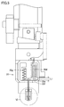
- FIG. 2 and FIG. 3 are schematic views showing the coating member 4 of the coating apparatus shown in FIG.
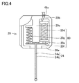
- FIG. 4 is a schematic diagram for explaining the configuration of the coating needle holder in the coating device shown in FIG.
- the above-described application member 4 will be described in more detail with reference to FIGS.
- the two coating members 4 installed in the coating device shown in FIG. 1 have the same configuration.
- the coating member 4 fixed to the Z-axis table 3 shown in FIG. 1 includes a coating needle holder 20 including a coating needle portion 24.
- the application needle portion 24 of the application needle holder 20 includes the application needle 24a and the outer cylinder 24b as described above.
- the outer cylinder 24b is a cylindrical member surrounding the outer periphery of the application needle 24a.
- the outer cylinder 24b is relatively movable with respect to the application needle 24a by the first drive unit 80.
- the application member 4 further includes a second drive unit 40 that moves the application needle holder 20 in the extending direction of the application needle 24a, and a container 21 that holds a liquid material that is a material to be applied.
- the application needle holder 20 is detachably connected to the second drive unit 40.
- the structure for connecting the coating needle holder 20 to the second drive unit 40 can employ any structure.
- the application needle holder 20 mainly includes the application needle part 24, the application needle support plate 20c, the first driving unit 80, and the holder outer shell 20a, as shown in FIG.
- the first drive unit 80 and the coating needle support plate 20c are arranged inside the holder outer shell 20a.
- the application needle portion 24 is arranged in a state where a part thereof protrudes outward from a lower portion of the holder outer shell 20a.
- the root of the coating needle 24a is fixed to the tip of the coating needle support plate 20c.
- the root of the application needle 24a is an end of the application needle 24a located inside the holder outer shell 20a and facing the application needle support plate 20c.
- the tip of the application needle 24a is an end opposite to the root of the application needle 24a.
- the root of the outer cylinder 24b is fixed to the movable plate 20f.
- the root of the outer cylinder 24b is an end located inside the holder outer shell 20a in the outer cylinder 24b and facing the movable plate 20f.
- the root of the outer cylinder 24b is a part of the outer cylinder 24b surrounding the root of the application needle 24a.
- the movable plate 20f is formed with a hole through which the coating needle 24a is inserted at a portion where the outer cylinder 24b is fixed.
- the application needle 24a is disposed inside the outer cylinder 24b through the corresponding hole of the movable plate 20f.
- the first drive section 80 includes the movable plate 20f, an electromagnetic solenoid 20d, a movable shaft 20e, and a spring 20g.
- the movable plate 20f includes a first portion to which one end of the movable shaft 20e is fixed, and a second portion to which one end of the spring 20g is fixed.
- the other end of the spring 20g opposite to the one end fixed to the movable plate 20f is fixed to the application needle support plate 20c.
- the spring 20g urges the movable plate 20f toward the tip of the application needle 24a.
- the other end of the spring 20g may be fixed to the inner wall of the outer shell 20a.
- the movable shaft 20e is movable by an electromagnetic solenoid 20d.
- the electromagnetic solenoid 20d is electrically connected to the coating needle holder side electrode 20b.
- the application needle holder side electrode 20b is connected to the movable part side electrode 46a of the movable part 46 to which the application needle holder 20 is fixed. Electric power is supplied to the electromagnetic solenoid 20 d from outside the coating member 4 via the movable portion side electrode 46 a and the coating needle holder side electrode 20 b.
- a spring 20g and an electromagnetic solenoid 20d are connected to a second surface of the movable plate 20f opposite to the first surface of the outer cylinder 24b. More specifically, the electromagnetic solenoid 20d is connected to the second surface of the movable plate 20f via the movable shaft 20e.
- the spring 20g, the movable shaft 20e, and the electromagnetic solenoid 20d are arranged on the side opposite to the outer cylinder 24b when viewed from the movable plate 20f.
- the application needle 24a is disposed inside the outer cylinder 24b.
- the tip of the coating needle 24a and the outer cylinder 24b which is the end opposite to the root, is located on the opposite side to the spring 20g and the electromagnetic solenoid 20d when viewed from the movable plate 20f.
- the spring 20g and the electromagnetic solenoid 20d are arranged so as to sandwich the coating needle support plate 20c.
- the central axis of the spring 20g and the electromagnetic solenoid 20d is arranged along the extending direction of the application needle 24a. Note that the central axis of the spring 20g means a winding center around which a wire constituting the spring 20g, which is a coil spring, is wound.
- the central axis of the electromagnetic solenoid 20d means a winding center around which a conductive wire constituting the electromagnetic solenoid 20d is wound.
- the outer cylinder 24b can be moved by the electromagnetic solenoid 20d via the movable shaft 20e and the movable plate 20f.
- the electromagnetic solenoid 20d operates to move the movable shaft 20e upward (in a direction away from the tip end side opposite to the root of the coating needle 24a)
- the outer cylinder 24b is moved to the position of the coating needle 24a. It moves relatively to the application needle 24a toward the root side, that is, in the direction approaching the application needle support plate 20c.
- the second drive section 40 includes a servomotor 41, a cam 43, a bearing 44, a cam connecting plate 45, and a movable section 46.
- the servo motor 41 is installed such that the rotation axis extends in a direction along the Z-axis direction shown in FIG. 1, for example.
- a cam 43 is connected to the rotation shaft of the servo motor 41.
- the cam 43 is rotatable about a rotation axis of the servomotor 41.
- the cam 43 includes a central portion connected to the rotation shaft of the servomotor 41, and a flange portion connected to one end of the central portion.
- the upper surface of the flange portion (the surface on the servo motor 41 side) is a cam surface.
- the cam surface is formed in an annular shape along the outer periphery of the center. As shown in FIGS. 2 and 3, the cam surface is formed in a slope shape so that the distance from the bottom surface of the flange portion varies.
- the cam surface has an upper end flat region where the distance from the bottom surface of the flange portion is the largest, and a lower end flat region where the distance from the bottom surface of the flange portion is arranged with a distance from the upper end flat region and A slope portion connecting the upper end flat region and the lower end flat region.
- a bearing 44 is arranged in contact with the cam surface of the cam 43.
- the bearing 44 is disposed in a specific direction (to the right of the servomotor 41) when viewed from the cam 43 as shown in FIGS.
- the bearing 44 keeps contact with the cam surface when the cam 43 rotates due to the rotation of the rotation shaft of the servomotor 41.
- a cam connecting plate 45 is connected to the bearing 44. In the cam connecting plate 45, the other end opposite to the one end connected to the bearing 44 is fixed to the movable portion 46.
- the movable part 46 is connected to an application needle holder storage part.
- the coating needle holder 20 described above is stored in the coating needle holder storage section.
- a first connection member such as a magnet may be arranged on a surface of the application needle holder 20 facing the application needle holder storage unit.
- a second connection member such as a magnet or a magnetic material, which can fix the above-described first connection member on the application needle holder 20 side may be arranged on the application needle holder storage section side.
- a container 21 is arranged below the application needle holder 20.
- the application needle portion 24 is held in the container 21 in a state of being inserted.
- a fixed pin is provided on the movable part 46.
- the other holding pin is installed on the gantry holding the servomotor 41.
- a spring is provided to connect between these two fixing pins. Due to this spring, the movable portion 46 is in a state of receiving a tensile force toward the container 21. Further, the tensile force by the spring acts on the bearing 44 via the movable portion 46 and the cam connecting plate 45. The bearing 44 is kept pressed against the cam surface of the cam 43 by the tensile force of the spring 50.
- the movable section 46 and the application needle holder storage section are connected to a linear guide installed on the gantry.
- the linear guide is arranged to extend in the Z-axis direction. Therefore, the movable part 46 and the application needle holder storage part are movable along the Z-axis direction.
- FIG. 2 shows a state in which the application needle portion 24 is relatively displaced upward in the Z-axis direction
- FIG. 3 shows a state in which the application needle portion 24 is relatively displaced downward in the Z-axis direction.
- FIGS. 5 and 7 are schematic diagrams for explaining the operation of the application needle holder 20 in the application member shown in FIGS. 2 and 3.
- FIG. 6 is an enlarged schematic diagram of a region VI in FIG.
- FIG. 8 is an enlarged schematic diagram of a region VIII in FIG. 5 and 6 show a coating standby state, and FIGS. 7 and 8 show a coating state.
- the outer cylinder 24b stands by while being relatively lowered with respect to the coating needle 24a.
- the distance between the lower end of the electromagnetic solenoid 20d and the movable plate 20f is a distance L1.
- the tip of the application needle 24a is housed in the back of the outer cylinder 24b.
- a part of the liquid material 70 is held between the tip of the outer cylinder 24b and the tip of the application needle 24a and inside the outer cylinder 24b.
- the outer cylinder 24b is relatively raised with respect to the application needle 24a by the operation of the electromagnetic solenoid 20d.
- the distance between the lower end of the magnetic solenoid 20d and the movable plate 20f is a distance L2 smaller than the distance L1 shown in FIG.
- a part of the liquid material 70 held inside the distal end side of the outer cylinder 24b is pushed out and accumulates at the distal end of the application needle 24a.
- the liquid material is supplied to the surface of the processing target material by applying the accumulated liquid material to the surface of the processing target material.
- Such a coating standby state and a coating state are repeatedly performed.
- the tip of the application needle 24a is stored in the container 21 of the liquid material. Thereafter, the outer cylinder 24b is relatively lowered with respect to the application needle 24a by the operation of the electromagnetic solenoid 20d. As a result, as shown in FIGS. 5 and 6, the tip of the application needle 24a is housed inside the outer cylinder 24b, and a part of the liquid material 70 is held again inside the tip of the outer cylinder 24b.
- the tip of the application needle 24a is The liquid material may be stored in the container 21. Also in this case, a part of the liquid material 70 flows into the inside of the distal end side of the outer cylinder 24b in which the distal end of the application needle 24a is stored.
- the actuator for moving the outer cylinder 24b up and down is not limited to the above-described electromagnetic solenoid 20d, but may be any mechanism.
- any actuator such as an air cylinder or an electric cylinder, or a reciprocating mechanism such as a cam mechanism or a crank mechanism may be used as an actuator for moving the outer cylinder 24b relative to the application needle 24a.
- the electromagnetic solenoid 20d is used as the actuator, effects such as a reduction in the size and weight of the coating needle holder 20 and a reduction in the operation time of the outer cylinder 24b can be obtained.
- FIG. 9 is a schematic diagram for explaining a coating method as a comparative example.
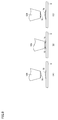
- FIG. 10 is a schematic diagram for explaining a coating method according to the present embodiment. The coating method according to the present embodiment shown in FIG. 10 will be described in comparison with the coating method as a comparative example shown in FIG. 9 and 10 show a case where another liquid material is applied to the liquid material 75 previously applied to the surface of the material 5 to be processed.
- the width of the distal end is gradually narrowed, and the application needle 124 having a flat distal end surface is used.
- the amount of the liquid material 70 adhering to the flat tip surface of the application needle 124 is substantially determined by the viscosity of the liquid material 70. Therefore, it has been difficult to arbitrarily control the amount of the liquid material 70 attached to the front end surface. Generally, the amount of the liquid material 70 attached to the tip end surface of the application needle 124 is very small.
- the liquid material 70 is applied to the surface of the processing target material 5 by using such an application needle 124 so as to overlap the liquid material 75 previously applied.
- a mixed liquid material 77 in which the liquid material 75 previously applied and the liquid material 70 attached to the tip of the application needle 124 are mixed together also adheres to the tip side.
- the adhesive hardens at the tip of the application needle 124 and adversely affects subsequent application.
- the liquid materials 70 and 75 are not a two-liquid adhesive, if the liquid material 70 attached to the tip of the application needle 124 is contaminated with the liquid material 75 applied earlier, the application needle The liquid material 70 held in the container of the coating material containing 124 is also contaminated.
- the coating method according to the present embodiment shown in FIG. 10 first, as shown in FIG. A part 70a of the liquid material is held in a space between the one end 26 and the tip 25 of the application needle 24a. Thereafter, the outer cylinder 24b is raised relatively to the application needle 24a. As a result, as shown in FIG. 10B, the liquid material 70a (see FIG. 10A) is extruded from the space inside the first end 26 of the outer cylinder 24b to the outside of the first end 26, and the liquid droplets are dropped. 71.
- the tip 25 of the application needle 24a may be located on the same plane as the first end 26 of the outer cylinder 24b.
- the tip 25 of the application needle 24a may be arranged inside the first end 26 of the outer cylinder 24b, or may be arranged outside the first end 26. Since the liquid material 70a to be the droplet 71 is held inside the outer cylinder 24b in this manner, the volume of the droplet 71 is smaller than that of the liquid material 70 attached to the tip of the application needle 124 in the comparative example shown in FIG. Be larger than volume.
- the application needle 24a and the outer cylinder 24b are relatively brought closer to the processing target material 5.
- the application needle 24 a and the outer cylinder 24 b are moved in the direction indicated by the arrow toward the material 5 to be processed from the configuration of the application member 4.
- the processing target material 5 may be moved toward the application needle 24a and the outer cylinder 24b.
- the droplet 71 held on the tip side of the coating needle 24a and the outer cylinder 24b comes into contact with the liquid material 75 on the surface of the processing target material 5.
- the lower end of the droplet 71 is brought into contact with the liquid material 75 on the surface of the processing target material 5.
- the application needle 24a and the outer cylinder 24b are moved in the direction of the arrow from the processing target material 5 side.
- the liquid material 75 previously applied to the processing target material 5 is used as the first liquid material of the two-component adhesive, and the liquid material droplet 71 to be applied later is used as the second liquid material. It may be used as the material of the second liquid of the adhesive.
- the processing target material 5 may be a solid member having a flat plate or a curved surface, but may be a liquid or gel member, and has a surface on which the liquid material 75 can be disposed. Anything is good.
- the tip 25 of the application needle 24a may be contaminated by the first liquid. Performance can be reduced. As a result, stable application becomes possible.
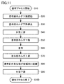
- FIG. 11 is a flowchart of the coating method according to the present embodiment. The coating method according to the present embodiment will be described with reference to FIG. 11 and FIGS. 5 to 10 as appropriate.
- a coating process is started (S10). Specifically, for example, control of each device of the coating apparatus is started by the control computer 10.
- the X-axis table 1, the Y-axis table 2, the Z-axis table 3, and the like are controlled so that, for example, the application member 4 is disposed at a position facing the processing target material 5.
- the tip 25 of the application needle 24a of the application needle holder 20 is located inside the outer cylinder 24b.
- the distal end of the outer cylinder 24b is in a state of being disposed inside the container 21.
- a liquid material 70a is disposed inside the distal end side of the outer cylinder 24b.
- the lowering of the application needle holder is started (S20). Specifically, the application needle holder 20 is moved to the container 21 by the second drive unit 40. As a result, both the outer cylinder 24b and the application needle 24a protrude from the bottom surface of the container 21. At this time, the tip 25 of the application needle 24a is retracted from the first end 26 of the outer cylinder 24b as shown in FIG. A liquid material 70a is held between the first end 26 of the outer cylinder 24b and the tip 25 of the application needle 24a.
- the outer cylinder 24b is raised (S40). Specifically, as described with reference to FIGS. 7 and 8, the electromagnetic solenoid 20d is driven to pull up the outer cylinder 24b to the root side of the outer cylinder 24b. As a result, as shown in FIG. 10B, the tip 25 of the application needle 24a relatively moves to the first end 26 side of the outer cylinder 24b, and the liquid droplets fall below the first end 26 of the outer cylinder 24b. 71 are formed.
- the lowering of the application needle holder is started again (S50).
- the application needle 24a holding the droplet 71 approaches the processing target material 5.
- the application step (S60) of supplying the liquid material so as to be applied to the surface of the processing target material 5 is performed.
- the distance between one of the tip 25 of the coating needle 24a or the first end 26 of the outer cylinder 24b close to the processing target material 5 and the surface of the processing target material 5 is: It is preferable that the diameter be greater than zero and less than the diameter of the droplet 71.
- the liquid material can be applied to the surface of the descending target material 55 without the coating needle 24a or the outer cylinder 24b coming into direct contact with the processing target material 5.
- the diameter of the droplet 71 can be determined in consideration of the viscosity of the liquid material forming the droplet 71 and the like. Further, the diameter can be adjusted by changing the distance by which the tip 25 of the application needle 24a retreats inside the outer cylinder 24b.
- the lifting of the application needle holder is stopped (S80).
- the position of the first end 26 of the outer cylinder 24b is set such that the first end 26 is not exposed to the outside of the container 21 even when the first end 26 is lowered relative to the application needle 24a inside the container 21. It is preferable that the liquid material 70 is kept in the liquid material 70 held in the container 21.
- the outer cylinder 24b is lowered relatively to the application needle 24a (S90).
- the distal end 25 of the application needle 24a is retracted from the first end 26 of the outer cylinder 24b.
- a part of the liquid material 70 inside the container 21 is arranged inside the outer cylinder 24b on the first end 26 side.
- FIG. 12 is a flowchart of a modification of the coating method according to the present embodiment. A modification of the coating method according to the present embodiment will be described with reference to FIG. 12 and FIGS. 5 to 11 as appropriate.
- steps (S10) to (S30) are performed in the same manner as the coating method shown in FIG. Thereafter, as shown in FIG. 12, the outer cylinder 24b is raised while lowering the application needle holder 20 at a low speed (S140). In this step (S140), the application needle holder 20 is moved to the container 21 by the second driving unit 40. The lowering speed of the application needle holder 20 in this step (S140) is lower than the lowering speed of the application needle holder 20 in steps (S20) to (S30). At the same time, the outer cylinder 24b rises relatively to the application needle 24a. Specifically, similarly to the step (S40) of FIG. 11, the electromagnetic solenoid 20d described with reference to FIGS.
- the timing of starting the lowering of the coating needle holder 20 and the timing of starting the raising of the outer cylinder 24b may be the same.
- the start timing may be later or earlier.
- the application needle holder 20 continues to descend while the droplet 71 is formed as described above, the application needle 24 a holding the droplet 71 approaches the processing target material 5. Then, when the droplet 71 comes into contact with the surface of the processing target material 5, at least a part of the droplet 71 adheres to the surface of the processing target material 5. Thus, the application step (S60) of applying the liquid material to the surface of the processing target material 5 is performed.
- the application step (S60) and steps (S70) to (S100) are basically the same as steps (S60) to (S100) shown in FIG.
- the application member 4 includes an application needle 24a for supplying a liquid to a material to be processed, an outer cylinder 24b, a first drive unit 80, and a second drive unit 40.
- the outer cylinder 24b surrounds the outer periphery of the application needle 24a and includes a first end 26 located on a side closer to the tip of the application needle 24a.
- the first drive unit 80 relatively moves the outer cylinder 24b with respect to the application needle 24a in a first direction that is the extending direction of the application needle 24a.
- the second drive section 40 moves the application needle 24a and the outer cylinder 24b in the first direction.
- the first driving unit 80 performs a first state in which the tip 25 of the application needle 24a is retracted into the outer cylinder 24b from the first end 26 of the outer cylinder 24b (see FIGS. 6 and 10A).
- the second state (see FIGS. 8, 10B, 10C, and 10D) in which the tip 25 of the needle 24a has moved from the first state to the first end 26 of the outer cylinder 24b. It is configured to switch.
- the application needle holder 20 includes an application needle 24a for applying a liquid to a material to be processed, an outer cylinder 24b, and a first driving unit 80.
- the outer cylinder 24b surrounds the outer periphery of the application needle 24a and includes a first end 26 located on a side closer to the tip 25 of the application needle 24a.
- the first drive unit 80 relatively moves the outer cylinder 24b with respect to the application needle 24a in a first direction that is the extending direction of the application needle 24a.
- the first drive unit 80 includes a first state in which the tip 25 of the application needle 24a is retracted into the outer cylinder 24b from the first end 26 of the outer cylinder 24b, and a state in which the tip 25 of the application needle 24a is out of the first state. It is configured to switch between the second state in which the cylinder 24b has moved to the first end 26 side.
- the coating needle 24a is provided with the outer cylinder 24b. Further, in the container 21 which is a coating material container, the distal end 25 of the coating needle 24a is in a first state in which the distal end 25 is stored more deeply than the first end 26 which is the distal end of the outer cylinder 24b.
- the liquid material 70a to be applied can be stored in a portion on the front side of the front end 25.
- the outer cylinder 24b is pulled up by the electromagnetic solenoid 20d to be in the second state, and the stored liquid material 70a is removed.
- the first driving unit 80 includes an electromagnetic solenoid 20d.
- the electromagnetic solenoid 20d By using the electromagnetic solenoid 20d, the application member 4 and the application needle holder 20 can be reduced in size and weight. Further, as compared with the case where another mechanical actuator is used, the operation speed of raising and lowering the outer cylinder 24b can be increased, and the time required for moving the outer cylinder 24b can be reduced.
- the coating apparatus includes the coating member 4 or the coating needle holder 20 and the Y-axis table 2 as a holding table.
- the Y-axis table 2 as a holding table holds the processing target material 5 to which the liquid material 70 is applied by the application needle 24a.
- the application member 4 or the application needle holder 20 that can apply the liquid material 70 stably, the application of the liquid material such as the two-component adhesive to the processing target material 5 by the application needle 24a. Can be performed stably.
- the coating device includes the container 21 that holds the liquid material 70. Also, from a different point of view, the coating device includes a container 21 for holding the liquid material 70 and a second drive unit 40 in addition to the coating needle holder 20.
- the second drive section 40 moves the application needle 24a and the outer cylinder 24b in the first direction.
- the container 21 is arranged so as to face the processing target material 5 held on the Y-axis table 2 as a holding table.
- the second driving unit 40 of the coating member 4 includes a third state in which the tip 25 of the coating needle 24a and the first end 26 of the outer tube 24b are located inside the container 21 (see FIGS. 2, 5, and 6).
- the tip 25 of the coating needle 24a and the first end 26 of the outer cylinder 24b are configured to switch between a fourth state (see FIGS. 3, 4, 7, and 8) in which the outer end is located outside the container 21.
- the first driving unit 80 moves the outer cylinder 24b relative to the application needle 24a such that the first driving unit 80 is in the first state in the third state as shown in FIG. 6 and is in the second state in the fourth state as shown in FIG. Move to That is, the coating apparatus is configured such that the tip 25 of the coating needle 24a and the first end 26 of the outer cylinder 24b penetrate the container 21 to apply the liquid material to the processing target material 5.
- the liquid material 70a can be held inside the container 21 on the first end 26 side of the outer cylinder 24b as shown in FIG. 10A, while FIG. As shown in FIG. 10C, a droplet 71 made of a liquid material is formed outside the first end 26 of the outer cylinder 24b, and the droplet 71 can be brought into contact with the surface of the processing target material 5. As a result, a liquid material such as a two-component adhesive can be stably applied.
- the coating member 4 is set to the first state, and the liquid material 70a is placed in the inner region of the outer cylinder 24b located between the tip 25 of the coating needle 24a and the first end 26 of the outer cylinder 24b.
- Step (S90) in FIGS. 11 and 12 the step of causing at least a part 71 of the liquid material to project outside the first end 26 of the outer cylinder 24b by changing the coating member 4 from the first state to the second state.
- S40 or the steps (S140) and (S150) of FIG. 12 are performed.
- a step of bringing at least a part 71 see FIG.
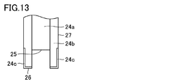
- FIG. 13 is a schematic diagram for explaining a first modification of the application member and the application needle holder according to the present embodiment.
- the first modified example of the application member and the application needle holder shown in FIG. 13 basically has the same configuration as the application member 4 and the application needle holder 20 shown in FIGS.
- the configuration of the first end 26 and the portion of the side surface connected to the first end 26 is different from the coating member and the coating needle holder 20 shown in FIGS. That is, in the outer cylinder 24b shown in FIG. 13, the lyophobic treatment portion 24c is formed on the first end 26 and the outer peripheral side surface portion 27 continuous with the first end 26.
- the lyophobic treatment section 24c is, for example, a region to which a lyophobic treatment agent is applied.
- the liquid-repellent agent for example, a fluorine-based agent can be used.
- the liquid-repellent treatment part 24c By forming the liquid-repellent treatment part 24c in this way, when forming a droplet 71 made of a liquid material at the tip 25 of the application needle 24a as shown in FIG. There is a problem that the liquid material remains on the outer peripheral side surface portion 27 and the first end 26 of the 24b and the size of the formed droplet 71 is reduced, or the shape of the droplet 71 is distorted from a spherical shape. Generation can be suppressed. For this reason, since the liquid material can be stably applied to the processing target material 5 from the tip 25 of the application needle 24a at the time of application, the possibility that the contaminated liquid material adheres to the application needle 24a after the application process can be reduced.
- FIG. 14 shows a first state in which the tip 25 of the application needle 24a is retracted inside the outer cylinder 24b from the first end 26 of the outer cylinder 24b.
- FIG. 15 shows a second state in which the tip 25 of the application needle 24a has moved from the first state to the first end 26 side of the outer cylinder 24b.
- the second modification of the coating member and the coating needle holder shown in FIGS. 14 and 15 basically has the same configuration as the coating member 4 and the coating needle holder 20 shown in FIGS.
- the configuration of the distal end of the outer cylinder 24b is different from the coating member and the coating needle holder 20 shown in FIGS. That is, in the coating member 4 and the coating needle holder 20 shown in FIGS. 14 and 15, the end of the outer cylinder 24b on the side where the first end 26 is formed is a tapered portion 24d having a tapered shape.
- the tapered portion 24d has a tapered shape such that the outer diameter increases as the distance from the first end 26 increases. Further, the thickness of the tapered portion 24d is gradually reduced toward the tip of the outer cylinder 24b.
- the tapered portion 24d has a surface extending so as to be inclined with respect to the direction in which the outer cylinder 24b extends.
- FIG. 16 and FIG. 17 are schematic diagrams for explaining a third modification of the application member and the application needle holder according to the present embodiment.
- FIG. 16 shows a first state in which the tip 25 of the application needle 24a is retracted from the first end 26 of the outer cylinder 24b into the outer cylinder 24b.
- FIG. 17 shows a second state in which the tip 25 of the application needle 24a has moved from the first state to the first end 26 side of the outer cylinder 24b.
- the second modification of the coating member and the coating needle holder shown in FIGS. 16 and 17 basically has the same configuration as the coating member 4 and the coating needle holder 20 shown in FIGS. 14 and 15,
- the configuration of the distal end of the outer cylinder 24b is different from that of the application member and the application needle holder 20 shown in FIGS. That is, in the coating member 4 and the coating needle holder 20 shown in FIGS. 16 and 17, the liquid-repellent treatment portion 24c is formed on the surface of the tapered portion 24d at the tip of the outer cylinder 24b.
- the liquid-repellent treatment part 24c extends from the tapered part 24d to a side surface of the outer cylinder 24b connected to the tapered part 24d.
- liquid-repellent portion 24c may be formed only in the tapered portion 24d.
- the effects of the application member 4 and the application needle holder 20 shown in FIGS. 14 and 15 the effects of the application member 4 and the application needle holder 20 shown in FIG.
- the supply of the liquid material to the material to be processed is performed by the coating apparatus in FIG.
- the application mechanism provided in the application device includes, for example, two application members 4 as the plurality of application members 4.
- One of the two application members 4 includes a first application needle holder.
- the other application member 4 of the two application members 4 includes a second application needle holder.
- the coating device includes the first coating needle holder and the second coating needle holder as the plurality of coating needle holders. The reason for having the first coating needle holder and the second coating needle holder is to supply a plurality of different liquid materials with a single coating device.
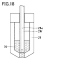
- FIG. 18 is an enlarged schematic view of the same area as the area shown in FIG. 6 in the fourth modified example of the present embodiment.
- the application needle section 24 (see FIG. 4) included in the second application needle holder has an application needle 24e and an outer cylinder 24f.
- the application needle 24e has the same configuration as the application needle 24a in FIG.
- the outer cylinder 24f has the same configuration as the outer cylinder 24b of FIG.
- the second application needle holder has the same structural features as those of the application needle holder in FIG. 6 described above.
- the second application needle holder may have the same structural features as those of any of the above-described application needle holders in FIGS.
- the second applicator needle holder has the same structural features as any of the applicator needle holders in each of the above examples of the present embodiment.
- the application needle 24e included in the application needle section 24 can supply the liquid material 70 to the processing target material by dropping the liquid material 70 from the tip of the application needle 24e.
- the application needle 24e drops the liquid material 70 in a non-contact state with the processing target material from above the processing target material, thereby supplying the liquid material 70 dropwise to the processing target material.
- the present modified example has a different feature from the above-described respective examples in which the liquid material is applied and supplied by lowering the application needle until the droplet comes in contact with the processing target material.
- the first application needle holder may also have the same structural features as any of the application needle holders of the examples of the present embodiment described above. That is, the first applicator needle holder may have the same structural features as those of the applicator needle holder of FIG. 18 or may have the same configuration as the applicator needle holder of any of FIGS. 13 to 17 described above. It may have features. Regarding the first application needle holder as well, the application needle section 24 included therein may have an application needle 24e for dropping the liquid material. Also in the fourth modified example, the features of the coating device in each of the above examples may be appropriately combined.
- FIG. 19 is a flowchart of a liquid material supply method characteristic of the fourth modification.
- the supply method PB of the liquid material characteristic of the fourth modification is roughly the same as the application method shown in FIG.
- a dropping step (S260) is performed instead of the coating step (S60) in FIG.
- FIG. 19 differs from FIG. 11 in this point.
- the supply method PB is basically the same as the application method PA in FIG.
- FIG. 20 is a schematic diagram for explaining a liquid material supply method that is characteristic of the fourth modification.
- FIG. 20A for example, the configuration shown in FIG. 18, that is, an application needle holder having an application needle 24e and an outer cylinder 24f is used.
- an application needle holder having any of the configurations shown in FIGS. 13 to 17 may be used.
- the tip 25 of the application needle 24e is retracted from the first end 26 of the outer cylinder 24f, as in FIG. 10A.
- the amount of retreat of the leading end 25 with respect to the first end 26 is larger than that in FIG. In this way, a larger amount of the liquid material 70a can be held between the first end 26 of the outer cylinder 24f and the tip 25 of the application needle 24e.
- FIG. 20A corresponds to steps (S10) to (S30) in FIG.
- FIG. 20B corresponds to the step (S40) in FIG.
- the droplet 71 may be larger than the droplet shown in FIG.
- the application needle holder is lowered again (S50).
- the droplet 71 is larger than the droplet shown in FIG.
- the droplet 71 is removed from the tip of the coating needle 24e. And fall.
- the droplet 71 is dropped on the surface of the processing target material 5 or on the liquid material 75 that has been supplied earlier to the surface.
- FIG. 20C corresponds to steps (S50) to (S260) in FIG.
- FIG. 21 is a flowchart of a coating method of a comparative example.
- the coating method is attached to a coating needle holder having an arbitrary configuration that does not have the configuration of FIG. 6 or FIGS.
- An application needle is used.
- an application needle not attached to such an application needle holder may be used.
- the application needle 124 in FIG. 9A descends toward the processing target material 5 as shown in FIG. 9B (S350).
- the liquid material 70 attached to the application needle 124 comes into contact with the surface of the processing target material 5 or the liquid material 75 previously applied to the surface. Thereby, the liquid material 70 is applied on the surface of the processing target material 5 or the surface of the liquid material 75 (S360).
- the application needle 124 is raised (S370), and the application process ends.
- FIG. 22 is a flowchart schematically showing a first example of a method for applying a liquid material in a fourth modification of the present embodiment.
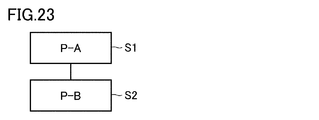
- FIG. 23 is a flowchart schematically showing a second example of the method for applying a liquid material in the fourth modification of the present embodiment.
- the coating method of the fourth modification includes a first coating step (S1) and a second coating step (S2).
- S1 a first liquid material is applied to a material to be processed.
- S2 after the first application step (S1), a second liquid material different from the first liquid material is applied to the processing target material.
- applying the liquid material to the material to be treated includes applying or dripping the liquid material so as to overlap the liquid material already supplied on the material to be treated.
- the coating method PC of the comparative example in the first coating step (S1), the coating method PC of the comparative example (see FIGS. 21 and 9) is used.
- the second coating step (S2) the supply method PB of the fourth modified example (see FIGS. 18, 19, and 20) is used.
- the coating method PA of each of the above examples see FIGS. 11 and 10) is used.
- the second application step (S2) in the second example of FIG. 23 the supply method PB of the fourth modification (see FIGS. 19 and 20) is used.
- the supply method PB using the second coating needle holder shown in FIGS. 18 to 20 is applied. That is, in the second application step (S2), the supply of the liquid material 70 or the like by dropping is performed.
- the liquid material is supplied by the application method PA using the first application needle holder having the configuration of FIG. 6 or FIGS. You may.
- the first coating step (S1) similarly to the second coating step (S2), the liquid material is supplied by the supply method PB using the coating needle holder having the configuration shown in FIGS. Is also good.
- an application needle (application needle holder) as in the comparative example of FIG. 9 is used as in the example of FIG. 22, and the application of the liquid material by the application method PC is performed. You may.
- the coating device according to the fourth modified example is a coating device including a first coating needle holder and a second coating needle holder as a plurality of coating needle holders.
- the second application needle holder has the same configuration as that of FIG. 6 and any of FIGS. 13 to 18 (for example, FIG. 18).
- the second application needle holder includes an application needle 24e capable of supplying the liquid material 70a to the processing target material 5 by dropping the liquid material 70a (see FIG. 20) as the droplet 71 from the distal end 25.
- the liquid material 75 when the liquid material 75 is already applied onto the processing target material 5 and the liquid material 70a as another material is supplied, the liquid is supplied to the application needle 24e included in the second application needle holder.
- the attachment of the material 75 is suppressed.
- the liquid material 70a is supplied by being dropped onto the liquid material 75 in a state where the liquid material 70a and the application needle 24e are not in contact with the liquid material 75.
- the first coating needle holder may have the same configuration as any of FIGS. 6 and 13 to 18 similarly to the second coating needle holder. That is, the first application needle holder may also include the application needle 24e capable of supplying the liquid material 70a to the processing target material 5 by dropping the liquid material 70a (see FIG. 20) from the tip 25, for example. With this configuration, it is also possible to suppress the contamination in the container 21 caused by the attachment of another liquid material to the application needle included in the first application needle holder.
- the application method according to the fourth modified example includes a first application step (S1) of applying the first liquid material 75 to the processing target material 5, and a coating method for the processing target material 5 after the first coating step (S1).
- a second application step (S2) of applying the second liquid material 70a In the second coating step (S2), a second coating needle holder (for example, as shown in FIG. 18) having the same configuration as that shown in FIGS. 6 and 13 to 18 is used.
- the second liquid material 70a is supplied to the processing target material 5 by dropping the second liquid material 70a from the tip 25 of the application needle 24e.
- the coating method according to the fourth modification is a coating method using a first coating needle holder and a second coating needle holder, and includes a first coating step (S1). And a second coating step (S2).
- the first application step (S1) the first liquid material 75 is applied to the processing target material 5 using the first application needle holder.
- the second application step (S2) the second liquid material 70a is applied to the processing target material 5 after the first application step (S1).
- a second coating needle holder is used.
- the second application needle holder is provided with an application needle 24e for supplying the second liquid material 70a to the processing target material 5, and a second application needle holder that surrounds the outer periphery of the application needle 24e and is located closer to the tip 25 of the application needle 24e. And an outer cylinder 24f including one end 26.
- the second liquid material 70a is supplied to the processing target material 5 by dropping the second liquid material 70a from the tip 25 of the coating needle 24e.
- the tip 25 of the coating needle 24e in the second coating needle holder is positioned inside the outer cylinder 24f from the first end 26 of the outer cylinder 24f. Holding the second liquid material 70a in the internal region of the outer cylinder 24f located between the tip 25 of the coating needle 24e and the first end 26 of the outer cylinder 24f in the first state (FIG. Step 19 (S90)) is performed.
- step (S40) in FIG. 19 A step of projecting at least a portion of the second liquid material 70a outside the first end 26 of 24f (step (S40) in FIG. 19) is performed. Further, a step (step (S260) in FIG. 19) of dropping the droplet 71, which is at least a part of the second liquid material 70a protruding outside the first end 26, onto the processing target material 5 is performed.
- the liquid material 75 when the liquid material 75 is already applied onto the processing target material 5 and the liquid material 70a as another material is supplied, the liquid is supplied to the application needle 24e included in the second application needle holder.
- the attachment of the material 75 is suppressed.
- the liquid material 70a and the application needle 24e are supplied by dropping the droplet 71 of the liquid material 70a onto the liquid material 75 in a state where the liquid material 75 is not in contact with the liquid material 75. Therefore, contamination of the container 21 due to, for example, the liquid material 75 that is a material other than the liquid material 70a originally stored in the container 21 that is the application material container can be suppressed.
- a first coating needle holder or a second coating needle holder having any one of the configurations shown in FIG. 6 or FIGS. May be used.
- the coating needle of the comparative example in FIG. 9 may be used.
- the first liquid material 75 is supplied to the processing target material 5 from the tip of the application needle.
- the application member used in the first application step (S1) can increase the degree of freedom of selection.
- the number of application members 4 included in the application device in FIG. 1 is not limited to two, and may be three or more.
- all but one of the plurality of three or more coating members 4 include, as a second coating needle holder, a coating needle having, for example, a configuration as shown in FIG.
- the material is supplied.
- the other one may have, for example, a configuration as shown in FIG. 18 as the first application needle holder, or a configuration having any of the configurations shown in FIGS. 6, 13 to 17. Is also good.
- the application needle of the first application needle holder may have the configuration of the comparative example in FIG.
- the first liquid material 75 is supplied to the processing target material 5 from the tip of the application needle by the application needle of the first application needle holder (see FIG. 20). Thereafter, that is, in the second step and thereafter (including the third step, the fourth step, and the like), the second application needle holder is used.
- the liquid material 72 is supplied to the processing target material 5 by dropping the liquid material 70a as the droplet 71 from the tip end 25 of the application needle 24e as in the dropping process PB in FIGS. 19 and 20.
- the second application needle holder preferably includes the application needle 24e to which the droplet 71 can be dropped.
Landscapes
- Coating Apparatus (AREA)
- Application Of Or Painting With Fluid Materials (AREA)
Abstract
L'invention concerne un support d'aiguille de revêtement, un élément de revêtement, un dispositif de revêtement et un procédé de revêtement, l'application d'un revêtement ou une autre alimentation d'un matériau liquide pouvant être réalisée de manière stable à l'aide d'une aiguille de revêtement. Un support d'aiguille de revêtement (20) est pourvu d'une aiguille de revêtement (24a) permettant de fournir du liquide à un élément objet de traitement (5), d'un cylindre externe (24b) et d'une première unité d'entraînement (80). Le cylindre externe (24b) entoure la périphérie externe de l'aiguille de revêtement (24a) et comprend une première extrémité (26) positionnée sur le côté proche de l'extrémité distale (25) de l'aiguille de revêtement (24a). La première unité d'entraînement (80) amène le cylindre externe (24b) à se déplacer par rapport à l'aiguille de revêtement (24a) dans une première direction qui est la direction dans laquelle s'étend l'aiguille de revêtement (24a). La première unité d'entraînement (80) est conçue de façon à commuter entre un premier état dans lequel l'extrémité distale (25) de l'aiguille de revêtement (24a) est rétractée dans le cylindre externe (24b) à partir de la première extrémité (26) du cylindre externe (24b), et un second état dans lequel l'extrémité distale (25) de l'aiguille de revêtement (24a) est davantage déplacée vers la première extrémité (26) du cylindre externe (24b) que dans le premier état.
Applications Claiming Priority (6)
| Application Number | Priority Date | Filing Date | Title |
|---|---|---|---|
| JP2018140594A JP7050611B2 (ja) | 2018-07-26 | 2018-07-26 | 塗布部材、塗布装置および塗布方法 |
| JP2018-140594 | 2018-07-26 | ||
| JP2018-140595 | 2018-07-26 | ||
| JP2018140595 | 2018-07-26 | ||
| JP2019124560A JP7391554B2 (ja) | 2018-07-26 | 2019-07-03 | 塗布装置および塗布方法 |
| JP2019-124560 | 2019-07-03 |
Publications (1)
| Publication Number | Publication Date |
|---|---|
| WO2020022449A1 true WO2020022449A1 (fr) | 2020-01-30 |
Family
ID=69181758
Family Applications (1)
| Application Number | Title | Priority Date | Filing Date |
|---|---|---|---|
| PCT/JP2019/029268 Ceased WO2020022449A1 (fr) | 2018-07-26 | 2019-07-25 | Support d'aiguille de revêtement, élément de revêtement, dispositif de revêtement et procédé de revêtement |
Country Status (1)
| Country | Link |
|---|---|
| WO (1) | WO2020022449A1 (fr) |
Citations (6)
| Publication number | Priority date | Publication date | Assignee | Title |
|---|---|---|---|---|
| JP2002323509A (ja) * | 2001-04-26 | 2002-11-08 | Thk Co Ltd | マイクロアレイ作製用ヘッド、このヘッドを用いたマイクロアレイ作製装置、マイクロアレイ作製方法、及びマイクロアレイ |
| US20040140371A1 (en) * | 2003-01-16 | 2004-07-22 | Engel Harold J. | Nozzle end configuration |
| JP2006310266A (ja) * | 2005-03-28 | 2006-11-09 | Ntn Corp | 塗布ユニットおよびパターン修正装置 |
| JP2008191091A (ja) * | 2007-02-07 | 2008-08-21 | Univ Of Electro-Communications | 液滴塗布装置 |
| JP2013013865A (ja) * | 2011-07-05 | 2013-01-24 | Ntn Corp | 液体塗布機構、液体塗布装置および液体塗布方法 |
| WO2016117455A1 (fr) * | 2015-01-21 | 2016-07-28 | 日本電子精機株式会社 | Dispositif et procédé d'application de revêtement, et unité d'application de revêtement |
-
2019
- 2019-07-25 WO PCT/JP2019/029268 patent/WO2020022449A1/fr not_active Ceased
Patent Citations (6)
| Publication number | Priority date | Publication date | Assignee | Title |
|---|---|---|---|---|
| JP2002323509A (ja) * | 2001-04-26 | 2002-11-08 | Thk Co Ltd | マイクロアレイ作製用ヘッド、このヘッドを用いたマイクロアレイ作製装置、マイクロアレイ作製方法、及びマイクロアレイ |
| US20040140371A1 (en) * | 2003-01-16 | 2004-07-22 | Engel Harold J. | Nozzle end configuration |
| JP2006310266A (ja) * | 2005-03-28 | 2006-11-09 | Ntn Corp | 塗布ユニットおよびパターン修正装置 |
| JP2008191091A (ja) * | 2007-02-07 | 2008-08-21 | Univ Of Electro-Communications | 液滴塗布装置 |
| JP2013013865A (ja) * | 2011-07-05 | 2013-01-24 | Ntn Corp | 液体塗布機構、液体塗布装置および液体塗布方法 |
| WO2016117455A1 (fr) * | 2015-01-21 | 2016-07-28 | 日本電子精機株式会社 | Dispositif et procédé d'application de revêtement, et unité d'application de revêtement |
Similar Documents
| Publication | Publication Date | Title |
|---|---|---|
| JP6787620B2 (ja) | 電子部品の製造装置 | |
| WO2017090381A1 (fr) | Unité de revêtement, dispositif de revêtement, procédé de production d'un objet à revêtir et procédé de production d'un substrat | |
| JP2017000947A (ja) | 塗布ユニットおよびそれを用いた塗布装置 | |
| JP6381902B2 (ja) | 塗布針ホルダ | |
| WO2010018675A1 (fr) | Dispositif et procédé de déversement de liquide | |
| JP7050611B2 (ja) | 塗布部材、塗布装置および塗布方法 | |
| JP7391554B2 (ja) | 塗布装置および塗布方法 | |
| WO2020022449A1 (fr) | Support d'aiguille de revêtement, élément de revêtement, dispositif de revêtement et procédé de revêtement | |
| JP2012124381A (ja) | 塗布装置、塗布方法、およびパターン修正装置 | |
| JP2010087320A (ja) | ペースト塗布装置およびペースト塗布方法 | |
| JP7535965B2 (ja) | 液体材料塗布ユニット、液体材料塗布装置および液体材料塗布方法 | |
| JP6560108B2 (ja) | 塗布ユニット、塗布装置、被塗布対象物の製造方法および基板の製造方法 | |
| JP2006289295A (ja) | 粘性材料塗布装置、及び粘性材料塗布方法 | |
| JP2019025450A (ja) | 塗布機構及び塗布装置 | |
| CN113474088B (zh) | 液体涂布单元和液体涂布装置 | |
| US20230083367A1 (en) | Liquid material application unit, liquid material application device, and liquid material application method | |
| CN118321094A (zh) | 涂胶装置、涂胶控制方法、装置、设备、介质及程序产品 | |
| JP6587945B2 (ja) | 塗布機構、塗布装置、被塗布対象物の製造方法、および基板の製造方法 | |
| JP2018034105A (ja) | 液体塗布ユニット、液体塗布装置および液体塗布方法 | |
| JP6830330B2 (ja) | 液体塗布ユニット、液体塗布装置、および液体塗布方法 | |
| JP2011120968A (ja) | ペースト供給装置及びペースト供給方法 | |
| JP2017094287A (ja) | 塗布ユニット、塗布装置、被塗布対象物の製造方法および基板の製造方法 | |
| WO2018043537A1 (fr) | Unité de revêtement liquide et dispositif de revêtement liquide | |
| JP2018034124A (ja) | 液体塗布ユニットおよび液体塗布装置 | |
| JP2009279524A (ja) | ディスペンサ装置、及びディスペンサ装置の制御方法 |
Legal Events
| Date | Code | Title | Description |
|---|---|---|---|
| 121 | Ep: the epo has been informed by wipo that ep was designated in this application |
Ref document number: 19840204 Country of ref document: EP Kind code of ref document: A1 |
|
| NENP | Non-entry into the national phase |
Ref country code: DE |
|
| 122 | Ep: pct application non-entry in european phase |
Ref document number: 19840204 Country of ref document: EP Kind code of ref document: A1 |