WO2020026452A1 - Dispositif de gestion d'équipement, système de gestion d'équipement, procédé de gestion d'équipement, et programme - Google Patents
Dispositif de gestion d'équipement, système de gestion d'équipement, procédé de gestion d'équipement, et programme Download PDFInfo
- Publication number
- WO2020026452A1 WO2020026452A1 PCT/JP2018/029307 JP2018029307W WO2020026452A1 WO 2020026452 A1 WO2020026452 A1 WO 2020026452A1 JP 2018029307 W JP2018029307 W JP 2018029307W WO 2020026452 A1 WO2020026452 A1 WO 2020026452A1
- Authority
- WO
- WIPO (PCT)
- Prior art keywords
- unit
- equipment management
- equipment
- external unit
- information
- Prior art date
- Legal status (The legal status is an assumption and is not a legal conclusion. Google has not performed a legal analysis and makes no representation as to the accuracy of the status listed.)
- Ceased
Links
Images




Classifications
-
- G—PHYSICS
- G06—COMPUTING OR CALCULATING; COUNTING
- G06F—ELECTRIC DIGITAL DATA PROCESSING
- G06F13/00—Interconnection of, or transfer of information or other signals between, memories, input/output devices or central processing units
Definitions
- an equipment management apparatus that controls equipment and monitors the state of the equipment.
- the functions required for the equipment management device differ depending on the management purpose, budget, and the like.
- a display function for displaying the state of the equipment may be required of the equipment management apparatus, or such a display function may not be required of the equipment management apparatus. For this reason, it is desirable to provide the equipment management apparatus with a minimum function and add the function to the equipment management apparatus according to the user's request.
- Patent Literature 1 discloses a technique of dividing a panel computer into a display module and a main module to improve maintainability.
- the display module and the main module are electrically connected by a connector that is inserted and removed in conjunction with the attachment / detachment operation between the display module and the main module.
- the equipment management device An equipment management device for managing equipment, Device-side communication means for transmitting control information indicating the control content of the equipment to the equipment, and receiving state information indicating the state of the equipment from the equipment,
- an external unit for adding a function to the equipment management device is mounted on the equipment management device, the external unit wirelessly communicates with the external unit, and performs wireless communication between the equipment management device and the external unit.
- a unit-side communication means for establishing a connection;
- Storage means for storing software for adding the function to the equipment management device by the external unit, Executing the software and using the wireless communication connection, at least one of a process of acquiring information on the control information from the external unit and a process of transmitting information on the state information to the external unit.
- a processing executing means for executing the processing of (1).
- the external unit when the external unit is mounted on the equipment management device, a wireless communication connection between the equipment management device and the external unit is established, and the information on the control information is externally transmitted using the wireless communication connection. At least one of a process of acquiring from the unit and a process of transmitting information on the state information to the external unit is executed. Therefore, according to the present invention, a function can be easily added to the equipment management apparatus.
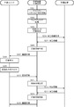
- FIG. 6 is a sequence diagram showing a procedure of processing for each unit according to the first embodiment of the present invention.
- Functional configuration diagram of an equipment management apparatus according to a second embodiment of the present invention Functional configuration diagram of an external unit according to Embodiment 2 of the present invention
- FIG. 9 is a sequence diagram showing a procedure of processing for each unit according to the second embodiment of the present invention.
- the equipment management system 1000 is a system that manages at least one equipment 300.
- Managing the equipment 300 is a concept that includes, for example, monitoring the state of the equipment 300 and controlling the equipment 300.
- the state of the equipment 300 is an operation state of the equipment 300.
- the equipment management system 1000 includes an equipment management apparatus 100, an external unit 200, a monitoring terminal 400, a remote server 500, and a remote server 510.
- the equipment management apparatus 100 and the external unit 200 are essential components
- the monitoring terminal 400, the remote server 500, and the remote server 510 are not essential components.
- the extended function is an additional function to be held as necessary among functions related to the management of the equipment 300.
- the extension function is a function that can be realized by the cooperation between the equipment management apparatus 100 and the external unit 200.
- a display function, an operation function, a remote management function, an operation history recording function, or a device interlocking function is used. is there.
- the display function is a function for displaying a screen indicating the state of the equipment 300.
- the operation function is a function of receiving an operation on the equipment 300 and controlling the equipment 300.
- the remote management function is a function of controlling and managing the equipment 300 remotely.
- the operation history recording function is a function of recording the operation history of the equipment 300.
- the device linking function is a function for linking the facility device 300 with another device (not shown).
- the extended functions are a display function and an operation function.
- the equipment management apparatus 100 downloads the plug-in software held by the external unit 200 and executes the downloaded plug-in software. I do. Therefore, the equipment management apparatus 100 does not need to hold the plug-in software in advance. Therefore, for example, when a new external unit 200 is developed, there is no need to change the equipment management apparatus 100. Therefore, a reduction in the cost of adding a function to the equipment management apparatus 100 can be expected.
- the plug-in software is software that is installed in the equipment management apparatus 100 in order to use the extended function corresponding to the external unit 200.
- the communication network 610 is a communication network for interconnecting the equipment management apparatus 100 and at least one equipment 300, and is, for example, a wired communication network including a dedicated communication line.
- the communication network 610 transmits not only information but also power. That is, the equipment management apparatus 100 receives power supply from at least one equipment 300 via the communication network 610.
- the equipment management apparatus 100 includes a processor 11, a flash memory 12, a button 13, a first communication interface 14, a second communication interface 15, a third communication interface 16, A communication interface 17.
- the processor 11 controls the entire operation of the equipment management apparatus 100.
- the processor 11 is, for example, a CPU (Central Processing Unit) incorporating a ROM (Read Only Memory), a RAM (Random Access Memory), an RTC (Real Time Clock), and the like.
- the CPU operates according to a basic program stored in a ROM, for example, and uses a RAM as a work area.
- the flash memory 12 is a nonvolatile memory for storing various information.
- the flash memory 12 stores, for example, a program executed by the processor 11.
- the button 13 detects an operation performed by the user, and supplies a signal indicating a result of the detection to the processor 11.
- the first communication interface 14 is a communication interface for connecting the equipment management apparatus 100 to the communication network 610.
- the first communication interface 14 is a communication interface for connecting to a dedicated communication line for transmitting information and power.
- the second communication interface 15 is a communication interface for connecting the equipment management apparatus 100 to the communication network 620.
- the second communication interface 15 is a communication interface compatible with NFC.
- the third communication interface 16 is a communication interface for connecting the equipment management apparatus 100 to the communication network 630.
- the third communication interface 16 is a communication interface compatible with Bluetooth (registered trademark).
- the fourth communication interface 17 is a communication interface for connecting the equipment management apparatus 100 to the communication network 640.
- the fourth communication interface 17 is a communication interface compatible with Wi-Fi.
- the external unit 200 is a device for adding an extended function to the equipment management device 100.
- the external unit 200 is a device for adding a display function and an operation function to the equipment management apparatus 100. That is, the external unit 200 is a device that displays a state of the equipment 300 and displays a monitoring operation screen for accepting an operation on the equipment 300.
- the external unit 200 includes a processor 21, a flash memory 22, a touch screen 23, a first communication interface 24, a second communication interface 25, and a third communication interface 26.
- the processor 21 controls the entire operation of the external unit 200.
- the processor 21 is, for example, a CPU including a ROM, a RAM, an RTC, and the like.
- the CPU operates according to a basic program stored in a ROM, for example, and uses a RAM as a work area.
- the flash memory 22 is a non-volatile memory that stores various information.
- the flash memory 22 stores, for example, a program executed by the processor 21.
- the touch screen 23 detects an operation performed by the user, and supplies a signal indicating a result of the detection to the processor 21.
- the touch screen 23 displays information according to the control of the processor 21.
- the first communication interface 24 is a communication interface for connecting the external unit 200 to the communication network 620.
- the first communication interface 24 is a communication interface compatible with NFC.
- the second communication interface 25 is a communication interface for connecting the external unit 200 to the communication network 630.
- the second communication interface 25 is a communication interface compatible with Bluetooth (registered trademark).
- the third communication interface 26 is a communication interface for connecting the external unit 200 to the communication network 650.
- the third communication interface 26 is a communication interface compatible with Wi-Fi.
- the role of the monitoring terminal 400 is similar to that of the external unit 200 in the present embodiment in that a display function and an operation function are added to the equipment management apparatus 100. However, the external unit 200 is used when the display function and the operation function are used at all times, and the monitoring terminal 400 is used when the display function and the operation function are used temporarily. The role and the role of the monitoring terminal 400 are different.
- the monitoring terminal 400 is different from the external unit 200 in that the monitoring terminal 400 has a built-in web browser and generates screen information.
- the monitoring terminal 400 is, for example, a smartphone, a notebook computer, or a tablet terminal.
- the remote server 500 and the remote server 510 are servers that remotely manage the equipment 300.
- the remote server 500 or the remote server 510 is connected to the external unit 200 via the communication network 650. Which of the remote server 500 and the remote server 510 is connected to the external unit 200 depends on the type of the external unit 200.
- the remote server 500 and the remote server 510 are, for example, servers that manage the equipment information 1051, analyze energy saving, failure prediction, maintenance time prediction, and the like based on the equipment information 1051, and execute various controls. .
- the equipment management device 100 functionally includes a device communication unit 101, a unit communication unit 102, a terminal communication unit 103, a control unit 104, and a data management unit 105.
- a power supply unit 106 The device-side communication unit corresponds to, for example, the device-side communication unit 101.
- the unit-side communication unit corresponds to, for example, the unit-side communication unit 102.
- the processing execution unit included in the equipment management apparatus 100 corresponds to, for example, the control unit 104.
- the storage unit corresponds to, for example, the data management unit 105.
- the power supply unit corresponds to, for example, the power supply unit 106.
- the device-side communication unit 101 transmits control information indicating the control content of the device 300 to the device 300. Further, the device-side communication unit 101 receives status information indicating the status of the facility device 300 from the facility device 300.
- the function of the device-side communication unit 101 is realized by, for example, cooperation between the processor 11 and the first communication interface 14.
- the unit-side communication unit 102 wirelessly communicates with the external unit 200 when the external unit 200 for adding a function to the equipment management apparatus 100 is mounted on the equipment management apparatus 100. Then, the unit-side communication unit 102 establishes a wireless communication connection between the equipment management apparatus 100 and the external unit 200.
- the function of the unit-side communication unit 102 is realized, for example, by the cooperation of the processor 11, the second communication interface 15, and the third communication interface 16.
- the terminal side communication unit 103 communicates with the monitoring terminal 400.
- the terminal-side communication unit 103 transmits the status information received by the device-side communication unit 101 from the facility device 300 to the monitoring terminal 400. Further, the terminal-side communication unit 103 receives control information from the monitoring terminal 400.
- the function of the terminal-side communication unit 103 is realized by, for example, cooperation between the processor 11 and the fourth communication interface 17.
- the data management unit 105 stores software for adding the above functions to the equipment management apparatus 100 by the external unit 200.
- This software is basically plug-in software.
- the function of the data management unit 105 is realized by, for example, cooperation between the processor 11 and the flash memory 12.
- the control unit 104 executes software.
- the control unit 104 executes at least one of an information acquisition process and an information transmission process using a wireless communication connection.
- the information acquisition process is a process of acquiring information related to control information from the external unit 200.
- the information transmission process is a process of transmitting information related to state information to the external unit 200.
- the function of the control unit 104 is realized, for example, by the processor 11 executing a program stored in the flash memory 12.
- the unit-side communication unit 102 downloads software from the external unit 200. Then, the data management unit 105 stores the software downloaded by the unit-side communication unit 102.
- the unit-side communication unit 102 changes the version of the second plug-in software to the first plug-in software. If it is newer than the software version, the second plug-in software is downloaded from the external unit 200. Both the first plug-in software and the second plug-in software are plug-in software.
- the data management unit 105 stores the second plug-in software instead of the first plug-in software.
- the unit-side communication unit 102 includes a first communication unit 1021 and a second communication unit 1022.
- the first communication unit 1021 establishes the connection of the wireless communication by the first wireless communication having the first communication speed.
- the second communication unit 1022 wirelessly communicates with the external unit 200 by the second wireless communication having the second communication speed higher than the first communication speed.
- the first communication unit included in the equipment management apparatus 100 corresponds to, for example, the first communication unit 1021.
- the second communication unit included in the equipment management apparatus 100 corresponds to, for example, the second communication unit 1022.
- the function of the first communication unit 1021 is realized by, for example, cooperation between the processor 11 and the second communication interface 15.
- the function of the second communication unit 1022 is realized by, for example, cooperation between the processor 11 and the third communication interface 16.
- the power supply unit 106 supplies power to the external unit 200 in a non-contact manner.
- the function of the power supply unit 106 is realized, for example, by cooperation of an AC power supply (not shown) and a coil (not shown). That is, when the coil included in power supply unit 106 and the coil included in power reception unit 206 are combined to form a transformer, power is supplied from power supply unit 106 to power reception unit 206 in a non-contact manner.
- the external unit 200 is a screen display unit that displays a state of the equipment 300 and displays a monitoring operation screen for receiving designation of control content for the equipment 300. Therefore, the control unit 104 generates a monitoring operation screen based on the status information received by the device-side communication unit 101. On the other hand, the unit-side communication unit 102 transmits screen information indicating the monitoring operation screen generated by the control unit 104 to the external unit 200.
- the control unit 104 when the external unit 200 is the first screen display unit, the control unit 104 generates a first monitoring operation screen associated with the first screen display unit.
- the external unit 200 is a second screen display unit different from the first screen display unit, a second monitoring operation screen different from the first monitoring operation screen associated with the second screen display unit is generated.
- the first screen display unit and the second screen display unit are screen display units having different screen sizes, screen shapes, light emitting element types, or display update speeds, for example. For example, when the screen display unit has a large screen, the control unit 104 generates a screen with many display items, and when the screen display unit has a small screen, generates a screen with few display items.
- the control unit 104 controls the operation of the entire equipment management apparatus 100.
- the control unit 104 includes an equipment management unit 1041, a wireless connection management unit 1042, an external unit identification unit 1043, an external unit access unit 1044, and a web browser execution unit 1045.
- the equipment management unit 1041 manages the operation state of the equipment 300 connected to the equipment management apparatus 100.
- the wireless connection management unit 1042 automatically establishes a wireless communication connection between the unit-side communication unit 102 and the management device-side communication unit 203 when the external unit 200 is mounted on the equipment management device 100.
- the external unit identification unit 1043 identifies the type of the external unit 200. This type is, for example, a type for distinguishing whether the external unit 200 is a screen display unit or a server connection unit.
- the external unit access unit 1044 transmits necessary data to the external unit 200 and receives necessary data from the external unit 200.
- the web browser execution unit 1045 executes a web browser and generates screen information indicating a monitoring operation screen.
- the data management unit 105 manages data necessary for managing the equipment 300 and data required for communication with the external unit 200.
- the data management unit 105 stores and manages equipment device information 1051, web content 1052, external unit information 1053, external unit software 1054, and external unit specific information 1055.
- the equipment information 1051 and the web content 1052 are basically information stored in the equipment management apparatus 100 before the external unit 200 is mounted on the equipment management apparatus 100.
- the external unit information 1053, the external unit software 1054, and the external unit specific information 1055 are appropriately copied from the external unit 200 to the equipment management apparatus 100 when the external unit 200 is mounted on the equipment management apparatus 100. Information.
- the equipment information 1051 is information on the equipment 300 connected to the equipment management apparatus 100.
- the equipment information 1051 is, for example, information indicating an operation state and model data.
- the operating state is the current operating state of the equipment 300, for example, an operating state indicating one of operating and stopped, an operating mode indicating one of cooling, heating, dehumidifying, and blowing, a set temperature, Alternatively, the room temperature is included.
- the operating state is updated to the latest state at any time by communication between the equipment management apparatus 100 and the external unit 200.
- the model data is data on the model of the equipment 300.
- the model data includes the model of the facility device 300, the serial number of the facility device 300, the model name of the facility device 300, or a data list held by the facility device 300.
- the web content 1052 is data for displaying a monitoring operation screen on the external unit 200 or the monitoring terminal 400.
- the web contents 1052 include, for example, HTML (Hyper Text Markup Language) contents and a screen program.
- HTML content includes a screen layout configuration file and an image file.
- the screen layout configuration file is, for example, an HTML file that describes a frame configuration.
- the image file is, for example, a file described in a GIF (Graphics Interchange Format) format, a JPEG (Joint Photographic Experts Group) format file, or a file described in a BMP (Bitmap) format.
- the screen program is a program that can be executed on a web browser.
- the screen program is, for example, a program described in JavaScript (registered trademark) operable on a web browser.
- the screen program is a program that can dynamically generate a screen.
- the screen program can display the equipment 300 by, for example, an icon or a list, and can display the equipment 300 while changing the operation state or the abnormal state of the equipment 300.
- the external unit information 1053 is information relating to the external unit 200 attached to the equipment management apparatus 100, and is information for correctly operating the external unit 200.
- the external unit information 1053 includes a unit type and a plug-in software version.
- the unit type is information for identifying the type of the external unit 200.
- the unit type is, for example, a type for distinguishing whether the external unit 200 is a screen display unit or a server connection unit.
- the plug-in software version is, for example, a number indicating the version of the plug-in software held by the data management unit 105.
- the external unit software 1054 is a program that enables communication between the equipment management apparatus 100 and the external unit 200 and control of the external unit 200.
- the external unit software 1054 includes plug-in software.
- the plug-in software is an auxiliary application that is additionally installed in the equipment management apparatus 100 in order to extend the functions of the application provided in the equipment management apparatus 100. That is, the plug-in software is a program downloaded from the external unit 200 to the equipment management apparatus 100 and executed by the equipment management apparatus 100.
- the plug-in software is a program that defines processing for realizing an extended function corresponding to the external unit 200.
- the plug-in software is, for example, a program that collects information required by the external unit 200 from the equipment 300, converts the collected information into a format suitable for the external unit 200, and transmits the converted information to the external unit 200. is there.
- the converted information is, for example, image information or maintenance information.
- the external unit unique information 1055 is information unique to the type of the external unit 200.
- the external unit unique information 1055 includes a screen acquisition URL.
- the screen acquisition URL is a URL for specifying a top page of a browser screen to be displayed on the external unit 200 which is a screen display unit.
- the browser screen is a monitoring operation screen or a setting screen.
- the URL of the web content 1052 for generating a large screen is a first URL
- the URL of the web content 1052 for generating a small screen is a second URL
- the first URL is the screen acquisition URL included in the external unit unique information 2053 held by the external unit 200 having the large screen
- the screen acquisition URL included in the external unit unique information 2053 held by the external unit 200 having the small screen is the first URL. 2 URL.
- an appropriate screen according to the size of the screen of the external unit 200 is generated and displayed.
- the screen acquisition URL is a URL corresponding to, for example, the size of the screen, the shape of the screen, the type of the light emitting element, or the display update speed.
- the external unit 200 functionally includes a display unit 201, an operation receiving unit 202, a management device communication unit 203, a control unit 204, a data management unit 205, and a power receiving unit 206.
- the management device side communication unit corresponds to, for example, the management device side communication unit 203.
- the processing execution means included in the external unit 200 corresponds to, for example, the control unit 204.
- the power receiving unit corresponds to, for example, the power receiving unit 206.
- the operation receiving unit 202 receives an operation performed by a user.
- the operation by the user is, for example, an operation for instructing control of the facility device 300 or an operation for instructing switching of the browser screen.
- the operation receiving unit 202 supplies operation information indicating the content of the operation to the control unit 204.
- the operation information is, for example, information indicating coordinates on the browser screen specified by the user.
- the function of the operation receiving unit 202 is realized by, for example, cooperation between the processor 21 and the touch screen 23.
- the management device communication unit 203 When the external unit 200 is mounted on the equipment management device 100, the management device communication unit 203 performs wireless communication with the equipment management device 100. Then, the management device-side communication unit 203 establishes a wireless communication connection between the equipment management device 100 and the external unit 200.
- the function of the management device-side communication unit 203 is realized by, for example, cooperation between the processor 21, the first communication interface 24, and the second communication interface 25.
- the control unit 204 performs at least one of an information transmission process and an information acquisition process using a wireless communication connection.
- the information transmission process is a process of transmitting information related to control information to the equipment management apparatus 100.
- the information acquisition process is a process of acquiring information related to state information from the equipment management apparatus 100.
- the function of the control unit 204 is realized, for example, by the processor 21 executing a program stored in the flash memory 22.
- the management device-side communication unit 203 includes a first communication unit 2031 and a second communication unit 2032.
- the first communication unit 2031 establishes a wireless communication connection by the first wireless communication.
- the second communication unit 2032 wirelessly communicates with the equipment management apparatus 100 by the second wireless communication.
- the first communication unit included in the external unit 200 corresponds to, for example, the first communication unit 2031.
- the second communication unit included in the external unit 200 corresponds to, for example, the second communication unit 2032.
- the function of the first communication unit 2031 is realized by, for example, cooperation between the processor 21 and the first communication interface 24.
- the function of the second communication unit 2032 is realized by, for example, cooperation between the processor 21 and the second communication interface 25.
- the data management unit 205 stores plug-in software for adding the above functions to the equipment management apparatus 100 by the external unit 200.
- the function of the data management unit 205 is realized by, for example, cooperation between the processor 21 and the flash memory 22.
- the power receiving unit 206 receives power from the equipment management apparatus 100 in a non-contact manner.
- the external unit 200 operates with the power received by the power receiving unit 206.
- the function of the power receiving unit 206 is realized, for example, by cooperation of a storage battery (not shown) and a coil (not shown).
- the data management unit 205 manages data for operating the external unit 200 normally.
- the data management unit 205 stores and manages external unit information 2051, external unit software 2052, and external unit specific information 2053.
- the external unit information 2051, the external unit software 2052, and the external unit specific information 2053 are information that is appropriately copied from the external unit 200 to the equipment management apparatus 100 when the external unit 200 is mounted on the equipment management apparatus 100. It is.
- the power supply unit 106 When the external unit 200 is attached to the equipment management apparatus 100, the power supply unit 106 performs non-contact power supply to the power receiving unit 206, and the first wireless communication between the first communication unit 1021 and the first communication unit 2031 is performed. It becomes possible. Then, when the connection of the wireless communication is established by the first wireless communication, the second wireless communication between the second communication unit 1022 and the second communication unit 2032 becomes possible.
- the first wireless communication is basically a wireless communication by NFC.
- the equipment management apparatus 100 requests pairing information from the external unit 200 (step S101). That is, the first communication unit 1021 transmits request information requesting pairing information to the first communication unit 2031.
- the external unit 200 transmits the pairing information to the equipment management apparatus 100 (Step S102). That is, the first communication unit 2031 transmits the pairing information to the first communication unit 1021.
- the pairing information is information necessary for pairing of the second wireless communication, and is, for example, address information indicating an address of the external unit 200.
- the second wireless communication is basically a wireless communication using Bluetooth (registered trademark).
- the equipment management apparatus 100 automatically performs the pairing (step S103).
- this pairing wireless communication by the second wireless communication between the equipment management apparatus 100 and the external unit 200 becomes possible.
- the connection of the wireless communication is attempted by the first wireless communication in which the power consumption is small, the communication speed is low, and the connection of the wireless communication is easily established.
- the wireless communication by the second wireless communication which consumes a large amount of power, has a high communication speed, and cannot easily establish the connection of the wireless communication is executed.
- an external unit 200 other than the external unit 200 mounted on the equipment management apparatus 100 may be arranged at a position where communication with the equipment management apparatus 100 by the first wireless communication is possible. Even in this case, the other external units 200 cannot receive power from the equipment management apparatus 100 because they are not attached to the equipment management apparatus 100. For this reason, it is considered that the wireless communication connection between the equipment management apparatus 100 and the other external unit 200 is not established.
- the equipment management apparatus 100 requests unit type information from the external unit 200 (step S104). That is, the second communication unit 1022 transmits request information requesting unit type information to the second communication unit 2032.
- the external unit 200 transmits unit type information to the equipment management apparatus 100 (step S105). That is, the second communication unit 2032 reads the unit type included in the external unit information 2051 stored by the data management unit 205 as unit type information, and transmits the unit type information to the second communication unit 1022.
- the equipment management apparatus 100 stores the received unit type information (step S106). Specifically, the control unit 104 causes the data management unit 105 to store the external unit information 1053 including the unit type information received by the second communication unit 1022.
- the equipment management apparatus 100 requests version information from the external unit 200 (step S107). That is, the second communication unit 1022 transmits request information for requesting the version information to the second communication unit 2032.
- the external unit 200 transmits the version information to the equipment management apparatus 100 (Step S108). That is, the second communication unit 2032 reads the plug-in software version included in the external unit information 2051 stored in the data management unit 205 as version information, and transmits the plug-in software version to the second communication unit 1022.
- the equipment management apparatus 100 stores the received version information (step S109). Specifically, control unit 104 temporarily stores the version information received by second communication unit 1022.
- the external unit 200 reads the plug-in software (Step S112), and transmits the plug-in software to the equipment management apparatus 100 (Step S113). That is, the second communication unit 2032 reads plug-in software included in the external unit software 2052 stored in the data management unit 205 and transmits the plug-in software to the second communication unit 1022.
- the equipment management apparatus 100 writes the received plug-in software (step S114). Specifically, the control unit 104 causes the data management unit 105 to store the external unit software 1054 including the plug-in software received by the second communication unit 1022.
- the plug-in software is appropriately incorporated into the basic software included in the equipment management apparatus 100, and is installed in the equipment management apparatus 100.
- step S110 When determining that the version of the plug-in software held is the latest version (step S110: YES), or when the processing of step S114 is completed, the equipment management apparatus 100 Request unique information (step S115). That is, the second communication unit 1022 transmits request information for requesting the unique information to the second communication unit 2032.
- the external unit 200 reads the unique information (Step S116), and transmits the unique information to the equipment management apparatus 100 (Step S117). That is, the second communication unit 2032 reads the external unit unique information 2053 stored by the data management unit 205 and transmits the information to the second communication unit 1022.
- the equipment management apparatus 100 writes the received unique information (step S118). Specifically, the control unit 104 causes the data management unit 105 to store the external unit unique information 1055 including the unique information received by the second communication unit 1022.
- the external unit 200 which is a screen display unit, displays a monitoring operation screen based on image information received from the equipment management apparatus 100.
- the equipment management apparatus 100 starts executing the plug-in software (step S201). Specifically, the control unit 104 executes plug-in software included in the external unit software 1054 stored in the data management unit 105.
- the equipment management apparatus 100 starts a web browser (step S202), and acquires a screen of the designated URL (step S203). Specifically, the control unit 104 acquires, from the data management unit 105, the web content 1052 indicated by the screen acquisition URL included in the external unit unique information 1055 stored in the data management unit 105.
- the equipment management apparatus 100 transmits the screen information to the external unit 200 (step S207).
- the external unit 200 displays a screen based on the screen information (Step S208).
- the external unit 200 receives a screen operation from the user (Step S209).
- the external unit 200 transmits coordinate information indicating the operation position on the screen to the equipment management apparatus 100 (step S210).
- the external unit 200 when the external unit 200 is mounted on the equipment management apparatus 100, a wireless communication connection between the equipment management apparatus 100 and the external unit 200 is established, and wireless communication is established. At least one of a process of acquiring information on control information from the external unit 200 and a process of transmitting information on status information to the external unit 200 using the connection is executed. Therefore, according to the present embodiment, it is possible to easily add a function to the equipment management apparatus 100.
- the equipment management device 100 functionally includes a device communication unit 101, a unit communication unit 102, a terminal communication unit 103, a control unit 104, and a data management unit 105. , A power supply unit 106.
- the control unit 104 does not include the web browser execution unit 1045.
- the external unit unique information 1055 does not include the screen acquisition URL, but includes the collection data type, the collection cycle, and the connection destination remote server.
- the collected data type is the type of data collected by the remote server 500 or 510.
- the collection cycle is a cycle at which the remote server 500 or 510 collects data.
- the connection destination remote server is the remote server 500 or the remote server 510 to which the external unit 200 is connected. In FIG. 9, information provided in the external unit information 1053 and the external unit software 1054 is omitted.
- the communication card storage unit 207 stores a communication card (not shown) used for connection to the communication network 650 by the server-side communication unit 208.
- This communication card is, for example, a SIM (Subscriber Identify Module) card when the communication network 650 includes a mobile phone communication network.
- the server-side communication unit 208 connects the external unit 200 to the communication network 650. That is, the server-side communication unit 208 communicates with the remote server 500 or the remote server 510 via the communication network 650.
- the function of the server-side communication unit 208 is realized by, for example, cooperation between the processor 21 and the third communication interface 26.
- the wide area communication control unit 2045 controls the wide area communication by the server communication unit 208.
- the external unit 200 which is a server connection unit
- the remote server 500 is connected to the remote server 500 so that the remote server 500 can monitor and control the equipment 300.
- the equipment management apparatus 100 starts executing the plug-in software (step S301). Then, the equipment management apparatus 100 reads the communication settings (step S302).
- This communication setting is a collection data type and a collection cycle included in the external unit unique information 1055 stored by the data management unit 105.
- the remote server 500 transmits control information indicating control corresponding to the received screen operation to the external unit 200 (Step S310).
- the external unit 200 transmits the control information received from the remote server 500 to the equipment management device 100 (Step S311).
- the equipment management apparatus 100 transmits the control information received from the external unit 200 to the equipment 300 (Step S312).
- the equipment 300 transmits the state information to the equipment management apparatus 100 (Step S313).
- the equipment management apparatus 100 transmits the status information received from the equipment 300 to the external unit 200 (Step S314).
- the external unit 200 transmits the status information received from the equipment management apparatus 100 to the remote server 500 (Step S315).
- This function is preferably a function that uses information on at least one of the state information received by the device-side communication unit 101 and the control information transmitted by the device-side communication unit 101.
- a history storage function of storing history information indicating the history of the operation status of the equipment 300 may be added by the external unit 200.
- the equipment management apparatus 100 may determine the equipment 300 based on at least one of the status information received by the equipment communication unit 101 and the control information transmitted by the equipment communication unit 101. Identify the operating status of Then, the equipment management apparatus 100 transmits the operation status information indicating the specified operation status to the external unit 200 via the unit-side communication unit 102.
- the external unit 200 accumulates the operation status information received from the facility equipment 300 and stores it as history information.
- the history information is information from which a billing amount corresponding to the operation status of the equipment 300 can be calculated. Therefore, it can be said that the external unit 200 is a charging unit.
- a device (not shown) or a sensor (not shown) may be connected to the external unit 200, and the device or sensor connected to the external unit 200 and the facility device 300 may be linked or linked.
- information on at least one of the state information received by the device-side communication unit 101 and the control information transmitted by the device-side communication unit 101 is used for cooperation or cooperation.
- the equipment management apparatus 100 and the external unit 200 may be connected by a power supply line (not shown), and power may be supplied from the equipment management apparatus 100 to the external unit 200 via the power supply line.
- the external unit 200 may include a button for receiving a user operation and a liquid crystal display for displaying a screen.
- the personal computer or the information terminal can be used as the equipment management apparatus according to the present invention or It is also possible to function as an external unit.
- the distribution method of such a program is arbitrary.
- the program is stored and distributed on a computer-readable recording medium such as a CD-ROM (Compact Disk Read-Only Memory), a DVD (Digital Versatile Disk), and a memory card. It may be distributed via a communication network such as the Internet or an intranet.
Landscapes
- Engineering & Computer Science (AREA)
- Theoretical Computer Science (AREA)
- Physics & Mathematics (AREA)
- General Engineering & Computer Science (AREA)
- General Physics & Mathematics (AREA)
- Information Transfer Between Computers (AREA)
- Telephonic Communication Services (AREA)
- Computer And Data Communications (AREA)
Abstract
Dans le dispositif de gestion d'équipement selon l'invention, une unité de communication côté dispositif (101) transmet des informations de commande indiquant un contenu de commande pour un équipement à l'équipement et reçoit des informations d'état indiquant l'état de l'équipement en provenance de l'équipement. Lorsqu'une unité externe destinée à ajouter une fonction au dispositif de gestion d'équipement (100) est montée sur le dispositif de gestion d'équipement (100), une unité de communication côté unité (102) réalise une communication sans fil avec l'unité externe et établit une connexion pour une communication sans fil entre le dispositif de gestion d'équipement (100) et l'unité externe. Une unité de gestion de données (105) stocke un logiciel pour ajouter une fonction au dispositif de gestion d'équipement (100) au moyen de l'unité externe. Une unité de commande (104) exécute le logiciel et utilise la connexion pour une communication sans fil pour exécuter un traitement pour acquérir des informations concernant les informations de commande provenant de l'unité externe et/ou un traitement pour transmettre des informations concernant les informations d'état à l'unité externe.
Priority Applications (3)
| Application Number | Priority Date | Filing Date | Title |
|---|---|---|---|
| PCT/JP2018/029307 WO2020026452A1 (fr) | 2018-08-03 | 2018-08-03 | Dispositif de gestion d'équipement, système de gestion d'équipement, procédé de gestion d'équipement, et programme |
| JP2020534076A JP7175314B2 (ja) | 2018-08-03 | 2019-05-30 | 設備機器管理装置、設備機器管理システム、設備機器管理方法、及び、プログラム |
| PCT/JP2019/021560 WO2020026576A1 (fr) | 2018-08-03 | 2019-05-30 | Dispositif de gestion d'équipement, système de gestion d'équipement, procédé de gestion d'équipement, et programme |
Applications Claiming Priority (1)
| Application Number | Priority Date | Filing Date | Title |
|---|---|---|---|
| PCT/JP2018/029307 WO2020026452A1 (fr) | 2018-08-03 | 2018-08-03 | Dispositif de gestion d'équipement, système de gestion d'équipement, procédé de gestion d'équipement, et programme |
Publications (1)
| Publication Number | Publication Date |
|---|---|
| WO2020026452A1 true WO2020026452A1 (fr) | 2020-02-06 |
Family
ID=69231498
Family Applications (2)
| Application Number | Title | Priority Date | Filing Date |
|---|---|---|---|
| PCT/JP2018/029307 Ceased WO2020026452A1 (fr) | 2018-08-03 | 2018-08-03 | Dispositif de gestion d'équipement, système de gestion d'équipement, procédé de gestion d'équipement, et programme |
| PCT/JP2019/021560 Ceased WO2020026576A1 (fr) | 2018-08-03 | 2019-05-30 | Dispositif de gestion d'équipement, système de gestion d'équipement, procédé de gestion d'équipement, et programme |
Family Applications After (1)
| Application Number | Title | Priority Date | Filing Date |
|---|---|---|---|
| PCT/JP2019/021560 Ceased WO2020026576A1 (fr) | 2018-08-03 | 2019-05-30 | Dispositif de gestion d'équipement, système de gestion d'équipement, procédé de gestion d'équipement, et programme |
Country Status (2)
| Country | Link |
|---|---|
| JP (1) | JP7175314B2 (fr) |
| WO (2) | WO2020026452A1 (fr) |
Families Citing this family (2)
| Publication number | Priority date | Publication date | Assignee | Title |
|---|---|---|---|---|
| WO2024218921A1 (fr) * | 2023-04-19 | 2024-10-24 | 三菱電機株式会社 | Système de gestion et procédé de commande |
| JP2026061329A (ja) * | 2024-09-30 | 2026-04-09 | ダイキン工業株式会社 | 電子デバイス、および、電気機器 |
Citations (6)
| Publication number | Priority date | Publication date | Assignee | Title |
|---|---|---|---|---|
| JP2002290492A (ja) * | 2001-03-28 | 2002-10-04 | Mitsubishi Heavy Ind Ltd | 通信コントローラ |
| JP2009071527A (ja) * | 2007-09-12 | 2009-04-02 | Mitsubishi Electric Corp | 加熱調理器及び通信アダプタ装置 |
| JP2013078106A (ja) * | 2011-09-16 | 2013-04-25 | Ricoh Co Ltd | 情報提供装置、伝送システムおよびプログラム |
| WO2014188492A1 (fr) * | 2013-05-20 | 2014-11-27 | 三菱電機株式会社 | Dispositif de commande de surveillance |
| JP2015183884A (ja) * | 2014-03-20 | 2015-10-22 | 三菱電機株式会社 | 空気調和機 |
| WO2017042879A1 (fr) * | 2015-09-08 | 2017-03-16 | 三菱電機株式会社 | Système de commande et appareil de gestion de dispositif d'installation |
Family Cites Families (6)
| Publication number | Priority date | Publication date | Assignee | Title |
|---|---|---|---|---|
| JP3521305B2 (ja) * | 1997-11-21 | 2004-04-19 | オムロン株式会社 | 表示装置と外部メモリユニット及び表示装置システム |
| JP5061541B2 (ja) * | 2006-09-04 | 2012-10-31 | 日本電気株式会社 | 情報処理システムと情報処理方法およびそのプログラム |
| JP4892652B1 (ja) | 2010-07-07 | 2012-03-07 | パナソニック株式会社 | 通信装置及び通信方法 |
| JP2012131056A (ja) | 2010-12-20 | 2012-07-12 | Seiko Epson Corp | 印刷装置及び印刷装置における機能追加方法 |
| JP2017050692A (ja) | 2015-09-01 | 2017-03-09 | 株式会社アスコ | 通信装置、および無線通信システム |
| CN108255124B (zh) | 2016-12-28 | 2021-05-14 | 欧姆龙株式会社 | 对plc进行程序和参数传递的方法、装置和系统 |
-
2018
- 2018-08-03 WO PCT/JP2018/029307 patent/WO2020026452A1/fr not_active Ceased
-
2019
- 2019-05-30 WO PCT/JP2019/021560 patent/WO2020026576A1/fr not_active Ceased
- 2019-05-30 JP JP2020534076A patent/JP7175314B2/ja active Active
Patent Citations (6)
| Publication number | Priority date | Publication date | Assignee | Title |
|---|---|---|---|---|
| JP2002290492A (ja) * | 2001-03-28 | 2002-10-04 | Mitsubishi Heavy Ind Ltd | 通信コントローラ |
| JP2009071527A (ja) * | 2007-09-12 | 2009-04-02 | Mitsubishi Electric Corp | 加熱調理器及び通信アダプタ装置 |
| JP2013078106A (ja) * | 2011-09-16 | 2013-04-25 | Ricoh Co Ltd | 情報提供装置、伝送システムおよびプログラム |
| WO2014188492A1 (fr) * | 2013-05-20 | 2014-11-27 | 三菱電機株式会社 | Dispositif de commande de surveillance |
| JP2015183884A (ja) * | 2014-03-20 | 2015-10-22 | 三菱電機株式会社 | 空気調和機 |
| WO2017042879A1 (fr) * | 2015-09-08 | 2017-03-16 | 三菱電機株式会社 | Système de commande et appareil de gestion de dispositif d'installation |
Also Published As
| Publication number | Publication date |
|---|---|
| JPWO2020026576A1 (ja) | 2021-01-07 |
| JP7175314B2 (ja) | 2022-11-18 |
| WO2020026576A1 (fr) | 2020-02-06 |
Similar Documents
| Publication | Publication Date | Title |
|---|---|---|
| KR101729019B1 (ko) | 전력 관리 장치, 그를 가지는 전력 관리 시스템 및 그 제어 방법 | |
| US10348587B2 (en) | Equipment management system and program | |
| US10659322B2 (en) | Monitoring system, facility management device, monitoring method, and program | |
| US20210167984A1 (en) | Method for controlling an air conditioner, communication control method, and communication system | |
| JP2015087853A (ja) | 表示制御システム、表示制御方法、文書抽出装置、携帯情報端末、プログラム、及び情報記憶媒体 | |
| KR102518401B1 (ko) | 전자 장치의 동작 모드 운영 방법 및 장치 | |
| KR20150002542A (ko) | 어플리케이션 업데이트 방법 및 장치 | |
| CN109076268B (zh) | 管理装置以及空调系统 | |
| JP2016519528A (ja) | アクセスポイントを利用した進入領域コンテンツ自動提供システム及び方法 | |
| JP2014115842A (ja) | コンテンツ管理サーバ、コンテンツ提供システム及びコンテンツ管理プログラム | |
| JP7175314B2 (ja) | 設備機器管理装置、設備機器管理システム、設備機器管理方法、及び、プログラム | |
| JP6181486B2 (ja) | 通信システム、サーバ装置、携帯端末装置、および情報処理方法 | |
| KR20170047055A (ko) | 전원제어 시스템 | |
| JP2014121122A (ja) | 電力制御サーバ、電力制御プログラム及び電力制御システム | |
| JP2017173918A (ja) | サービス提供装置、サービス提供方法およびサービス提供プログラム | |
| JP6736957B2 (ja) | 表示プログラム、端末装置、および電力管理システム | |
| JP2010218410A (ja) | 機器保守管理情報配信装置および機器保守管理情報配信方法 | |
| JP6656476B2 (ja) | 管理システム、サーバ、管理方法、及びプログラム | |
| JP2005157544A (ja) | 電気機器制御装置 | |
| JP2018071797A (ja) | ネットワークシステム、サーバ、情報処理方法、空気調和機、およびプログラム | |
| JP2015210744A (ja) | 固有情報送信システム、通信機器、通信機器用プログラム及び固有情報送信方法 | |
| JP6723124B2 (ja) | 通信システム及び通信用プログラム | |
| KR102218289B1 (ko) | 전자기기 및 이의 전력제어 방법 | |
| JP2019029679A (ja) | リモコン装置および操作装置 | |
| JP2019068217A (ja) | 通信経路管理システム及び通信経路管理装置 |
Legal Events
| Date | Code | Title | Description |
|---|---|---|---|
| 121 | Ep: the epo has been informed by wipo that ep was designated in this application |
Ref document number: 18928778 Country of ref document: EP Kind code of ref document: A1 |
|
| NENP | Non-entry into the national phase |
Ref country code: DE |
|
| 122 | Ep: pct application non-entry in european phase |
Ref document number: 18928778 Country of ref document: EP Kind code of ref document: A1 |
|
| NENP | Non-entry into the national phase |
Ref country code: JP |