WO2020026775A1 - トルクダンパー装置 - Google Patents
トルクダンパー装置 Download PDFInfo
- Publication number
- WO2020026775A1 WO2020026775A1 PCT/JP2019/027774 JP2019027774W WO2020026775A1 WO 2020026775 A1 WO2020026775 A1 WO 2020026775A1 JP 2019027774 W JP2019027774 W JP 2019027774W WO 2020026775 A1 WO2020026775 A1 WO 2020026775A1
- Authority
- WO
- WIPO (PCT)
- Prior art keywords
- plate
- damper device
- friction
- torque damper
- input
- Prior art date
- Legal status (The legal status is an assumption and is not a legal conclusion. Google has not performed a legal analysis and makes no representation as to the accuracy of the status listed.)
- Ceased
Links
Images


Classifications
-
- F—MECHANICAL ENGINEERING; LIGHTING; HEATING; WEAPONS; BLASTING
- F16—ENGINEERING ELEMENTS AND UNITS; GENERAL MEASURES FOR PRODUCING AND MAINTAINING EFFECTIVE FUNCTIONING OF MACHINES OR INSTALLATIONS; THERMAL INSULATION IN GENERAL
- F16D—COUPLINGS FOR TRANSMITTING ROTATION; CLUTCHES; BRAKES
- F16D3/00—Yielding couplings, i.e. with means permitting movement between the connected parts during the drive
- F16D3/02—Yielding couplings, i.e. with means permitting movement between the connected parts during the drive adapted to specific functions
- F16D3/12—Yielding couplings, i.e. with means permitting movement between the connected parts during the drive adapted to specific functions specially adapted for accumulation of energy to absorb shocks or vibration
-
- F—MECHANICAL ENGINEERING; LIGHTING; HEATING; WEAPONS; BLASTING
- F16—ENGINEERING ELEMENTS AND UNITS; GENERAL MEASURES FOR PRODUCING AND MAINTAINING EFFECTIVE FUNCTIONING OF MACHINES OR INSTALLATIONS; THERMAL INSULATION IN GENERAL
- F16F—SPRINGS; SHOCK-ABSORBERS; MEANS FOR DAMPING VIBRATION
- F16F15/00—Suppression of vibrations in systems; Means or arrangements for avoiding or reducing out-of-balance forces, e.g. due to motion
- F16F15/10—Suppression of vibrations in rotating systems by making use of members moving with the system
- F16F15/12—Suppression of vibrations in rotating systems by making use of members moving with the system using elastic members or friction-damping members, e.g. between a rotating shaft and a gyratory mass mounted thereon
- F16F15/131—Suppression of vibrations in rotating systems by making use of members moving with the system using elastic members or friction-damping members, e.g. between a rotating shaft and a gyratory mass mounted thereon the rotating system comprising two or more gyratory masses
- F16F15/133—Suppression of vibrations in rotating systems by making use of members moving with the system using elastic members or friction-damping members, e.g. between a rotating shaft and a gyratory mass mounted thereon the rotating system comprising two or more gyratory masses using springs as elastic members, e.g. metallic springs
- F16F15/134—Wound springs
-
- F—MECHANICAL ENGINEERING; LIGHTING; HEATING; WEAPONS; BLASTING
- F16—ENGINEERING ELEMENTS AND UNITS; GENERAL MEASURES FOR PRODUCING AND MAINTAINING EFFECTIVE FUNCTIONING OF MACHINES OR INSTALLATIONS; THERMAL INSULATION IN GENERAL
- F16F—SPRINGS; SHOCK-ABSORBERS; MEANS FOR DAMPING VIBRATION
- F16F15/00—Suppression of vibrations in systems; Means or arrangements for avoiding or reducing out-of-balance forces, e.g. due to motion
- F16F15/10—Suppression of vibrations in rotating systems by making use of members moving with the system
- F16F15/12—Suppression of vibrations in rotating systems by making use of members moving with the system using elastic members or friction-damping members, e.g. between a rotating shaft and a gyratory mass mounted thereon
- F16F15/131—Suppression of vibrations in rotating systems by making use of members moving with the system using elastic members or friction-damping members, e.g. between a rotating shaft and a gyratory mass mounted thereon the rotating system comprising two or more gyratory masses
- F16F15/133—Suppression of vibrations in rotating systems by making use of members moving with the system using elastic members or friction-damping members, e.g. between a rotating shaft and a gyratory mass mounted thereon the rotating system comprising two or more gyratory masses using springs as elastic members, e.g. metallic springs
- F16F15/134—Wound springs
- F16F15/13469—Combinations of dampers, e.g. with multiple plates, multiple spring sets, i.e. complex configurations
-
- F—MECHANICAL ENGINEERING; LIGHTING; HEATING; WEAPONS; BLASTING
- F16—ENGINEERING ELEMENTS AND UNITS; GENERAL MEASURES FOR PRODUCING AND MAINTAINING EFFECTIVE FUNCTIONING OF MACHINES OR INSTALLATIONS; THERMAL INSULATION IN GENERAL
- F16F—SPRINGS; SHOCK-ABSORBERS; MEANS FOR DAMPING VIBRATION
- F16F15/00—Suppression of vibrations in systems; Means or arrangements for avoiding or reducing out-of-balance forces, e.g. due to motion
- F16F15/10—Suppression of vibrations in rotating systems by making use of members moving with the system
- F16F15/12—Suppression of vibrations in rotating systems by making use of members moving with the system using elastic members or friction-damping members, e.g. between a rotating shaft and a gyratory mass mounted thereon
- F16F15/131—Suppression of vibrations in rotating systems by making use of members moving with the system using elastic members or friction-damping members, e.g. between a rotating shaft and a gyratory mass mounted thereon the rotating system comprising two or more gyratory masses
- F16F15/139—Suppression of vibrations in rotating systems by making use of members moving with the system using elastic members or friction-damping members, e.g. between a rotating shaft and a gyratory mass mounted thereon the rotating system comprising two or more gyratory masses characterised by friction-damping means
- F16F15/1392—Suppression of vibrations in rotating systems by making use of members moving with the system using elastic members or friction-damping members, e.g. between a rotating shaft and a gyratory mass mounted thereon the rotating system comprising two or more gyratory masses characterised by friction-damping means characterised by arrangements for axially clamping or positioning or otherwise influencing the frictional plates
-
- F—MECHANICAL ENGINEERING; LIGHTING; HEATING; WEAPONS; BLASTING
- F16—ENGINEERING ELEMENTS AND UNITS; GENERAL MEASURES FOR PRODUCING AND MAINTAINING EFFECTIVE FUNCTIONING OF MACHINES OR INSTALLATIONS; THERMAL INSULATION IN GENERAL
- F16D—COUPLINGS FOR TRANSMITTING ROTATION; CLUTCHES; BRAKES
- F16D2300/00—Special features for couplings or clutches
- F16D2300/06—Lubrication details not provided for in group F16D13/74
-
- F—MECHANICAL ENGINEERING; LIGHTING; HEATING; WEAPONS; BLASTING
- F16—ENGINEERING ELEMENTS AND UNITS; GENERAL MEASURES FOR PRODUCING AND MAINTAINING EFFECTIVE FUNCTIONING OF MACHINES OR INSTALLATIONS; THERMAL INSULATION IN GENERAL
- F16F—SPRINGS; SHOCK-ABSORBERS; MEANS FOR DAMPING VIBRATION
- F16F15/00—Suppression of vibrations in systems; Means or arrangements for avoiding or reducing out-of-balance forces, e.g. due to motion
- F16F15/10—Suppression of vibrations in rotating systems by making use of members moving with the system
- F16F15/12—Suppression of vibrations in rotating systems by making use of members moving with the system using elastic members or friction-damping members, e.g. between a rotating shaft and a gyratory mass mounted thereon
- F16F15/121—Suppression of vibrations in rotating systems by making use of members moving with the system using elastic members or friction-damping members, e.g. between a rotating shaft and a gyratory mass mounted thereon using springs as elastic members, e.g. metallic springs
-
- F—MECHANICAL ENGINEERING; LIGHTING; HEATING; WEAPONS; BLASTING
- F16—ENGINEERING ELEMENTS AND UNITS; GENERAL MEASURES FOR PRODUCING AND MAINTAINING EFFECTIVE FUNCTIONING OF MACHINES OR INSTALLATIONS; THERMAL INSULATION IN GENERAL
- F16F—SPRINGS; SHOCK-ABSORBERS; MEANS FOR DAMPING VIBRATION
- F16F15/00—Suppression of vibrations in systems; Means or arrangements for avoiding or reducing out-of-balance forces, e.g. due to motion
- F16F15/10—Suppression of vibrations in rotating systems by making use of members moving with the system
- F16F15/12—Suppression of vibrations in rotating systems by making use of members moving with the system using elastic members or friction-damping members, e.g. between a rotating shaft and a gyratory mass mounted thereon
- F16F15/129—Suppression of vibrations in rotating systems by making use of members moving with the system using elastic members or friction-damping members, e.g. between a rotating shaft and a gyratory mass mounted thereon characterised by friction-damping means
- F16F15/1292—Suppression of vibrations in rotating systems by making use of members moving with the system using elastic members or friction-damping members, e.g. between a rotating shaft and a gyratory mass mounted thereon characterised by friction-damping means characterised by arrangements for axially clamping or positioning or otherwise influencing the frictional plates
-
- F—MECHANICAL ENGINEERING; LIGHTING; HEATING; WEAPONS; BLASTING
- F16—ENGINEERING ELEMENTS AND UNITS; GENERAL MEASURES FOR PRODUCING AND MAINTAINING EFFECTIVE FUNCTIONING OF MACHINES OR INSTALLATIONS; THERMAL INSULATION IN GENERAL
- F16F—SPRINGS; SHOCK-ABSORBERS; MEANS FOR DAMPING VIBRATION
- F16F15/00—Suppression of vibrations in systems; Means or arrangements for avoiding or reducing out-of-balance forces, e.g. due to motion
- F16F15/10—Suppression of vibrations in rotating systems by making use of members moving with the system
- F16F15/12—Suppression of vibrations in rotating systems by making use of members moving with the system using elastic members or friction-damping members, e.g. between a rotating shaft and a gyratory mass mounted thereon
- F16F15/131—Suppression of vibrations in rotating systems by making use of members moving with the system using elastic members or friction-damping members, e.g. between a rotating shaft and a gyratory mass mounted thereon the rotating system comprising two or more gyratory masses
- F16F15/139—Suppression of vibrations in rotating systems by making use of members moving with the system using elastic members or friction-damping members, e.g. between a rotating shaft and a gyratory mass mounted thereon the rotating system comprising two or more gyratory masses characterised by friction-damping means
-
- F—MECHANICAL ENGINEERING; LIGHTING; HEATING; WEAPONS; BLASTING
- F16—ENGINEERING ELEMENTS AND UNITS; GENERAL MEASURES FOR PRODUCING AND MAINTAINING EFFECTIVE FUNCTIONING OF MACHINES OR INSTALLATIONS; THERMAL INSULATION IN GENERAL
- F16F—SPRINGS; SHOCK-ABSORBERS; MEANS FOR DAMPING VIBRATION
- F16F2230/00—Purpose; Design features
- F16F2230/04—Lubrication
-
- F—MECHANICAL ENGINEERING; LIGHTING; HEATING; WEAPONS; BLASTING
- F16—ENGINEERING ELEMENTS AND UNITS; GENERAL MEASURES FOR PRODUCING AND MAINTAINING EFFECTIVE FUNCTIONING OF MACHINES OR INSTALLATIONS; THERMAL INSULATION IN GENERAL
- F16F—SPRINGS; SHOCK-ABSORBERS; MEANS FOR DAMPING VIBRATION
- F16F2232/00—Nature of movement
- F16F2232/02—Rotary
Definitions
- the present invention relates to a torque damper device that absorbs fluctuations in the torque of an engine.
- a torque damper device is provided on a power transmission path between the engine and the transmission.
- the torque damper device absorbs fluctuations in engine torque by a hysteresis torque generated between two rotating bodies that are in frictional contact with each other.
- high friction materials are arranged on both axial sides of a driven plate extending radially outward from a boss member to which a transmission-side rotation shaft is connected, and the outer surfaces of these high friction materials are respectively arranged.
- a torque damper device in which low friction materials are respectively arranged via a sliding member made of a resin material to generate low hysteresis and high hysteresis.
- the present invention has been made to address the above problems, and its object is to set high hysteresis in a wide range and to improve the assemblability and maintainability of a high friction material for generating high hysteresis. It is an object of the present invention to provide a torque damper device that can be operated.
- a feature of the present invention is that a first input plate which is formed in a flat annular shape and is driven to rotate by the driving force of an engine, and which is formed in a flat annular shape and is disposed at a position opposed to the first input plate.
- a second input plate that rotates integrally with the first input plate, and a rotational driving force for the first input plate and the second input plate that is disposed coaxially with the first input plate and the second input plate.
- a cylindrical output hub rotatably driven by the first and second input plates, a flange body extending radially outward from the outer peripheral surface of the output hub and provided between the first input plate and the second input plate, and a first input plate and a second input plate.
- An elastic member provided between the plate and the flange member, the elastic member being constituted by an elastic member for transmitting the rotational driving force of the first input plate and the second input plate to the flange member.
- a plurality of first annular friction plates provided between the flange body and the second input plate radially outside the output hub in a radial direction outside the output hub, and an annular flat plate driven to rotate integrally with the second input plate.
- a plurality of first intermediate plates formed and arranged between the plurality of first friction plates, respectively, and provided between the first input plate and the second input plate and between the flange body and the second input plate.
- a friction plate holding portion formed to have a length equal to or greater than the thickness of the first intermediate plate and fitted with the plurality of first friction plates, and a radially extending or projecting axially on the friction plate holding portion;
- a plurality of first friction plates each having a concave or convex plate-side fitting portion fitted to the hub-side fitting portion on the inner peripheral portion. Is to have.
- the torque damper device has a radial displacement restricted by fitting the input shaft to the outer peripheral surface of the output hub to which the input shaft is coupled, and the torque damper device has a peripheral surface on the same outer peripheral surface. Since the hub-side fitting portion that holds the plurality of first friction plates in a state in which displacement in the axial direction is allowed while restricting displacement in the axial direction is formed, the first fitting portion held by the hub-side fitting portion is formed. By appropriately setting the number of friction plates, high hysteresis can be set in a wide range. In this case, the torque damper device can hold the hub by simply inserting the plurality of first friction plates into the hub-side fitting portion from the axial direction. Therefore, the assemblability of the first friction plates for generating high hysteresis. In addition, maintainability can be improved.
- the hub-side fitting portion and the plate-side fitting portion are formed to have mutually different lengths in the circumferential direction at portions that mesh with each other, and A gap is formed between the first friction plate and the first friction plate so that the gap can be relatively displaced in the circumferential direction.
- the lengths in the circumferential direction of the hub-side fitting portion and the plate-side fitting portion are formed to be different from each other, and both are formed in the circumferential direction.
- the output hub and the first friction plate are formed so as to be relatively displaceable in the circumferential direction by forming a gap that can be relatively displaced in the direction, so that high hysteresis is generated according to the magnitude of torque fluctuation of the engine. Can be.
- Another feature of the present invention is that, in the torque damper device, the plurality of first friction plates are formed in the same shape.
- the plurality of first friction plates are formed in the same shape with each other. Burden can be reduced.
- the plurality of first friction plates are configured to include a first friction plate having a plate-side fitting portion in which the gap is different from each other. It is in.
- the torque damper device is configured such that the plurality of first friction plates include the first friction plate in which the plate-side fitting portions having the gaps different from each other are formed. Therefore, a plurality of timings at which high hysteresis is generated can be set, and high hysteresis can be generated for each finer change with respect to engine torque fluctuation, that is, the generation of hysteresis can be increased in multiple stages.
- Another feature of the present invention is that, in the torque damper device, a plurality of flat annular annular second friction plates provided between the first input plate and the flange portion, and the first input plate are integrated with the second friction plate.
- a second intermediate plate formed adjacent to the second friction plate and formed in the shape of a flat plate that is rotationally driven, and the pressure body is provided between the first input plate and the second intermediate plate.
- the second input plate is elastically displaced toward the flange portion via the input plate, and the second friction plate is pressed against the flange portion via the second intermediate plate.
- the torque damper device enhances the hysteresis generated by the first friction plate because the second friction plate is always in frictional contact with the flange body.
- the torque damper device according to the present invention is configured such that a gap is formed in a fitting portion between the hub-side fitting portion and the plate-side fitting portion so that when the torque fluctuation from the engine is equal to or more than a predetermined magnitude, the first friction
- the hysteresis generated by the plate is generated, the hysteresis can be generated even when the first friction plate has a low torque fluctuation that does not cause the hysteresis, thereby suppressing the torque fluctuation.
- the output hub and the flange body are formed separately from each other and connected to each other by a rivet penetrating the output hub and the flange body.
- a plurality of heads are provided along the circumferential direction of the flange body with a head projecting from the body, and the second friction plate is fitted to the head.
- the second friction plate is fitted to the head of the rivet connecting the output hub and the flange body. It is possible to reduce the number of parts and the operational and economical burden in manufacturing the torque damper device.
- the flange body is formed with a lubricating liquid flow path including a through hole for allowing the lubricating liquid to flow between both sides of the flange body.
- the lubricating liquid flow path including the through hole for flowing the lubricating liquid is formed between the both sides in the axial direction of the flange body. Further, it is possible to promote the flowability of the lubricating oil in the torque damper device, thereby improving the cooling property, the cleaning property and the lubricating property.
- Another feature of the present invention is that, in the torque damper device, the lubricating liquid flow path is formed at a position facing the friction plate holding portion.
- the lubricating liquid flow path is formed at a position facing the friction plate holding portion, the lubricant is supplied to the friction plate holding portion. It is possible to positively guide, and it is possible to improve the cooling property, cleaning property, and lubricity of the first friction plate and the first intermediate plate.
- the second friction plate has a through hole formed at a position facing the lubricating liquid flow path.
- the torque damper device has the through-hole formed in the second friction plate at a position opposed to the lubricating liquid flow path. It is possible to prevent a part or the whole of the path from being blocked by the second friction plate, secure the flowability of the lubricating oil to the friction plate holding portion, and cool the first friction plate and the first intermediate plate. , Cleanability and lubricity can be improved.
- the output hub is configured to supply lubricating oil into the torque damper device to an input shaft connected to transmit a rotational driving force of the output hub.
- a lubricating oil supply passage is formed, and a wide portion that opens inward in the radial direction is formed in a gap between at least one of the output hub and the flange body and the first input plate. Also, a narrow portion in which the width of the gap is reduced is formed radially outward.
- the torque damper device has a wide width that opens radially inward in a gap between at least one of the output hub and the flange body and the first input plate.
- the narrow portion where the width of the gap is narrower is formed on the radially outer side than the wide portion where the portion is formed, so that the flow rate of the lubricating liquid supplied from the input shaft is accelerated in the narrow portion. It can be supplied to the two-friction plate, and the cooling, cleaning and lubricating properties of the lubricating liquid can be improved. Further, in the case where the lubricating liquid flow path is formed in the flange body, the torque damper device can improve the cooling property, the cleaning property, and the lubricating property of the first friction plate with the lubricating liquid.
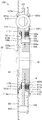
- FIG. 1 is a partially broken front view schematically showing a configuration of a torque damper device according to the present invention.
- FIG. 2 is a cross-sectional view schematically showing a configuration of a torque damper device taken along line 2-2 shown in FIG. 1.
- FIG. 3 is a partially enlarged view showing details of a configuration within a dashed circle A shown in FIG. 2.
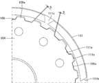
- FIG. 3 is a partially enlarged view showing details of a meshing portion between a first friction plate and an output hub shown in FIGS. 1 and 2 in a state where they are not meshed.
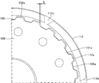
- FIG. 5 is a partially enlarged view showing a state where the first friction plate and the output hub shown in FIG. 4 are engaged with each other.
- FIG. 1 is a partially broken front view schematically showing a configuration of a torque damper device 100 according to the present invention.
- FIG. 2 is a cross-sectional view schematically showing the configuration of the torque damper device 100 as viewed from 2-2 shown in FIG.
- This torque damper device 100 is a machine mainly provided with an automatic transmission (so-called AT vehicle) that is provided between an engine and a transmission to reduce torque fluctuation of a driving force of the engine and transmit the torque to the transmission.
- AT vehicle automatic transmission
- the torque damper device 100 includes a first input plate 101 and a second input plate 102.
- the first input plate 101 and the second input plate 102 are components that are rotationally driven by a driving force from a vehicle engine (not shown), and are each formed by forming a metal material into a flat plate shape.
- the first input plate 101 and the second input plate 102 are opposed to each other with a gap between them, and are integrally connected by a plurality (four in the present embodiment) of rivets 103.
- a plurality of (four in the present embodiment) through-hole-shaped transmission body housing portions 101a, 102a are formed respectively, and hold an elastic transmission body 110 described later.
- the first input plate 101 forms one (left side in the figure) of the two side surfaces of the torque damper device 100, and is a plate holding hole formed of four through holes formed at equal intervals along the circumferential direction.
- a second intermediate plate 114 described later is held by 101b.
- the first input plate 101 is opposed to a position separated from a left end face in the figure of a flange body 107 described later, and a direction in which an inner peripheral edge portion 101c of the first input plate 101 is separated from the left end face (FIG. 2). At the left).
- a wide portion 108a is formed between the inner peripheral edge portion 101c and the flange body 107, and a narrow portion 108b is formed between the flange portion 107 and the opposing portion 101d outside the inner peripheral edge portion 101c.
- the second input plate 102 constitutes the other side (the right side in the figure) of the two sides of the torque damper device 100, and is a plate holding hole formed of eight through holes formed at equal intervals along the circumferential direction. 102b holds two first intermediate plates 112 described later.
- the first input plate 101 and the second input plate 102 are disposed to face each other via a flange body 107 extending from the output hub 104, and are integrally connected by a plurality (four in the present embodiment) of rivets 103. Have been.
- the first input plate 101 and the second input plate 102 are connected to an output shaft (not shown) such as an engine crankshaft, and integrally rotate.
- the output hub 104 is a component for outputting the rotational driving force input from the engine by the first input plate 101 and the second input plate 102 to the outside, and is formed by forming a metal material into a cylindrical shape. .
- the through hole at the center of the output hub 104 is a portion to which the input shaft 90 extending from the transmission, which is the output destination of the rotational driving force of the torque damper device 100, is connected.
- a spline for transmitting the driving force is formed.
- the outer peripheral portion of the output hub 104 is a portion that holds the flange body 107, the first friction plate 111, and the second friction plate 113, respectively, and has a cutout portion 104a and a friction plate holding portion 106, respectively.
- the notch portion 104a is a portion to which the flange body 107 is connected, and is formed by cutting out a part of the radially outer end portion of the output hub 104 in an annular shape in the thickness direction.
- the output hub 104 has a plurality of through holes formed along the circumferential direction at a portion corresponding to the notch portion 104a at the distal end portion, and penetrates these through holes and the flange body 107 in the axial direction.
- the flange body 107 is connected by the rivet 105.
- the flange body 107 is connected to the output hub 104 by twelve rivets 105.
- the rivet 105 is a component for integrally connecting the flange body 107 to the output hub 104, and has a head 105a in which both ends of a metal rod protrude radially outward in a disk shape.
- the rivet 105 connects the flange body 107 and the output hub 104 to each other with the head 105a protruding from each outer side surface of the flange body 107 and the output hub 104, respectively.
- the head portion 105a protruding from the side surface of the flange body 107 is formed to have a protruding amount that can be fitted and supported on an inner peripheral portion 113a of a second friction plate 113 described later.
- the head 105a is formed to have a thickness larger than the thickness of the second friction plate 113.
- the friction plate holding portion 106 is a portion that holds the first friction plate 111, and is formed at a radially outer end of the output hub 104 so as to extend in the axial direction.
- the friction plate holding portion 106 has a spline-shaped hub-side fitting portion 106a formed at a radially outer end portion of the output hub 104, and a plate formed on the inner peripheral portion of the first friction plate 111.
- the side fitting portion 111a is configured to fit.
- the friction plate holding portion 106 is formed to have a length in the axial direction longer than the total thickness of the first friction plate 111 and the first intermediate plate 112 which are overlapped with each other in the axial direction.
- the axial length of the friction plate holding portion 106 is formed to be longer than the total value of the thicknesses of the three first friction plates 111 and the two first intermediate plates 112. .
- the flange body 107 is a component for transmitting the rotational driving force input from the engine by the first input plate 101 and the second input plate 102 to the output hub 104, and is formed by forming a metal material into a flat annular shape. .
- the flange body 107 is disposed between the first input plate 101 and the second input plate 102, and the transmission body housing part that houses the elastic transmission body 110 at a position facing the transmission body housing parts 101a and 102a, respectively. 107a are formed.
- a portion between the transmission body accommodating portions 107a on the outer peripheral portion of the flange body 107 is formed so as to be recessed inward in the radial direction, and is formed so that the rivet 103 does not physically interfere.
- the flange body 107 has a lubricating liquid flow path 107b formed at a position facing the friction plate holding portion 106 in the output hub 104.
- the lubricating liquid flow path 107b is a through hole for guiding a lubricating liquid (not shown) flowing from the radially inner side through the narrow portion 108b to the friction plate holding part 106 side, and is provided at equal intervals along the circumferential direction.
- a plurality is formed. In the present embodiment, twelve lubricating liquid channels 107b are formed. That is, the torque damper device 100 according to the present embodiment is a wet-type torque damper device.
- the thickness of the flange body 107 is formed so as to fit in the notch 104a and be flush with the end face of the output hub 104 on the first input plate 101 side. As a result, a wide portion 108a and a narrow portion 108b are formed between the first input plate 101 and the end face of the flange body 107 on the first input plate 101 side.
- the wide portion 108a is a portion that receives the lubricating liquid discharged from the input shaft 90, and is a flow path formed in an annular shape between the inner peripheral portion 101c of the first input plate 101 and the side surface of the output hub 104. is there.
- the wide portion 108 a is formed so as to face each of the plurality of discharge ports 92 formed on the outer peripheral surface of the input shaft 90. 2 and 3, the flow of the lubricating liquid guided from the input shaft 90 into the torque damper device 100 is indicated by broken lines.
- the narrow portion 108b is a portion that guides the lubricating fluid that has flowed into the wide portion 108a to the second friction plate 113 and the lubricating fluid channel 107b, and is formed between the facing portion 101d of the first input plate 101 and the side surface of the flange body 107. It is formed in an annular shape with a width narrower than the wide portion 108a. Accordingly, the narrow portion 108b can increase the flow rate of the lubricating liquid flowing from the wide portion 108a to improve the cooling, cleaning, and lubricating properties of the second friction plate 113, and can reduce the lubricating liquid flow path 107b. The flowability to the first friction plate 111 via the first friction plate 111 can be improved.
- the narrow portion 108b may be formed to have a width relatively narrower than the wide portion 108a, one of the opposing end surfaces of the opposing portion 101d and the flange body 107 may protrude to the other side. May be formed. Therefore, the narrow portion 108b can also be formed by projecting at least a part of the end surface of the flange body 107 toward the facing portion 101d. Further, the wide portion 108a and the narrow portion 108b have a uniform width toward the outside in the radial direction, that is, even if the wide portion 108a or the narrow portion 108b is omitted, the flow of the lubricating liquid itself is secured. .
- the elastic transmission body 110 is a component for elastically transmitting the rotational driving force input from the engine by the first input plate 101 and the second input plate 102 to the output hub 104, and is configured by a metal coil spring. I have.
- the elastic transmission body 110 is fitted in a compressed and deformed state into transmission body housing portions 101a, 102a, 107a formed at positions facing each other in the first input plate 101, the second input plate 102, and the flange body 107. .
- the first friction plate 111 is a flat plate-shaped component pressed against the second input plate 102, the flange body 107, and the first intermediate plate 112, and punches a thin plate made of SPCC (cold rolled steel plate) into a ring. It is molded. On the inner peripheral portion of the first friction plate 111, a plate-side fitting portion 111a formed of an internal gear spline that is spline-fitted to a hub-side fitting portion 106a formed on the output hub 104 is formed. . In this case, as shown in FIG. 4 and FIG.
- the plate-side fitting portion 111a and the hub-side fitting portion 106a have a convex tooth-side circumferential length of the concave tooth side of the meshing spline teeth. Is formed longer than the length in the circumferential direction, and a gap S is formed in which the plate-side fitting portion 111a and the hub-side fitting portion 106a can be relatively displaced in the circumferential direction.
- a friction material 111b composed of a plurality of paper pieces is attached to both side surfaces in the axial direction of the first friction plate 111, and a groove 111c serving as a flow path of a lubricating liquid is formed between the friction materials.
- the first friction plates 111 are provided on the friction plate holding portion 106 alternately with the first intermediate plates 112 in the axial direction.
- three first friction plates 111 are provided on the friction plate holding unit 106.
- the two first friction plates 111 provided at both ends in the axial direction are connected to one (the right side in the drawing) of the two axial end portions of the flange body 107 and the flange body 107 of the second input plate 102. It is provided facing the respective inner side surfaces.
- the first intermediate plate 112 is a flat annular component pressed against the first friction plate 111, and is formed by annularly punching a thin plate made of SPCC (cold rolled steel plate).
- the first intermediate plate 112 is formed with a plate-shaped hooking portion 112a that projects outward in the radial direction while being bent at the outer peripheral portion, and is hooked on the plate holding hole 102b of the second input plate 102.
- four hook portions 112a are formed on the outer peripheral portion of the first intermediate plate 112 at equal intervals along the circumferential direction.
- the first intermediate plates 112 are provided on the friction plate holding portion 106 alternately with the first friction plates 111 in the axial direction.
- two first intermediate plates 112 are provided on the friction plate holding unit 106. That is, the second input plate 102 integrally holds the two first intermediate plates 112 via the eight plate holding holes 102b.
- the second friction plate 113 is a flat annular member pressed against the flange body 107 and the second intermediate plate 114, respectively, and is formed by annularly punching a thin plate made of SPCC (cold rolled steel plate).
- the second friction plate 113 has an inner peripheral portion 113a fitted and held at each radially outer edge of each head 105a of the twelve rivets 105 described above.
- friction materials made of a plurality of pieces of paper are attached to both axial side surfaces of the second friction plate 113, and grooves are formed between the friction materials. It is configured.
- the second friction plate 113 has a flow hole 113b formed in the flange body 107 at a position facing the lubricating liquid flow path 107b.
- the flow hole 113b is a through hole for guiding the lubricating liquid existing in the region (in the present embodiment, the narrow portion 108b) between the first input plate 101 and the flange body 107 to the lubricating liquid flow path 107b.
- eight flow holes 113b are formed radially inward of the friction material.
- the second friction plate 113 is provided on the outer side in the radial direction of each head 105 a of the twelve rivets 105, facing the other (left side in the drawing) side surface of the axially opposite ends of the flange body 107. .
- the second intermediate plate 114 is a flat annular component pressed against the second friction plate 113, and is formed by annularly punching a thin plate made of SPCC (cold rolled steel plate).
- the second intermediate plate 114 has a plate-shaped hooking portion 114a that is bent to the outer peripheral portion and protrudes outward in the radial direction, and the first input plate 101 In the plate holding hole 101b.
- four hook portions 114a are formed on the outer peripheral portion of the second intermediate plate 114 at equal intervals along the circumferential direction.
- the first input plate 101 integrally holds one second intermediate plate 114 via the four plate holding holes 101b.
- the second intermediate plate 114 is provided at a position radially outward from a portion of the first input plate 101 facing the facing portion 101d.
- a pressure body 115 is provided between the first input plate 101 and the second intermediate plate 114.
- the pressure body 115 presses the second friction plate 113 against the flange body 107 by pressing the second intermediate plate 114, and presses the first input plate 101 outward, thereby pressing the second input plate 102 to the first intermediate plate 112. And a component made of an elastic body for pressing the first friction plate 111 against the flange body 107.
- the pressure body 115 is formed by forming a flat ring-shaped spring steel into a weight shape. The pressure body 115 is provided at a position of the first input plate 101 facing the facing portion 101d.
- the operator fits the first friction plate 111 to the friction plate holding portion 106 of the output hub 104.
- the worker places the plate-side fitting portion 111a of the first friction plate 111 on the hub-side fitting portion 106a while alternately overlapping the first friction plates 111 and the first intermediate plates 112 from the flange body 107 side. Fit.
- the worker can easily receive the first friction plate 111 by providing the flange body 107 at one end (left side in the drawing) of the friction plate holding portion 106, so that the operator can easily perform the first operation in a state where the position in the axial direction is defined.
- the first friction plate 111 and the first intermediate plate 112 can be arranged on the friction plate holding portion 106 while alternately overlapping.
- the operator can determine the radial position by fitting the first friction plate 111 to the hub-side fitting portion 106a, and also allow the first intermediate plate 112 to be separated by the outer peripheral surface of the hub-side fitting portion 106a. Therefore, the first friction plates 111 and the first intermediate plates 112 can be easily arranged alternately on the friction plate holding portion 106 in a state where the position in the radial direction is defined.
- the operator arranges the second friction plate 113 adjacent to the side surface of the flange body 107 and attaches the second intermediate plate to the second friction plate 113.
- the plate 114 is arranged adjacent.
- the second friction plate 113 is easily positioned and arranged with respect to the flange body 107 because the radial position is defined by fitting the inner peripheral portion 113a to the head 105a of the rivet 105. Can be.
- the operator prepares the first input plate 101, the second input plate 102, the elastic transmission body 110, and the pressure body 115, and assembles them to the flange body 107.
- the worker after accommodating the elastic transmission members 110 in the four transmission member receiving portions 107a of the flange 107, respectively, arranges the second input plate 102 in opposition to the first intermediate plate 112 and alternates with each other.
- the first friction plate 111 and the first intermediate plate 112, which are overlapped with each other, are arranged so as to be sandwiched by the flange body 107.
- the worker accommodates the elastic transmission body 110 in the transmission body accommodation section 102a of the second input plate 102 and sets the hook 112a of the first intermediate plate 112 to the plate holding hole 102b of the second input plate 102. Hook on.
- the operator arranges the first input plate 101 to face the second intermediate plate 114 via the pressure body 115, and sandwiches the pressure body 115, the second intermediate plate 114, and the second friction plate 113 with the flange body 107. So that In this case, the worker accommodates the elastic transmission body 110 in the transmission body accommodation section 101a of the first input plate 101, and sets the hook 114a of the second intermediate plate 114 to the plate holding hole 101b of the first input plate 101. Hook on.
- the operator integrally connects the first input plate 101 and the second input plate 102 arranged on both axial sides of the flange body 107 with the rivets 103. Thereby, the operator can assemble the torque damper device 100.
- various adjustment operations and test operations are required to complete the torque damper device 100, but since these various operations are not directly related to the present invention, the description thereof will be omitted.
- the torque damper device 100 is disassembled for output adjustment, maintenance, or the like, it can be disassembled by a procedure reverse to the above-described assembly procedure.
- the completed torque damper device 100 is assembled on a power transmission path between the engine and the transmission in an automobile assembling process.
- the input shaft 90 extending from the transmission is fitted and connected to the inner peripheral surface of the output hub 104.
- a lubricating liquid supply passage 91 for supplying lubricating liquid into the torque damper device 100 is formed in the input shaft 90 so as to extend in the axial direction, and a plurality of lubricating liquid supply passages 91 on the outer peripheral surface of the input shaft 90 are formed. Open at the location.
- the discharge ports 92 which are openings of the lubricating liquid supply passage 91, are formed at a plurality of positions on the outer peripheral surface of the input shaft 90 facing the wide portion 108a. ing.
- the lubricating liquid oil or the like that can ensure the cooling property, the cleaning property and the lubricating property of the first friction plate 111 and the second friction plate 113 is mainly used.
- This torque damper device 100 is disposed between an engine and a transmission in a vehicle, and absorbs torque fluctuations from the engine during idling when the engine is started and the vehicle is stopped while the vehicle is not running. Transmit to the transmission.
- the first input plate 101 and the second input plate 102 are driven to rotate integrally by the rotational driving force from the engine, and the first input plate 101 and the second input plate
- the first intermediate plate 112 and the second intermediate plate 114 integrally connected to 102 also rotate integrally.
- the flange body 107 and the output hub 104 are elastically connected to the first input plate 101 and the second input plate 102 via the elastic transmission body 110, respectively, the first input plate 101 and the second input plate It is driven to rotate together with the plate 102.
- first friction plate 111 meshed with the output hub 104 via the friction plate holding portion 106 is brought into close contact with the first intermediate plate 112 by the elastic force of the pressure body 115 and is also provided on the flange body 107 and the second input plate 102. Each is in close contact. Thereby, the first friction plate 111 drives the output hub 104 to rotate.
- the second friction plate 113 is in close contact with the second intermediate plate 114 and the flange body 107 by the elastic force of the pressure member 115. Accordingly, the second friction plate 113 drives the output hub 104 to rotate.
- the torque damper device 100 when a small torque fluctuation occurs in the rotational driving force from the engine, the torque damper device 100 includes at least the first friction plate 111 and the second friction plate 113 which are in close contact with the flange body 107.
- One of the members slides frictionally with at least one of the flange body 107, the first intermediate plate 112, and the second intermediate plate 114 to generate low hysteresis.
- the torque damper device 100 absorbs the small torque fluctuation due to low hysteresis generated by at least one of the first friction plate 111 and the second friction plate 113 that are in close contact with the flange body 107 and frictionally sliding.
- the torque damper device 100 When torque fluctuation larger than the small torque fluctuation occurs in the rotational driving force from the engine, the torque damper device 100 generates a high hysteresis in addition to the low hysteresis. Specifically, in the torque damper device 100, as shown in FIG. 5, the tooth surface at which the hub-side fitting portion 106a of the output hub 104 and the plate-side fitting portion 111a of the first friction plate 111 mesh with each other is large. By shifting to the tooth surface on the side where the gap S is formed due to the torque fluctuation, frictional sliding occurs between the first friction plate 111 and the first intermediate plate 112, and high hysteresis occurs.
- the torque damper device 100 a tooth surface in which the hub-side fitting portion 106a of the output hub 104 and the plate-side fitting portion 111a of the first friction plate 111 mesh with each other is formed on the opposite side in the circumferential direction from the tooth surface. High hysteresis is not generated until the gap S that has been formed is eliminated and the tooth surfaces forming the gap S mesh with each other. As a result, the torque damper device 100 has the large torque fluctuation due to the high hysteresis generated when the first friction plate 111 frictionally slides between the flange body 107, the first intermediate plate 112, and the second input plate 102. Absorb some or all of
- lubricating liquid is supplied from the input shaft 90 when the engine is operating.
- the lubricating liquid discharged from the discharge port 92 of the input shaft 90 forms a wide portion 108 a formed by the first input plate 101 and the output hub 104 and a narrow portion formed by the first input plate 101 and the flange body 107.
- the friction plate holding portion 106 and the friction plate holding portion 106 are supplied to the second friction plate 113 through the lubricating fluid passage 107b formed in the flange body 107 and the circulation hole 113b formed in the second friction plate 113, respectively. It is supplied to the first friction plate 111. Thereby, the second friction plate 113 and the first friction plate 111 are cooled, cleaned and lubricated.
- the displacement of the torque damper device 100 in the radial direction is restricted by fitting to the outer peripheral surface of the output hub 104 to which the input shaft 90 is connected.
- a hub-side fitting portion 106a for holding the plurality of first friction plates 111 in a state in which displacement in the axial direction is allowed while restricting displacement in the circumferential direction is formed on the outer peripheral surface of the hub.
- the torque damper device 100 can hold the hub-side fitting portion 106a simply by inserting the plurality of first friction plates 111 from the axial direction, the first friction plates 111 for generating high hysteresis can be held. Can be improved in ease of assembly and maintenance.
- the torque damper device 100 is configured to include the three first friction plates 111 and the two first intermediate plates 112.
- the torque damper device 100 may be configured to include the plurality of first friction plates 111 and the plurality of first intermediate plates 112.
- the torque damper device 100 can reduce the operational and economical burden when manufacturing the torque damper device 100.
- the first friction plate 111 may be configured to include the first friction plate 111 in which the plate-side fitting portions 111a having different gaps S between the plurality of first friction plates 111 are formed. According to this, the torque damper device 100 can set a plurality of timings at which a high hysteresis is generated, and generate a high hysteresis for each finer variation with respect to the engine torque variation, that is, increase the number of stages of the hysteresis. Can be done.
- the torque damper device 100 is configured to form the gap S between the plate-side fitting portion 111a of the first friction plate 111 and the hub-side fitting portion 106a of the output hub 104. . That is, the plate-side fitting portion 111a and the hub-side fitting portion 106a are formed such that the circumferential length of the concave tooth side of the meshing spline teeth is longer than the circumferential length of the convex tooth side.
- a gap S is formed in which the side fitting portion 111a and the hub side fitting portion 106a can be relatively displaced in the circumferential direction.
- the plate-side fitting portion 111a and the hub-side fitting portion 106a are formed such that the circumferential length of the concave tooth side and the circumferential length of the convex tooth side of the meshing spline teeth are substantially the same. Then, the plate-side fitting portion 111a and the hub-side fitting portion 106a may be formed so as to fit in a state in which relative displacement is not possible in the circumferential direction. According to this, the torque damper device 100 can immediately generate high hysteresis with respect to the torque fluctuation from the engine.
- the torque damper device 100 is configured to include the second friction plate 113 and the second intermediate plate 114, respectively. Accordingly, the torque damper device 100 can enhance the hysteresis generated by the first friction plate 111. Further, the torque damper device 100 can suppress the torque fluctuation by generating the hysteresis even when the first friction plate 111 has a low torque fluctuation that does not cause the hysteresis.
- the torque damper device 100 may be configured by omitting the second friction plate 113 and the second intermediate plate 114, respectively. In this case, in the torque damper device 100, the pressure body 115 may be provided between the second input plate 102 and the flange body 107, or may be provided between the first input plate 101 and the flange body 107.
- the first intermediate plate 112 is provided between the flange body 107 and the first friction plate 111, and the pressure body 115 is provided between the first intermediate plate 112 and the flange body 107.
- the torque damper device 100 includes a first intermediate plate 112 provided between the second input plate 102 and the first friction plate 111, and a first intermediate plate 112 provided between the first intermediate plate 112 and the second input plate 102.
- a pressure body 115 can be provided.
- two first intermediate plates 112 may be provided between the two first friction plates 111, and the pressure body 115 may be provided between the two first intermediate plates 112.
- a second intermediate plate 114 is provided between the flange body 107 and the first input plate 101, and a pressure body 115 is provided between the first input plate 101 and the second intermediate plate 114.
- the torque damper device 100 is configured such that the output hub 104 and the flange body 107 are formed separately from each other and connected by the rivets 105.
- the output hub 104 and the flange body 107 can also be configured as one integrated part.
- the second friction plate 113 has a convex shape such that all or a part of the inner peripheral portion 113a of the second friction plate 113 is fitted to the side surface of the output hub 104 on which the flange body 107 is integrally formed. It is preferable to provide a protruding projection.
- the flange body 107 is formed by forming the lubricating liquid flow path 107b at a position facing the friction plate holding portion 106.
- the flange body 107 can also be formed at a position where the lubricating liquid flow path 107b is shifted with respect to the friction plate holding section 106, for example, at a position radially outside the friction plate holding section 106.
- the flange body 107 may be configured by omitting the lubricating liquid flow path 107b.
- the second friction plate 113 can be configured by omitting the flow holes 113b.
- the hub-side fitting portion 106a and the plate-side fitting portion 111a are configured with a large number of spline teeth.
- the hub-side fitting portion 106a and the plate-side fitting portion 111a may be configured to include at least one concave and one convex portion that mesh with each other.
Landscapes
- Engineering & Computer Science (AREA)
- General Engineering & Computer Science (AREA)
- Mechanical Engineering (AREA)
- Physics & Mathematics (AREA)
- Acoustics & Sound (AREA)
- Aviation & Aerospace Engineering (AREA)
- Mechanical Operated Clutches (AREA)
Abstract
高ヒステリシスを幅広い範囲で設定することができるとともに、高ヒステリシスを発生させるための高摩擦材の組付け性およびメンテナンス性を向上させることができるトルクダンパー装置を提供する。 トルクダンパー装置100は、エンジンの回転駆動力によって回転駆動する第1入力プレート101と第2入力プレート102との間に出力ハブ104およびフランジ体107を備えている。出力ハブ104は、円筒状に形成されるとともに径方向外側に張り出した部分にフランジ体107が取り付けられている。また、出力ハブ104には、外周面上に摩擦プレート保持部106が形成されている。摩擦プレート保持部106は、第1摩擦プレート111のプレート側嵌合部111aが嵌合するとともに軸方向の長さが第1摩擦プレート111および第1中間プレート112の総量の厚さよりも長く形成されている。
Description
本発明は、エンジンのトルク変動を吸収するトルクダンパー装置に関する。
従来から、エンジンを備えた自走式車両においては、エンジンと変速機との動力伝達経路上にトルクダンパー装置が設けられている。トルクダンパー装置は、互いに摩擦接触する2つの回転体間で発生させたヒステリシストルクによってエンジンのトルク変動を吸収する。例えば、下記特許文献1には、ミッション側回転軸が連結されるボス部材から径方向外側に延びるドリブンプレートの軸方向両側に高摩擦材がそれぞれ配置されるとともに、これらの高摩擦材の各外側に樹脂材製のスライド部材を介して低摩擦材がそれぞれ配置されて低ヒステリシスおよび高ヒステリシスを発生させることができるトルク変動吸収装置(以下、「トルクダンパー装置」という)が開示されている。
しかしながら、上記特許文献1に記載されたトルクダンパー装置においては、高ヒステリシスがドリブンプレートの両側に設けられた2つの高摩擦材によって発生されるため、これ以上高摩擦材を配置することができず発生させる高ヒステリシスに制限があるという問題がある。また、上記特許文献1に記載されたトルクダンパー装置においては、2つの高摩擦材が互い異なる部品である2つのスライド部材に取り付けられるため組み付け作業が煩雑であるとともにメンテナンス負担も大きいという問題があった。
本発明は上記問題に対処するためなされたもので、その目的は、高ヒステリシスを幅広い範囲で設定することができるとともに、高ヒステリシスを発生させるための高摩擦材の組付け性およびメンテナンス性を向上させることができるトルクダンパー装置を提供することにある。
上記目的を達成するため、本発明の特徴は、平板環状に形成されてエンジンの駆動力によって回転駆動する第1入力プレートと、平板環状に形成されて第1入力プレートに対向した位置に配置されて同第1入力プレートと一体的に回転駆動する第2入力プレートと、第1入力プレートおよび第2入力プレートと同軸上に配置されてこれらの第1入力プレートおよび第2入力プレートの回転駆動力によって回転駆動する円筒状の出力ハブと、出力ハブの外周面から径方向外側に張り出して第1入力プレートと第2入力プレートとの間に設けられるフランジ体と、第1入力プレートおよび第2入力プレートとフランジ体との間に設けられて第1入力プレートおよび第2入力プレートの回転駆動力をフランジ体に伝達する弾性体で構成された弾性伝達体と、出力ハブの径方向外側でフランジ体と第2入力プレートとの間に設けられた平板環状の複数の第1摩擦プレートと、第2入力プレートに一体的に回転駆動する平板環状に形成されて複数の第1摩擦プレート間にそれぞれ配置される複数の第1中間プレートと、第1入力プレートと第2入力プレートとの間に設けられてフランジ体と第2入力プレートとの間で複数の第1摩擦プレートと複数の第1中間プレートとを互いに密着させるプレッシャー体とを備え、出力ハブは、外周面上に軸方向に沿って互いに重ねられた複数の第1摩擦プレートおよび複数の第1中間プレートの厚さ以上の長さに形成されて複数の第1摩擦プレートがそれぞれ嵌合する摩擦プレート保持部と、摩擦プレート保持部上に軸方向に沿って径方向に突出または凹んで形成されたハブ側嵌合部とをそれぞれ有し、複数の第1摩擦プレートは、内周部にハブ側嵌合部に嵌合する凹状または凸状に形成されたプレート側嵌合部を有することにある。
このように構成した本発明の特徴によれば、トルクダンパー装置は、入力軸が連結される出力ハブの外周面に嵌合することで径方向の変位が規制されるとともに同外周面上に周方向の変位を規制しつつ軸方向への変位を許容した状態で複数の第1摩擦プレートを保持するハブ側嵌合部が形成されているため、このハブ側嵌合部に保持させた第1摩擦プレートの数を適宜設定することで高ヒステリシスを幅広い範囲で設定することができる。この場合、トルクダンパー装置は、ハブ側嵌合部に軸方向から複数の第1摩擦プレートを挿し込むだけで保持させることができるため、高ヒステリシスを発生させるための第1摩擦プレートの組付け性およびメンテナンス性を向上させることができる。
また、本発明の他の特徴は、前記トルクダンパー装置において、ハブ側嵌合部およびプレート側嵌合部は、互いに噛み合う部分における各周方向の長さが互いに異なる長さに形成されて出力ハブと第1摩擦プレートとが周方向に相対変位可能な隙間が形成されていることにある。
このように構成した本発明の他の特徴によれば、トルクダンパー装置は、ハブ側嵌合部およびプレート側嵌合部における各周方向の長さが互いに異なる長さに形成されて両者が周方向に相対変位可能な隙間が形成されることで出力ハブと第1摩擦プレートとが周方向に相対変位可能に形成されているため、エンジンのトルク変動の大きに応じて高ヒステリシスを発生させることができる。
また、本発明の他の特徴は、前記トルクダンパー装置において、複数の第1摩擦プレートは、互いに同じ形状に形成されていることにある。
このように構成した本発明の他の特徴によれば、トルクダンパー装置は、複数の第1摩擦プレートが互いに同じ形状に形成されているため、トルクダンパー装置を製造する際の作業的および経済的な負担を軽減することができる。
また、本発明の他の特徴は、前記トルクダンパー装置において、複数の第1摩擦プレートは、前記隙間が互いに異なるプレート側嵌合部が形成された第1摩擦プレートを含んで構成されていることにある。
このように構成した本発明の他の特徴によれば、トルクダンパー装置は、複数の第1摩擦プレートが前記隙間が互いに異なるプレート側嵌合部が形成された第1摩擦プレートを含んで構成されているため、高ヒステリシスを発生させるタイミングを複数設定することができエンジンのトルク変動に対してよりきめ細かな変動ごとに高ヒステリシスを発生、すなわち、ヒステリシスの発生を多段化させることができる。
また、本発明の他の特徴は、前記トルクダンパー装置において、さらに、第1入力プレートとフランジ部との間に設けられた平板環状の複数の第2摩擦プレートと、第1入力プレートに一体的に回転駆動する平板環状に形成されて第2摩擦プレートに隣接配置された第2中間プレートとを備え、プレッシャー体は、第1入力プレートと第2中間プレートとの間に設けられて同第1入力プレートを介して第2入力プレートをフランジ部側に弾性的に変位させるとともに同第2中間プレートを介して第2摩擦プレートをフランジ部に押圧することにある。
このように構成した本発明の他の特徴によれば、トルクダンパー装置は、フランジ体に対して第2摩擦プレートが常に摩擦接触しているため、第1摩擦プレートが発生させるヒステリシスを増強することができる。また、本発明に係るトルクダンパー装置は、ハブ側嵌合部とプレート側嵌合部との嵌合部分に隙間を形成してエンジンからのトルク変動が所定の大きさ以上の場合に第1摩擦プレートが発生させるヒステリシスを発生させるように構成した場合には、第1摩擦プレートがヒステリシスを発生させるに至らない低いトルク変動時にもヒステリシスを発生させてトルク変動を抑えることができる。
また、本発明の他の特徴は、前記トルクダンパー装置において、出力ハブおよびフランジ体は、互いに別体で構成されて出力ハブおよびフランジ体を貫通するリベットで互いに連結されており、リベットは、フランジ体から突出した頭部を有して同フランジ体の周方向に沿って複数設けられているとともに、同頭部に第2摩擦プレートが嵌合していることにある。
このように構成した本発明の他の特徴によれば、トルクダンパー装置は、第2摩擦プレートが出力ハブとフランジ体とを連結するリベットの頭部に嵌合しているため、トルクダンパー装置の部品点数を少なくしてトルクダンパー装置を製造する際の作業的および経済的な負担を軽減することができる。
また、本発明の他の特徴は、前記トルクダンパー装置において、フランジ体は、同フランジ体の両側間で潤滑液を流通させるための貫通孔からなる潤滑液流路が形成されていることにある。
このように構成した本発明の他の特徴によれば、トルクダンパー装置は、フランジ体における軸方向の両側間で潤滑液を流通させるための貫通孔からなる潤滑液流路が形成されているため、トルクダンパー装置内における潤滑油の流通性を促進させて冷却性、洗浄性および潤滑性を向上させることができる。
また、本発明の他の特徴は、前記トルクダンパー装置において、潤滑液流路は、摩擦プレート保持部に面する位置に形成されていることにある。
このように構成した本発明の他の特徴によれば、トルクダンパー装置は、潤滑液流路が摩擦プレート保持部に面する位置に形成されているため、摩擦プレート保持部に対して潤滑油を積極的に導くことができ、第1摩擦プレートおよび第1中間プレートの冷却性、洗浄性および潤滑性を向上させることができる。
また、本発明の他の特徴は、前記トルクダンパー装置において、第2摩擦プレートは、潤滑液流路に対向する位置に貫通孔からなる流通孔が形成されていることにある。
このように構成した本発明の他の特徴によれば、トルクダンパー装置は、第2摩擦プレートにおける潤滑液流路に対向する位置に貫通孔からなる流通孔が形成されているため、潤滑液流路の一部または全部が第2摩擦プレートによって塞がれることを防止することができ、摩擦プレート保持部への潤滑油の流通性を確保して第1摩擦プレートおよび第1中間プレートの冷却性、洗浄性および潤滑性を向上させることができる。
また、本発明の他の特徴は、前記トルクダンパー装置において、出力ハブは、同出力ハブの回転駆動力を伝達するために連結される入力軸にトルクダンパー装置内に潤滑油を供給するための潤滑油供給路が形成されており、出力ハブおよびフランジ体のうちの少なくとも一方と第1入力プレートとの間の隙間に径方向内側に向かって開口する幅広部が形成されるとともに同幅広部よりも径方向外側に前記隙間の幅が狭くなる幅狭部が形成されていることにある。
このように構成した本発明の他の特徴によれば、トルクダンパー装置は、出力ハブおよびフランジ体のうちの少なくとも一方と第1入力プレートとの間の隙間に径方向内側に向かって開口する幅広部が形成されるとともに同幅広部よりも径方向外側に前記隙間の幅が狭くなる幅狭部が形成されているため、入力軸から供給された潤滑液の流速を幅狭部で速めて第2摩擦プレートに供給することができ潤滑液による冷却性、洗浄性および潤滑性を向上させることができる。また、トルクダンパー装置は、フランジ体に潤滑液流路が形成されている場合には、第1摩擦プレートに対する潤滑液による冷却性、洗浄性および潤滑性を向上させることができる。
以下、本発明に係るトルクダンパー装置の一実施形態について図面を参照しながら説明する。図1は、本発明に係るトルクダンパー装置100の構成を概略的に示す一部破断正面図である。また、図2は、図1に示す2-2から見たトルクダンパー装置100の構成を概略的に示す断面図である。このトルクダンパー装置100は、主として自動変速機を備えた自動車(所謂AT車)において、エンジンと変速機との間に設けられてエンジンの駆動力のトルク変動を緩和して変速機に伝達する機械装置である。
(トルクダンパー装置100の構成)
トルクダンパー装置100は、第1入力プレート101および第2入力プレート102をそれぞれ備えている。第1入力プレート101および第2入力プレート102は、図示しない車両のエンジンからの駆動力によって回転駆動する部品であり、それぞれ金属材料を平板環状に形成して構成されている。これらの第1入力プレート101および第2入力プレート102は、両者間に隙間を介して互いに対向配置されて複数(本実施形態においては、4つ)のリベット103によって一体的に連結されている。また、第1入力プレート101および第2入力プレート102には、周方向に沿って等間隔で互いに対向する位置に複数(本実施形態においては4つ)の貫通孔状の伝達体収容部101a,102aがそれぞれ形成されており、後述する弾性伝達体110を保持している。
トルクダンパー装置100は、第1入力プレート101および第2入力プレート102をそれぞれ備えている。第1入力プレート101および第2入力プレート102は、図示しない車両のエンジンからの駆動力によって回転駆動する部品であり、それぞれ金属材料を平板環状に形成して構成されている。これらの第1入力プレート101および第2入力プレート102は、両者間に隙間を介して互いに対向配置されて複数(本実施形態においては、4つ)のリベット103によって一体的に連結されている。また、第1入力プレート101および第2入力プレート102には、周方向に沿って等間隔で互いに対向する位置に複数(本実施形態においては4つ)の貫通孔状の伝達体収容部101a,102aがそれぞれ形成されており、後述する弾性伝達体110を保持している。
第1入力プレート101は、トルクダンパー装置100における両側面のうちの一方(図示左側)の側面を構成しており、周方向に沿って等間隔で形成された4つの貫通孔からなるプレート保持孔101bに後述する第2中間プレート114を保持している。また、第1入力プレート101は、後述するフランジ体107の図示左側端面から離隔した位置に対向配置されるとともに、第1入力プレート101の内周縁部101cが前記左側端面から離隔する方向(図2において左側)に屈曲して形成されている。これにより、内周縁部101cとフランジ体107との間に幅広部108aが形成されるとともに、この内周縁部101cよりも外側の対向部101dとフランジ体107との間に幅狭部108bが形成されている。
第2入力プレート102は、トルクダンパー装置100における両側面のうちの他方(図示右側)の側面を構成しており、周方向に沿って等間隔で形成された8つの貫通孔からなるプレート保持孔102bに後述する2つの第1中間プレート112を保持している。これらの第1入力プレート101および第2入力プレート102は、出力ハブ104から延びるフランジ体107を介して互いに対向配置されて複数(本実施形態においては、4つ)のリベット103によって一体的に連結されている。そして、これらの第1入力プレート101および第2入力プレート102は、エンジンのクランク軸などの出力軸(図示せず)に連結されており一体的に回転駆動する。
出力ハブ104は、第1入力プレート101および第2入力プレート102がエンジンから入力した回転駆動力を外部に対して出力するための部品であり、金属材料を円筒状に形成して構成されている。この場合、出力ハブ104の中心部の貫通孔は、トルクダンパー装置100の回転駆動力の出力先である変速機から延びる入力軸90が連結される部分であり、円筒体の内周面に回転駆動力の伝達のためのスプラインが形成されている。一方、出力ハブ104の外周部は、フランジ体107、第1摩擦プレート111および第2摩擦プレート113をそれぞれ保持する部分であり、切欠き部104aおよび摩擦プレート保持部106がそれぞれ形成されている。
切欠き部104aは、フランジ体107が連結される部分であり、出力ハブ104における径方向外側の先端部分の一部が厚さ方向に円環状に切り欠かれて形成されている。この場合、出力ハブ104は、先端部分における切欠き部104aに対応する部分に周方向に沿って複数の貫通孔が形成されており、これらの貫通孔およびフランジ体107をそれぞれ軸方向に貫通するリベット105によってフランジ体107が連結されている。本実施形態においては、フランジ体107は、12個のリベット105によって出力ハブ104に連結されている。
リベット105は、フランジ体107を出力ハブ104に一体的に連結するための部品であり、金属製の棒体の両端部が径方向外側に円板状に張り出した頭部105aを有して構成されている。すなわち、リベット105は、フランジ体107および出力ハブ104の各外側側面に頭部105aがそれぞれ突出した状態でフランジ体107と出力ハブ104とを互いに連結している。この場合、フランジ体107の側面から突出した頭部105aは、後述する第2摩擦プレート113の内周部113aに嵌合して支持可能な張り出し量に形成されている。具体的には、頭部105aは、第2摩擦プレート113の厚さよりも厚い厚さに形成されている。
摩擦プレート保持部106は、図3に示すように、第1摩擦プレート111を保持する部分であり、出力ハブ104の径方向外側の先端部に軸方向に延びて形成されている。この場合、摩擦プレート保持部106は、出力ハブ104の径方向外側の先端部にスプライン状のハブ側嵌合部106aが形成されており、第1摩擦プレート111の内周部に形成されたプレート側嵌合部111aが嵌合するように構成されている。
また、摩擦プレート保持部106は、軸方向の長さが軸方向に互いに重ねられる第1摩擦プレート111および第1中間プレート112の総量の厚さよりも長い長さに形成されている。本実施形態においては、摩擦プレート保持部106の軸方向の長さは、3つの第1摩擦プレート111および2つの第1中間プレート112の厚さの合計値よりも長い長さに形成されている。
フランジ体107は、第1入力プレート101および第2入力プレート102がエンジンから入力した回転駆動力を出力ハブ104に伝達するための部品であり、金属材料を平板環状に形成して構成されている。このフランジ体107は、第1入力プレート101と第2入力プレート102との間に配置されており、伝達体収容部101a,102aにそれぞれ対向する位置に弾性伝達体110を収容する伝達体収容部107aが形成されている。この場合、フランジ体107の外周部における各伝達体収容部107aの間の部分は、径方向内側に凹状に凹んで形成されており前記リベット103が物理的に干渉しないように形成されている。
また、フランジ体107は、出力ハブ104における摩擦プレート保持部106に対向する位置に潤滑液流路107bが形成されている。潤滑液流路107bは、幅狭部108bを径方向内側から流れてくる潤滑液(図示せず)を摩擦プレート保持部106側に導くための貫通孔であり、周方向に沿って等間隔に複数形成されている。本実施形態においては、潤滑液流路107bは、12個形成されている。すなわち、本実施形態におけるトルクダンパー装置100は、湿式型のトルクダンパー装置である。
また、フランジ体107の厚さは、前記切欠き部104a内に収まって出力ハブ104における第1入力プレート101側の端面と面一になる厚さに形成されている。これにより、フランジ体107における第1入力プレート101側の端面と同第1入力プレート101との間には、幅広部108aと幅狭部108bとがそれぞれ形成される。
幅広部108aは、入力軸90から吐出された潤滑液を受け入れる部分であり、第1入力プレート101の内周縁部101cと出力ハブ104の側面との間に円環状に形成されている流路である。この幅広部108aは、入力軸90の外周面上に開口して形成された複数の吐出口92にそれぞれ対向して形成されている。なお、図2および図3においては、入力軸90からトルクダンパー装置100内に導かれる潤滑液の流れを破線で示している。
幅狭部108bは、幅広部108a内に流れ込んだ潤滑液を第2摩擦プレート113および潤滑液流路107bに導く部分であり、第1入力プレート101の対向部101dとフランジ体107の側面との間に幅広部108aよりも狭い幅で円環状に形成されている。これにより、幅狭部108bは、幅広部108aから流れてくる潤滑液の流速を速めて第2摩擦プレート113の冷却性、洗浄性および潤滑性を向上させることができるとともに潤滑液流路107bを介した第1摩擦プレート111への流通性を向上させることができる。
なお、幅狭部108bは、幅広部108aに対して相対的に狭い幅で形成されていればよいため、対向部101dおよびフランジ体107における互いに対向する端面の一方を他方側に張り出させることで形成してもよい。したがって、幅狭部108bは、フランジ体107における端面の少なくとも一部を対向部101d側に張り出させることによって形成することもできる。また、幅広部108aおよび幅狭部108bは、径方向外側に向かって均一な幅、すなわち、幅広部108aまたは幅狭部108bが省略されていても潤滑液の流通自体は確保されるものである。
弾性伝達体110は、第1入力プレート101および第2入力プレート102がエンジンから入力した回転駆動力を出力ハブ104に弾性的に伝達するための部品であり、金属製のコイルスプリングで構成されている。この弾性伝達体110は、第1入力プレート101、第2入力プレート102およびフランジ体107における互いに対向する位置に形成された伝達体収容部101a,102a,107aに圧縮変形した状態で嵌め込まれている。
第1摩擦プレート111は、第2入力プレート102、フランジ体107および第1中間プレート112にそれぞれ押し当てられる平板環状の部品であり、SPCC(冷間圧延鋼板)材からなる薄板材を環状に打ち抜いて成形されている。この第1摩擦プレート111の内周部には、出力ハブ104に形成されたハブ側嵌合部106aにスプライン嵌合する内歯歯車状のスプラインからなるプレート側嵌合部111aが形成されている。この場合、プレート側嵌合部111aおよびハブ側嵌合部106aは、図4および図5にそれぞれ示すように、互いに噛み合うスプライン歯における凹状の歯側の周方向の長さが凸状の歯側の周方向の長さよりも長く形成されてプレート側嵌合部111aとハブ側嵌合部106aとが周方向に相対変位可能な隙間Sが形成されている。
また、第1摩擦プレート111における軸方向の両側面には、複数の紙片からなる摩擦材111bが貼り付けられているとともに各摩擦材間に潤滑液の流通路となる溝部111cが形成されて構成されている。この第1摩擦プレート111は、摩擦プレート保持部106上において軸方向に第1中間プレート112と交互に設けられている。本実施形態においては、第1摩擦プレート111は、摩擦プレート保持部106上にて3つ設けられている。この場合、軸方向の両端に設けられている2つの第1摩擦プレート111は、フランジ体107における軸方向両端部のうちの一方(図示右側)の側面および第2入力プレート102におけるフランジ体107に対向する内側面にそれぞれ面して設けられている。
第1中間プレート112は、前記第1摩擦プレート111に押し当てられる平板環状の部品であり、SPCC(冷間圧延鋼板)材からなる薄板材を環状に打ち抜いて成形されている。この場合、第1中間プレート112は、外周部に屈曲しつつ径方向外側に張り出した板状の引掛け部112aが形成されており、第2入力プレート102のプレート保持孔102bに引っ掛けられている。本実施形態においては、引掛け部112aは、第1中間プレート112の外周部に周方向に沿って等間隔に4つ形成されている。
この第1中間プレート112は、摩擦プレート保持部106上において軸方向に第1摩擦プレート111と交互に設けられている。本実施形態においては、第1中間プレート112は、摩擦プレート保持部106上にて2つ設けられている。すなわち、第2入力プレート102は、8つのプレート保持孔102bを介して2つの第1中間プレート112をそれぞれ一体的に保持している。
第2摩擦プレート113は、フランジ体107および第2中間プレート114にそれぞれ押し当てられる平板環状の部品であり、SPCC(冷間圧延鋼板)材からなる薄板材を環状に打ち抜いて成形されている。この第2摩擦プレート113は、内周部113aが前記した12個のリベット105の各頭部105aにおける径方向外側の各縁部にそれぞれ嵌合して保持されている。また、第2摩擦プレート113における軸方向の両側面には、前記第1摩擦プレート111と同様に、複数の紙片からなる摩擦材が貼り付けられているとともにこれらの各摩擦材間に溝部が形成されて構成されている。
さらに、第2摩擦プレート113は、フランジ体107における潤滑液流路107bに対向する位置に流通孔113bが形成されている。流通孔113bは、第1入力プレート101とフランジ体107との間の領域(本実施形態においては、幅狭部108b)に存在する潤滑液を潤滑液流路107bに導くための貫通孔であり、第2摩擦プレート113の周方向に沿って等間隔に複数形成されている。本実施形態においては、流通孔113bは、前記摩擦材に対して径方向内側に8つ形成されている。この第2摩擦プレート113は、12個のリベット105の各頭部105aの径方向外側においてフランジ体107における軸方向の両端部のうちの他方(図示左側)の側面に面して設けられている。
第2中間プレート114は、前記第2摩擦プレート113に押し当てられる平板環状の部品であり、SPCC(冷間圧延鋼板)材からなる薄板材を環状に打ち抜いて成形されている。この場合、第2中間プレート114は、前記第1中間プレート112と同様に、外周部に屈曲しつつ径方向外側に張り出した板状の引掛け部114aが形成されており、第1入力プレート101のプレート保持孔101bに引っ掛けられている。本実施形態においては、引掛け部114aは、第2中間プレート114の外周部に周方向に沿って等間隔に4つ形成されている。
すなわち、第1入力プレート101は、4つのプレート保持孔101bを介して1つの第2中間プレート114を一体的に保持している。この場合、第2中間プレート114は、第1入力プレート101における対向部101dと対向する部分からの径方向外側の位置に設けられている。また、第1入力プレート101と第2中間プレート114との間には、プレッシャー体115が設けられている。
プレッシャー体115は、第2中間プレート114を押圧することで第2摩擦プレート113をフランジ体107に押し付けるとともに第1入力プレート101を外側に押圧することで第2入力プレート102を第1中間プレート112および第1摩擦プレート111をフランジ体107に押し付けるための弾性体からなる部品である。具体的には、プレッシャー体115は、本実施形態においては、平板リング状のバネ鋼を錘状に形成して構成されている。このプレッシャー体115は、第1入力プレート101におけろ対向部101dに対向する位置に設けられている。
(トルクダンパー装置の組み立て)
次に、このように構成されたトルクダンパー装置100の製造工程における組み立て作業について説明する。まず、作業者は、出力ハブ104およびフランジ体107をそれぞれ用意した後、出力ハブ104の切欠き部104aにフランジ体107をリベット105を介して一体的に取り付ける。
次に、このように構成されたトルクダンパー装置100の製造工程における組み立て作業について説明する。まず、作業者は、出力ハブ104およびフランジ体107をそれぞれ用意した後、出力ハブ104の切欠き部104aにフランジ体107をリベット105を介して一体的に取り付ける。
次に、作業者は、第1摩擦プレート111および第1中間プレート112をそれぞれ用意した後、第1摩擦プレート111を出力ハブ104の摩擦プレート保持部106に嵌合させる。この場合、作業者は、フランジ体107側から順に第1摩擦プレート111と第1中間プレート112とを交互に重ねながら第1摩擦プレート111のプレート側嵌合部111aをハブ側嵌合部106aに嵌合させる。
この場合、作業者は、摩擦プレート保持部106における一方(図示左側)の端部にフランジ体107が設けられて第1摩擦プレート111を受け止めるため、軸方向における位置を規定した状態で容易に第1摩擦プレート111と第1中間プレート112とを交互に重ねながら摩擦プレート保持部106に配置することができる。また、作業者は、第1摩擦プレート111がハブ側嵌合部106aに嵌合することで径方向の位置が規定されるとともに第1中間プレート112がハブ側嵌合部106aの外周面によって隙間を介して緩やか規定するため、径方向の位置を規定した状態で容易に第1摩擦プレート111と第1中間プレート112とを交互に重ねながら摩擦プレート保持部106に配置することができる。
次に、作業者は、第2摩擦プレート113および第2中間プレート114をそれぞれ用意した後、第2摩擦プレート113をフランジ体107の側面に隣接配置するとともにこの第2摩擦プレート113に第2中間プレート114を隣接配置する。この場合、第2摩擦プレート113は、内周部113aがリベット105の頭部105aに嵌合することで径方向の位置が規定されるためフランジ体107に対して容易に位置決めして配置することができる。
次に、作業者は、第1入力プレート101、第2入力プレート102、弾性伝達体110およびプレッシャー体115をそれぞれ用意してフランジ体107に組み付ける。具体的には、作業者は、フランジ体107における4つの伝達体収容部107a内にそれぞれ弾性伝達体110を収容した後、第2入力プレート102を第1中間プレート112に対向配置して互いに交互に重ねられた第1摩擦プレート111と第1中間プレート112とをフランジ体107とで挟むように配置する。この場合、作業者は、第2入力プレート102における伝達体収容部102a内に弾性伝達体110を収容するとともに、第1中間プレート112における引掛け部112aを第2入力プレート102におけるプレート保持孔102bに引っ掛ける。
次いで、作業者は、第1入力プレート101をプレッシャー体115を介して第2中間プレート114に対向配置してプレッシャー体115、第2中間プレート114および第2摩擦プレート113をフランジ体107とで挟むように配置する。この場合、作業者は、第1入力プレート101における伝達体収容部101a内に弾性伝達体110を収容するとともに、第2中間プレート114における引掛け部114aを第1入力プレート101におけるプレート保持孔101bに引っ掛ける。
次に、作業者は、フランジ体107の軸方向両側に配置された第1入力プレート101と第2入力プレート102とをリベット103によって一体的に連結する。これにより、作業者は、トルクダンパー装置100を組み立てることができる。なお、トルクダンパー装置100を完成させるには、各種調整作業および試験作業が必要になるが、これらの各種作業は本発明に直接関わらないため、その説明は省略する。なお、このトルクダンパー装置100の出力調整やメンテナンスなどの分解時においては、上記した組み立て手順とは逆の手順によって分解することができる。
そして、完成したトルクダンパー装置100は、自動車の組み立て工程においてエンジンと変速機との間の動力伝達経路上に組み付けられる。この場合、トルクダンパー装置100は、出力ハブ104の内周面に変速機から延びる入力軸90が嵌合して連結される。ここで、入力軸90には、トルクダンパー装置100内に潤滑液を供給するための潤滑液供給路91が軸方向に沿って延びて形成されており、入力軸90の外周面上における複数の位置で開口している。この潤滑液供給路91の開口部である吐出口92は、入力軸90が出力ハブ104に連結された際に、幅広部108aに対向する入力軸90の外周面上の複数の位置に形成されている。なお、潤滑液は、主として、第1摩擦プレート111および第2摩擦プレート113の冷却性、洗浄性および潤滑性を確保できるオイルなどが用いられる。
(トルクダンパー装置100の作動)
次に、上記のように構成したトルクダンパー装置100の作動について説明する。このトルクダンパー装置100は、自動車におけるエンジンと変速機との間に配置されてエンジンが始動した状態で自動車が走行していない停車状態であるアイドリング時にエンジンからのトルク変動を吸収した回転駆動力を変速機に伝達する。
次に、上記のように構成したトルクダンパー装置100の作動について説明する。このトルクダンパー装置100は、自動車におけるエンジンと変速機との間に配置されてエンジンが始動した状態で自動車が走行していない停車状態であるアイドリング時にエンジンからのトルク変動を吸収した回転駆動力を変速機に伝達する。
具体的には、トルクダンパー装置100は、エンジンからの回転駆動力によって第1入力プレート101および第2入力プレート102が一体的に回転駆動するとともに、これらの第1入力プレート101および第2入力プレート102に一体的に連結された第1中間プレート112および第2中間プレート114も一体的に回転駆動する。この場合、フランジ体107および出力ハブ104は、弾性伝達体110を介して第1入力プレート101および第2入力プレート102にそれぞれ弾性的に連結されているため、第1入力プレート101および第2入力プレート102とともに回転駆動する。
また、摩擦プレート保持部106を介して出力ハブ104に噛み合った第1摩擦プレート111は、プレッシャー体115の弾性力によって第1中間プレート112に密着するとともにフランジ体107および第2入力プレート102にもそれぞれ密着している。これにより、第1摩擦プレート111は、出力ハブ104を回転駆動させる。
第2摩擦プレート113は、プレッシャー体115の弾性力によって第2中間プレート114に密着するとともにフランジ体107にも密着している。これにより、第2摩擦プレート113は、出力ハブ104を回転駆動させる。
このようなエンジンのアイドリング状態において、エンジンからの回転駆動力に小さなトルク変動が生じた場合においては、トルクダンパー装置100はフランジ体107に密着する第1摩擦プレート111および第2摩擦プレート113の少なくとも一方がフランジ体107、第1中間プレート112および第2中間プレート114のうちの少なくとも1つとの間で摩擦摺動することで低ヒステリシスを発生させる。これにより、トルクダンパー装置100は、フランジ体107に密着する第1摩擦プレート111および第2摩擦プレート113の少なくとも一方が摩擦摺動することによって発生させた低ヒステリシスによって前記小さなトルク変動を吸収する。
また、エンジンからの回転駆動力に前記小さなトルク変動よりも大きなトルク変動が生じた場合においては、トルクダンパー装置100は前記低ヒステリシスに加えて高ヒステリシスを発生させる。具体的には、トルクダンパー装置100は、図5に示すように、出力ハブ104のハブ側嵌合部106aと第1摩擦プレート111のプレート側嵌合部111aとが互いに噛み合う歯面が前記大きなトルク変動によって隙間Sが形成されている側の歯面に移行することで第1摩擦プレート111と第1中間プレート112との間で摩擦摺動が生じて高ヒステリシスが発生する。
すなわち、トルクダンパー装置100は、出力ハブ104のハブ側嵌合部106aと第1摩擦プレート111のプレート側嵌合部111aとが互いに噛み合う歯面がこの歯面とは周方向の反対側に形成されている隙間Sが解消されて同隙間Sを形成していた歯面が噛み合うまでの間は高ヒステリシスを発生させない。これにより、トルクダンパー装置100は、第1摩擦プレート111がフランジ体107、第1中間プレート112および第2入力プレート102との間で摩擦摺動することによって発生させた高ヒステリシスによって前記大きなトルク変動の一部または全部を吸収する。
また、トルクダンパー装置100は、エンジンの作動時においては、入力軸90から潤滑液が供給される。入力軸90の吐出口92から吐出された潤滑液は、第1入力プレート101と出力ハブ104とで形成された幅広部108aおよび第1入力プレート101とフランジ体107とで形成された幅狭部108bを介して第2摩擦プレート113に供給されるとともに、第2摩擦プレート113に形成された流通孔113bおよびフランジ体107に形成された潤滑液流路107bをそれぞれ介して摩擦プレート保持部106および第1摩擦プレート111に供給される。これにより、第2摩擦プレート113および第1摩擦プレート111は、冷却、洗浄および潤滑される。
上記作動説明からも理解できるように、上記実施形態によれば、トルクダンパー装置100は、入力軸90が連結される出力ハブ104の外周面に嵌合することで径方向の変位が規制されるとともに同外周面上に周方向の変位を規制しつつ軸方向への変位を許容した状態で複数の第1摩擦プレート111を保持するハブ側嵌合部106aが形成されているため、このハブ側嵌合部106aに保持させた第1摩擦プレート111の数を適宜設定することで高ヒステリシスを幅広い範囲で設定することができる。この場合、トルクダンパー装置100は、ハブ側嵌合部106aに軸方向から複数の第1摩擦プレート111を挿し込むだけで保持させることができるため、高ヒステリシスを発生させるための第1摩擦プレート111の組付け性およびメンテナンス性を向上させることができる。
さらに、本発明の実施にあたっては、上記実施形態に限定されるものではなく、本発明の目的を逸脱しない限りにおいて種々の変更が可能である。なお、各変形例の説明においては、上記実施形態と同様の部分については同じ符号を付している。
例えば、上記実施形態においては、トルクダンパー装置100は、3つの第1摩擦プレート111および2つの第1中間プレート112を備えて構成した。しかし、トルクダンパー装置100は、複数の第1摩擦プレート111および複数の第1中間プレート112を備えて構成されていればよい。
また、上記実施形態においては、3つの第1摩擦プレート111は全て同じ形状で構成した。これにより、トルクダンパー装置100は、トルクダンパー装置100を製造する際の作業的および経済的な負担を軽減することができる。しかし、第1摩擦プレート111は、複数の第1摩擦プレート111間で隙間Sが互いに異なるプレート側嵌合部111aが形成された第1摩擦プレート111を含んで構成されていてもよい。これによれば、トルクダンパー装置100は、高ヒステリシスを発生させるタイミングを複数設定することができエンジンのトルク変動に対してよりきめ細かな変動ごとに高ヒステリシスを発生、すなわち、ヒステリシスの発生を多段化させることができる。
また、上記実施形態においては、トルクダンパー装置100は、第1摩擦プレート111のプレート側嵌合部111aと出力ハブ104のハブ側嵌合部106aとの間に隙間Sを形成するように構成した。すなわち、プレート側嵌合部111aおよびハブ側嵌合部106aは、互いに噛み合うスプライン歯における凹状の歯側の周方向の長さが凸状の歯側の周方向の長さよりも長く形成されてプレート側嵌合部111aとハブ側嵌合部106aとが周方向に相対変位可能な隙間Sが形成されている。しかし、プレート側嵌合部111aおよびハブ側嵌合部106aは、互いに噛み合うスプライン歯における凹状の歯側の周方向の長さと凸状の歯側の周方向の長さとが略同じ長さに形成されてプレート側嵌合部111aとハブ側嵌合部106aとが周方向に相対変位不能な状態で嵌合するように形成されていてもよい。これによれば、トルクダンパー装置100は、エンジンからのトルク変動に対して直ちに高ヒステリシスを発生させることができる。
また、上記実施形態においては、トルクダンパー装置100は、第2摩擦プレート113および第2中間プレート114をそれぞれ備えて構成した。これにより、トルクダンパー装置100は、第1摩擦プレート111が発生させるヒステリシスを増強することができる。また、トルクダンパー装置100は、第1摩擦プレート111がヒステリシスを発生させるに至らない低いトルク変動時にもヒステリシスを発生させてトルク変動を押さえることができる。しかし、トルクダンパー装置100は、第2摩擦プレート113および第2中間プレート114をそれぞれ省略して構成することもできる。この場合、トルクダンパー装置100は、プレッシャー体115を第2入力プレート102とフランジ体107との間に設けてもよいし、第1入力プレート101とフランジ体107との間に設けることもできる。
例えば、トルクダンパー装置100は、フランジ体107と第1摩擦プレート111との間に第1中間プレート112を設けて、この第1中間プレート112とフランジ体107との間にプレッシャー体115を設けることができる。また、例えば、トルクダンパー装置100は、第2入力プレート102と第1摩擦プレート111との間に第1中間プレート112を設けて、この第1中間プレート112と第2入力プレート102との間にプレッシャー体115を設けることができる。また、例えば、トルクダンパー装置100は、2つの第1摩擦プレート111間に2つの第1中間プレート112を設けて、これら2つの第1中間プレート112間にプレッシャー体115を設けることができる。例えば、トルクダンパー装置100は、フランジ体107と第1入力プレート101との間に第2中間プレート114を設けて、この第1入力プレート101と第2中間プレート114との間にプレッシャー体115を設けることができる。
また、上記実施形態においては、トルクダンパー装置100は、出力ハブ104とフランジ体107とを互いに別体で構成してリベット105によって連結して構成した。しかし、出力ハブ104とフランジ体107とは、一体的な一部品として構成することもできる。この場合、第2摩擦プレート113は、フランジ体107が一体的に形成された出力ハブ104の側面に第2摩擦プレート113の内周部113aの全部または一部が嵌合するように凸状に張り出した凸部を設けるとよい。
また、上記実施形態においては、フランジ体107は、潤滑液流路107bを摩擦プレート保持部106に面する位置に形成して構成した。しかし、フランジ体107は、潤滑液流路107bを摩擦プレート保持部106に対してずれた位置、例えば、摩擦プレート保持部106よりも径方向外側に形成することもできる。また、フランジ体107は、潤滑液流路107bを省略して構成することもできる。この場合、第2摩擦プレート113は、流通孔113bを省略して構成することができる。
また、上記実施形態においては、ハブ側嵌合部106aおよびプレート側嵌合部111aは、多数のスプライン歯で構成した。しかし、ハブ側嵌合部106aおよびプレート側嵌合部111aは、互いに噛み合う少なくとも1つずつの凹状および凸状の各部を備えて構成されていればよい。
S…第1摩擦プレートのプレート側嵌合部と出力ハブのハブ側嵌合部との間の隙間、
90…入力軸、91…潤滑液供給路、92…吐出口、
100…トルクダンパー装置、
101…第1入力プレート、101a…伝達体収容部、101b…プレート保持孔、101c…内周縁部、101d…対向部、102…第2入力プレート、102a…伝達体収容部、102b…プレート保持孔、103…リベット、104…出力ハブ、104a…切欠き部、105…リベット、105a…頭部、106…摩擦プレート保持部、106a…ハブ側嵌合部、107…フランジ体、107a…伝達体収容部、107b…潤滑液流路、108a…幅広部、108b…幅狭部、
110…弾性伝達体、111…第1摩擦プレート、111a…プレート側嵌合部、111b…摩擦材、111c…溝部、112…第1中間プレート、112a…引掛け部、113…第2摩擦プレート、113a…内周部、113b…流通孔、114…第2中間プレート、114a…引掛け部、115…プレッシャー体。
90…入力軸、91…潤滑液供給路、92…吐出口、
100…トルクダンパー装置、
101…第1入力プレート、101a…伝達体収容部、101b…プレート保持孔、101c…内周縁部、101d…対向部、102…第2入力プレート、102a…伝達体収容部、102b…プレート保持孔、103…リベット、104…出力ハブ、104a…切欠き部、105…リベット、105a…頭部、106…摩擦プレート保持部、106a…ハブ側嵌合部、107…フランジ体、107a…伝達体収容部、107b…潤滑液流路、108a…幅広部、108b…幅狭部、
110…弾性伝達体、111…第1摩擦プレート、111a…プレート側嵌合部、111b…摩擦材、111c…溝部、112…第1中間プレート、112a…引掛け部、113…第2摩擦プレート、113a…内周部、113b…流通孔、114…第2中間プレート、114a…引掛け部、115…プレッシャー体。
Claims (10)
- 平板環状に形成されてエンジンの駆動力によって回転駆動する第1入力プレートと、
平板環状に形成されて前記第1入力プレートに対向した位置に配置されて同第1入力プレートと一体的に回転駆動する第2入力プレートと、
前記第1入力プレートおよび前記第2入力プレートと同軸上に配置されてこれらの第1入力プレートおよび第2入力プレートの回転駆動力によって回転駆動する円筒状の出力ハブと、
前記出力ハブの外周面から径方向外側に張り出して前記第1入力プレートと前記第2入力プレートとの間に設けられるフランジ体と、
前記第1入力プレートおよび前記第2入力プレートと前記フランジ体との間に設けられて前記第1入力プレートおよび前記第2入力プレートの回転駆動力を前記フランジ体に伝達する弾性体で構成された弾性伝達体と、
前記出力ハブの径方向外側で前記フランジ体と前記第2入力プレートとの間に設けられた平板環状の複数の第1摩擦プレートと、
前記第2入力プレートに一体的に回転駆動する平板環状に形成されて前記複数の第1摩擦プレート間にそれぞれ配置される複数の第1中間プレートと、
前記第1入力プレートと前記第2入力プレートとの間に設けられて前記フランジ体と前記第2入力プレートとの間で前記複数の第1摩擦プレートと前記複数の第1中間プレートとを互いに密着させるプレッシャー体とを備え、
前記出力ハブは、
外周面上に軸方向に沿って互いに重ねられた前記複数の第1摩擦プレートおよび前記複数の第1中間プレートの厚さ以上の長さに形成されて前記複数の第1摩擦プレートがそれぞれ嵌合する摩擦プレート保持部と、
前記摩擦プレート保持部上に軸方向に沿って径方向に突出または凹んで形成されたハブ側嵌合部とをそれぞれ有し、
前記複数の第1摩擦プレートは、
内周部に前記ハブ側嵌合部に嵌合する凹状または凸状に形成されたプレート側嵌合部を有することを特徴とするトルクダンパー装置。 - 請求項1に記載したトルクダンパー装置において、
前記ハブ側嵌合部および前記プレート側嵌合部は、
互いに噛み合う部分における各周方向の長さが互いに異なる長さに形成されて前記出力ハブと前記第1摩擦プレートとが周方向に相対変位可能な隙間が形成されていることを特徴とするトルクダンパー装置。 - 請求項2に記載したトルクダンパー装置において、
前記複数の第1摩擦プレートは、
互いに同じ形状に形成されていることを特徴とするトルクダンパー装置。 - 請求項2に記載したトルクダンパー装置において、
前記複数の第1摩擦プレートは、
前記隙間が互いに異なる前記プレート側嵌合部が形成された前記第1摩擦プレートを含んで構成されていることを特徴とするトルクダンパー装置。 - 請求項1ないし請求項4のうちのいずれか1つに記載したトルクダンパー装置において、さらに、
前記第1入力プレートと前記フランジ部との間に設けられた平板環状の複数の第2摩擦プレートと、
前記第1入力プレートに一体的に回転駆動する平板環状に形成されて前記第2摩擦プレートに隣接配置された第2中間プレートとを備え、
前記プレッシャー体は、
前記第1入力プレートと前記第2中間プレートとの間に設けられて同第1入力プレートを介して前記第2入力プレートを前記フランジ部側に弾性的に変位させるとともに同第2中間プレートを介して前記第2摩擦プレートを前記フランジ部に押圧することを特徴とするトルクダンパー装置。 - 請求項5に記載したトルクダンパー装置において、
前記出力ハブおよび前記フランジ体は、
互いに別体で構成されて前記出力ハブおよび前記フランジ体を貫通するリベットで互いに連結されており、
前記リベットは、
前記フランジ体から突出した頭部を有して同フランジ体の周方向に沿って複数設けられているとともに、同頭部に前記第2摩擦プレートが嵌合していることを特徴とするトルクダンパー装置。 - 請求項5または請求項6に記載したトルクダンパー装置において、
前記フランジ体は、
同フランジ体の両側間で潤滑液を流通させるための貫通孔からなる潤滑液流路が形成されていることを特徴するトルクダンパー装置。 - 請求項7に記載したトルクダンパー装置において、
前記潤滑液流路は、
前記摩擦プレート保持部に面する位置に形成されていることを特徴とするトルクダンパー装置。 - 請求項7または請求項8に記載したトルクダンパー装置において、
前記第2摩擦プレートは、
前記潤滑液流路に対向する位置に貫通孔からなる流通孔が形成されていることを特徴するトルクダンパー装置。 - 請求項5ないし請求項9のうちのいずれか1つに記載したトルクダンパー装置において、
前記出力ハブは、
同出力ハブの回転駆動力を伝達するために連結される入力軸に前記トルクダンパー装置内に潤滑油を供給するための潤滑油供給路が形成されており、
前記出力ハブおよび前記フランジ体のうちの少なくとも一方と前記第1入力プレートとの間の隙間に径方向内側に向かって開口する幅広部が形成されるとともに同幅広部よりも径方向外側に前記隙間の幅が狭くなる幅狭部が形成されていることを特徴とするトルクダンパー装置。
Priority Applications (5)
| Application Number | Priority Date | Filing Date | Title |
|---|---|---|---|
| US17/258,650 US20210270324A1 (en) | 2018-08-01 | 2019-07-12 | Torque damper device |
| KR1020207036364A KR20210032313A (ko) | 2018-08-01 | 2019-07-12 | 토크 댐퍼 장치 |
| CN201980042881.4A CN112352119B (zh) | 2018-08-01 | 2019-07-12 | 扭矩缓冲器装置 |
| MX2021000986A MX2021000986A (es) | 2018-08-01 | 2019-07-12 | Dispositivo amortiguador de fuerza de torsion. |
| EP19843884.8A EP3832160A4 (en) | 2018-08-01 | 2019-07-12 | TORQUE DAMPER DEVICE |
Applications Claiming Priority (2)
| Application Number | Priority Date | Filing Date | Title |
|---|---|---|---|
| JP2018145089A JP6666605B2 (ja) | 2018-08-01 | 2018-08-01 | トルクダンパー装置 |
| JP2018-145089 | 2018-08-01 |
Publications (1)
| Publication Number | Publication Date |
|---|---|
| WO2020026775A1 true WO2020026775A1 (ja) | 2020-02-06 |
Family
ID=69230734
Family Applications (1)
| Application Number | Title | Priority Date | Filing Date |
|---|---|---|---|
| PCT/JP2019/027774 Ceased WO2020026775A1 (ja) | 2018-08-01 | 2019-07-12 | トルクダンパー装置 |
Country Status (7)
| Country | Link |
|---|---|
| US (1) | US20210270324A1 (ja) |
| EP (1) | EP3832160A4 (ja) |
| JP (1) | JP6666605B2 (ja) |
| KR (1) | KR20210032313A (ja) |
| CN (1) | CN112352119B (ja) |
| MX (1) | MX2021000986A (ja) |
| WO (1) | WO2020026775A1 (ja) |
Families Citing this family (1)
| Publication number | Priority date | Publication date | Assignee | Title |
|---|---|---|---|---|
| KR102594503B1 (ko) * | 2021-11-25 | 2023-10-27 | 주식회사 카펙발레오 | 토셔널 댐퍼 및 이를 구비한 하이브리드 구동 모듈 |
Citations (6)
| Publication number | Priority date | Publication date | Assignee | Title |
|---|---|---|---|---|
| JPH06129490A (ja) * | 1992-10-16 | 1994-05-10 | Nissan Motor Co Ltd | トーショナルダンパの振動減衰装置 |
| JP2002266943A (ja) * | 2001-03-09 | 2002-09-18 | Exedy Corp | ダンパー機構 |
| EP1521013A1 (en) * | 2003-10-03 | 2005-04-06 | Automotive Products Driveline Technology Limited | Twin mass flywheel |
| JP2011247425A (ja) * | 2011-08-04 | 2011-12-08 | Aisin Seiki Co Ltd | トルク変動吸収装置 |
| JP2016142339A (ja) | 2015-02-02 | 2016-08-08 | 株式会社ユタカ技研 | トルク変動吸収装置 |
| US20170152913A1 (en) * | 2015-11-30 | 2017-06-01 | Eaton Corporation | Clutch pack with robust hysteresis |
Family Cites Families (11)
| Publication number | Priority date | Publication date | Assignee | Title |
|---|---|---|---|---|
| FR2381944A1 (fr) * | 1977-02-25 | 1978-09-22 | Ferodo Sa | Dispositif amortisseur de torsion, en particulier friction d'embrayage a moyeu amortisseur pour vehicule automobile |
| US4431100A (en) * | 1980-07-16 | 1984-02-14 | Kabushiki Kaisha Komatsu Seisakusho | Torque fluctuation damper |
| JPS6113031A (ja) * | 1984-06-27 | 1986-01-21 | Atsugi Motor Parts Co Ltd | クラツチデイスク |
| JPH0617878A (ja) * | 1992-07-06 | 1994-01-25 | Nissan Motor Co Ltd | トーショナルダンパの振動減衰装置 |
| DE60108928T2 (de) * | 2000-07-24 | 2006-04-13 | Valeo Unisia Transmission K.K., Atsugi | Torsionschwingungsdämpfer |
| JP2002181131A (ja) * | 2000-12-12 | 2002-06-26 | Valeo Unisia Transmission Kk | トルク伝達装置 |
| GB0124246D0 (en) * | 2001-10-10 | 2001-11-28 | Ap Tmf Ltd | Torsional vibration dampers |
| GB0126726D0 (en) * | 2001-11-07 | 2002-01-02 | Ap Tmf Ltd | Twin mass flywheel |
| JP2009041737A (ja) * | 2007-08-10 | 2009-02-26 | Exedy Corp | 流体式トルク伝達装置 |
| JP2010216524A (ja) * | 2009-03-13 | 2010-09-30 | Toyota Motor Corp | 車両用トルクリミッタ装置 |
| WO2012168997A1 (ja) * | 2011-06-06 | 2012-12-13 | トヨタ自動車株式会社 | 車両用トルクリミッタ装置 |
-
2018
- 2018-08-01 JP JP2018145089A patent/JP6666605B2/ja not_active Expired - Fee Related
-
2019
- 2019-07-12 EP EP19843884.8A patent/EP3832160A4/en not_active Withdrawn
- 2019-07-12 US US17/258,650 patent/US20210270324A1/en not_active Abandoned
- 2019-07-12 WO PCT/JP2019/027774 patent/WO2020026775A1/ja not_active Ceased
- 2019-07-12 MX MX2021000986A patent/MX2021000986A/es unknown
- 2019-07-12 CN CN201980042881.4A patent/CN112352119B/zh active Active
- 2019-07-12 KR KR1020207036364A patent/KR20210032313A/ko not_active Withdrawn
Patent Citations (6)
| Publication number | Priority date | Publication date | Assignee | Title |
|---|---|---|---|---|
| JPH06129490A (ja) * | 1992-10-16 | 1994-05-10 | Nissan Motor Co Ltd | トーショナルダンパの振動減衰装置 |
| JP2002266943A (ja) * | 2001-03-09 | 2002-09-18 | Exedy Corp | ダンパー機構 |
| EP1521013A1 (en) * | 2003-10-03 | 2005-04-06 | Automotive Products Driveline Technology Limited | Twin mass flywheel |
| JP2011247425A (ja) * | 2011-08-04 | 2011-12-08 | Aisin Seiki Co Ltd | トルク変動吸収装置 |
| JP2016142339A (ja) | 2015-02-02 | 2016-08-08 | 株式会社ユタカ技研 | トルク変動吸収装置 |
| US20170152913A1 (en) * | 2015-11-30 | 2017-06-01 | Eaton Corporation | Clutch pack with robust hysteresis |
Non-Patent Citations (1)
| Title |
|---|
| See also references of EP3832160A4 |
Also Published As
| Publication number | Publication date |
|---|---|
| EP3832160A1 (en) | 2021-06-09 |
| CN112352119A (zh) | 2021-02-09 |
| JP2020020408A (ja) | 2020-02-06 |
| CN112352119B (zh) | 2022-09-30 |
| MX2021000986A (es) | 2021-04-12 |
| JP6666605B2 (ja) | 2020-03-18 |
| EP3832160A4 (en) | 2022-05-04 |
| US20210270324A1 (en) | 2021-09-02 |
| KR20210032313A (ko) | 2021-03-24 |
Similar Documents
| Publication | Publication Date | Title |
|---|---|---|
| CN110273947B (zh) | 自动变速器 | |
| CN110273946B (zh) | 自动变速器 | |
| WO2016104063A1 (ja) | クラッチおよびそれを備えた変速装置 | |
| KR102700692B1 (ko) | 토크 컨버터의 록업 장치 | |
| JP5407947B2 (ja) | ダンパ装置および流体伝動装置 | |
| JP2017166672A (ja) | トルクコンバータ | |
| JP6666605B2 (ja) | トルクダンパー装置 | |
| CN110273937B (zh) | 自动变速器 | |
| JP2017166669A (ja) | トルクコンバータのロックアップ装置 | |
| CN113757336A (zh) | 扭矩缓冲器装置以及变矩器 | |
| JP2022081213A (ja) | 自動変速機 | |
| JP2015021587A (ja) | クラッチ | |
| JP2022081212A (ja) | 自動変速機 | |
| JP2017166668A (ja) | トルクコンバータのロックアップ装置 | |
| JP6034641B2 (ja) | 発進装置 | |
| JP2016125557A (ja) | クラッチおよびそれを備えた変速装置 | |
| JP2016125558A (ja) | 変速装置 | |
| US11162541B2 (en) | Torque transmission apparatus | |
| JP2020502447A (ja) | 自動車のトランスミッションに装備するためのトルク伝達モジュール | |
| JP2004156692A (ja) | 流体式トルク伝達装置のロックアップ装置 | |
| US20200096050A1 (en) | Power transmission device | |
| CN111108304B (zh) | 扭矩传递装置、扭转阻尼器及相关组件 | |
| JP2020101271A (ja) | 自動変速機 | |
| JP2020200859A (ja) | トルクコンバータ | |
| JP2020200945A (ja) | トルクダンパ装置 |
Legal Events
| Date | Code | Title | Description |
|---|---|---|---|
| 121 | Ep: the epo has been informed by wipo that ep was designated in this application |
Ref document number: 19843884 Country of ref document: EP Kind code of ref document: A1 |
|
| ENP | Entry into the national phase |
Ref document number: 20207036364 Country of ref document: KR Kind code of ref document: A |
|
| NENP | Non-entry into the national phase |
Ref country code: DE |
|
| ENP | Entry into the national phase |
Ref document number: 2019843884 Country of ref document: EP Effective date: 20210301 |