WO2020027041A1 - 複合材料の製造方法 - Google Patents
複合材料の製造方法 Download PDFInfo
- Publication number
- WO2020027041A1 WO2020027041A1 PCT/JP2019/029632 JP2019029632W WO2020027041A1 WO 2020027041 A1 WO2020027041 A1 WO 2020027041A1 JP 2019029632 W JP2019029632 W JP 2019029632W WO 2020027041 A1 WO2020027041 A1 WO 2020027041A1
- Authority
- WO
- WIPO (PCT)
- Prior art keywords
- composite material
- exfoliated layered
- producing
- exfoliated
- layered material
- Prior art date
- Legal status (The legal status is an assumption and is not a legal conclusion. Google has not performed a legal analysis and makes no representation as to the accuracy of the status listed.)
- Ceased
Links
Classifications
-
- C—CHEMISTRY; METALLURGY
- C01—INORGANIC CHEMISTRY
- C01B—NON-METALLIC ELEMENTS; COMPOUNDS THEREOF; METALLOIDS OR COMPOUNDS THEREOF NOT COVERED BY SUBCLASS C01C
- C01B21/00—Nitrogen; Compounds thereof
- C01B21/06—Binary compounds of nitrogen with metals, with silicon, or with boron, or with carbon, i.e. nitrides; Compounds of nitrogen with more than one metal, silicon or boron
- C01B21/064—Binary compounds of nitrogen with metals, with silicon, or with boron, or with carbon, i.e. nitrides; Compounds of nitrogen with more than one metal, silicon or boron with boron
-
- C—CHEMISTRY; METALLURGY
- C09—DYES; PAINTS; POLISHES; NATURAL RESINS; ADHESIVES; COMPOSITIONS NOT OTHERWISE PROVIDED FOR; APPLICATIONS OF MATERIALS NOT OTHERWISE PROVIDED FOR
- C09C—TREATMENT OF INORGANIC MATERIALS, OTHER THAN FIBROUS FILLERS, TO ENHANCE THEIR PIGMENTING OR FILLING PROPERTIES ; PREPARATION OF CARBON BLACK ; PREPARATION OF INORGANIC MATERIALS WHICH ARE NO SINGLE CHEMICAL COMPOUNDS AND WHICH ARE MAINLY USED AS PIGMENTS OR FILLERS
- C09C1/00—Treatment of specific inorganic materials other than fibrous fillers; Preparation of carbon black
- C09C1/44—Carbon
- C09C1/46—Graphite
-
- C—CHEMISTRY; METALLURGY
- C01—INORGANIC CHEMISTRY
- C01B—NON-METALLIC ELEMENTS; COMPOUNDS THEREOF; METALLOIDS OR COMPOUNDS THEREOF NOT COVERED BY SUBCLASS C01C
- C01B32/00—Carbon; Compounds thereof
- C01B32/20—Graphite
-
- C—CHEMISTRY; METALLURGY
- C09—DYES; PAINTS; POLISHES; NATURAL RESINS; ADHESIVES; COMPOSITIONS NOT OTHERWISE PROVIDED FOR; APPLICATIONS OF MATERIALS NOT OTHERWISE PROVIDED FOR
- C09C—TREATMENT OF INORGANIC MATERIALS, OTHER THAN FIBROUS FILLERS, TO ENHANCE THEIR PIGMENTING OR FILLING PROPERTIES ; PREPARATION OF CARBON BLACK ; PREPARATION OF INORGANIC MATERIALS WHICH ARE NO SINGLE CHEMICAL COMPOUNDS AND WHICH ARE MAINLY USED AS PIGMENTS OR FILLERS
- C09C3/00—Treatment in general of inorganic materials, other than fibrous fillers, to enhance their pigmenting or filling properties
- C09C3/006—Combinations of treatments provided for in groups C09C3/04 - C09C3/12
-
- C—CHEMISTRY; METALLURGY
- C09—DYES; PAINTS; POLISHES; NATURAL RESINS; ADHESIVES; COMPOSITIONS NOT OTHERWISE PROVIDED FOR; APPLICATIONS OF MATERIALS NOT OTHERWISE PROVIDED FOR
- C09C—TREATMENT OF INORGANIC MATERIALS, OTHER THAN FIBROUS FILLERS, TO ENHANCE THEIR PIGMENTING OR FILLING PROPERTIES ; PREPARATION OF CARBON BLACK ; PREPARATION OF INORGANIC MATERIALS WHICH ARE NO SINGLE CHEMICAL COMPOUNDS AND WHICH ARE MAINLY USED AS PIGMENTS OR FILLERS
- C09C3/00—Treatment in general of inorganic materials, other than fibrous fillers, to enhance their pigmenting or filling properties
- C09C3/04—Physical treatment, e.g. grinding or treatment with ultrasonic vibrations
-
- C—CHEMISTRY; METALLURGY
- C09—DYES; PAINTS; POLISHES; NATURAL RESINS; ADHESIVES; COMPOSITIONS NOT OTHERWISE PROVIDED FOR; APPLICATIONS OF MATERIALS NOT OTHERWISE PROVIDED FOR
- C09C—TREATMENT OF INORGANIC MATERIALS, OTHER THAN FIBROUS FILLERS, TO ENHANCE THEIR PIGMENTING OR FILLING PROPERTIES ; PREPARATION OF CARBON BLACK ; PREPARATION OF INORGANIC MATERIALS WHICH ARE NO SINGLE CHEMICAL COMPOUNDS AND WHICH ARE MAINLY USED AS PIGMENTS OR FILLERS
- C09C3/00—Treatment in general of inorganic materials, other than fibrous fillers, to enhance their pigmenting or filling properties
- C09C3/08—Treatment with low-molecular-weight non-polymer organic compounds
-
- C—CHEMISTRY; METALLURGY
- C09—DYES; PAINTS; POLISHES; NATURAL RESINS; ADHESIVES; COMPOSITIONS NOT OTHERWISE PROVIDED FOR; APPLICATIONS OF MATERIALS NOT OTHERWISE PROVIDED FOR
- C09C—TREATMENT OF INORGANIC MATERIALS, OTHER THAN FIBROUS FILLERS, TO ENHANCE THEIR PIGMENTING OR FILLING PROPERTIES ; PREPARATION OF CARBON BLACK ; PREPARATION OF INORGANIC MATERIALS WHICH ARE NO SINGLE CHEMICAL COMPOUNDS AND WHICH ARE MAINLY USED AS PIGMENTS OR FILLERS
- C09C3/00—Treatment in general of inorganic materials, other than fibrous fillers, to enhance their pigmenting or filling properties
- C09C3/10—Treatment with macromolecular organic compounds
-
- C—CHEMISTRY; METALLURGY
- C09—DYES; PAINTS; POLISHES; NATURAL RESINS; ADHESIVES; COMPOSITIONS NOT OTHERWISE PROVIDED FOR; APPLICATIONS OF MATERIALS NOT OTHERWISE PROVIDED FOR
- C09D—COATING COMPOSITIONS, e.g. PAINTS, VARNISHES OR LACQUERS; FILLING PASTES; CHEMICAL PAINT OR INK REMOVERS; INKS; CORRECTING FLUIDS; WOODSTAINS; PASTES OR SOLIDS FOR COLOURING OR PRINTING; USE OF MATERIALS THEREFOR
- C09D123/00—Coating compositions based on homopolymers or copolymers of unsaturated aliphatic hydrocarbons having only one carbon-to-carbon double bond; Coating compositions based on derivatives of such polymers
-
- C—CHEMISTRY; METALLURGY
- C09—DYES; PAINTS; POLISHES; NATURAL RESINS; ADHESIVES; COMPOSITIONS NOT OTHERWISE PROVIDED FOR; APPLICATIONS OF MATERIALS NOT OTHERWISE PROVIDED FOR
- C09D—COATING COMPOSITIONS, e.g. PAINTS, VARNISHES OR LACQUERS; FILLING PASTES; CHEMICAL PAINT OR INK REMOVERS; INKS; CORRECTING FLUIDS; WOODSTAINS; PASTES OR SOLIDS FOR COLOURING OR PRINTING; USE OF MATERIALS THEREFOR
- C09D163/00—Coating compositions based on epoxy resins; Coating compositions based on derivatives of epoxy resins
-
- C—CHEMISTRY; METALLURGY
- C01—INORGANIC CHEMISTRY
- C01P—INDEXING SCHEME RELATING TO STRUCTURAL AND PHYSICAL ASPECTS OF SOLID INORGANIC COMPOUNDS
- C01P2004/00—Particle morphology
- C01P2004/60—Particles characterised by their size
- C01P2004/62—Submicrometer sized, i.e. from 0.1-1 micrometer
-
- C—CHEMISTRY; METALLURGY
- C01—INORGANIC CHEMISTRY
- C01P—INDEXING SCHEME RELATING TO STRUCTURAL AND PHYSICAL ASPECTS OF SOLID INORGANIC COMPOUNDS
- C01P2006/00—Physical properties of inorganic compounds
- C01P2006/12—Surface area
-
- C—CHEMISTRY; METALLURGY
- C08—ORGANIC MACROMOLECULAR COMPOUNDS; THEIR PREPARATION OR CHEMICAL WORKING-UP; COMPOSITIONS BASED THEREON
- C08K—Use of inorganic or non-macromolecular organic substances as compounding ingredients
- C08K2201/00—Specific properties of additives
- C08K2201/002—Physical properties
- C08K2201/006—Additives being defined by their surface area
-
- C—CHEMISTRY; METALLURGY
- C08—ORGANIC MACROMOLECULAR COMPOUNDS; THEIR PREPARATION OR CHEMICAL WORKING-UP; COMPOSITIONS BASED THEREON
- C08K—Use of inorganic or non-macromolecular organic substances as compounding ingredients
- C08K3/00—Use of inorganic substances as compounding ingredients
- C08K3/02—Elements
- C08K3/04—Carbon
Definitions
- the present invention relates to a method for producing a composite material in which the surface of an exfoliated layered substance such as exfoliated graphite is coated with a coating substance.
- Exfoliated graphite such as graphene obtained by exfoliating graphite, which is a laminated material, is used as a conductive auxiliary for an electrode of a secondary battery (for example, see Patent Document 1), a conductive ink (for example, see Patent Document 2). , Resin and elastomer fillers (for example, see Patent Documents 3 and 4), and gas barrier materials (for example, see Patent Documents 5 and 6).
- the layered material is exfoliated and thinned, and the smaller the number of layers, the more likely it is to cause agglomeration, and there is a problem that it is difficult to disperse in a matrix, so that sufficient physical properties may not be obtained in some cases.
- JP-T-2016-53824 discloses a method of coating the surface with a polymer such as polyvinyl alcohol, and a method of coating exfoliated graphite oxide.
- Exfoliated graphite oxide is a substance having a hydroxyl group or a carboxy group at the end or the like of the layered structure of exfoliated graphite, is easily dispersed in water or an organic solvent, and can be easily coated with a polymer.
- JP 2016-06087A US2016101980 (A1) US2012301707 (A1) US2013296479 (A1) US2014272350 (A1) US2018186954 (A1) US2016025500 (A1)
- An object of the present invention is to provide a production method capable of obtaining an exfoliated layered material having good dispersibility and a large effect of improving physical properties when blended with a resin or the like.
- the present inventors have conducted intensive studies on the above problems, and as a result, by immersing the exfoliated layered material in a solution containing the coating material, and then disintegrating the secondary particles of the exfoliated layered material to produce a composite material, The inventors have found that the above problems can be solved, and have completed the present invention. In addition, the inventors have found that the above-mentioned problems can be solved by dissolving the coating substance in the dispersion of the exfoliated layered substance in which the secondary particles have been crushed, and have completed the present invention.
- the present invention is a method for producing a composite material in which the surface of an exfoliated layered substance is coated with a coating substance, wherein the disintegration of the secondary particles of the exfoliated layered substance in a solution containing the coating substance is performed.
- This is a method for manufacturing a composite material including step 1.
- a method for producing a composite material in which the surface of an exfoliated layered material is coated with a coating material comprising: a crushing step 2 in which secondary particles of the exfoliated layered material are crushed in a solvent;
- the production method of the present invention it is possible to produce a composite material in which the dispersibility of the exfoliated layered material in a resin or the like is improved, and a resin having significantly improved physical properties such as impact resistance is obtained.
- the composite material produced by the production method of the present invention is obtained by coating the surface of an exfoliated layered material with a coating material.
- the composite material includes an exfoliated layered material.
- the layered material has a layered structure in which unit layers formed by strong bonds such as covalent bonds and ionic bonds are mainly laminated via a weak van der Waals force.
- Examples of the layered material include graphites, boron nitrides, transition metal dichalcogenides, group 13 chalcogenides, group 14 chalcogenides, bismuth chalcogenides, layered metal halides, layered transition metal oxides, layered perovskite oxides, clay minerals and layered silica. And the like.
- the layered material is preferably graphite or boron nitride.
- Graphites are layered compounds having a unit layer made of carbon.
- Examples of the graphites include, in addition to graphite, expanded graphite in which graphite layers are expanded, and graphite oxide obtained by oxidizing graphite with an oxidizing agent.
- Boron nitrides are layered substances containing nitrogen and boron as constituent elements.
- Examples of the boron nitrides include boron nitride (BN) and boron boron nitride (BCN).
- Transition metal dichalcogenide is a layered material comprising a transition metal and chalcogen, it is represented by the formula MX 2.
- M represents a transition metal
- X represents a chalcogen.
- Transition metals include titanium, zirconium, hafnium, vanadium, niobium, chromium, monibden, tungsten, technetium, rhenium, nickel, tin, palladium and platinum.
- Chalcogens include sulfur, selenium and tellurium.
- transition metal dichalcogenide examples include TiS 2 , TiSe 2 , TiTe 2 , HfS 2 , HfSe 2 , HfTe 2 , VTe 2 , VSe 2 , NbS 2 , NbSe 2 , NbTe 2 , MoS 2 , MoSe 2 M 2, WS 2, WSe 2, WTe 2, TcS 2, ReSe 2, ReS 2, ReTe 2, TaS 2, TaSe 2, TaTe 2 and PtTe 2 and the like.
- Group 13 chalcogenide is a layered substance composed of gallium or indium, which is a group 13 element, and the above-described chalcogen.
- Specific examples of group 13 chalcogenides include GaS, GaSe, GaTe, and InSe.
- Group 14 chalcogenide is a layered substance composed of germanium, tin, or lead, which is a group 14 element, and the above-described chalcogen.
- Specific examples of the group 14 chalcogenides include GeS, SnS 2 , SnSe 2 and PbO.
- Bismuth chalcogenide is a layered substance composed of bismuth and the above-described chalcogen.
- Specific examples of bismuth chalcogenides include Bi 2 Se 3 , Bi 2 Te 3, and the like.
- the layered metal halide is a layered substance composed of a metal element and a halogen.
- Specific examples of the layered metal halide include MgBr 2 , CdCl 2 , CdI 2 , AgF 2 , AsI 3, and AlCl 3 .
- the layered transition metal oxide is a layered substance composed of an oxide or oxyacid salt of a transition metal such as titanium, manganese, molybdenum, niobium, and vanadium.
- a transition metal such as titanium, manganese, molybdenum, niobium, and vanadium.
- Specific examples of the layered transition metal oxide include MoO 3 , Mo 18 O 52 , V 2 O 5 , LiNbO 2 , K 2 Ti 2 O 5 , K 2 Ti 4 O 9, and KTiNbO 5 .
- the layered metal phosphate is a layered phosphate such as titanium, zirconium, selenium, tin, zirconium or aluminum.
- Specific examples of the layered metal phosphate include Ti (HPO 4 ) 2 , Ce (HPO 4 ) 2 , Zr (HPO 4 ) 2 and AlH 2 P 3 O 10 .
- Examples of the layered perovskite oxide include KCa 2 Nb 3 O 10 , KSr 2 Nb 3 O 10, and KLaNb 2 O 7 .
- smectites such as montmorillonite, nontronite and saponite; kaolin, pyrophyllite, talc, vermiculite, mica, brittle mica, chlorite, sepiolite, palygorskite, imogolite, allophane, Hesingelite, magadiite, kanemite and the like.
- the exfoliated layered substance is a substance obtained by exfoliating the layered substance and having a layered structure in which one to several thousand unit layers of the layered substance are laminated.
- the exfoliated layered material has a smaller number of layers and a smaller thickness, and is more likely to aggregate, but has a greater effect of improving physical properties.
- the average thickness of the exfoliated layered material is preferably 1200 nm or less, more preferably 0.3 nm to 1200 nm, and more preferably 1.5 nm to 400 nm. Is more preferable, and most preferably 3 nm to 200 nm.
- the thickness of the exfoliated layered material is a thickness in a direction perpendicular to the lamination surface of the exfoliated layered material.
- the average thickness of the exfoliated layered material is an average value of the thickness of any 30 or more exfoliated layered materials.
- the thickness of the exfoliated layered material can be measured, for example, using an SEM image of the exfoliated layered material taken with a scanning electron microscope.
- the thickness of the exfoliated layered material is the smallest when it is composed of only one unit layer. The thickness varies depending on the exfoliated layered material, but is about 1 nm. For example, among the exfoliated layered materials of graphite, a material composed of one unit layer is called graphene, and has a thickness of about 0.335 nm in theory.
- the average area of the exfoliated layered material is preferably from 0.1 ⁇ m 2 to 500 ⁇ m 2 , and more preferably 0.5 ⁇ m more preferably 2 is ⁇ 300 [mu] m 2, and still more preferably from 1.0 .mu.m 2 ⁇ 130 .mu.m 2.
- the area of the exfoliated layered material is an area when the exfoliated layered material is viewed in plan, and the average area is an average value of an area of 50 or more arbitrary exfoliated layered materials.
- the area of the exfoliated layered material can be measured using, for example, an image obtained by dropping a diluted dispersion of the exfoliated layered material on a filter paper and photographing the exfoliated layered material with a microscope.
- the composite material is coated with a coating substance.
- the coating substance is not particularly limited as long as it is an organic compound that can be dissolved in a solvent and can form a stable film on the surface of the exfoliated layered substance.
- the coating substance include polyvinyl compounds such as polyacrylate, polymethacrylate, polystyrene, polyacrylonitrile, polyacrylamide, polyvinyl acetate, polyvinyl alcohol, polyvinyl acetal, polyvinyl butyral, ethylene vinyl acetate copolymer, polyvinyl ether, polyvinyl pyrrolidone, and polyvinyl acetamide.
- High molecular compounds such as olefin maleic acid copolymer, olefin fumaric acid copolymer, methylcellulose, ethylcellulose, acetylcellulose, carboxymethylcellulose, hydroxyethylcellulose, hydroxypropylcellulose, polyethylene glycol, polypropylene glycol, polytetramethylene glycol and polysiloxane;
- Diglycidyl ether of bisphenol such as bisphenol A diglycidyl ether and bisphenol F diglycidyl ether
- epoxy such as phenol novolak type epoxy resin, cresol novolak type epoxy resin and 3,4-epoxycyclohexylmethyl-3,4-epoxycyclohexanecarboxylate Compound
- Oxetane compounds such as 3-ethyl-3-[(phenoxy) methyl] oxetane and 3,7-bis (3-oxetanyl) -5-oxa-nonane
- the surface of the exfoliated layered material is coated with the specific reactive group compound.
- the specific reactive group compound may cover at least a part of the surface of the exfoliated layered material, or may cover the entire surface, but it may cover at least a majority of the surface. preferable. Further, the specific reactive group compound may cover the surface of the exfoliated layered material continuously or intermittently.
- the content of the coating substance in the composite material is preferably from 0.1 to 100 parts by weight, more preferably from 0.2 to 70 parts by weight, based on 100 parts by weight of the exfoliated layered material. , 0.5 to 60 parts by mass, most preferably 1 to 50 parts by mass.
- the production method of the present invention includes a crushing step 1 of crushing the secondary particles of the exfoliated layered material in a solution containing the coating substance (hereinafter referred to as “production method 1”).
- the production method of the present invention includes a crushing step 2 for crushing the secondary particles of the exfoliated layered material in a solvent and a dissolving step for dissolving the coating material in a dispersion containing the crushed exfoliated layered material.
- production method 2 of the present invention includes one step of a crushing step 1.
- the production method 2 includes two steps of a crushing step 2 and a dissolving step. Therefore, the manufacturing method 2 is more complicated than the manufacturing method 1.
- the production method 2 including two disintegration steps 2 and a dissolution step may be more advantageous.
- primary particles means an object recognized as the smallest unit as particles, judging from the geometrical shape on the outer shape
- secondary particles means that a plurality of primary particles are physically Means a particle aggregate formed by aggregating due to a strong force (Van der Waals force).
- the aggregation of the primary particles to form secondary particles is referred to as “secondary aggregation”.
- crushing refers to an operation of applying mechanical force to the secondary particles to loosen the secondary particles into the primary particles, and a portion of the primary particles constituting the secondary particles is crushed by the crushing. In some cases, the primary particles are peeled off and the particle size of the primary particles is reduced.
- the solution containing the coating substance used in the crushing step 1 of the production method 1 (hereinafter referred to as a coating substance-containing solution) is a solution in which the coating substance is dissolved in a solvent.
- the content of the coating substance in the solution containing the coating substance is not particularly limited, and may be appropriately set such that the content of the coating substance in the obtained composite material is in the above range.
- a solvent that is excellent in dissolving the coating substance can be used without particular limitation, and is easily removed by heating, reduced pressure, or the like, and the viscosity or fluidity when the coating substance is dissolved.
- Safety toxicity, flammability, chargeability, etc.
- Solvents preferably used in Production Method 1 include alcohol solvents such as methanol, ethanol, isopropanol, ethylene glycol, propylene glycol and methoxyethanol; ketone solvents such as acetone, methyl ethyl ketone, methyl isobutyl ketone and cyclohexanone; Ester solvents such as butyl acetate; heterocyclic solvents such as pyridine, piperidine, morpholine, tetrahydrofuran and dioxane; dimethylformamide, N-methylpyrrolidone, and water.
- alcohol solvents such as methanol, ethanol, isopropanol, ethylene glycol, propylene glycol and methoxyethanol
- ketone solvents such as acetone, methyl ethyl ketone, methyl isobutyl ketone and cyclohexanone
- Ester solvents such as butyl acetate
- heterocyclic solvents such as
- the secondary particles of the exfoliated layered substance are disintegrated in a coating substance-containing solution, and the exfoliated layered substance is coated with the coating substance. Since the exfoliated layered material is easily agglomerated, in order to coat the exfoliated layered material with the coating material, the exfoliated layered material is immersed in the coating material-containing solution, or the coating material-containing solution after immersion is stirred. By itself, the exfoliated layered material cannot be sufficiently covered with the coating material. Therefore, in the production method 1, the exfoliated layered material is coated with the coating material while the secondary particles in which the exfoliated layered material particles are aggregated are crushed.
- Crushing conditions such as crushing time are not particularly limited, and may be appropriately set according to the dispersing apparatus used for crushing so that the average thickness, average area, and the like of the obtained composite material fall within the above ranges.
- the ratio of the coating substance-containing solution to the exfoliated layered material varies depending on the disperser used for the disintegration, but is about 200 to 5000 parts by mass of the coating substance-containing solution per 100 parts by mass of the exfoliated layered material. .
- the disintegration of the secondary particles of the exfoliated layered material can be performed by a known method, but a strong external force is applied to the secondary particles of the exfoliated layered material to disintegrate the secondary particles of the exfoliated layered material.
- a strong external force is applied to the secondary particles of the exfoliated layered material to disintegrate the secondary particles of the exfoliated layered material.
- a dispersing device include a high-speed rotary shearing stirrer, a medium stirring mill, a container-driven mill, a colloid mill, a high-pressure emulsifier, and an ultrasonic emulsifier.
- the exfoliated layered material is pulverized or exfoliated, and the average thickness and the average area of the exfoliated layered material are smaller than before the treatment. There is.
- each dispersing apparatus will be described.
- the high-speed rotary shear type stirrer has a rotor and a stator having an opening on a side surface, and the rotor rotates at a high speed to suck up a slurry of the exfoliated layered material from a lower portion and extrude the outer peripheral portion from an opening on a side surface of the stator.
- This is a type of dispersing device that discharges, and can obtain a large shearing force when passing through the gap between the rotor and the stator and when discharging from the opening on the side surface of the stator.
- the gap between the rotor and the stator is 0.1 mm to 0.3 mm, preferably 0.15 mm to 0.2 mm, and the rotation speed of the rotor is 2,000 rpm to 15,000 rpm, preferably 3,000 rpm to 10,000 rpm.
- the high-speed rotary shear type stirrer may be called a high-speed homomixer or a high shear mixer.
- a container-driven mill is a dispersing machine that puts a slurry of a flaked layered substance and a grinding medium into a container and disperses the container by rotating or vibrating the container. Is obtained.
- Examples of the container-driven mill include a container mill in which the container rotates, a vibration mill that applies vibration to the container, and a planetary mill in which a revolving container has a revolving rotation.
- a ball-shaped grinding medium having a diameter of 0.2 mm or more is used as the grinding medium.
- the container mill may be called a ball mill because it uses a ball-shaped grinding medium.
- the medium stirring mill stirs the slurry of the exfoliated layered material and the pulverizing medium, and the pulverizing media collide with each other to obtain a shearing force. Beads having a diameter of about 0.03 mm to 10 mm are used as a grinding medium. Examples of the medium stirring mill include a sand mill, an attritor, a bead mill, and the like.
- a colloid mill is a dispersing machine that pours and disperses a slurry of exfoliated layered material between a high-speed rotating disk and a fixed disk that are extremely close together, and a shear force is obtained between the disks. Further, it is preferable to use a disk in which a groove is formed on a stone mill from the center to the outer peripheral direction, because cavitation is generated and dispersibility is enhanced.
- the high-pressure emulsifier applies a pressure of at least 100 MPa to the slurry of the exfoliated layered material, passes through the fine pores, passes through the fine pores, collides with a flat surface such as a valve or a spherical surface such as a ball, and passes through the fine pores.
- This is a disperser that generates a sudden drop in pressure or turbulent flow by causing liquids containing raw materials to collide with each other, and generates shearing force or cavitation to disintegrate.
- the pore diameter of the pore is preferably 0.05 mm to 0.5 mm, more preferably 0.1 mm to 0.3 mm, and the passage speed of the pore is preferably 200 m / s to 1000 m / s, and 400 m / s to 700 m / s. s is more preferred.
- the ultrasonic emulsifier is a disperser that applies ultrasonic waves to a slurry of the exfoliated layered material, and disintegrates by shearing force by the ultrasonic waves and cavitation due to generation of bubbles.
- the frequency of the ultrasonic wave is 15 kHz to 40 kHz, preferably 15 kHz to 25 Hz.
- a slurry containing the composite material in which the surface of the exfoliated layered material is coated with the coating material is obtained.
- the method for removing the solvent from the slurry is not particularly limited, and may be, for example, a method such as heat drying, reduced pressure drying, spray drying, or freeze drying, or a combination of these methods.
- the composite material obtained in the production method 1 may be pulverized or granulated as necessary.
- the manufacturing method 2 will be described.
- the production method 2 first, secondary particles of the exfoliated layered material are crushed in a solvent, and a slurry containing the crushed exfoliated layered material (hereinafter, referred to as a slurry of the crushed exfoliated layered material) Is prepared (crushing step 2).
- the solvent used in the crushing step 2 the solvent used in the crushing step 1 can be used.
- the ratio of the solvent to the exfoliated layered material is about 200 to 5000 parts by mass based on 100 parts by mass of the exfoliated layered material.
- the secondary particles of the exfoliated layered material can be crushed in the same manner as in the crushing step 1 of the production method 1.
- the coating material is dissolved in the slurry of the exfoliated layered material.
- the coating substance is dissolved in a solvent if necessary, and added to and dissolved in the slurry of the exfoliated layered substance (dissolution step).
- the disperser used in the crushing step 2 may be used as it is, or a different apparatus may be used.
- the exfoliated layered substance is added to the slurry of the exfoliated layered substance, and the exfoliated layered substance contained in the slurry is coated with the coating substance to obtain a slurry containing the composite material.
- the amount of the coating substance dissolved in the exfoliated layered material slurry is not particularly limited, and may be appropriately set such that the content of the coating substance in the obtained composite material falls within the above range.
- the method of removing the solvent from the slurry is the same as in the production method 1.
- the composite material obtained in the production method 2 may be pulverized or granulated as necessary.
- the surface of the exfoliated layered material is coated with the coating material, so that the secondary agglomeration of the exfoliated layered material does not occur, and the dispersibility of the exfoliated layered material to the base material is greatly improved. Be improved. Thereby, the effect of improving physical properties by the exfoliated layered material, for example, conductivity, heat dissipation, mechanical properties (impact resistance, bending strength, compressive strength, etc.) can be improved.
- This composite material can be suitably used for applications such as additives such as resins, elastomers, and paints; and conductive additives for battery electrodes.
- Exfoliated layered material A1 was prepared from natural graphite according to Example 1 of WO 2013/172350 pamphlet. That is, 74 parts by mass of 1-butyl-3-methylimidazolium hexafluorophosphate and 26 parts by mass of polyethylene glycol (manufactured by FUJIFILM Wako Pure Chemical, product name: polyethylene glycol 20000) are mixed and dissolved by heating to obtain natural graphite. 10 parts by mass (manufactured by Fujifilm Wako Pure Chemical Industries) were dispersed. After 0.6 g of this dispersion was collected in a 0.5 cm 3 vial and capped, a 2450 MHz microwave was applied to the dispersion at 170 ° C.
- exfoliated layered material A1 derived from natural graphite.
- the average thickness of the exfoliated layered material A1 is 123 nm, and the average area is 11.6 ⁇ m 2 .
- B1 bisphenol A type epoxy resin (compound of general formula (1) wherein n is 0, manufactured by ADEKA Corporation, product name: Adeka Resin EP4100E)
- B2 Polyvinylpyrrolidone (manufactured by Tokyo Chemical Industry Co., Ltd., product name: polyvinylpyrrolidone K30)
- Example 1 A composite material was produced using the exfoliated layered material slurry shown in Table 1 below.
- the numbers in parentheses in Table 1 are mass ratios, and MEK of the solvent is an abbreviation for methyl ethyl ketone.
- Example 1 High-speed rotary shear type stirrer Using a high-speed rotary shear type stirrer (manufactured by Chuo Rika, model: LZB14-HM-1), the slurry 1 was treated at a rotation speed of 8000 rpm for 30 minutes, and then heated and dried under reduced pressure. A composite material of Example 1 was obtained.
- Example 2 Medium Stirring Mill Using a bead mill (manufactured by Kotobuki Kogyo Co., Ltd., model: UAM-015) as a medium stirring mill, the slurry 1 was passed five times, and then heated and dried under reduced pressure to obtain the composite material of Example 2.
- a bead mill manufactured by Kotobuki Kogyo Co., Ltd., model: UAM-015
- the slurry 1 was passed five times, and then heated and dried under reduced pressure to obtain the composite material of Example 2.
- zirconia beads having a diameter of 0.1 mm were used twice as much as the slurry 1 as a dispersion medium.
- Example 3 Container-driven mill A planetary mill (Model: V-mini300, manufactured by EME Co., Ltd.) was used as a container-driven mill. The slurry 1 was treated for 30 minutes, and then heated and dried under reduced pressure to obtain a composite of Example 3. The material was obtained. It should be noted that an equal amount of alumina beads having a diameter of 5 mm was used for the slurry 1 as a dispersion medium.
- Example 4 Colloid mill Using a colloid mill (manufactured by Masuyuki Sangyo Co., Ltd., model: supermass colloider MKCA6-2), the slurry 1 was passed five times, and then heated and dried under reduced pressure to obtain a composite material of Example 4. .
- the diameter of the disk of the colloid mill used was 150 mm, and the rotation speed of the rotating disk was 2000 rpm.
- Example 5 High-pressure emulsifier Using a high-pressure emulsifier (manufactured by Yoshida Kikai Kogyo Co., Ltd., model: YS Nanomizer), the slurry 1 was passed three times at a pressure of 2 MPa through a through-hole generator having a pore size of 107 ⁇ m, and then dried by heating under reduced pressure. Thus, a composite material of Example 5 was obtained.
- a high-pressure emulsifier manufactured by Yoshida Kikai Kogyo Co., Ltd., model: YS Nanomizer
- Example 6 Ultrasonic emulsifier An ultrasonic emulsifier (manufactured by Tommy Seiko Co., Ltd., model: UD-201) was used to irradiate 200 g of the slurry 1 with ultrasonic waves having a frequency of 20 kHz for 20 minutes, followed by heating and drying under reduced pressure. A composite material of Example 6 was obtained.
- Example 7 High-speed rotary shear type stirrer The same operation as in Example 1 was performed except that Slurry 2 was used, to obtain a composite material of Example 7.
- Example 8 A composite material of Example 8 was obtained by performing the same operation as in Example 2 except that the medium stirring mill slurry 2 was used.
- Example 9 A container-driven mill The same operation as in Example 3 was performed, except that the slurry 2 was used, to obtain a composite material of Example 9.
- Example 10 A composite material of Example 10 was obtained by performing the same operation as in Example 4 except that the colloid mill slurry 2 was used.
- Example 11 High-pressure emulsifier A composite material of Example 11 was obtained by performing the same operation as in Example 5 except that slurry 2 was used.
- Example 12 Ultrasonic emulsifier A composite material of Example 12 was obtained by performing the same operation as in Example 6, except that Slurry 2 was used.
- Example 13 High-speed rotary shearing stirrer The same operation as in Example 1 was performed except that Slurry 3 was used, to obtain a composite material of Example 13.
- Example 14 A composite material of Example 14 was obtained by performing the same operation as in Example 2 except that the slurry 3 was used as a medium stirring mill.
- Example 15 Container-driven mill Except that slurry 3 was used, the same operation as in Example 3 was performed to obtain a composite material of Example 15.
- Example 16 A composite material of Example 16 was obtained by performing the same operation as in Example 4 except that the colloid mill slurry 3 was used.
- Example 17 High-pressure emulsifier A composite material of Example 17 was obtained by performing the same operation as in Example 5 except that the slurry 3 was used.
- Example 18 Ultrasonic emulsifier A composite material of Example 18 was obtained by performing the same operation as in Example 6 except that the slurry 3 was used.
- Comparative Example 1 After the slurry 1 was stirred for 30 minutes using a stirrer, it was dried by heating under reduced pressure to obtain a composite material of Comparative Example 1.
- Comparative Example 2 A composite material of Comparative Example 2 was obtained by performing the same operation as in Comparative Example 1 except that Slurry 2 was used.
- Comparative Example 3 After the slurry 2 was stirred for 30 minutes using a stirrer, the slurry 2 was spray-dried under the conditions of an inlet temperature of 180 ° C and an outlet temperature of 75 ° C to obtain a composite material of Comparative Example 3.
- Comparative Example 4 A composite material of Comparative Example 4 was obtained by performing the same operation as in Comparative Example 1 except that Slurry 3 was used.
- the test piece was cut using a microtome, the center of the cross section was photographed using a scanning electron microscope, and the number of particles per 300 ⁇ m ⁇ 300 ⁇ m and the aggregate ratio were measured by image analysis software.
- the aggregate ratio is the ratio (%) of the total area of the aggregates to the total area of the particles when particles having an area of 40 ⁇ m 2 or more are regarded as aggregates. The larger the number of particles, the better the dispersibility, and the higher the ratio of aggregates, the higher the ratio of aggregates. Table 2 shows the results.
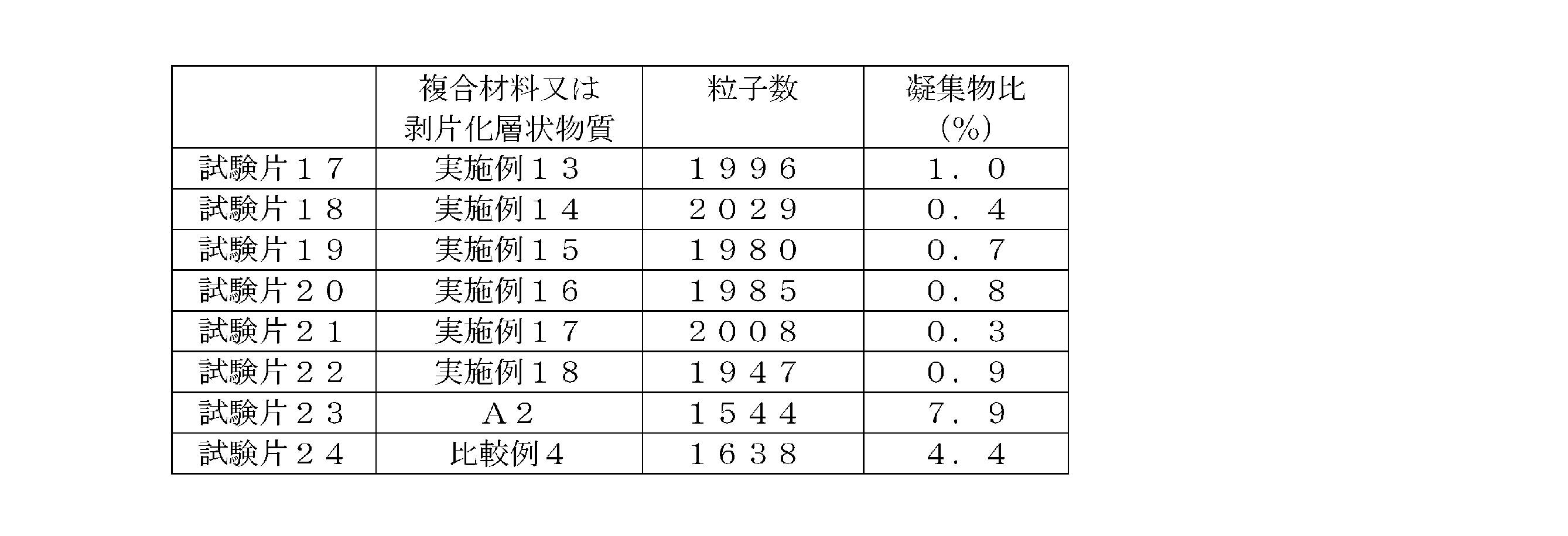
- the test piece was cut using a microtome, the center of the cross section was photographed using a microscope, and the number of particles per 300 ⁇ m ⁇ 300 ⁇ m and the aggregate ratio were measured by image analysis software.
- the aggregate ratio is the ratio (%) of the total area of the aggregates to the total area of the particles when particles having an area of 50 ⁇ m 2 or more are regarded as aggregates.
- Specimens 17 to 22 using the composite materials of Examples 13 to 18 produced by the production method of the present invention were the same as the test piece 23 using the thinned layered substance A2 and Comparative Example 4 produced by another production method. It can be seen that the agglomerate ratio is smaller and the dispersibility of the coating substance is better than that of the test piece 24 used. From these results, it can be seen that according to the production method of the present invention, a composite material having excellent dispersibility can be obtained.
Landscapes
- Chemical & Material Sciences (AREA)
- Organic Chemistry (AREA)
- Life Sciences & Earth Sciences (AREA)
- Engineering & Computer Science (AREA)
- Materials Engineering (AREA)
- Wood Science & Technology (AREA)
- Inorganic Chemistry (AREA)
- General Life Sciences & Earth Sciences (AREA)
- Geology (AREA)
- Compositions Of Macromolecular Compounds (AREA)
- Pigments, Carbon Blacks, Or Wood Stains (AREA)
- Glass Compositions (AREA)
Abstract
Description
即ち、本発明は、剥片化層状物質の表面が被覆物質で被覆された複合材料の製造方法であって、被覆物質を含有する溶液中で剥片化層状物質の二次粒子を解砕する解砕工程1を含む複合材料の製造方法である。また、剥片化層状物質の表面が被覆物質で被覆された複合材料の製造方法であって、溶媒中で剥片化層状物質の二次粒子を解砕する解砕工程2、及び解砕された剥片化層状物質を含む分散液に被覆物質を溶解させる溶解工程を含む複合材料の製造方法である。
〔剥片化層状物質〕
複合材料は剥片化層状物質を含む。層状物質は、共有結合やイオン結合のような強い結合により形成されている単位層が、主に弱いファンデルワールス力を介して積層した層状構造を持つ。層状物質としては、黒鉛類、窒化ホウ素類、遷移金属ジカルコゲナイド、13族カルコゲナイド、14族カルコゲナイド、ビスマスカルコゲナイド、層状ハロゲン化金属、層状遷移金属酸化物、層状ペロブスカイト酸化物、粘土鉱物・層状ケイ酸塩等が挙げられる。層状物質は黒鉛類又は窒化ホウ素類であることが好ましい。
前記複合材料は被覆物質で被覆されたものである。被覆物質は、溶媒に溶解でき、剥片化層状物質の表面に安定な被膜が形成できる有機化合物であれば、特に限定されない。該被覆物質としては、ポリアクリレート、ポリメタクリレート、ポリスチレン、ポリアクリロニトリル、ポリアクリルアミド、ポリ酢酸ビニル、ポリビニルアルコール、ポリビニルアセタール、ポリビニルブチラール、エチレン酢酸ビニルコポリマー、ポリビニルエーテル、ポリビニルピロリドン及びポリビニルアセトアミド等のポリビニル化合物、オレフィンマレイン酸コポリマー、オレフィンフマル酸コポリマー、メチルセルロース、エチルセルロース、アセチルセルロース、カルボキシメチルセルロース、ヒドロキシエチルセルロース、ヒドロキシプロピルセルロース、ポリエチレングリコール、ポリプロピレングリコール、ポリテトラメチレングリコール、ポリシロキサン等の高分子化合物;
ビスフェノールAジグリジジルエーテル及びビスフェノールFジグリジジルエーテル等のビスフェノールのジグリジジルエーテル、フェノールノボラック型エポキシ樹脂、クレゾールノボラック型エポキシ樹脂、3,4-エポキシシクロヘキシルメチル-3,4-エポキシシクロヘキサンカルボキシレート等のエポキシ化合物;
3-エチル-3-[(フェノキシ)メチル]オキセタン、3,7-ビス(3-オキセタニル)-5-オキサ-ノナン等のオキセタン化合物;
2,4-トリレンジイソシアネート、2,6-トリレンジイソシアネート、ジフェニルメタン-4,4’-ジイソシアネート、イソホロンジイソシアネート、ジシクロヘキシルメタン-4,4’-ジイソシアネート、1,6-ヘキサメチレンジイソシアネート等のイソシアネート化合物;
メチルアクリレート、エチルアクリレート、ブチルアクリレート、2-エチルヘキシルアクリレート、ヒドロキシエチルアクリレート、エチレングリコールジアクリレート、プロピレングリコールジアクリレート等のアクリレート化合物;
メチルメタクリレート、エチルメタクリレート、ブチルメタクリレート、2-エチルヘキシルメタクリレート、ドデシルメタクリレート等のメタクリレート化合物;
ブチルビニルエーテル、シクロヘキシルビニルエーテル、ヒドロキシエチルビニルエーテ等のビニルエーテル化合物;
ヘキサン酸ビニル、ネオデカン酸ビニル、安息香酸ビニルのビニルエステル化合物;
メチルトリメトキシシラン、ブチルトリメトキシシラン、フェニルトリメトキシシラン等のアルコキシシラン化合物;
ジブチルヒドロキシトルエン、ブチルヒドロキシアニソール、ステアリル(3,5-ジ-t-ブチル-4-ヒドロキシフェニル)プロピオネート、トリデシルホスファイト、ジラウリルチオジプロピオネート、ジトリデシルチオジプロピオネート、フェニルナフチルアミン、4,4’-ビス(ジアルキル)ジフェニルアミン等の酸化防止剤;
ベンゾトリアゾール系紫外線吸収剤、トリアジン系紫外線吸収剤、シアノアクリレート系紫外線吸収剤の紫外線吸収剤;
2,2,6,6-テトラメチル-4-ピペリジノール脂肪酸エステル等のヒンダードアミン系光安定剤;
テトラブロモビスフェノールA、テトラクロロ無水フタル酸、トリクレジルフォスフェート等の難燃剤;
ジヘプチルフタレート、ジオクチルフタレート、ジオクチルアジペート、ジイソデシルアジペート、ジオクチルセバケート、トリオクチルトリメリテート、テトラオクチルピロメリテート等の可塑剤;
脂肪酸アミド、エチレンビス脂肪酸アミド、金属石鹸、ポリエチレンワックス、モンタンワックス、硬化ひまし油等の滑剤;
アニオン性界面活性剤、ノニオン性界面活性剤、カチオン性界面活性剤、両性界面活性剤等の界面活性剤;
パラフィン系鉱物油、ナフテン系鉱物油、芳香族系鉱物油、ポリブテン、ポリ-α-オレフィン等の炭化水素;
1-ブチル-3-メチルイミダゾリウムビス(トリフルオロメタンスルホニル)イミド、1-ブチル-3-メチルイミダゾリウムジシアンイミド等のイオン液体等が挙げられる。
本発明においては、被覆物質が高分子化合物又はエポキシ化合物であることが好ましい。
前記複合材料における被覆物質の含量は、剥片化層状物質100質量部に対する被覆物質の含量が0.1質量部~100質量部であることが好ましく、0.2質量部~70質量部がより好ましく、0.5質量部~60質量部が更に好ましく、1質量部~50質量部が最も好ましい。
高速回転剪断型撹拌機は、ローターと側面に開口部を有するステーターを有し、ローターが高回転することで剥片化層状物質のスラリーを下部より吸い上げてステーターの側面の開口部より外周部に押出し吐出するタイプの分散装置であり、ローターとステーターの隙間を通過する際、及びステーターの側面の開口部より吐出される際に大きな剪断力が得られる。ローターとステーターの隙間は0.1mm~0.3mm、好ましくは0.15mm~0.2mmであり、ローターの回転数は2,000rpm~15,000rpm、好ましくは3,000rpm~10,000rpmである。高速回転剪断型撹拌機は、高速ホモミキサー又はハイシアミキサー等と呼ばれる場合がある。
容器駆動型ミルは、容器に、剥片化層状物質のスラリー及び粉砕媒体を入れ、容器に回転又は振動を与えて分散する分散機であり、容器と粉砕媒体又は粉砕媒体同士が衝突して剪断力が得られる。容器駆動型ミルには、容器が回転する容器ミル、容器に振動を与える振動ミル、自転する容器に公転回転を加えた遊星ミル等が挙げられる。粉砕媒体は通常、直径0.2mm以上のボール状の粉砕媒体を用いる。容器ミルは、ボール状の粉砕媒体を用いることからボールミルと呼ばれる場合がある。
媒体撹拌ミルは、剥片化層状物質のスラリー及び粉砕媒体を撹拌し粉砕媒体同士が衝突して剪断力が得られる。粉砕媒体としては直径0.03mm~10mm程度のビーズが用いられる。媒体撹拌ミルとしては、サンドミル、アトライター及びビーズミル等が挙げられる。
コロイドミルは、極めて接近した高速回転ディスクと固定ディスクの間に、剥片化層状物質のスラリーを流し込んで分散させる分散機で、ディスク同士により剪断力が得られる。また、中心から外周方向に石臼上に溝が形成されるディスクを用いると、キャビティションが発生して分散性が高められることから好ましい。
高圧乳化機は、剥片化層状物質のスラリーに、少なくとも100MPaの圧力をかけて、細孔を通過させる、細孔から通過させバルブ等の平面やボール等の球面に衝突させる、細孔を通過させた原料を含む液同士を衝突させる等の方法により、急激な圧力の低下や乱流を発生させ、剪断力やキャビティションを発生させて解砕する分散機である。細孔の孔径は、0.05mm~0.5mmが好ましく、0.1mm~0.3mmが更に好ましく、細孔の通過速度は、200m/s~1000m/sが好ましく、400m/s~700m/sが更に好ましい。
超音波乳化機は、剥片化層状物質のスラリーに、超音波を印加して、超音波による剪断力と、気泡発生によるキャビティションにより解砕する分散機である。超音波の周波数は15kHz~40kHz、好ましくは15kHz~25Hzである。
国際公開第2013/172350号パンフレットの実施例1に準じて、天然黒鉛から剥片化層状物質A1を調製した。即ち、1-ブチル-3-メチルイミダゾリウムヘキサフルオロフォスフェート74質量部と、ポリエチレングリコール(富士フイルム和光純薬製、製品名:ポリエチレングリコール20000)26質量部とを混合し加熱溶解し、天然黒鉛(富士フイルム和光純薬製)10質量部を分散させた。この分散液0.6gを0.5cm3のバイアル瓶に採取し、フタをした後、マイクロウェーブ合成装置(バイオタージ・ジャパン製Initiator+)を用いて、分散液に2450MHzのマイクロ波を、170℃で30分照射した。この後、分散液をアセトンで洗浄し、濾過後、オーブンで加熱乾燥することで、天然黒鉛由来の剥片化層状物質A1を得た。剥片化層状物質A1の平均厚さは123nm、平均面積は11.6μm2である。
天然黒鉛の代わりに、窒化ホウ素(アルドリッチ社製)を使用した以外は、製造1と同様の操作を行い、窒化ホウ素由来の剥片化層状物質A2を得た。剥片化層状物質A2の平均厚さは183nm、平均面積は10.3μm2である。
被覆物質として下記のものを用いた。
B1:ビスフェノールA型エポキシ樹脂(一般式(1)のnが0である化合物、株式会社ADEKA製、製品名:アデカレジンEP4100E)
B2:ポリビニルピロリドン(東京化成株式会社製、品名:ポリビニルピロリドン K30)
下記の表1に示す剥片化層状物質スラリーを用いて、複合材料を製造した。なお、表1の( )内の数字は質量比であり、溶媒のMEKはメチルエチルケトンの略である。

高速回転剪断型撹拌機(中央理化製、型式:LZB14-HM-1)を用い、スラリー1を回転数8000rpmで30分処理した後、加熱減圧乾燥させて実施例1の複合材料を得た。
媒体撹拌ミルとしてビーズミル(寿工業製、型式:UAM-015)を用い、スラリー1を5回通液させた後、加熱減圧乾燥させて実施例2の複合材料を得た。なお、分散媒体として直径0.1mmのジルコニアビーズを、スラリー1に対して2倍量用いた。
容器駆動型ミルとして、遊星ミル(株式会社EME製、型式:V-mini300)を用い、スラリー1を30分処理した後、加熱減圧乾燥させて実施例3の複合材料を得た。なお、分散媒体として直径5mmのアルミナビーズを、スラリー1に対して等量用いた。
コロイドミル(増幸産業製、型式:スーパーマスコロイダーMKCA6-2)を用い、スラリー1を5回通液させた後、加熱減圧乾燥させて実施例4の複合材料を得た。なお、使用したコロイドミルのディスクの直径は150mmで、回転ディスクの回転数は2000rpmであった。
高圧乳化機(吉田機械興業社製、型式:YSナノマイザー)を用い、細孔107μmの貫通型ジェネレータに圧力2MPaでスラリー1を3回通液させた後、加熱減圧乾燥させて実施例5の複合材料を得た。
超音波乳化機(株式会社トミー精工製、型式:UD-201)を用い、200gのスラリー1に周波数20kHzの超音波を20分照射した後、加熱減圧乾燥させて実施例6の複合材料を得た。
スラリー2を用いた以外は、実施例1と同様の操作を行い実施例7の複合材料を得た。
実施例8:媒体撹拌ミル
スラリー2を用いた以外は、実施例2と同様の操作を行い実施例8の複合材料を得た。
実施例9:容器駆動型ミル
スラリー2を用いた以外は、実施例3と同様の操作を行い実施例9の複合材料を得た。
実施例10:コロイドミル
スラリー2を用いた以外は、実施例4と同様の操作を行い実施例10の複合材料を得た。
実施例11:高圧乳化機
スラリー2を用いた以外は、実施例5と同様の操作を行い実施例11の複合材料を得た。
実施例12:超音波乳化機
スラリー2を用いた以外は、実施例6と同様の操作を行い実施例12の複合材料を得た。
スラリー3を用いた以外は、実施例1と同様の操作を行い実施例13の複合材料を得た。
実施例14:媒体撹拌ミル
スラリー3を用いた以外は、実施例2と同様の操作を行い実施例14の複合材料を得た。
実施例15:容器駆動型ミル
スラリー3を用いた以外は、実施例3と同様の操作を行い実施例15の複合材料を得た。
実施例16:コロイドミル
スラリー3を用いた以外は、実施例4と同様の操作を行い実施例16の複合材料を得た。
実施例17:高圧乳化機
スラリー3を用いた以外は、実施例5と同様の操作を行い実施例17の複合材料を得た。
実施例18:超音波乳化機
スラリー3を用いた以外は、実施例6と同様の操作を行い実施例18の複合材料を得た。
撹拌子を用いてスラリー1を30分撹拌した後、加熱減圧乾燥させて比較例1の複合材料を得た。
比較例2
スラリー2を用いた以外は、比較例1と同様の操作を行い比較例2の複合材料を得た。
比較例3
撹拌子を用いてスラリー2を30分撹拌した後、入口温度180℃、出口温度75℃の条件で噴霧乾燥し、比較例3の複合材料を得た。
比較例4
スラリー3を用いた以外は、比較例1と同様の操作を行い比較例4の複合材料を得た。
ポリプロピレン(ホモポリマー、メルトフローレート:8g/10min)100部と表2に示す複合材料又は剥片化層状物質2部を二軸混錬機を用いて230℃で混錬して押出し、太さ4mmの樹脂ストランドを作製した。
試験片をミクロトームを用いて切断し、走査型電子顕微鏡を用いて断面の中央部を撮影し、画像解析ソフトにより、300μm×300μmあたりの粒子数と、凝集物比を測定した。なお、凝集物比は、面積40μm2以上の粒子を凝集物とした場合の、粒子の面積の合計に対する凝集物の面積の合計の比(%)である。粒子数が多いほど分散性が良好であり、凝集物比が大きいほど凝集物の割合が多いことを示す。結果を表2に示す。
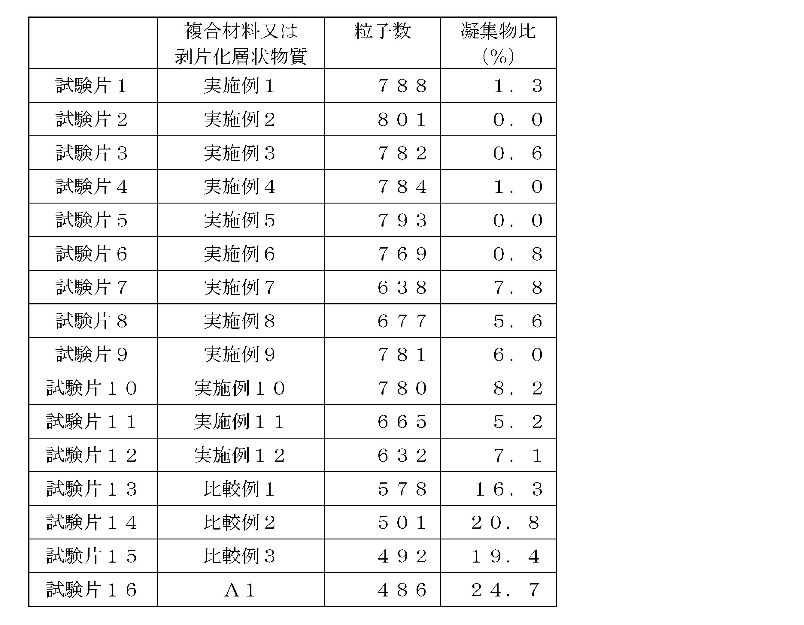
表3に示す複合材料又は剥片化層状物質20質量、ビスフェノールA型エポキシ樹脂(株式会社ADEKA製、製品名:アデカレジンEP4100E)100質量部及びイミダゾール系触媒(1-ベンジル-2-メチルイミダゾール)0.5質量部を、遊星式撹拌脱泡装置を用いて混合した。この混合物を温度160℃、圧力5MPaで1時間加熱し、熱プレス硬化させて厚さ3mmのシートを作成した。このシートを50mm四方の正方形に切断し試験片を準備した。
試験片をミクロトームを用いて切断し、マイクロスコープを用いて断面の中央部を撮影し、画像解析ソフトにより、300μm×300μmあたりの粒子数と、凝集物比を測定した。なお、凝集物比は、面積50μm2以上の粒子を凝集物とした場合の、粒子の面積の合計に対する凝集物の面積の合計の比(%)である。粒子数が多いほど分散性が良好であり、凝集物比が大きいほど凝集物の割合が多いことを示す。結果を表3に示す。
Claims (16)
- 剥片化層状物質の表面が被覆物質で被覆された複合材料の製造方法であって、
被覆物質を含有する溶液中で剥片化層状物質の二次粒子を解砕する解砕工程を含む複合材料の製造方法。 - 剥片化層状物質の表面が被覆物質で被覆された複合材料の製造方法であって、
溶媒中で剥片化層状物質の二次粒子を解砕する解砕工程、及び
解砕された剥片化層状物質を含む分散液に被覆物質を溶解させる溶解工程を含む複合材料の製造方法。 - 剥片化層状物質の二次粒子の解砕を、高速回転剪断型撹拌機、媒体撹拌ミル、容器駆動型ミル、コロイドミル、高圧乳化機及び超音波乳化機からなる群から選択される分散機を使用して行う、請求項1又は2記載の複合材料の製造方法。
- 剥片化層状物質の二次粒子の解砕を高速回転剪断型撹拌機を使用して行う、請求項3に記載の複合材料の製造方法。
- 剥片化層状物質の二次粒子の解砕を媒体撹拌ミルを使用して行う、請求項3記載の複合材料の製造方法。
- 剥片化層状物質の二次粒子の解砕を容器駆動型ミルを使用して行う、請求項3記載の複合材料の製造方法。
- 剥片化層状物質の二次粒子の解砕をコロイドミルを使用して行う、請求項3記載の複合材料の製造方法。
- 剥片化層状物質の二次粒子の解砕を高圧乳化機を使用して行う、請求項3記載の複合材料の製造方法。
- 剥片化層状物質の二次粒子の解砕を超音波乳化機を使用して行う、請求項3記載の複合材料の製造方法。
- 複合材料の剥片化層状物質100質量部に対する被覆物質の含量が0.1質量部~100質量部である、請求項1~9のいずれか1項に記載の複合材料の製造方法。
- 剥片化層状物質の平均厚さが1200nm以下であり、剥片化層状物質の平均面積が0.1μm2~500μm2である、請求項1~10のいずれか1項に記載の複合材料の製造方法。
- 剥片化層状物質が黒鉛類又は窒化ホウ素類に由来する、請求項1~11のいずれか1項に記載の複合材料の製造方法。
- 前記黒鉛類が天然黒鉛である、請求項12に記載の複合材料の製造方法。
- 被覆物質がエポキシ化合物又は高分子化合物である、請求項1~13のいずれか1項に記載の複合材料の製造方法。
- 前記エポキシ化合物がビスフェノールのジグリシジルエーテルである、請求項14に記載の複合材料の製造方法。
- 前記高分子化合物がポリビニル化合物である、請求項14に記載の複合材料の製造方法。
Priority Applications (5)
| Application Number | Priority Date | Filing Date | Title |
|---|---|---|---|
| CN201980047392.8A CN112424293B (zh) | 2018-07-30 | 2019-07-29 | 复合材料的制造方法 |
| KR1020217000455A KR102710156B1 (ko) | 2018-07-30 | 2019-07-29 | 복합 재료의 제조 방법 |
| US17/260,471 US12173164B2 (en) | 2018-07-30 | 2019-07-29 | Method for producing composite material |
| JP2020533530A JP7407711B2 (ja) | 2018-07-30 | 2019-07-29 | 複合材料の製造方法 |
| EP19845223.7A EP3831892A4 (en) | 2018-07-30 | 2019-07-29 | PROCESS FOR MAKING A COMPOSITE |
Applications Claiming Priority (2)
| Application Number | Priority Date | Filing Date | Title |
|---|---|---|---|
| JP2018-142984 | 2018-07-30 | ||
| JP2018142984 | 2018-07-30 |
Publications (1)
| Publication Number | Publication Date |
|---|---|
| WO2020027041A1 true WO2020027041A1 (ja) | 2020-02-06 |
Family
ID=69232135
Family Applications (1)
| Application Number | Title | Priority Date | Filing Date |
|---|---|---|---|
| PCT/JP2019/029632 Ceased WO2020027041A1 (ja) | 2018-07-30 | 2019-07-29 | 複合材料の製造方法 |
Country Status (7)
| Country | Link |
|---|---|
| US (1) | US12173164B2 (ja) |
| EP (1) | EP3831892A4 (ja) |
| JP (1) | JP7407711B2 (ja) |
| KR (1) | KR102710156B1 (ja) |
| CN (1) | CN112424293B (ja) |
| TW (1) | TWI821345B (ja) |
| WO (1) | WO2020027041A1 (ja) |
Cited By (1)
| Publication number | Priority date | Publication date | Assignee | Title |
|---|---|---|---|---|
| JPWO2024106404A1 (ja) * | 2022-11-14 | 2024-05-23 |
Citations (16)
| Publication number | Priority date | Publication date | Assignee | Title |
|---|---|---|---|---|
| JPS5956435A (ja) * | 1982-08-20 | 1984-03-31 | チバ−ガイギ−・アクチエンゲゼルシヤフト | グラフアイトを含有する新規組成物 |
| JPS59156903A (ja) * | 1983-02-25 | 1984-09-06 | Shin Etsu Chem Co Ltd | 水分散液形成性炭素粉末の製造方法 |
| US20120301707A1 (en) | 2010-01-18 | 2012-11-29 | Ian Anthony Kinloch | Graphene polymer composite |
| JP2012240891A (ja) * | 2011-05-20 | 2012-12-10 | Vision Development Co Ltd | ナノカーボン・ナノコンポジット及びその製造方法 |
| US20130296479A1 (en) | 2012-05-03 | 2013-11-07 | Ppg Industries Ohio, Inc. | Rubber formulations including graphenic carbon particles |
| WO2013172350A1 (ja) | 2012-05-14 | 2013-11-21 | 国立大学法人 東京大学 | 新規グラフェンナノ分散液及びその調製方法 |
| US20140272350A1 (en) | 2011-10-28 | 2014-09-18 | Cheil Industries Inc. | Gas barrier film including graphene layer, flexible substrate including the same, and manufacturing method thereof |
| US20160101980A1 (en) | 2014-09-09 | 2016-04-14 | Graphene Platform Corporation | Graphite-based carbon material useful as graphene precursor, as well as method of producing the same |
| JP2016060887A (ja) | 2014-09-19 | 2016-04-25 | 康博 青木 | 発電性組成物及びこれを用いた発電素子、発電装置及び蓄発電装置 |
| WO2016088682A1 (ja) * | 2014-12-02 | 2016-06-09 | 積水化学工業株式会社 | 熱伝導シート及びその製造方法 |
| US20160200580A1 (en) | 2015-01-12 | 2016-07-14 | Ningbo Morsh Technology Co., Ltd. | Graphene composite powder form material and method for making the same |
| JP2016531824A (ja) | 2014-04-28 | 2016-10-13 | 寧波墨西科技有限公司Ningbo Morsh Technology CO., LTD. | グラフェン複合粉体材料及びその製造方法 |
| CN107381643A (zh) * | 2016-12-12 | 2017-11-24 | 广东纳路纳米科技有限公司 | 一种机械剥离范德华层状材料制备二维材料的通用方法 |
| JP2018070412A (ja) * | 2016-10-28 | 2018-05-10 | 株式会社ダイセル | ナノダイヤモンド分散液製造方法およびナノダイヤモンド分散液 |
| US20180186954A1 (en) | 2015-01-14 | 2018-07-05 | Nitto Denko Corporation | Graphene oxide barrier film |
| JP2018177549A (ja) * | 2017-04-04 | 2018-11-15 | 日立化成株式会社 | 薄層化黒鉛複合体 |
Family Cites Families (7)
| Publication number | Priority date | Publication date | Assignee | Title |
|---|---|---|---|---|
| JP5933374B2 (ja) * | 2012-07-03 | 2016-06-08 | ハリマ化成株式会社 | 薄層黒鉛または薄層黒鉛化合物の製造方法 |
| US20170095784A1 (en) | 2014-04-17 | 2017-04-06 | Adeka Corporation | Layered substance-containing liquid and method for producing same |
| JP6522326B2 (ja) | 2014-12-10 | 2019-05-29 | 株式会社豊田自動織機 | 黒鉛粒子組成物およびその製造方法、負極ならびに蓄電装置 |
| EP3266745A4 (en) * | 2015-03-05 | 2019-01-23 | Hitachi Chemical Company, Ltd. | COMPLEX BETWEEN AN INORGANIC LAMELLAR COMPOUND AND ORGANIC COMPOUND AND METHOD FOR THE PRODUCTION THEREOF, EXCLUSIVE LAMELLAR INORGANIC COMPOUND AND METHOD FOR THE MANUFACTURE THEREOF, INSULATING RESIN COMPOSITION, RESIN FOIL, ISOLATOR, CURED ARTICLE OF RESIN FOIL AND HEAT DISPOSING ELEMENT |
| JP2017141345A (ja) * | 2016-02-10 | 2017-08-17 | 日本ゼオン株式会社 | 複合材料シートおよび熱伝導シートの製造方法 |
| CN105800579B (zh) | 2016-03-07 | 2019-01-18 | 南方科技大学 | 一种层状纳米颗粒、剥离方法及应用 |
| CN107200947B (zh) | 2017-05-22 | 2019-08-20 | 成都新柯力化工科技有限公司 | 一种石墨烯微片导电母料及其制备方法 |
-
2019
- 2019-07-29 EP EP19845223.7A patent/EP3831892A4/en active Pending
- 2019-07-29 JP JP2020533530A patent/JP7407711B2/ja active Active
- 2019-07-29 CN CN201980047392.8A patent/CN112424293B/zh active Active
- 2019-07-29 KR KR1020217000455A patent/KR102710156B1/ko active Active
- 2019-07-29 US US17/260,471 patent/US12173164B2/en active Active
- 2019-07-29 WO PCT/JP2019/029632 patent/WO2020027041A1/ja not_active Ceased
- 2019-07-30 TW TW108126880A patent/TWI821345B/zh active
Patent Citations (16)
| Publication number | Priority date | Publication date | Assignee | Title |
|---|---|---|---|---|
| JPS5956435A (ja) * | 1982-08-20 | 1984-03-31 | チバ−ガイギ−・アクチエンゲゼルシヤフト | グラフアイトを含有する新規組成物 |
| JPS59156903A (ja) * | 1983-02-25 | 1984-09-06 | Shin Etsu Chem Co Ltd | 水分散液形成性炭素粉末の製造方法 |
| US20120301707A1 (en) | 2010-01-18 | 2012-11-29 | Ian Anthony Kinloch | Graphene polymer composite |
| JP2012240891A (ja) * | 2011-05-20 | 2012-12-10 | Vision Development Co Ltd | ナノカーボン・ナノコンポジット及びその製造方法 |
| US20140272350A1 (en) | 2011-10-28 | 2014-09-18 | Cheil Industries Inc. | Gas barrier film including graphene layer, flexible substrate including the same, and manufacturing method thereof |
| US20130296479A1 (en) | 2012-05-03 | 2013-11-07 | Ppg Industries Ohio, Inc. | Rubber formulations including graphenic carbon particles |
| WO2013172350A1 (ja) | 2012-05-14 | 2013-11-21 | 国立大学法人 東京大学 | 新規グラフェンナノ分散液及びその調製方法 |
| JP2016531824A (ja) | 2014-04-28 | 2016-10-13 | 寧波墨西科技有限公司Ningbo Morsh Technology CO., LTD. | グラフェン複合粉体材料及びその製造方法 |
| US20160101980A1 (en) | 2014-09-09 | 2016-04-14 | Graphene Platform Corporation | Graphite-based carbon material useful as graphene precursor, as well as method of producing the same |
| JP2016060887A (ja) | 2014-09-19 | 2016-04-25 | 康博 青木 | 発電性組成物及びこれを用いた発電素子、発電装置及び蓄発電装置 |
| WO2016088682A1 (ja) * | 2014-12-02 | 2016-06-09 | 積水化学工業株式会社 | 熱伝導シート及びその製造方法 |
| US20160200580A1 (en) | 2015-01-12 | 2016-07-14 | Ningbo Morsh Technology Co., Ltd. | Graphene composite powder form material and method for making the same |
| US20180186954A1 (en) | 2015-01-14 | 2018-07-05 | Nitto Denko Corporation | Graphene oxide barrier film |
| JP2018070412A (ja) * | 2016-10-28 | 2018-05-10 | 株式会社ダイセル | ナノダイヤモンド分散液製造方法およびナノダイヤモンド分散液 |
| CN107381643A (zh) * | 2016-12-12 | 2017-11-24 | 广东纳路纳米科技有限公司 | 一种机械剥离范德华层状材料制备二维材料的通用方法 |
| JP2018177549A (ja) * | 2017-04-04 | 2018-11-15 | 日立化成株式会社 | 薄層化黒鉛複合体 |
Non-Patent Citations (1)
| Title |
|---|
| See also references of EP3831892A4 |
Cited By (2)
| Publication number | Priority date | Publication date | Assignee | Title |
|---|---|---|---|---|
| JPWO2024106404A1 (ja) * | 2022-11-14 | 2024-05-23 | ||
| WO2024106404A1 (ja) * | 2022-11-14 | 2024-05-23 | デンカ株式会社 | 球状窒化ホウ素粉末、樹脂用充填剤、樹脂組成物及び球状窒化ホウ素粉末の製造方法 |
Also Published As
| Publication number | Publication date |
|---|---|
| JP7407711B2 (ja) | 2024-01-04 |
| CN112424293A (zh) | 2021-02-26 |
| EP3831892A1 (en) | 2021-06-09 |
| JPWO2020027041A1 (ja) | 2021-08-02 |
| EP3831892A4 (en) | 2022-05-11 |
| KR20210039370A (ko) | 2021-04-09 |
| US12173164B2 (en) | 2024-12-24 |
| TWI821345B (zh) | 2023-11-11 |
| CN112424293B (zh) | 2022-07-19 |
| TW202020065A (zh) | 2020-06-01 |
| US20210269650A1 (en) | 2021-09-02 |
| KR102710156B1 (ko) | 2024-09-26 |
Similar Documents
| Publication | Publication Date | Title |
|---|---|---|
| Jouault et al. | Role of casting solvent on nanoparticle dispersion in polymer nanocomposites | |
| Aubry et al. | Rheological investigation of the melt state elastic and yield properties of a polyamide-12 layered silicate nanocomposite | |
| Sun et al. | Effect of nanoplatelets on the rheological behavior of epoxy monomers | |
| Filippone et al. | Viscoelasticity and structure of polystyrene/fumed silica nanocomposites: filler network and hydrodynamic contributions | |
| Wang et al. | Unusual rheological behavior of liquid polybutadiene rubber/clay nanocomposite gels: the role of polymer− clay interaction, clay exfoliation, and clay orientation and disorientation | |
| KR102778379B1 (ko) | 복합 재료 | |
| Pavithra et al. | Synthesis, characterisation and thermal conductivity of CuO-water based nanofluids with different dispersants | |
| KR101854026B1 (ko) | 질화보론 나노시트 분말의 제조방법 및 이를 이용한 질화보론 나노시트/폴리머 나노복합필름의 제조방법 | |
| JP4841987B2 (ja) | フレーク銀粉及びその製造方法 | |
| JP2017141345A (ja) | 複合材料シートおよび熱伝導シートの製造方法 | |
| Hermida-Merino et al. | Evidence of viscoplastic behavior of exfoliated graphite nanofluids | |
| JP7407711B2 (ja) | 複合材料の製造方法 | |
| TW202233519A (zh) | 氮化硼材料、含有該氮化硼材料之樹脂組成物及絕緣材料 | |
| Wang et al. | Correlations of surface free energy and solubility parameter with dielectric constant and density for inorganic solids | |
| Guan et al. | The surface modification of BaTiO3 and its effects on the microstructure and electrical properties of BaTiO3/silicone rubber composites | |
| Prusty et al. | h‐BN huddled starch reinforced polyethylhexylacrylate\polyvinyl alcohol thin films for packaging applications | |
| KR102747045B1 (ko) | 복합 재료 | |
| Sajjadi Jazi et al. | Investigation of the addition of nano‐CaCO3 at dry mixing or onset of fusion on the dispersion, torque, and mechanical properties of compounded PVC | |
| Beuguel et al. | Elaboration and relationships between structure and rheological properties of microtalc or nanotalc/polyamide composites | |
| Shimpi et al. | Optimized Synthesis of nTiO2 using murraya koenigii leaf extract and its application in iPP–EPDM blends | |
| Xu et al. | Rheology of a low‐filled polyamide 6/montmorillonite nanocomposite | |
| Shao et al. | Polyamide‐6/natural clay mineral nanocomposites prepared by solid‐state shear milling using pan‐mill equipment | |
| JP7570194B2 (ja) | 薄片化黒鉛及び樹脂組成物 | |
| Potarniche et al. | Influence of two compatibilizers on clay/PP nanocomposites properties | |
| JP2010120824A (ja) | 軟凝集粉末、及び無機粒子−有機ポリマー複合ペースト |
Legal Events
| Date | Code | Title | Description |
|---|---|---|---|
| 121 | Ep: the epo has been informed by wipo that ep was designated in this application |
Ref document number: 19845223 Country of ref document: EP Kind code of ref document: A1 |
|
| ENP | Entry into the national phase |
Ref document number: 20217000455 Country of ref document: KR Kind code of ref document: A |
|
| ENP | Entry into the national phase |
Ref document number: 2020533530 Country of ref document: JP Kind code of ref document: A |
|
| NENP | Non-entry into the national phase |
Ref country code: DE |
|
| ENP | Entry into the national phase |
Ref document number: 2019845223 Country of ref document: EP Effective date: 20210301 |