WO2020027059A1 - Élément de vis mâle, élément de vis femelle, et structure de fixation à vis - Google Patents
Élément de vis mâle, élément de vis femelle, et structure de fixation à vis Download PDFInfo
- Publication number
- WO2020027059A1 WO2020027059A1 PCT/JP2019/029679 JP2019029679W WO2020027059A1 WO 2020027059 A1 WO2020027059 A1 WO 2020027059A1 JP 2019029679 W JP2019029679 W JP 2019029679W WO 2020027059 A1 WO2020027059 A1 WO 2020027059A1
- Authority
- WO
- WIPO (PCT)
- Prior art keywords
- line
- respect
- screw member
- valley bottom
- peak
- Prior art date
- Legal status (The legal status is an assumption and is not a legal conclusion. Google has not performed a legal analysis and makes no representation as to the accuracy of the status listed.)
- Ceased
Links
Images








Classifications
-
- F—MECHANICAL ENGINEERING; LIGHTING; HEATING; WEAPONS; BLASTING
- F16—ENGINEERING ELEMENTS AND UNITS; GENERAL MEASURES FOR PRODUCING AND MAINTAINING EFFECTIVE FUNCTIONING OF MACHINES OR INSTALLATIONS; THERMAL INSULATION IN GENERAL
- F16B—DEVICES FOR FASTENING OR SECURING CONSTRUCTIONAL ELEMENTS OR MACHINE PARTS TOGETHER, e.g. NAILS, BOLTS, CIRCLIPS, CLAMPS, CLIPS OR WEDGES; JOINTS OR JOINTING
- F16B33/00—Features common to bolt and nut
- F16B33/02—Shape of thread; Special thread-forms
-
- F—MECHANICAL ENGINEERING; LIGHTING; HEATING; WEAPONS; BLASTING
- F16—ENGINEERING ELEMENTS AND UNITS; GENERAL MEASURES FOR PRODUCING AND MAINTAINING EFFECTIVE FUNCTIONING OF MACHINES OR INSTALLATIONS; THERMAL INSULATION IN GENERAL
- F16B—DEVICES FOR FASTENING OR SECURING CONSTRUCTIONAL ELEMENTS OR MACHINE PARTS TOGETHER, e.g. NAILS, BOLTS, CIRCLIPS, CLAMPS, CLIPS OR WEDGES; JOINTS OR JOINTING
- F16B35/00—Screw-bolts; Stay-bolts; Screw-threaded studs; Screws; Set screws
-
- F—MECHANICAL ENGINEERING; LIGHTING; HEATING; WEAPONS; BLASTING
- F16—ENGINEERING ELEMENTS AND UNITS; GENERAL MEASURES FOR PRODUCING AND MAINTAINING EFFECTIVE FUNCTIONING OF MACHINES OR INSTALLATIONS; THERMAL INSULATION IN GENERAL
- F16L—PIPES; JOINTS OR FITTINGS FOR PIPES; SUPPORTS FOR PIPES, CABLES OR PROTECTIVE TUBING; MEANS FOR THERMAL INSULATION IN GENERAL
- F16L15/00—Screw-threaded joints; Forms of screw-threads for such joints
-
- F—MECHANICAL ENGINEERING; LIGHTING; HEATING; WEAPONS; BLASTING
- F16—ENGINEERING ELEMENTS AND UNITS; GENERAL MEASURES FOR PRODUCING AND MAINTAINING EFFECTIVE FUNCTIONING OF MACHINES OR INSTALLATIONS; THERMAL INSULATION IN GENERAL
- F16L—PIPES; JOINTS OR FITTINGS FOR PIPES; SUPPORTS FOR PIPES, CABLES OR PROTECTIVE TUBING; MEANS FOR THERMAL INSULATION IN GENERAL
- F16L15/00—Screw-threaded joints; Forms of screw-threads for such joints
- F16L15/06—Screw-threaded joints; Forms of screw-threads for such joints characterised by the shape of the screw-thread
Definitions
- the present invention relates to a male screw member, a female screw member, and a screw fastening structure.
- a male screw member having a male screw portion made of a tapered male screw is screwed into a female screw member having a female screw portion made of a tapered female screw or a parallel female screw (for example, Patent Document 1). ).
- the outer diameter and the root diameter on the tip side of the tapered male screw are set to be somewhat smaller than the root diameter and the inner diameter on the open end side of the tapered female screw or the parallel female screw, respectively. Therefore, shortly after screwing is started, there is a large gap between the external thread and the internal thread, so that the axis of the external thread is inclined with respect to the axis of the internal thread. (Hereinafter referred to as “diagonal screwing”).
- the diagonal screwing is more likely to occur mainly when one of the male screw member and the female screw member is made of resin and the other is made of metal, because the difference in strength between the two becomes large.
- the male screw member of the present invention is: A male screw member having a screw portion on an outer peripheral surface, In a cross section including the axis of the external thread member,
- the peak line of the external thread portion is, at least in part, a peak line portion connecting a pair of peaks adjacent to each other, and another peak line portion adjacent to the root side of the external thread member with respect to the peak line portion.
- Located on the outer peripheral side of the extension from and / or The root line of the external thread portion is, at least in part, a root line portion connecting a pair of adjacent roots to each other, and another root line portion adjacent to the root side of the external thread member with respect to the root line portion. It is located on the outer peripheral side of the extension from.
- the female screw member of the present invention A female screw member having a female screw portion on an inner peripheral surface, In a cross section including the axis of the female screw member,
- the top line of the female thread portion is, at least in part, a top line portion connecting a pair of peaks adjacent to each other, and another top line portion adjacent to the back side of the female screw member with respect to the top line portion.
- Located on the inner circumference side from the extension line from and / or The root line of the female thread portion is, at least in part, a root line portion connecting a pair of adjacent roots to each other, and another root line portion adjacent to the depth side of the internal thread member with respect to the root line portion. It is located on the inner peripheral side of the extension from.
- the screw fastening structure of the present invention With the above male screw member, An internal thread member having an internal thread portion on the inner peripheral surface, With One of the external thread member and the internal thread member is made of a resin material, The other of the external thread member and the internal thread member is made of a metal material, The male thread portion of the male thread member is screwed into the female thread portion of the female thread member.
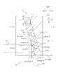
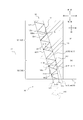
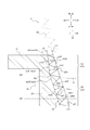
- FIG. 4 is a partial cross-sectional side view schematically showing the male screw member according to the first embodiment of the present invention, together with a female screw member having a female screw portion formed of a conventional tapered female screw.
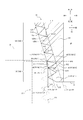
- FIG. 2 is an axial cross-sectional view schematically showing an enlarged external thread member of FIG. 1.
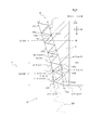
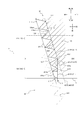
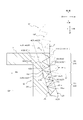
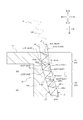
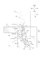
- FIG. 2 is an axial cross-sectional view schematically showing an enlarged external thread member of FIG. 1. It is an axial sectional view which expands and shows roughly some external thread members which concern on 2nd Embodiment of this invention. It is an axial direction sectional view which expands and shows roughly a part of external thread member concerning a 3rd embodiment of the present invention.
- FIG. 15 is an axial cross-sectional view schematically showing an enlarged part of a male screw member according to a sixth embodiment of the present invention. It is an axial section view which expands and shows roughly a part of male thread member concerning a 7th embodiment of the present invention.
- FIG. 2 is an axial cross-sectional view schematically showing an enlarged part of the female screw member according to the first embodiment of the present invention.
- the external thread member of the present invention can be suitably applied to a tubular member (for example, a pipe joint) or a solid member used in any field and application, and is particularly suitably used for a tubular member used in any field and application. It is applicable to, for example, a tubular member used for water supply / hot water supply piping.
- the female screw member of the present invention can be suitably applied to a tubular member (for example, a pipe joint) used in any field and application, and can be suitably applied to, for example, a tubular member used for water supply / hot water supply piping. It is.
- a male screw member, a female screw member, and a screw fastening structure according to the present invention will be described with reference to the drawings.
- the shape of the thread in the cross section including the axis of the external thread member or the internal thread member is a triangular shape having a square shape for simplicity, but includes the axis of the external thread member or the internal thread member.
- the shape of the thread in the cross section may be any shape such as a rounded triangle without trapezoids, a trapezoid, or the like.
- FIGS. 1-3 in addition to the threaded member 10 of this embodiment, for reference, a female threaded member 20 '(in FIG. 1) suitable for use with the threaded member 10 of this embodiment. Solid lines, and broken lines in FIGS. 2 and 3) are also shown. 1, the left side of FIG. 1 shows a cross section including the axis O of the threaded member 10 and the internal threaded member 20 'of the present embodiment, and the right side of FIG. 1 shows these side surfaces.
- FIG. 2 is an enlarged view of a part of each of the male screw member 10 and the female screw member 20 ′ in FIG. In FIGS.
- FIG. 3 is a view similar to FIG. 2, but differs from FIG. 2 in that the internal thread portion 220 ′ of the internal thread member 20 ′ is a parallel internal thread.
- the “axial direction” of the male screw member (10, 10 ′) or the female screw member (20, 20 ′) refers to the male screw member (10, 10 ′) or the female screw member (20, 20 ′).
- 20 ′) refers to a direction parallel to the axis (center axis) (O, O ′).
- the “tips (11, 11 ′)” of the male screw member (10, 10 ′) refer to the female screw member (10, 10 ′) of the two axial ends of the male screw member (10, 10 ′).
- 20, 20 ') (the end of the tube in the illustrated example).
- the “tip side” of the male screw member (10, 10 ′) refers to the tip (11, 11 ′) of the male screw member (10, 10 ′) in the axial direction of the male screw member (10, 10 ′). Pointing to the side.
- the “root side” of the male screw member (10, 10 ′) refers to the tip (11, 11 ′) side of the male screw member (10, 10 ′) in the axial direction of the male screw member (10, 10 ′). Indicates the opposite side.
- the “open ends (21, 21 ′)” of the female screw members (20, 20 ′) are defined as the male screw members among the axial ends of the female screw members (20, 20 ′).
- the male screw members (10, 10 ') and the female screw members (20, 20') are arranged coaxially. In each of FIGS.
- the axial direction is indicated by an arrow AD
- the radial direction is indicated by an arrow RD
- the inner peripheral side (the side approaching the axis O) is indicated by an arrow IR
- the outer peripheral side (the side away from the axis O) ) Is indicated by an arrow OR
- the tip (11, 11 ′) side of the male screw member (10, 10 ′) is indicated by an arrow TE
- the root side of the male screw member (10, 10 ′) is indicated by an arrow RE.
- the open end (21, 21 ') side of the screw member (20, 20') is indicated by an arrow OE
- the far side of the female screw member (20, 20 ') is indicated by an arrow BE.
- the threaded member 10 of the first embodiment shown in FIGS. 1 to 3 is made of a resin material and has a main body 110 and a male thread 120 provided on the outer peripheral surface of the main body 110. ing. Since the screw member 10 of the present embodiment is made of a resin material, the weight can be reduced. However, the male screw member 10 may be made of a metal material.
- the external thread member 10 of the present embodiment is configured in a tubular shape, and is configured as, for example, a pipe joint configured to be connected to another tubular member. However, the male screw member 10 may be configured as a solid member. As shown in FIG.
- the male screw portion 120 in a cross section including the axis O of the male screw member 10, has a tapered portion 121 and a distal end side portion 122 that is continuous from the tapered portion 121 to the distal end 11 side TE. are doing.
- the tapered portion 121 is configured such that the top line L11 and the bottom line L12 of the male screw portion 120 are parallel to each other, and are directed toward the inner peripheral side IR toward the distal end 11 side TE of the male screw member 10, respectively. It is inclined at a fixed angle ( ⁇ 111, ⁇ 121) with respect to the ten axis directions. Accordingly, the outer diameter and the valley diameter of the tapered portion 121 gradually decrease toward the front end 11 side TE. It is preferable that the tapered portion 121 has a configuration of a tapered male thread specified in JIS B 0203. In other words, the tapered portion 121 has a configuration in the axial direction region corresponding to the tapered portion 121 of the male screw portion 120 when the entire screw portion 120 is a tapered male screw specified in JIS B0203. It is suitable to have.
- the “crest line (L11, L11 ′)” of the male screw portion (120, 120 ′) is a cross section including the axis (O, O ′) of the male screw member (10, 10 ′). Is a virtual line formed by connecting the crests (crests) (120cr) of the screw threads (120ri) adjacent to each other of the male screw portions (120, 120 ') with straight lines.
- peak lines (L11, L11 ') of the male thread portions (120, 120') a portion formed by connecting a pair of adjacent peaks (120cr) with a straight line is referred to as a "peak line portion (uL11)".
- the peak line (L11, L11 ′) includes a plurality of peak line portions (uL11).
- the peak line (L11, L11 ′) extends on the peak (120cr) at a position corresponding to the peak (120cr), and a portion between the peaks (120cr) is connected by a straight line to form a peak line portion (uL11).
- the “bottom line (L12, L12 ′)” of the male screw part (120, 120 ′) is a cross section including the axis (O, O ′) of the male screw member (10, 10 ′).
- 120 ′) are virtual lines formed by connecting straight lines between the roots (120ro) of adjacent screw threads (120ri).
- valley bottom lines (L12, L12 ') of the external thread portions (120, 120') a portion formed by connecting a pair of adjacent valley bottoms (120ro) with a straight line is referred to as a "valley bottom line portion (uL12)".
- the bottom line (L12, L12 ′) includes a plurality of bottom line portions (uL12).
- the valley bottom line (L12, L12 ') becomes the valley bottom (120ro).
- the valley bottom line (L12, L12 ') becomes the valley bottom (120ro).
- the valley bottom line (L12, L12 ') becomes the valley bottom (120ro).
- the valley bottom line (uL12) Extends over the valley bottom (120ro), and the portion between the valley bottoms (120ro) is connected by a straight line to form a valley bottom line portion (uL12).
- the “outer diameter” of the male screw portion (120, 120 ′) is determined from the peak line (L11, L11 ′) of the male screw portion (120, 120 ′) to the axis (O) of the male screw member (10, 10 ′).
- the “trough diameter” of the male screw part (120, 120 ′) is from the root line (L12, L12 ′) of the male screw part (120, 120 ′) to the axis (O, O) of the male screw member (10, 10 ′). Double the radial distance to ').
- the “crest line (L21, L21 ′)” of the female screw portion (220, 220 ′) is a cross section including the axis (O, O ′) of the female screw member (20, 20 ′).
- the imaginary line is formed by connecting the crests (crests) (220cr) of the adjacent screw threads (220ri) of the female screw members (20, 20 ') with straight lines.
- a portion formed by connecting a pair of adjacent peaks (220cr) with a straight line is referred to as a "peak line portion (uL21)".
- the peak line (L21, L21 ') includes a plurality of peak line portions (uL21). In a cross section including the axis (O, O ′) of the female screw member (20, 20 ′) as in the example of FIG.
- the peak line (L21, L21 ') extends on the peak (220cr) at a position corresponding to the peak (220cr), and a portion between the peaks (220cr) is connected by a straight line to form a peak line portion (uL21).
- the “bottom line (L22, L22 ′)” of the female screw part (220, 220 ′) is a cross section including the axis (O, O ′) of the female screw member (20, 20 ′).
- 20 ′) is an imaginary line formed by connecting the roots (220ro) of adjacent screw threads (220ri) with straight lines.
- valley bottom line portion (uL22) a portion formed by connecting a pair of adjacent valley bottoms (220ro) with a straight line is referred to as a "valley bottom line portion (uL22)".
- the bottom line (L22, L22 ') includes a plurality of bottom line portions (uL22). In the cross section including the axis (O, O ') of the female screw member (20, 20'), if the valley bottom (220ro) is not a point but a straight line, the valley bottom line (L22, L22 ') becomes the valley bottom (220ro).
- the “inner diameter” of the female screw portion (220, 220 ′) is from the peak line (L21, L21 ′) of the female screw portion (220, 220 ′) to the axis (O, O) of the female screw member (20, 20 ′). Double the radial distance to ').
- the “trough diameter” of the internal thread portion (220, 220 ′) is from the root line (L22, L22 ′) of the internal thread portion (220, 220 ′) to the axis (O, O ′) of the internal thread member (20, 20 ′). ) Is twice as long as the radial distance.
- the peak line L11 of the external thread portion 120 has at least one inflection point P11, and / or the root line L12 of the external thread portion 120 has at least one inflection point P12.
- the peak line L11 of the male screw portion 120 has two bending points P11 (a bending point P111 and a bending point P112 located closer to the distal end 11 side TE than this).
- the root line L12 of the male thread portion 120 has one bending point P12.
- a boundary surface B10 between the tapered portion 121 and the tip side portion 122 passes through a bending point closest to the root side RE among the bending point P11 of the peak line L11 and the bending point P12 of the valley bottom line L12, and is perpendicular to the axial direction. Is assumed to be a virtual surface.
- the inflection point P111 on the most root side RE of the peak line L11 is located closer to the root RE than the inflection point P12 on the valley bottom line L12, and the boundary surface between the tapered portion 121 and the tip side portion 122 is formed.
- B10 passes through a bending point P111 on the most root side RE of the peak line L11.
- the tapered portion 121 of the male screw portion 120 is a portion of the male screw portion 120 closer to the root RE than the boundary surface B10.
- the distal end side portion 122 of the external thread portion 120 is a portion of the external thread portion 120 from the boundary surface B10 to the distal end 11 of the external thread member 10.
- the distal end portion 122 has a configuration different from the tapered portion 121.
- the peak line L11 of the male screw portion 120 is formed such that each peak line portion uL111 (uL11) is adjacent to the root side RE with respect to the peak line portion uL111 (uL11).
- the valley bottom line L12 of the male thread portion 120 extends on the extension line euL112 from the portion uL112 (uL11), or is located on the outer peripheral side with respect to the extension line euL112, and each of the valley bottom lines thereof.
- the portion uL121 (uL12) extends on the extension line euL122 from another valley bottom line portion uL122 (uL12) adjacent to the root RE with respect to the valley bottom line portion uL121 (uL12), respectively.
- the peak line L11 of the male screw portion 120 has at least a portion in which the peak line portion uL111 (uL11) is adjacent to the root side RE with respect to the peak line portion uL111 (uL11).
- the valley bottom line L12 of the male thread portion 120 is located at least partially on the outer peripheral side with respect to the extension line euL112 from the peak line portion uL112 (uL11).
- the line portion uL121 (uL12) is located on the outer peripheral side with respect to an extension line euL122 from another valley bottom line portion uL122 (uL12) adjacent to the root side RE. More specifically, in the example of FIG.
- the crest line L11 of the male thread portion 120 is formed such that each crest line portion uL111 (uL11) continuous from each bending point P11 (P111, P112) to the distal end 11 side TE is It is located on the outer peripheral side of the extension line euL112 from the other summit line portion uL112 (uL11) adjacent to the root RE with respect to the summit line portion uL111 (uL11).
- the valley bottom line L12 of the male thread portion 120 is such that the valley bottom line portion uL121 (uL12) continuous from the bending point P12 to the distal end 11 side TE is closer to the root than the valley bottom line portion uL121 (uL12). It is located on the outer peripheral side with respect to the extension line euL122 from another valley bottom line portion uL122 (uL12) adjacent to the RE.
- the peak line L11 at the distal end portion 122 is located on the outer peripheral side with respect to the extension line eL11 from the peak line L11 at the tapered portion 121, and / or The valley bottom line L12 at the portion 122 is at least partially located on the outer peripheral side of the extension line eL12 from the valley bottom line L12 at the tapered portion 121. More specifically, in the example of FIG. 2, the peak line L11 at the distal end side portion 122 is at least a part thereof (more specifically, a portion from the bending point P111 of the root RE to the distal end 11 side TE.
- All of the peak line L11 at 122) is located on the outer peripheral side of the extension line eL11 from the peak line L11 at the tapered portion 121.
- the valley bottom line L12 at the tip side 122 is at least partially (more specifically, only the portion from the bending point P12 to the tip 11 side TE), and the valley bottom line L12 at the taper portion 121 is formed. It is located on the outer peripheral side with respect to the extension line eL12 from.
- FIGS. 2 and 3 schematically show a screw fastening structure in which the external thread 120 of the external thread member 10 is screwed into the internal thread 220 'of the internal thread member 20'.
- the male screw member 10 according to the first embodiment may be used for a female screw member having an arbitrary configuration. However, as shown in FIGS.
- the male screw member 10 when the tapered portion 121 has the configuration of the tapered male screw specified in JIS B 0203, the male screw member 10 according to the first embodiment has the female screw member 20 ′ used for the male screw member 10.
- the female thread portion 220 ' has a nominal diameter (nominal thread) corresponding to the nominal diameter (nominal thread) of the tapered male thread constituting the tapered portion 121 of the male thread member 10, and is defined in JIS B0203. It is preferable to use a tapered female thread or a parallel female thread defined in JIS B0203.
- “screw name” is specified in JIS B0203.
- the effect of the screw member 10 of the present embodiment described later is obtained. Can be remarkably exhibited.
- the male screw member 10 and the female screw member 20 ′ used in the present embodiment will be described later when the male screw member 10 is formed of a resin material and the female screw member 20 ′ is formed of a metal material. The effect of the male screw member 10 can be more remarkably exhibited.
- the female screw member 20 'used for the male screw member 10 may be made of either a metal material or a resin material.
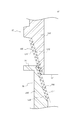
- FIG. 17 shows a state in which a conventional male screw member 10 ′ having a male screw portion 120 ′ made of a tapered male screw is screwed into a conventional female screw member 20 ′ having a female screw portion 220 ′ made of a tapered female screw.
- the male screw portion 120 ' has a configuration in a case where the entire screw portion 120 of FIG. More specifically, the threaded portion 120 'in FIG. 17 is such that the peak line L11' and the valley bottom line L12 'are parallel to each other, and are moved toward the inner peripheral side toward the tip 11' of the male screw member 10 '.
- the external thread 120 ′ is, for example, a tapered external thread specified in JIS B0203.
- the internal thread 220 ' is the same as the internal thread 220' of FIG. 2. More specifically, the peak line L21 'and the valley bottom line L22' are parallel to each other, and each has an internal thread member. It is inclined at a certain angle with respect to the axial direction of the female screw member 20 'so as to approach the outer peripheral side toward the opening end 21' of 20 '.
- the internal thread portion 220 ' is, for example, a tapered internal thread defined in JIS B0203.
- FIG. 18 shows a state in which a conventional male screw member 10 ′ having a male screw portion 120 ′ formed of a tapered male screw is screwed into a conventional female screw member 20 ′ having a female screw portion 220 ′ formed of a parallel female screw. , Is schematically shown.
- the configuration of the external thread portion 120 ' is the same as that in FIG.
- the internal thread portion 220 ' is the same as the internal thread portion 220' of FIG.
- the peak line L21 'and the valley bottom line L22' are parallel to each other, and the female thread member 20 ' Parallel to the axial direction. Accordingly, the root diameter and the inner diameter of the female screw portion 220 'become constant along the axial direction of the female screw portion 220'.
- the internal thread 220 ' is, for example, a parallel internal thread defined in JIS B0203.
- the outer diameter and the valley diameter on the tip 11 ′ side of the male screw part 120 ′ are respectively somewhat larger than the valley diameter and the inner diameter on the open end 21 ′ side of the female screw part 220 ′. It is set small.
- the oblique screwing is easily caused mainly when one of the male screw member 10 ′ and the female screw member 20 ′ is made of resin and the other is made of metal, because the difference in strength between the two becomes large.
- the resin thread of the male screw part 120 ′ and the female screw part 220 ′ is damaged, and the fluid tightness between the male screw part 120 ′ and the female screw part 220 ′ decreases. Or may be done.
- the peak line L11 of the male screw portion 120 is different from the respective peak line portions uL111 (uL11) with respect to the respective peak line portions uL111 (uL11).
- each valley bottom line portion uL121 is on an extension line euL122 from another valley bottom line portion uL122 (uL12) adjacent to the root side RE with respect to the valley bottom line portion uL121 (uL12). Or is located on the outer peripheral side of the extension line euL122.
- the peak line L11 of the external thread portion 120 has at least a portion where the peak line portion uL111 (uL11) is adjacent to the root side RE with respect to the peak line portion uL111 (uL11). ), And / or at least a part of the valley bottom line L12 (uL12) of the external thread portion 120 is formed on the outer peripheral side of the extension line euL112 from the valley bottom line portion uL121 (uL12). Is located on the outer peripheral side with respect to an extension line euL122 from another valley bottom line portion uL122 (uL12) adjacent to the root side RE. As a result, as in the examples of FIGS.
- the crest line L11 of the male thread portion 120 is such that each crest line portion uL111 (uL11) that is continuous from each bending point P11 (P111, P112) to the distal end 11 side TE is With respect to the peak line portion uL111 (uL11), it is located on the outer peripheral side with respect to an extension line euL112 from another peak line portion uL112 (uL11) adjacent to the root side RE.
- the valley bottom line L12 of the male thread portion 120 is such that the valley bottom line portion uL121 (uL12) continuous from the bending point P12 to the distal end 11 side TE is closer to the root than the valley bottom line portion uL121 (uL12).
- each peak line portion uL11 extends on an extension of each other, and each valley bottom line portion uL12 extends on the extension of each other).
- the outer diameter and the valley diameter of the male screw portion 120 are larger at the portion on the distal end 11 side than the bending points P11 and P12 as compared with the case where , And is displaced to the outer peripheral side.
- the gap between the external thread portion 120 and the internal thread portion 220 ' can be reduced shortly after the screwing is started, whereby the unevenness of the external thread member 10 with respect to the internal thread member 20' can be suppressed, Diagonal screwing can be suppressed. As a result, it is possible to reduce the possibility that the thread of the external thread 120 is damaged or the fluid tightness between the external thread 120 and the internal thread 220 ′ is reduced.
- the crest line L11 at the distal end side portion 122 of the male screw portion 120 is at least partially extended from the crest line L11 at the tapered portion 121.
- the valley bottom line L12 at the distal end portion 122 is located on the outer peripheral side with respect to the extension line eL12 from the valley bottom line L12 at the tapered portion 121 at least at a part thereof. I have. Accordingly, as compared with the case where the entire thread portion 120 is temporarily formed of the tapered portion 121 as in the examples of FIGS. 17 and 18, in the axial direction region corresponding to the distal end side portion 122, the external thread portion 120 is formed.
- the outer diameter and / or the valley diameter of the outer thread portion become large, and at least a part of the surface (the crest 120cr, the valley bottom 120ro, and the flank between the crest 120cr and the valley bottom 120ro) of the male screw portion 120 is displaced to the outer peripheral side.
- the peak line L11 at the distal end portion 122 is at least a part thereof (more specifically, a portion from the bending point P111 of the most root RE to the distal end 11 TE; the distal end portion).
- the entire peak line L11 at 122) is located on the outer peripheral side of the extension line eL11 from the peak line L11 at the tapered portion 121.
- the valley bottom line L12 at the tip side portion 122 is at least partially (more specifically, only the portion from the bending point P12 to the tip 11 side TE) than the extension line eL12 from the valley bottom line L12 at the tapered portion 121.
- the gap between the external thread portion 120 and the internal thread portion 220 ' can be reduced shortly after the screwing is started, whereby the unevenness of the external thread member 10 with respect to the internal thread member 20' can be suppressed, Diagonal screwing can be suppressed. As a result, it is possible to reduce the possibility that the thread of the external thread 120 is damaged or the fluid tightness between the external thread 120 and the internal thread 220 ′ is reduced.
- the angle of the valley bottom line L12 at the tip side portion 122 on the acute angle side with respect to the axial direction is at least partly greater than the angle of the valley bottom line L12 at the taper portion 121 on the acute angle side with respect to the axial direction. small. More specifically, of the valley bottom line L12 at the distal end side portion 122, the angle ⁇ 122 of the acute angle side with respect to the axial direction in the portion on the distal end 11 side from the bending point P12 is the axis of the valley bottom line L12 at the tapered portion 121. It is smaller than the angle ⁇ 121 on the acute angle side with respect to the direction ( ⁇ 122 ⁇ 121).
- the angle of the valley bottom line L12 at the distal end portion 122 on the acute angle side with respect to the axial direction becomes smaller toward the distal end 11 side TE.
- the root diameter of the external thread portion 120 increases in the axial direction region corresponding to the distal end side portion 122 as compared with the case where the entire thread portion 120 is temporarily formed by the tapered portion 121. Consequently, the portion of the surface of the male screw portion 120 on the valley bottom 120ro side is displaced to the outer peripheral side. Therefore, the gap between the external thread portion 120 and the internal thread portion 220 'can be reduced shortly after the screwing is started, whereby the unevenness of the external thread member 10 with respect to the internal thread member 20' can be suppressed, Diagonal screwing can be suppressed.
- the angle on the acute side with respect to the axial direction of the peak line L11 at the distal end side portion 122 is at least partially greater than the angle on the acute side with respect to the axial direction of the peak line L11 at the tapered portion 121. small. More specifically, of the peak line L11 at the distal end portion 122, the angle ⁇ 112 ( ⁇ 1121, ⁇ 1122) on the acute angle side with respect to the axial direction in the portion on the distal end 11 side of the bending point P11 (P111) on the most proximal side RE with respect to the axial direction.
- the angle ⁇ 1122 of the acute angle side with respect to the axial direction in the portion of the tip 11 side TE from the bending point P11 (P112) of the tip 11 side TE of the peak line L11 at the tip side 122 is smaller ( ⁇ 1122 ⁇ 1121).
- the angle of the peak line L11 at the distal end portion 122 on the acute angle side with respect to the axial direction becomes smaller toward the distal end 11 side TE.
- the outer diameter of the external thread portion 120 increases in the axial direction region corresponding to the distal end side portion 122 as compared with the case where the entire thread portion 120 is temporarily formed by the tapered portion 121. Consequently, a portion of the surface of the male thread portion 120 on the side of the peak 120cr is displaced to the outer peripheral side. Therefore, the gap between the external thread portion 120 and the internal thread portion 220 'can be reduced shortly after the screwing is started, whereby the unevenness of the external thread member 10 with respect to the internal thread member 20' can be suppressed, Diagonal screwing can be suppressed.
- the peak height of the thread 120ri located on the boundary surface B10 between the tapered portion 121 and the distal end portion 122 is counted as the peak height h121 of the tapered portion 121 instead of the distal end portion 122.
- the “peak height (h121, h122)” of the thread 120ri of the male screw portion 120 is a distance from the valley bottom line L12 to the ridge 120cr when measured perpendicularly to the valley bottom line L12. I do.
- the “crest height (h121, h122)” is the valley bottom. It is assumed that this is the maximum value of the distance from the valley bottom line L12 to the peak 20cr when measured perpendicularly to the line L12.
- the male screw member 10 according to the first embodiment is not limited to the one shown in FIG. 2, and various modifications are possible.
- the valley bottom line L12 may have two or more bending points P12.
- the angle of the valley bottom line L12 at the tip side portion 122 on the acute angle side with respect to the axial direction is made smaller toward the tip end 11 side TE.
- the bending point P12 of the root side RE of the valley bottom line L12 may be located closer to the root side RE than the bending point P11 of the root side RE of the peak line L11.
- the boundary surface B10 between the tapered portion 121 and the tip side portion 122 passes through the bending point P12 on the root side RE of the valley bottom line L12.
- the peak line L11 of the male screw part 120 has at least one bend similarly to the first embodiment. It has a point P11 and / or the valley bottom line L12 of the external thread 120 has at least one bending point P12.
- the peak line L11 of the male screw portion 120 is such that each peak line portion uL111 (uL11) is adjacent to the root side RE with respect to the peak line portion uL111 (uL11).
- the valley bottom line L12 of the male screw portion 120 is each valley bottom line portion uL121 (uL12). Respectively extend on the extension line euL122 from the other valley bottom line portion uL122 (uL12) adjacent to the root RE with respect to the valley bottom line portion uL121 (uL12), or extend from the extension line euL122. It is located on the outer peripheral side.
- the peak line L11 of the external thread portion 120 has at least a portion where the peak line portion uL111 (uL11) is adjacent to the root side RE with respect to the peak line portion uL111 (uL11).
- the valley bottom line L12 (uL12) of the external thread portion 120 is formed on the outer peripheral side of the extension line euL112 from the valley bottom line portion uL121 (uL12). Is located on the outer peripheral side with respect to an extension line euL122 from another valley bottom line portion uL122 (uL12) adjacent to the root side RE. More specifically, the crest line L11 of the male screw portion 120 is such that each crest line portion uL111 (uL11) that is continuous from each bending point P11 to the tip end 11 side TE corresponds to the crest line portion uL111 (uL11).
- the outermost line euL112 from the other crest line portion uL112 (uL11) adjacent to the root side RE is located on the outer peripheral side, and / or the valley bottom line L12 of the male thread portion 120 is located on the tip 11 side from each bending point P12.
- the valley bottom line portion uL121 (uL12) connected to the TE is located on the outer peripheral side of the extension line euL122 from the other valley bottom line portion uL122 (uL12) adjacent to the root RE with respect to the valley bottom line portion uL121 (uL12). positioned.
- the male screw member 10 In the male screw member 10 (FIGS.
- the male screw portion 120 has a tapered portion 121 and a tip side portion 122, and the tapered portion 121 B10 between the tip end side portion 122 and the bending point P11 of the peak line L11 and the bending point P12 of the valley bottom line L12 pass through the bending point closest to the root RE and are virtual surfaces perpendicular to the axial direction. It is something that is.
- at least a part of the peak line L11 at the distal end portion 122 is located on the outer peripheral side with respect to the extension line eL11 from the peak line L11 at the tapered portion 121, and / or a valley at the distal end portion 122.
- the line L12 is at least partially located on the outer peripheral side with respect to the extension line eL12 from the bottom line L12 at the tapered portion 121.
- the configuration of the female screw member 20 ′ suitable for use with the male screw member 10 (FIGS. 4 to 9) according to the second to seventh embodiments is the same as that described in the first embodiment. The same is true.
- FIG. 4 is a drawing corresponding to FIG. 2, and a part of each of the male screw member 10 of the second embodiment and a female screw member 20 ′ similar to the female screw member 20 ′ of FIG. 2 is enlarged. Is shown.
- the screw member 10 of the second embodiment differs from the first embodiment only in the configuration of the valley bottom line L12 and the peak line L11 at the distal end side portion 122 of the male screw portion 120.
- Other configurations are the same as those of the first embodiment.
- a configuration when a cross section including the axis O of the male screw member 10 is viewed will be described.
- the peak line L11 of the male screw portion 120 has two bending points P11 (a bending point P111 and a bending point P112 located on the side of the distal end 11 TE therefrom).
- the valley bottom line L12 of the portion 120 has one bending point P12.
- the bending point P111 of the most root side RE of the peak line L11 is located on the root side RE from the bending point P12 of the valley bottom line L12. Pass through the bending point P111 of the most root side RE.
- the valley bottom line L12 of the male thread portion 120 is such that a valley bottom line portion uL121 (uL12) that is continuous from the bending point P12 to the distal end 11 side TE is closer to the root RE than the valley bottom line portion uL121 (uL12). It is located on the outer peripheral side with respect to an extension line euL122 from another adjacent valley bottom line portion uL122 (uL12).
- the valley bottom line L12 at the tip side portion 122 is at least partially (more specifically, only the portion from the bending point P12 to the tip 11 side TE) than the extension line eL12 from the valley bottom line L12 at the tapered portion 121.
- the angle of the valley bottom line L12 at the tip side portion 122 on the acute angle side with respect to the axial direction is at least partially smaller than the angle of the valley bottom line L12 at the tapered portion 121 on the acute angle side with respect to the axial direction. More specifically, of the valley bottom line L12 at the tip side portion 122, the angle ⁇ 122 of the acute angle side with respect to the axial direction at the portion of the tip 11 side TE from the bending point P12 is the axial direction of the valley bottom line L12 at the tapered portion 121. Is smaller than the acute angle ⁇ 121 with respect to ( ⁇ 122 ⁇ 121).
- the angle of the valley bottom line L12 at the distal end portion 122 on the acute angle side with respect to the axial direction becomes smaller toward the distal end 11 side TE.
- the angle of the valley bottom line L12 at the tip side portion 122 on the acute angle side with respect to the axial direction is greater than 0 ° as a whole. More specifically, of the valley bottom line L12 at the distal end side portion 122, a portion closer to the distal end 11 side than the bending point P12 extends toward the inner peripheral side IR toward the distal end 11 side TE.
- the angle ⁇ 122 on the acute angle side with respect to the axial direction in this portion is larger than 0 ° ( ⁇ 122> 0 °).
- the peak line L11 of the male thread portion 120 is such that each peak line portion uL111 (uL11) that is continuous from each bending point P11 (P111, P112) to the distal end 11 side TE is the peak line.
- the portion uL111 (uL11) is located on the outer peripheral side with respect to the extension line euL112 extending from another peak line portion uL112 (uL11) adjacent to the root RE.
- the peak line L11 at the distal end portion 122 is at least a part thereof (more specifically, a portion from the bending point P111 of the most root side RE to the distal end 11 side; the entire peak line L11 at the distal end portion 122).
- the outer peripheral side of the extension line eL11 from the peak line L11 at the tapered portion 121 is located.
- the angle on the acute angle side of the peak line L11 at the distal end portion 122 with respect to the axial direction is at least partially smaller than the angle of the taper portion 121 on the acute angle side with respect to the axial direction. More specifically, of the peak line L11 at the distal end portion 122, the angle ⁇ 112 ( ⁇ 1121, ⁇ 1122) on the acute angle side with respect to the axial direction in the portion on the distal end 11 side of the bending point P11 (P111) on the most proximal side RE with respect to the axial direction.
- the acute angle ⁇ 1122 with respect to the axial direction in the portion on the distal end 11 side from the bending point P11 (P112) closest to the distal end 11 is the peak at the distal end portion 122.
- the angle between the two bending points P11 (P111, P112) of the line L11 on the acute angle side with respect to the axial direction at the portion between the two bending points P11 (P111, P112) is smaller than the angle ⁇ 1121 ( ⁇ 1122 ⁇ 1121).
- the angle of the peak line L11 at the distal end portion 122 on the acute angle side with respect to the axial direction becomes smaller toward the distal end 11 side TE.
- the angle on the acute angle side with respect to the axial direction of the peak line L11 at the tip side portion 122 is greater than 0 ° as a whole. More specifically, of the peak line L11 at the distal end portion 122, a portion closer to the distal end 11 TE than the bending point P11 (P112) of the distal most 11 side TE is shifted toward the distal end 11 TE toward the inner peripheral side IR.
- the angle ⁇ 112 ( ⁇ 1122) on the acute angle side with respect to the axial direction in the portion is larger than 0 ° ( ⁇ 1122> 0 °). Even with such a configuration, although there may be a difference in the degree, as in the first embodiment shown in FIG. In the axial region corresponding to the portion 122, the outer diameter of the male screw portion 120 increases, and the portion of the surface of the male screw portion 120 on the peak 120 cr side is displaced to the outer peripheral side.
- the male screw member 10 according to the second embodiment is not limited to the one shown in FIG. 4, and various modifications are possible.
- the valley bottom line L12 may have two or more bending points P12.
- the angle of the valley bottom line L12 at the tip side portion 122 on the acute angle side with respect to the axial direction is made smaller toward the tip end 11 side TE.
- a portion closer to the distal end 11 side than the bending point P12 of the distal end 11 side TE is directed toward the inner peripheral side IR toward the distal end 11 side TE.
- the angle ⁇ 122 on the acute angle side with respect to the axial direction in the portion is set to be larger than 0 ° ( ⁇ 122> 0 °).
- the peak line L11 may have only one bending point P11 or three or more bending points P11.
- the angle on the acute side with respect to the axial direction of the peak line L11 at the distal end side portion 122 is set to be smaller toward the distal end 11 side TE.
- a portion closer to the distal end 11 side than the bending point P11 of the distal end 11 side TE is directed toward the inner peripheral side IR toward the distal end 11 side TE.
- the angle ⁇ 112 of the portion on the acute angle side with respect to the axial direction is larger than 0 ° ( ⁇ 112> 0 °).
- the bending point P12 of the root side RE of the valley bottom line L12 may be located closer to the root side RE than the bending point P11 of the root side RE of the peak line L11.
- the boundary surface B10 between the tapered portion 121 and the tip side portion 122 passes through the bending point P12 on the root side RE of the valley bottom line L12.
- FIG. 5 is a drawing corresponding to FIG. 2, in which a part of each of the male screw member 10 of the third embodiment and a female screw member 20 ′ similar to the female screw member 20 ′ of FIG. 2 is enlarged. Is shown.
- the screw member 10 of the third embodiment differs from the first embodiment only in the configuration of the valley bottom line L12 and the peak line L11 at the distal end side portion 122 of the male screw portion 120.
- Other configurations are the same as those of the first embodiment.
- a configuration when a cross section including the axis O of the male screw member 10 is viewed will be described.
- the peak line L11 of the male screw portion 120 has two bending points P11 (a bending point P111 and a bending point P112 located on the distal end 11 side TE side from the bending point P111).
- the valley bottom line L12 of the portion 120 has one bending point P12.
- the bending point P111 of the most root side RE of the peak line L11 is located on the root side RE from the bending point P12 of the valley bottom line L12. Pass through the bending point P111 of the most root side RE.
- the valley bottom line L12 of the male thread portion 120 is such that the valley bottom line portion uL121 (uL12) that is continuous from the bending point P12 to the tip end 11 side TE is on the root side RE with respect to the valley bottom line portion uL121 (uL12). It is located on the outer peripheral side with respect to an extension line euL122 from another adjacent valley bottom line portion uL122 (uL12).
- the valley bottom line L12 at the tip side portion 122 is at least partially (more specifically, only the portion from the bending point P12 to the tip 11 side TE) than the extension line eL12 from the valley bottom line L12 at the tapered portion 121. Are also located on the outer peripheral side.
- the valley bottom line L12 at the distal end side portion 122 extends at least partially toward the outer peripheral side OR toward the distal end 11 side TE. More specifically, the valley bottom line L12 in the distal end portion 122 extends only toward the distal end 11 TE from the inflection point P12 and extends toward the outer peripheral side toward the distal end 11 TE. Even with such a configuration, although there may be a difference in the degree, as in the first embodiment shown in FIG. In the axial region corresponding to the portion 122, the root diameter of the external thread portion 120 becomes large, and the portion of the surface of the external thread portion 120 on the side of the root 120ro is displaced to the outer peripheral side. In the example of FIG.
- the angle ⁇ 122 on the acute angle side with respect to the direction is preferably equal to or less than the angle ⁇ 121 on the acute angle side with respect to the axial direction of the bottom line L12 of the tapered portion 121 ( ⁇ 122 ⁇ ⁇ 121).
- the peak line L11 of the male thread portion 120 is such that each peak line portion uL111 (uL11) continuous from each bending point P11 (P111, P112) to the distal end 11 side TE is the peak line.
- the portion uL111 (uL11) is located on the outer peripheral side with respect to the extension line euL112 extending from another peak line portion uL112 (uL11) adjacent to the root RE.
- the peak line L11 at the distal end portion 122 is at least a part thereof (more specifically, a portion from the bending point P111 of the most root side RE to the distal end 11 side; the entire peak line L11 at the distal end portion 122).
- the outer peripheral side of the extension line eL11 from the peak line L11 at the tapered portion 121 is located.
- the peak line L11 at the distal end portion 122 extends at least partially toward the outer peripheral side OR toward the distal end 11 side TE. More specifically, the peak line L11 at the distal end side portion 122 is only the portion from the bending point P11 (P112) of the distal end 11 side TE to the distal end 11 side TE. So that it extends. Even with such a configuration, although there may be a difference in the degree, as in the first embodiment shown in FIG.
- the outer diameter of the male screw portion 120 increases, and the portion of the surface of the male screw portion 120 on the peak 120 cr side is displaced to the outer peripheral side.
- the portion between the two bending points P11 (P111, P112) of the peak line L11 at the distal end side portion 122 is more toward the inner peripheral side IR toward the distal end 11 side TE. So that it extends.
- this portion may extend toward the outer peripheral side OR toward the distal end 11 side TE, or may extend parallel to the axial direction.
- P11 P111, P112
- the bending point P11 (P111) of the most root side RE is higher than the bending point P11 (P111). It is preferable that the angle ⁇ 112 ( ⁇ 1121, ⁇ 1122) of the acute angle side with respect to the axial direction in the portion of the tip 11 side TE be equal to or smaller than the acute angle ⁇ 111 ( ⁇ 112 ⁇ ⁇ 111) with respect to the axial direction of the peak line L11 in the tapered portion 121. It is.
- the male screw member 10 according to the third embodiment is not limited to the one shown in FIG. 5, and various modifications are possible.
- the valley bottom line L12 may have two or more bending points P12.
- the valley bottom line L12 at the distal end side portion 122 extends at least in the portion closer to the distal end 11 TE than the bending point P12 of the distal end 11 TE so as to be more outward toward the distal end 11 TE.
- the peak line L11 may have only one bending point P11 or three or more bending points P11.
- the peak line L11 at the distal end side portion 122 extends at least from the bending point P11 of the distal end 11 side TE toward the distal end 11 TE toward the outer peripheral side OR toward the distal end 11 TE.
- the bending point P12 of the root side RE closest to the valley bottom line L12 may be located closer to the root side RE than the bending point P11 of the root side RE of the peak line L11.
- the boundary surface B10 between the tapered portion 121 and the tip side portion 122 passes through the bending point P12 on the root side RE of the valley bottom line L12.
- FIG. 6 is a view corresponding to FIG. 2, in which a part of each of the external thread member 10 of the fourth embodiment and an internal thread member 20 ′ similar to the internal thread member 20 ′ of FIG. 2 is enlarged. Is shown.
- the screw member 10 of the fourth embodiment is different from the first embodiment only in the configuration of the peak line L11 at the distal end portion 122 of the male screw portion 120.
- Other configurations are the same as those in the first embodiment.
- a configuration when a cross section including the axis O of the male screw member 10 is viewed will be described.
- the peak line L11 of the male screw portion 120 does not have a bending point and extends in a straight line, and the bottom line L12 of the male screw portion 120 has one bending point. P12 is provided.
- a boundary surface B10 between the tapered portion 121 and the tip side portion 122 passes through a bending point P12 of the valley bottom line L12.
- the screw thread 120ri in the tip side part 122 is roughly formed by cutting out a part of the screw tip 120ri in the tip side part 122 in the example of FIG.
- the crest 120cr of the screw thread 120ri in the tip side portion 122 extends linearly along the crest line L11, and is inclined at an angle ⁇ 112 with respect to the axial direction.
- the thread height h122 of the thread 120ri in at least a part (all in the example of FIG. 6) of the distal end side portion 122 is smaller than the thread height h121 of the thread 120ri in the tapered portion 121 (h122). ⁇ H121).
- the height h122 of the thread 120ri of the distal end portion 122 gradually decreases toward the distal end 11 side TE.
- the outer diameter of the external thread portion 120 is equal in the axial direction region corresponding to the distal end side portion 122 as compared with the case where the entire thread portion 120 is temporarily formed by the tapered portion 121. Accordingly, the position of the peak 120cr on the surface of the male screw portion 120 is maintained.
- the external thread portion 120 is compared with the case where the entire thread portion 120 is temporarily formed by the tapered portion 121.
- the outer diameter becomes equal and the valley diameter becomes larger.
- the position of the crest 120cr on the surface of the male screw portion 120 is maintained, and the portion on the valley bottom 120ro side is displaced to the outer peripheral side.
- the interference between the external thread portion 120 and the internal thread portion 220 ′ shortly after the start of screwing can be reduced, and the gap between them can be made more appropriate as compared with the first embodiment.
- the male screw member 10 according to the fourth embodiment is not limited to the one shown in FIG. 6, and various modifications are possible.
- the valley bottom line L12 may have two or more bending points P12.
- the angle of the valley bottom line L12 at the tip side portion 122 on the acute angle side with respect to the axial direction is made smaller toward the tip end 11 side TE.
- the same effect as the example of FIG. 6 described above can be obtained.
- FIG. 7 is a drawing corresponding to FIG. 2, and a part of each of the male screw member 10 of the fifth embodiment and a female screw member 20 ′ similar to the female screw member 20 ′ of FIG. 2 is enlarged. Is shown.
- the threaded member 10 of the fifth embodiment is different from the fourth embodiment only in the configuration of the valley bottom line L12 at the distal end side portion 122 of the male thread portion 120.
- the peak line L11 of the male screw portion 120 does not have a bending point and extends in a straight line, and the root line L12 of the male screw portion 120 has one bending point.
- P12 is provided.
- a boundary surface B10 between the tapered portion 121 and the tip side portion 122 passes through a bending point P12 of the valley bottom line L12.
- the valley bottom line L12 of the male thread portion 120 is such that a valley bottom line portion uL121 (uL12) that is continuous from the bending point P12 to the distal end 11 side TE is closer to the root RE than the valley bottom line portion uL121 (uL12). It is located on the outer peripheral side with respect to an extension line euL122 from an adjacent other valley bottom line portion uL122 (uL12).
- the valley bottom line L12 at the distal end side portion 122 is at least partly (more specifically, a portion from the bending point P12 to the distal end 11 side TE. All of the valley bottom line L12 at the distal end side portion 122).
- the angle of the valley bottom line L12 at the tip side portion 122 on the acute angle side with respect to the axial direction is at least partially smaller than the angle of the valley bottom line L12 at the tapered portion 121 on the acute angle side with respect to the axial direction. More specifically, of the valley bottom line L12 at the tip side portion 122, the angle ⁇ 122 of the acute angle side with respect to the axial direction at the portion of the tip 11 side TE from the bending point P12 is the axial direction of the valley bottom line L12 at the tapered portion 121. Is smaller than the acute angle ⁇ 121 with respect to ( ⁇ 122 ⁇ 121).
- the angle of the valley bottom line L12 at the distal end portion 122 on the acute angle side with respect to the axial direction becomes smaller toward the distal end 11 side TE.
- the angle of the valley bottom line L12 at the tip side portion 122 on the acute angle side with respect to the axial direction is greater than 0 ° as a whole. More specifically, of the valley bottom line L12 at the distal end side portion 122, a portion closer to the distal end 11 side than the bending point P12 extends toward the inner peripheral side IR toward the distal end 11 side TE.
- the angle ⁇ 122 on the acute angle side with respect to the axial direction in this portion is larger than 0 ° ( ⁇ 122> 0 °).
- the male screw member 10 according to the fifth embodiment is not limited to the one shown in FIG. 7, and various modifications are possible.
- the valley bottom line L12 may have two or more bending points P12.
- the angle of the valley bottom line L12 at the tip side portion 122 on the acute angle side with respect to the axial direction is made smaller toward the tip end 11 side TE.
- a portion closer to the distal end 11 side than the bending point P12 of the distal end 11 side TE is directed toward the inner peripheral side IR toward the distal end 11 side TE.
- the angle ⁇ 122 on the acute angle side with respect to the axial direction in the portion is set to be larger than 0 ° ( ⁇ 122> 0 °). Also in these configurations, the same effects as in the example of FIG. 7 described above can be obtained.
- FIG. 8 is a view corresponding to FIG. 2, in which a part of each of the male screw member 10 of the sixth embodiment and a female screw member 20 ′ similar to the female screw member 20 ′ of FIG. 2 is enlarged. Is shown.
- the male screw member 10 of the sixth embodiment is different from the first embodiment only in the configuration of the top line L11 and the bottom line L12 of the distal end portion 122 of the external thread portion 120.
- Other configurations are the same as those of the first embodiment.
- a configuration when a cross section including the axis O of the male screw member 10 is viewed will be described.
- the peak line L11 of the male screw portion 120 has one bending point P11, and the bottom line L12 of the male screw portion 120 has no bending point, and is straight. Extends. A boundary surface B10 between the tapered portion 121 and the tip side portion 122 passes through a bending point P11 of the peak line L11.
- each valley bottom line portion uL12 extends on an extension of each other.
- the thread height h122 of the thread 120ri in at least a part (all in the example of FIG.
- the root diameter of the male screw portion 120 is equal to that in the case where the entire screw portion 120 is constituted by the tapered portion 121. Accordingly, the position of the portion on the valley bottom 120ro side of the surface of the male screw portion 120 is maintained.
- the peak line L11 of the male thread portion 120 is such that each peak line portion uL111 (uL11) that is continuous from the bending point P11 to the distal end 11 side TE has a root side RE with respect to the peak line portion uL111 (uL11). Is located on the outer peripheral side with respect to the extension line euL112 from the other peak line portion uL112 (uL11) adjacent to.
- the peak line L11 at the distal end portion 122 is at least partially (more specifically, a portion from the bending point P11 to the distal end 11 side TE; the entire peak line L11 at the distal end portion 122) is a tapered portion.
- the angle on the acute angle side of the peak line L11 at the distal end portion 122 with respect to the axial direction is at least partially smaller than the angle of the taper portion 121 on the acute angle side with respect to the axial direction. More specifically, of the peak line L11 at the tip side portion 122, the angle ⁇ 112 of the acute angle side with respect to the axial direction at the portion of the tip 11 side TE with respect to the bending point P11 is the axial direction of the peak line L11 at the tapered portion 121. Is smaller than the acute angle ⁇ 111 ( ⁇ 112 ⁇ 111).
- the angle of the peak line L11 at the distal end portion 122 on the acute angle side with respect to the axial direction becomes smaller toward the distal end 11 side TE.
- the outer diameter of the external thread portion 120 increases in the axial direction region corresponding to the distal end side portion 122 as compared with the case where the entire thread portion 120 is temporarily formed by the tapered portion 121. Consequently, a portion of the surface of the male thread portion 120 on the side of the peak 120cr is displaced to the outer peripheral side.
- the height h122 of the thread 120ri in at least a part (all in the example of FIG. 8) of the distal end side portion 122 is the height of the thread 120ri in the taper portion 121. Since h ⁇ b> 121 is larger than h ⁇ b> 121 (h ⁇ b>122> h ⁇ b> 121), at least a part (all in the example of FIG. 8) of the distal end side part 122 is compared with a case where the entire thread part 120 is temporarily formed by the tapered part 121. The volume of the screw thread 120ri increases.
- the thread height h122 of the thread 120ri at the distal end portion 122 is equal to or less than the thread height h122 of the thread 120ri at the tapered portion 121. Since (h122 ⁇ h121) is suppressed, the compressive breakage of the external thread member 10 at the time of screwing can be prevented.
- the male screw member 10 according to the sixth embodiment is not limited to the one shown in FIG. 8, and various modifications are possible.
- the peak line L11 may have two or more bending points P11.
- the angle on the acute side with respect to the axial direction of the peak line L11 at the distal end side portion 122 is set to be smaller toward the distal end 11 side TE.
- the same effect as the example of FIG. 8 described above can be obtained.
- FIG. 9 is a view corresponding to FIG. 2, in which a part of each of the male screw member 10 of the seventh embodiment and a female screw member 20 ′ similar to the female screw member 20 ′ of FIG. 2 is enlarged. Is shown.
- the male screw portion 120 does not have the tapered portion 121, and further does not have the distal end side portion 122 continuing from the tapered portion 121.
- a configuration when a cross section including the axis O of the male screw member 10 is viewed will be described.
- the peak line L11 of the male screw portion 120 has a plurality of bending points P11, and the plurality of bending points P11 extend from the root side RE of the peak line L11 to the tip end TE. It exists almost entirely.
- the valley bottom line L12 of the external thread portion 120 has a plurality of bending points P12, and the plurality of bending points P12 extend from the root side RE of the valley bottom line L12 to the tip end 11 side TE over substantially the entirety. Existing.
- the valley bottom line L12 of the external thread portion 120 is such that a valley bottom line portion uL121 (uL12) that is continuous from each bending point P12 to the tip end 11 side TE is at the root of the valley bottom line portion uL121 (uL12). It is located on the outer peripheral side with respect to an extension line euL122 from another valley bottom line portion uL122 (uL12) adjacent to the side RE.
- the angle ⁇ 12 of each valley bottom line portion uL12 on the acute angle side with respect to the axial direction gradually decreases toward the front end 11 side TE.
- the valley bottom line portions uL12 one or more (two in the example of FIG.
- valley bottom line portions uL12 located at the most distal end TE side have an acute angle side angle ⁇ 12 with respect to the axial direction of 0 °. is there. Even with such a configuration, although there may be a difference in the degree, as in the first embodiment shown in FIG. On the side TE, the root diameter of the external thread portion 120 increases, and the portion of the surface of the external thread portion 120 on the side of the root bottom 120ro is displaced outward.
- the crest line L11 of the male thread portion 120 is such that each crest line portion uL111 (uL11) that is continuous from each bending point P11 to the end 11 side TE is the crest line portion uL111 (uL11). Is located on the outer peripheral side with respect to an extension line euL112 from another peak line portion uL112 (uL11) adjacent to the root RE. The angle ⁇ 11 of each peak line portion uL11 on the acute angle side with respect to the axial direction gradually decreases toward the front end 11 side TE.
- One or a plurality one in the example of FIG.
- the male screw portion 120 has the same crest height h120 of each screw thread 120ri.
- the male screw member 10 according to the seventh embodiment is not limited to the one shown in FIG. 9, and various modifications are possible.
- the angle ⁇ 12 of the valley bottom line L12 on the acute angle side with respect to the axial direction of the valley bottom line portion uL12 located on the front end 11 side TE may be larger than 0 ° ( ⁇ 12> 0 °).
- the angle ⁇ 11 of the peak line L11 on the acute angle side with respect to the axial direction of the peak line portion uL11 located on the most distal end 11 side TE may be larger than 0 ° ( ⁇ 11> 0 °).
- FIG. 9 the angle ⁇ 12 of the valley bottom line L12 on the acute angle side with respect to the axial direction of the valley bottom line portion uL12 located on the front end 11 side TE may be larger than 0 ° ( ⁇ 12> 0 °).
- the crest height h120 of the screw thread 120ri of the male screw part 120 may be gradually reduced toward at least the tip 11 side TE at least at the tip 11 side TE. It may be gradually increased toward the eleventh TE. Further, in the example of FIG. 9, the thread 120ri of the male screw portion 120 may have a substantially trapezoidal shape at least at the portion on the side of the distal end 11 as in the examples of FIGS. 6 and 7. In these configurations, the same effects as in the example of FIG. 2 described above can be obtained.
- the screw member 10 is formed in a tubular shape as shown in the example of the drawing, and the tapered portion 121 is formed of a tapered male screw specified in JIS B0203.
- the entire distal end portion 122 (and thus the boundary surface B10 between the tapered portion 121 and the distal end portion 122) is closer to the distal end 11 of the male screw member 10 than the reference diameter position (reference surface) GP. It is preferable to be located at TE.
- the “reference diameter position (reference surface) (GP)” is a position of the reference diameter of the male screw, which is defined corresponding to the nominal diameter (nominal of the screw) of the tapered male screw constituting the tapered portion 121.
- the reference diameter position (reference surface) GP of the male screw member 10 is an axial position away from the tip end 11 by a reference length a (FIG. 2).
- the “reference length (a)” is a reference length defined in JIS B0203 with respect to a nominal diameter (nominal diameter of a thread) of a tapered male screw constituting the tapered portion 121. If the entire threaded portion 120 is formed of the tapered portion 121, at the time of screwing, the portion between the reference diameter position (reference surface) GP and the tip 11 side TE and the female threaded portion 220 ′.
- a gap is easily formed, and as a result, oblique screwing is likely to occur, and fluid tightness between the male screw member and the female screw member after screwing tends to decrease. Therefore, according to the above configuration, the gap between the external thread portion 120 and the internal thread portion 220 'can be more reliably reduced shortly after the start of the screwing, whereby the oblique screwing can be more effectively performed. Can be suppressed. Further, the fluid tightness between the externally threaded member and the internally threaded member after screwing can be more effectively improved.
- the screw member 10 is formed in a tubular shape as shown in the example of the figure, and the tapered portion 121 is formed in a tapered male screw specified in JIS B0203.
- the entirety of the distal end portion 122 (and thus the boundary surface B10 between the tapered portion 121 and the distal end portion 122) is larger than the position of the reference diameter (reference surface) GP by the screw of the tapered portion 121. It is preferable to be located on the distal end 11 side TE of the male screw member 10 than the axial position located on the distal end 11 side TE for one pitch of the mountain 120ri.
- the “pitch” of the thread (120 ri) is specified in JIS B0203.
- the entire threaded portion 120 is formed of the tapered portion 121, when the threaded portion is further threaded by one pitch from the reference diameter position (reference surface) GP at the time of screwing, a gap between the male threaded member and the female threaded member is obtained. Fluid tightness is maintained. Therefore, with the above configuration, the oblique screwing can be more effectively suppressed, and the fluid tightness between the male screw member and the female screw member after screwing can be more effectively improved.
- the thread 120ri located on the boundary surface B10 between the tapered part 121 and the tip side part 122 is not included in the number of the threads 120ri of the tip side part 122.
- two threads 120 ri are arranged in the tip side 122 in the axial direction.
- the screw member 10 is formed in a tubular shape as shown in the example of the drawing, and the tapered portion 121 is formed of a tapered male screw specified in JIS B0203.
- the nominal diameter (nominal diameter of the thread) of the tapered male screw forming the tapered portion 121 is equal to or less than R1
- the above-described effects can be remarkably exhibited, so that it is good.
- “screw name” is specified in JIS B0203.
- FIG. 10 shows, in addition to the female screw member 20 of the present embodiment, a male screw member 10 ′ suitable for use with the female screw member 20 of the present embodiment for reference.
- the female screw member 20 according to the first embodiment shown in FIG. 10 is made of a resin material, and has a main body 210 and a screw 220 provided on the inner peripheral surface of the main body 210. Since the female screw member 20 of the present embodiment is made of a resin material, the weight can be reduced. However, the female screw member 20 may be made of a metal material.
- the female screw member 20 of the present embodiment is formed in a tubular shape, for example, as a pipe joint configured to be connected to another tubular member. As shown in FIG. 10, in a cross section including the axis O of the female screw member 20, the female screw part 220 includes a tapered part 221, an open end side part 222 continuous from the tapered part 221 to the open end 21 side OE, have.
- the tapered portion 221 is such that the top line L21 and the bottom line L22 of the female screw portion 220 are parallel to each other, and the female screw member is directed toward the outer peripheral side OR toward the open end 21 side OE of the female screw member 20. It is inclined at a constant angle ( ⁇ 211 and ⁇ 221) with respect to the axis direction of 20. Accordingly, the inner diameter and the valley diameter of the tapered portion 221 gradually increase toward the opening end 21 side OE. It is preferable that the tapered portion 221 has a configuration of a female tapered thread specified in JIS B 0203.
- the tapered portion 221 has a configuration in the axial direction region corresponding to the tapered portion 221 of the female screw portion 220 when the entire female screw portion 220 is a tapered female screw specified in JIS B0203. It is suitable to have.
- the peak line L21 of the female screw portion 220 has at least one bending point P21, and / or the root line L22 of the female screw portion 220 has at least one bending point P22.
- the peak line L21 of the female screw portion 220 has two bending points P21 (a bending point P211 and a bending point P212 located closer to the opening end 21 OE than this).
- the root line L22 of the female thread portion 220 has one bending point P22.
- a boundary surface B20 between the tapered portion 221 and the opening end side portion 222 passes through a bending point located on the innermost side BE of the bending point P21 of the peak line L21 and the bending point P22 of the valley bottom line L22, and extends in the axial direction. It is assumed to be a vertical virtual plane. In the example of FIG. 10, the bending point P211 on the deepest side BE of the peak line L21 is located on the deeper side BE than the bending point P22 on the valley bottom line L22, and the boundary between the tapered portion 221 and the open end side portion 222.
- the surface B20 passes through a bending point P211 on the innermost side BE of the peak line L21.
- the tapered portion 221 of the female screw portion 220 is a portion of the female screw portion 220 on the back side BE from the boundary surface B20.
- the open end side part 222 of the female screw part 220 is a part of the female screw part 220 from the boundary surface B20 to the open end 21 of the female screw member 20.
- the opening end side part 222 has a different configuration from the tapered part 221.
- the peak line L21 of the female screw portion 220 is formed such that each peak line portion uL211 (uL21) is another peak line adjacent to the back side BE with respect to the peak line portion uL211 (uL21).
- the root line L22 extending on the extension line euL212 from the portion uL212 (uL21) or located on the inner peripheral side with respect to the extension line euL212, and the root line L22 of the female thread portion 220 is the respective root line.
- the portion uL221 (uL22) extends on the extension line euL222 from another valley bottom line portion uL222 (uL22) adjacent to the back side BE with respect to the valley bottom line portion uL221 (uL22), respectively. It is located on the inner peripheral side of the extension line euL222.
- at least a part of the peak line L21 of the female screw portion 220 has a peak line portion uL211 (uL21) adjacent to the back side BE with respect to the peak line portion uL211 (uL21).
- the valley bottom line L22 (uL22) is located on the inner peripheral side with respect to the extension line euL212 from the peak line portion uL212 (uL21), and / or the valley bottom line portion uL221 (uL22) is at least partially provided.
- the valley bottom line portion uL221 (uL22) is located on the inner peripheral side with respect to an extension line euL222 from another valley bottom line portion uL222 (uL22) adjacent to the back side BE. More specifically, in the example of FIG. 10, the peak line L21 of the female screw portion 220 is such that each peak line portion uL211 (uL21) continuous from each bending point P21 (P211 and P212) to the opening end 21 side OE is formed.
- the valley bottom line L22 of the female thread portion 220 is such that the valley bottom line portion uL221 (uL22) that is continuous from the bending point P22 to the opening end 21 side OE is deeper than the valley bottom line portion uL221 (uL22). It is located on the inner peripheral side with respect to an extension line euL222 from another valley bottom line portion uL222 (uL22) adjacent to the side BE.
- the peak line L21 at the opening end side portion 222 is at least partially located on the inner peripheral side with respect to the extension line eL21 from the peak line L21 at the tapered portion 221 and / or At least a part of the valley bottom line L22 at the opening end side part 222 is located on the inner peripheral side with respect to the extension line eL22 from the valley bottom line L22 at the tapered part 221. More specifically, in the example of FIG. 10, the peak line L21 at the opening end side portion 222 is at least a part thereof (more specifically, a portion from the bending point P211 on the innermost BE to the opening end 21 side OE; opening).
- the entirety of the summit line L21 at the end side part 222) is located on the inner peripheral side with respect to the extension line eL21 from the summit line L21 at the tapered part 221.
- the valley bottom line L22 at the opening end side part 222 is at least partially (more specifically, only the part from the bending point P22 to the OE side on the opening end 21 side), and the valley bottom line 221 at the tapered part 221 is formed. It is located on the inner peripheral side with respect to the extension line eL22 from the line L22.
- FIG. 10 schematically shows a screw fastening structure in which the external thread 120 ′ of the external thread member 10 ′ is screwed into the internal thread 220 of the internal thread member 20.
- the internal thread member 20 according to the first embodiment may be used for an external thread member of any configuration, but as shown in FIG. 10, the outer diameter and the root diameter gradually increase toward the tip 11 ′ side TE. It is suitable for use with a male screw member 10 'having a male screw portion 120' made of a tapered male screw that becomes smaller.
- the female thread member 20 according to the first embodiment has the configuration of the tapered female thread specified in JIS B0203, the female thread member 10 ′ used for the female thread member 20 can be used.
- the male thread portion 120 ' has a nominal diameter (nominal thread) corresponding to the nominal diameter (nominal thread) of the tapered female thread forming the tapered portion 221 of the female thread member 20, and is specified in JIS B0203. It is preferable that it is made of a tapered male screw.
- screw name is specified in JIS B0203.
- the female screw member 20 and the male screw member 10 ′ used together are the same as those of the present embodiment described later when the female screw member 20 is formed of a resin material and the male screw member 10 ′ is formed of a metal material.
- the effect of the female screw member 20 can be more remarkably exhibited.
- the male screw member 10 'used for the female screw member 20 may be made of either a metal material or a resin material.
- the crest line L21 of the female screw portion 220 is such that each crest line portion uL211 (uL21) is on the back side with respect to the crest line portion uL211 (uL21). It extends on the extension line euL212 from the other peak line portion uL212 (uL21) adjacent to the BE, or is located on the inner peripheral side of the extension line euL212, and at the root of the female screw portion 220.
- the line L22 is such that each valley bottom line portion uL221 (uL22) extends on an extension line euL222 from another valley bottom line portion uL222 (uL22) adjacent to the back side BE with respect to the valley bottom line portion uL221 (uL22). Or is located on the inner peripheral side of the extension line euL222.
- at least a part of the peak line L21 of the female thread portion 220 is formed such that the peak line portion uL211 (uL21) is adjacent to the back side BE with respect to the peak line portion uL211 (uL21).
- the crest line L21 of the female screw portion 220 is such that each crest line portion uL211 (uL21) continuous from each bending point P21 (P211, P212) to the opening end 21 side OE is formed. In addition, it is located on the inner peripheral side with respect to the extension line euL212 from another summit line portion uL212 (uL21) adjacent to the back side BE with respect to the summit line portion uL211 (uL21).
- the valley bottom line L22 of the female thread portion 220 is such that the valley bottom line portion uL221 (uL22) that is continuous from the bending point P22 to the opening end 21 side OE is deeper than the valley bottom line portion uL221 (uL22).
- each peak line portion uL21 extends on an extension of each other, and each valley bottom line portion uL22 extends on the extension of each other).
- the inner diameter and the valley diameter of the female screw portion 220 are smaller in the portion on the opening end 21 side OE than the bending points P21 and P22 as compared with the case where the female screw portion P21 and P22 are extended. , Displaces inward.
- the gap between the female screw part 220 and the male screw part 120 ' can be reduced shortly after the screwing is started, whereby the unevenness of the male screw member 10' with respect to the female screw member 20 can be suppressed, Diagonal screwing can be suppressed.
- the peak line L21 at the opening end side portion 222 of the female screw portion 220 is at least partially extended from the peak line L21 at the tapered portion 221.
- the valley bottom line L22 located on the inner peripheral side with respect to the line eL21 and / or the valley bottom line L22 at the open end side portion 222 is at least partly on the inner peripheral side with respect to the extension line eL22 from the valley bottom line L22 at the tapered portion 221. It is located in. 17, the inner diameter of the internal thread 220 in the axial direction region corresponding to the opening end side portion 222 is different from the case where the entire internal thread 220 is formed of the tapered portion 221 as in the example of FIG.
- the peak line L21 at the opening end side portion 222 is at least a part thereof (more specifically, a portion from the bending point P211 on the innermost BE to the opening end 21 side OE. (The entire summit line L21 at the end side portion 222), and is located on the inner peripheral side with respect to the extension line eL21 from the summit line L21 at the tapered portion 221.
- the valley bottom line L22 at the opening end side portion 222 is at least partially (more specifically, only the portion from the bending point P22 to the OE side at the opening end 21), and is an extension line from the valley bottom line L22 at the tapered portion 221. It is located on the inner peripheral side of eL22.
- the inner diameter and the valley diameter of the female screw portion 220 are reduced in the axial direction region corresponding to the open end side portion 222, as compared with the case where the entire female screw portion 220 is configured by the tapered portion 221. As a result, almost the entire surface of the female screw portion 220 is displaced inward.
- the gap between the female screw part 220 and the male screw part 120 ' can be reduced shortly after the screwing is started, whereby the unevenness of the male screw member 10' with respect to the female screw member 20 can be suppressed, Diagonal screwing can be suppressed.
- the angle at the acute angle side of the valley bottom line L22 at the opening end side portion 222 with respect to the axial direction is at least partially greater than the angle of the valley bottom line L22 at the tapered portion 221 at the acute angle side with respect to the axial direction. ,small. More specifically, of the valley bottom line L22 at the opening end side portion 222, the angle ⁇ 222 on the acute angle side with respect to the axial direction in the portion of the OE closer to the opening end 21 than the bending point P22 is the valley bottom line L22 at the tapered portion 221. Is smaller than the angle ⁇ 221 on the acute angle side with respect to the axial direction ( ⁇ 222 ⁇ 221).
- the angle of the valley bottom line L22 at the opening end side portion 222 on the acute angle side with respect to the axial direction becomes smaller toward the opening end 21 side OE.
- the root diameter of the internal thread portion 220 is smaller in the axial direction region corresponding to the open end side portion 222 than when the entire internal thread portion 220 is formed of the tapered portion 221.
- the portion of the surface of the female screw portion 220 on the side of the valley bottom 220ro is displaced inward. Therefore, the gap between the female screw part 220 and the male screw part 120 'can be reduced shortly after the screwing is started, whereby the unevenness of the male screw member 10' with respect to the female screw member 20 can be suppressed, Diagonal screwing can be suppressed.
- the angle on the acute angle side of the peak line L21 at the opening end side portion 222 with respect to the axial direction is at least partially greater than the angle of the acute angle side with respect to the axial direction of the peak line L21 at the tapered portion 221. ,small. More specifically, of the peak line L21 at the opening end side portion 222, the angle ⁇ 212 ( ⁇ 2121, ⁇ 2121 on the acute angle side with respect to the axial direction at the opening end 21 side OE from the bending point P21 (P211) of the innermost BE. ⁇ 2122) is smaller ( ⁇ 212 ⁇ 211) than the acute-side angle ⁇ 211 of the tapered portion 221 at the peak line L21 with respect to the axial direction.
- the angle ⁇ 2122 of the acute angle side with respect to the axial direction in the portion from the bending point P21 (P212) of the opening end 21 side OE to the opening end 21 OE is the opening end side.
- the angle ⁇ 2121 on the acute angle side with respect to the axial direction in the portion between the two bending points P21 (P211 and P212) of the peak line L21 in the portion 222 is smaller ( ⁇ 2122 ⁇ 2121).
- the angle of the peak line L21 at the opening end side portion 222 on the acute angle side with respect to the axial direction becomes smaller toward the opening end 21 side OE.
- the peak height of the thread 220ri located on the boundary surface B20 between the tapered portion 221 and the opening end side portion 222 is counted as the peak height h221 of the tapered portion 221 instead of the opening end side portion 222. I do.
- the “peak height (h221, h222)” of the screw thread 220ri of the female screw part 220 is a distance from the valley bottom line L22 to the peak 220cr when measured perpendicularly to the valley bottom line L22. I do.
- the “crest height (h221, h222)” is the valley bottom. It is assumed that it is the maximum value of the distance from the valley bottom line L22 to the peak 20cr when measured perpendicularly to the line L22.
- the female screw member 20 according to the first embodiment is not limited to the one shown in FIG. 10, and various modifications are possible.
- the valley bottom line L22 may have two or more bending points P22.
- the angle of the valley bottom line L22 at the opening end side portion 222 on the acute angle side with respect to the axial direction is set to decrease toward the opening end 21 side OE.
- the bending point P22 of the deepest side BE of the valley bottom line L12 may be located on the deeper side BE than the bending point P21 of the deepest side BE of the peak line L21.
- the boundary surface B20 between the tapered portion 221 and the opening end side portion 222 passes through the bending point P22 on the deepest side BE of the valley bottom line L12.
- the peak line L21 of the female screw part 220 has at least one bent portion, similarly to the first embodiment. It has a point P21 and / or the root line L22 of the female thread 220 has at least one bending point P22.
- the peak line L21 of the female thread portion 220 is such that each peak line portion uL211 (uL21) is adjacent to the back side BE with respect to the peak line portion uL211 (uL21).
- the valley bottom line L22 of the internal thread portion 220 has its valley bottom line portion uL221 (uL22). Respectively extend on the extension line euL222 from the other valley bottom line portion uL222 (uL22) adjacent to the back side BE with respect to the valley bottom line portion uL221 (uL22), or are longer than the extension line euL222. It is located on the inner circumference side.
- the peak line L21 of the female thread portion 220 is formed such that the peak line portion uL211 (uL21) is adjacent to the back side BE with respect to the peak line portion uL211 (uL21). ), And / or the valley bottom line L22 (uL22) of the female thread portion 220 is at least partially part of the valley bottom line uL221 (uL22). ) Is located on the inner peripheral side with respect to an extension line euL222 from another valley bottom line portion uL222 (uL22) adjacent to the back side BE.
- the peak line L21 of the female thread portion 220 is such that each peak line portion uL211 (uL21) that is continuous from each bending point P21 to the opening end 21 side OE corresponds to the peak line portion uL211 (uL21).
- the valley bottom line L22 of the female thread portion 220 is located on the inner peripheral side with respect to the extension line euL212 from the other peak line portion uL212 (uL21) adjacent to the back side BE, and is opened from each bending point P22.
- the valley bottom line portion uL221 (uL22) that is continuous with the end 21 side OE is respectively longer than the extension line euL222 from another valley bottom line portion uL222 (uL22) adjacent to the back side BE with respect to the valley bottom line portion uL221 (uL22). It is located on the inner circumference side.
- the female screw part 220 has a tapered part 221 and an open end side part 222, and the tapered part.
- the boundary surface B20 between the opening 221 and the opening end side portion 222 passes through the bending point on the innermost side BE of the bending point P21 of the peak line L21 and the bending point P22 of the valley bottom line L22, and is perpendicular to the axial direction. It is a virtual surface.
- the peak line L21 at the opening end side portion 222 is at least partially located on the inner peripheral side with respect to the extension line eL21 from the peak line L21 at the tapered portion 221 and / or the opening end side portion 222.
- the valley bottom line L22 at is at least partially located on the inner peripheral side with respect to the extension line eL22 from the valley bottom line L22 at the tapered portion 221.
- FIG. 11 is a view corresponding to FIG. 10, and a part of each of the female screw member 20 of the second embodiment and a male screw member 10 ′ similar to the male screw member 10 ′ of FIG. 10 is enlarged. Is shown.
- the female screw member 20 according to the second embodiment differs from the first embodiment only in the configuration of the valley bottom line L22 and the peak line L21 at the opening end side portion 222 of the female screw portion 220. Other configurations (such as the tapered portion 221) are the same as in the first embodiment.
- the configuration when the cross section including the axis O of the female screw member 20 is viewed will be described.
- the peak line L21 of the female screw portion 220 has two bending points P21 (a bending point P211 and a bending point P212 located closer to the opening end 21 OE than the bending point P21).
- the root line L22 of the screw portion 220 has one bending point P22.
- the bending point P211 on the deepest side BE of the peak line L21 is located on the far side BE from the bending point P22 on the valley bottom line L22, and the boundary surface B20 between the tapered portion 221 and the open end side portion 222 is the peak line. It passes through the bending point P211 on the innermost BE of L21.
- the valley bottom line L22 of the female thread portion 220 is such that the valley bottom line portion uL221 (uL22) continuous from the bending point P22 to the opening end 21 side OE is located on the back side BE with respect to the valley bottom line portion uL221 (uL22). Is located on the inner peripheral side with respect to the extension line euL222 from the other valley bottom line portion uL222 (uL22) adjacent to.
- the valley bottom line L22 at the opening end side portion 222 is an extension of the valley bottom line L22 at the tapered portion 221 in at least a part thereof (more specifically, only a portion from the bending point P22 to the opening end 21 side OE).
- the angle of the valley bottom line L22 at the opening end side portion 222 on the acute angle side with respect to the axial direction is at least partially smaller than the acute angle side of the valley bottom line L22 at the tapered portion 221 with respect to the axial direction. More specifically, of the valley bottom line L22 at the opening end side portion 222, the angle ⁇ 222 on the acute angle side with respect to the axial direction in the portion on the OE side closer to the opening end 21 than the bending point P22 is the valley bottom line L22 at the tapered portion 221. It is smaller than the angle ⁇ 221 on the acute angle side with respect to the axial direction ( ⁇ 222 ⁇ 221).
- the angle of the valley bottom line L22 at the opening end side portion 222 on the acute angle side with respect to the axial direction becomes smaller toward the opening end 21 side OE.
- the angle of the valley bottom line L22 at the opening end side portion 222 on the acute angle side with respect to the axial direction is larger than 0 ° as a whole. More specifically, of the valley bottom line L22 at the opening end side portion 222, a portion closer to the opening end 21 side than the bending point P22 extends toward the outer peripheral side OR toward the opening end 21 side OE.
- the angle ⁇ 222 of the acute angle side with respect to the axial direction in the portion is larger than 0 ° ( ⁇ 222> 0 °).
- the crest line L21 of the female screw portion 220 is formed such that each crest line portion uL211 (uL21) continuous from each bending point P21 (P211 and P212) to the opening end 21 side OE is the crest.
- the line portion uL211 (uL21) is located on the inner peripheral side with respect to an extension line euL212 from another peak line portion uL212 (uL21) adjacent to the back side BE.
- the peak line L21 at the opening end side 222 is at least a part thereof (more specifically, a portion from the bending point P211 of the innermost BE to the opening end 21 side OE.
- the angle at the acute angle side of the peak line L21 with respect to the axial direction at the opening end side 222 is at least partially smaller than the angle of the taper portion 221 with respect to the axial direction at the peak line L21 with respect to the axial direction. More specifically, of the peak line L21 at the opening end side portion 222, the angle ⁇ 212 ( ⁇ 2121, ⁇ 2121 on the acute angle side with respect to the axial direction at the opening end 21 side OE from the bending point P21 (P211) of the innermost BE.
- ⁇ 2122 is smaller ( ⁇ 212 ⁇ 211) than the acute-side angle ⁇ 211 of the tapered portion 221 at the peak line L21 with respect to the axial direction.
- the angle ⁇ 2122 on the acute angle side with respect to the axial direction in the portion from the bending point P21 (P212) closest to the opening end 21 to the opening end 21 OE is the opening end side.
- the angle ⁇ 2121 on the acute angle side with respect to the axial direction in the portion between the two bending points P21 (P211 and P212) of the peak line L21 at 222 is smaller ( ⁇ 2122 ⁇ 2121).
- the angle of the peak line L21 at the opening end side portion 222 on the acute angle side with respect to the axial direction becomes smaller toward the opening end 21 side OE.
- the angle of the summit line L21 at the opening end side portion 222 on the acute angle side with respect to the axial direction is greater than 0 ° as a whole. More specifically, of the peak line L21 at the opening end side portion 222, the portion closer to the opening end 21 side OE than the bending point P21 (P212) of the opening end 21 side OE is closer to the opening end 21 side OE.
- the angle ⁇ 212 ( ⁇ 2122) on the acute angle side with respect to the axial direction in the portion is larger than 0 ° ( ⁇ 2122> 0 °).
- the valley bottom line L22 may have two or more bending points P22.
- the angle of the valley bottom line L22 at the opening end side portion 222 on the acute angle side with respect to the axial direction is set to decrease toward the opening end 21 side OE.
- the portion closer to the opening end 21 side OE than the bending point P22 of the opening end 21 side OE is closer to the outer peripheral side OR toward the opening end 21 side OE.
- the angle ⁇ 222 on the acute angle side with respect to the axial direction in the portion is larger than 0 ° ( ⁇ 222> 0 °).
- the peak line L21 may have only one bending point P21 or three or more bending points P21.
- the angle of the peak line L21 at the opening end side portion 222 on the acute angle side with respect to the axial direction becomes smaller toward the opening end 21 side OE.
- the summit line L21 at the opening end side portion 222 the portion closer to the opening end 21 side OE than the bending point P21 of the opening end 21 side OE is closer to the outer peripheral side OR toward the opening end 21 side OE.
- the angle ⁇ 212 on the acute angle side with respect to the axial direction in the portion is larger than 0 ° ( ⁇ 212> 0 °).
- the bending point P22 of the deepest BE of the valley bottom line L12 may be located on the deeper side BE than the bending point P21 of the deepest BE of the peak line L21.
- the boundary surface B20 between the tapered portion 221 and the opening end side portion 222 passes through the bending point P22 on the innermost side BE of the valley bottom line L12.
- FIG. 12 is a drawing corresponding to FIG. 10, and a part of each of the female screw member 20 of the third embodiment and the male screw member 10 ′ similar to the male screw member 10 ′ of FIG. 10 is enlarged. Is shown.
- the female screw member 20 of the third embodiment differs from the first embodiment only in the configuration of the valley bottom line L22 and the peak line L21 at the opening end side portion 222 of the female screw portion 220. Other configurations (such as the tapered portion 221) are the same as in the first embodiment.
- the configuration when the cross section including the axis O of the female screw member 20 is viewed will be described.
- the peak line L21 of the female screw portion 220 has two bending points P21 (a bending point P211 and a bending point P212 located closer to the opening end 21 OE than the bending point P211).
- the root line L22 of the screw portion 220 has one bending point P22.
- the bending point P211 on the deepest side BE of the peak line L21 is located on the far side BE from the bending point P22 on the valley bottom line L22, and the boundary surface B20 between the tapered portion 221 and the open end side portion 222 is the peak line. It passes through the bending point P211 on the innermost BE of L21.
- the valley bottom line L22 of the female thread portion 220 is such that the valley bottom line portion uL221 (uL22) continuous from the bending point P22 to the opening end 21 side OE is located on the back side BE with respect to the valley bottom line portion uL221 (uL22). Is located on the inner peripheral side with respect to the extension line euL222 from the other valley bottom line portion uL222 (uL22) adjacent to.
- the valley bottom line L22 at the opening end side portion 222 is an extension of the valley bottom line L22 at the tapered portion 221 in at least a part thereof (more specifically, only a portion from the bending point P22 to the opening end 21 side OE).
- the valley bottom line L22 at the opening end side portion 222 extends at least partially toward the inner peripheral side IR toward the opening end 21 side OE. More specifically, the valley bottom line L22 at the opening end side portion 222 extends only toward the opening end 21 OE from the inflection point P22 and extends toward the inner peripheral side toward the opening end 21 OE. ing. Even with such a configuration, although there may be a degree of difference, as in the first embodiment shown in FIG.
- the angle ⁇ 222 on the acute angle side with respect to the axial direction is not more than the angle ⁇ 221 on the acute angle side with respect to the axial direction of the bottom line L22 of the tapered portion 221 ( ⁇ 222 ⁇ ⁇ 221).
- the peak line L21 of the female screw portion 220 is such that each peak line portion uL211 (uL21) continuous from each bending point P21 (P211 and P212) to the opening end 21 side OE is the peak.
- the line portion uL211 (uL21) is located on the inner peripheral side with respect to an extension line euL212 from another peak line portion uL212 (uL21) adjacent to the back side BE.
- the peak line L21 at the opening end side part 222 is at least a part thereof (more specifically, a part from the bending point P211 of the innermost BE to the opening end 21 side OE.
- the tapered portion 221 is located on the inner peripheral side with respect to the extension line eL21 from the peak line L21.
- the peak line L21 at the opening end side portion 222 extends at least partially toward the inner peripheral side IR toward the opening end 21 side OE. More specifically, the peak line L21 at the opening end side portion 222 is located only from the bending point P21 (P212) of the opening end 21 side OE to the opening end 21 side OE. It extends toward the circumferential side IR. Even with such a configuration, although there may be a degree of difference, as in the first embodiment shown in FIG.
- the portion between the two bending points P21 (P211 and P212) of the peak line L21 at the opening end side portion 222 is closer to the outer peripheral side OR toward the opening end 21 side OE. It extends to face. However, this portion may extend toward the inner peripheral side IR toward the opening end 21 side OE, or may extend parallel to the axial direction.
- the bending point P21 (P211) of the innermost BE is farthest.
- the angle ⁇ 212 ( ⁇ 2121, ⁇ 2122) on the acute angle side with respect to the axial direction in the OE portion on the opening end 21 side is not more than the acute angle ⁇ 211 ( ⁇ 212 ⁇ ⁇ 211) with respect to the axial direction on the peak line L21 of the tapered portion 221. Is preferred.
- the female screw member 20 according to the third embodiment is not limited to that shown in FIG. 12, and various modifications are possible.
- the valley bottom line L22 may have two or more bending points P22.
- the valley bottom line L22 at the opening end side portion 222 is at least a portion closer to the opening end 21 side OE than the bending point P22 of the opening end 21 side OE, and the inner circumferential side is closer to the opening end 21 side OE.
- the peak line L21 may have only one bending point P21 or three or more bending points P21.
- the peak line L21 at the opening end side portion 222 is at least a portion from the bending point P21 of the opening end 21 side OE to the opening end 21 side OE, and the inner peripheral side IR is closer to the opening end 21 side OE. It extends so that it may go to.
- the bending point P22 of the deepest side BE of the valley bottom line L12 may be located on the deeper side BE than the bending point P21 of the deepest side BE of the peak line L21.
- the boundary surface B20 between the tapered portion 221 and the opening end side portion 222 passes through the bending point P22 on the deepest side BE of the valley bottom line L12. Also in these configurations, the same effects as in the example of FIG. 12 described above can be obtained.
- FIG. 13 is a drawing corresponding to FIG. 10, in which a part of each of the female screw member 20 of the fourth embodiment and the male screw member 10 ′ similar to the male screw member 10 ′ of FIG. 10 is enlarged. Is shown.
- the female screw member 20 of the fourth embodiment differs from the first embodiment only in the configuration of the peak line L21 at the open end side portion 222 of the female screw portion 220.
- Other configurations are the same as those of the first embodiment.
- the configuration when the cross section including the axis O of the female screw member 20 is viewed will be described.
- the peak line L21 of the female screw portion 220 does not have a bending point and extends in a straight line, and the root line L22 of the female screw portion 220 has one bending point. P22.
- a boundary surface B20 between the tapered portion 221 and the opening end side portion 222 passes through a bending point P22 of the valley bottom line L22.
- the screw thread 220ri in the opening end side part 222 is, roughly speaking, a part of the screw tip 220ri in the opening end side part 222 in the example of FIG. Have a substantially trapezoidal shape. More specifically, the crest 220cr of the screw thread 220ri at the opening end side portion 222 extends linearly along the crest line L21, and is inclined at an angle ⁇ 212 with respect to the axial direction. In the female screw portion 220, the height h222 of the thread 220ri at at least a part (all in the example of FIG. 13) of the opening end side portion 222 is smaller than the height h221 of the thread 220ri at the taper portion 221 ( h222 ⁇ h221).
- the height h222 of the thread 220ri of the opening end side portion 222 gradually decreases toward the opening end 21 side OE. According to such a configuration, the inner diameter of the female screw portion 220 is equal in the axial direction region corresponding to the open end side portion 222 as compared with a case where the entire female screw portion 220 is formed of the tapered portion 221. Accordingly, the position of the peak 220cr on the surface of the female screw portion 220 is maintained.
- the female screw part 220 in the axial direction region corresponding to the open end side part 222 is different from the case where the entire female screw part 220 is formed of the tapered part 221. And the valley diameter becomes smaller, so that the position of the ridge 220cr on the surface of the female screw portion 220 is maintained, and the portion on the valley bottom 220ro side is displaced inward. .
- the interference between the female screw part 220 and the male screw part 120 ′ shortly after the start of screwing can be reduced, and the gap between them can be made more appropriate as compared with the first embodiment.
- the uncomfortable feeling at the time of screwing is further reduced, and it becomes easier to screw the female screw member 20 further into the male screw member 10 '.
- the unevenness of the male screw member 10 ′ with respect to the female screw member 20 can be suppressed, and the oblique screwing can be further suppressed.
- the female screw member 20 according to the fourth embodiment is not limited to the one shown in FIG. 13, and various modifications are possible.
- the valley bottom line L22 may have two or more bending points P22.
- the angle of the valley bottom line L22 at the opening end side portion 222 on the acute angle side with respect to the axial direction is set to decrease toward the opening end 21 side OE.
- FIG. 14 is a drawing corresponding to FIG. 10, in which a part of each of the female screw member 20 of the fifth embodiment and a male screw member 10 ′ similar to the screw member 10 ′ of FIG. 10 is enlarged. Is shown.
- the female screw member 20 according to the fifth embodiment differs from the fourth embodiment only in the configuration of the valley bottom line L22 at the opening end side portion 222 of the female screw portion 220.
- the peak line L21 of the female screw portion 220 does not have a bending point and extends in a straight line, and the root line L22 of the female screw portion 220 has one bending point. P22.
- a boundary surface B20 between the tapered portion 221 and the opening end side portion 222 passes through a bending point P22 of the valley bottom line L22.
- the valley bottom line L22 of the female thread portion 220 is such that the valley bottom line portion uL221 (uL22) that is continuous from the bending point P22 to the opening end 21 side OE is located on the back side BE with respect to the valley bottom line portion uL221 (uL22). Is located on the inner peripheral side with respect to the extension line euL222 from the other valley bottom line portion uL222 (uL22) adjacent to.
- the valley bottom line L22 at the opening end side 222 is at least a part thereof (more specifically, a portion from the bending point P22 to the opening end 21 side OE.
- the angle of the valley bottom line L22 at the opening end side portion 222 on the acute angle side with respect to the axial direction is at least partially smaller than the acute angle side of the valley bottom line L22 at the tapered portion 221 with respect to the axial direction. More specifically, of the valley bottom line L22 at the opening end side portion 222, the angle ⁇ 222 on the acute angle side with respect to the axial direction in the portion on the OE side closer to the opening end 21 than the bending point P22 is the valley bottom line L22 at the tapered portion 221. It is smaller than the angle ⁇ 221 on the acute angle side with respect to the axial direction ( ⁇ 222 ⁇ 221).
- the angle of the valley bottom line L22 at the opening end side portion 222 on the acute angle side with respect to the axial direction becomes smaller toward the opening end 21 side OE.
- the angle of the valley bottom line L22 at the opening end side portion 222 on the acute angle side with respect to the axial direction is larger than 0 ° as a whole. More specifically, of the valley bottom line L22 at the opening end side portion 222, a portion closer to the opening end 21 side than the bending point P22 extends toward the outer peripheral side OR toward the opening end 21 side OE.
- the angle ⁇ 222 of the acute angle side with respect to the axial direction in the portion is larger than 0 ° ( ⁇ 222> 0 °).
- the degree may vary, similar to the example shown in FIG. 13, as compared with the case where the entire female screw portion 220 is formed by the tapered portion 221, the opening end side portion 222 In the axial direction region corresponding to the above, the root diameter of the internal thread portion 220 becomes smaller, and the portion of the surface of the internal thread portion 220 on the side of the root bottom 220ro is displaced inward.
- the shape and height h222 of the thread 220ri of the female screw portion 220 are the same as those of the fourth embodiment shown in FIG.
- the female screw member 20 according to the fifth embodiment is not limited to the one shown in FIG. 14, and various modifications are possible.
- the valley bottom line L22 may have two or more bending points P22.
- the angle of the valley bottom line L22 at the opening end side portion 222 on the acute angle side with respect to the axial direction is set to decrease toward the opening end 21 side OE.
- the portion closer to the opening end 21 side OE than the bending point P22 of the opening end 21 side OE is closer to the outer peripheral side OR toward the opening end 21 side OE.
- the angle ⁇ 222 on the acute angle side with respect to the axial direction in the portion is larger than 0 ° ( ⁇ 222> 0 °). Also in this configuration, the same effect as the example of FIG. 14 described above can be obtained.
- FIG. 15 is a drawing corresponding to FIG. 10, in which a part of each of the female screw member 20 of the sixth embodiment and a male screw member 10 ′ similar to the screw member 10 ′ of FIG. 10 is enlarged. Is shown.
- the female screw member 20 of the sixth embodiment differs from the first embodiment only in the configuration of the peak line L21 and the valley bottom line L22 of the open end side portion 222 of the female screw portion 220. Other configurations (such as the tapered portion 221) are the same as in the first embodiment.
- the configuration when the cross section including the axis O of the female screw member 20 is viewed will be described.
- the peak line L21 of the female screw portion 220 has one bending point P21, and the root line L22 of the female screw portion 220 has no bending point, and is straight. Extends. A boundary surface B20 between the tapered portion 221 and the opening end side portion 222 passes through a bending point P21 of the peak line L21.
- the valley bottom line L22 of the female thread portion 220 is such that each valley bottom line portion uL22 extends on an extension of each other.
- the thread height h222 of the thread 220ri in at least a part (all in the example of FIG.
- the opening end side portion 222 is larger than the thread height h221 of the thread 220ri in the tapered portion 221 ( h222> h221).
- the height h222 of the thread 220ri of the opening end side portion 222 gradually increases toward the opening end 21 side OE. According to such a configuration, the trough diameter of the female screw portion 220 is smaller in the axial direction region corresponding to the opening end side portion 222 than when the entire female screw portion 220 is formed of the tapered portion 221. As a result, the position of the portion on the valley bottom 220ro side of the surface of the female screw portion 220 is maintained.
- the peak line L21 of the female screw portion 220 is such that each peak line portion uL211 (uL21) that is continuous from the bending point P21 to the opening end 21 side OE is located on the back side with respect to the peak line portion uL211 (uL21). It is located on the inner peripheral side with respect to an extension line euL212 from another peak line portion uL212 (uL21) adjacent to the BE.
- the peak line L21 at the opening end side portion 222 is tapered at least in part (more specifically, a portion from the bending point P21 to the opening end 21 side OE; the entire top line L21 at the opening end side portion 222).
- the angle at the acute angle side of the peak line L21 with respect to the axial direction at the opening end side 222 is at least partially smaller than the angle of the taper portion 221 with respect to the axial direction at the peak line L21 with respect to the axial direction. More specifically, of the peak line L21 at the opening end side portion 222, the angle ⁇ 212 of the acute angle side with respect to the axial direction in the portion of the OE closer to the opening end 21 than the bending point P21 is the peak line L21 at the tapered portion 221. It is smaller than the angle ⁇ 211 on the acute angle side with respect to the axial direction ( ⁇ 212 ⁇ 211).
- the angle of the peak line L21 at the opening end side portion 222 on the acute angle side with respect to the axial direction becomes smaller toward the opening end 21 side OE.
- the inner diameter of the female screw portion 220 becomes smaller in the axial direction region corresponding to the open end side portion 222 than when the entire female screw portion 220 is formed of the tapered portion 221. Consequently, the top 220cr side of the surface of the female screw portion 220 is displaced inward.
- the height h 222 of the thread 220 ri in at least a part (all in the example of FIG. 15) of the open end side portion 222 is the height of the thread 220 ri in the tapered portion 221. Since the length is larger than the height h221 (h222> h221), at least a part of the opening end side portion 222 (all in the example of FIG. 15) is compared with a case where the entire female screw portion 220 is formed of the tapered portion 221. ) Increases the volume of the thread 220ri.
- the opening end side portion 222 of the female screw member 20 is strongly pressed against the male screw portion 120 'of the male screw member 10' when screwing in.
- the member 20 may be easily broken.
- the thread height h222 of the thread 220ri at the opening end side portion 222 is the same as the thread height h222 of the thread 220ri at the tapered portion 221. Since (h222 ⁇ h221), the internal thread member 20 can be prevented from being broken at the time of screwing.
- the female screw member 20 according to the eighth embodiment is not limited to the one shown in FIG. 15, and various modifications are possible.
- the peak line L21 may have two or more bending points P21.
- the angle of the peak line L21 at the opening end side portion 222 on the acute angle side with respect to the axial direction becomes smaller toward the opening end 21 side OE.
- the same effect as in the example of FIG. 15 described above can be obtained.
- FIG. 16 is a drawing corresponding to FIG. 10, in which a part of each of the female screw member 20 of the seventh embodiment and a male screw member 10 ′ similar to the male screw member 10 ′ of FIG. 10 is enlarged. Is shown.
- the female screw portion 220 does not have the tapered portion 221, and further has no open end side portion 222 that is continuous from the tapered portion 221.
- the configuration when the cross section including the axis O of the female screw member 20 is viewed will be described.
- the peak line L21 of the female screw portion 220 has a plurality of bending points P21, and these bending points P21 extend from the back side BE of the peak line L21 to the opening end 21 side OE. , Almost all over.
- the valley bottom line L22 of the female thread portion 220 has a plurality of bending points P22, and the plurality of bending points P22 extend over substantially the entire range from the back side BE of the valley bottom line L22 to the opening end 21 side OE. ,Existing.
- the valley bottom line L22 of the female thread portion 220 is such that a valley bottom line portion uL221 (uL22) that is continuous from each bending point P22 to the opening end 21 side OE corresponds to the valley bottom line portion uL221 (uL22). It is located on the inner peripheral side with respect to an extension line euL222 from another valley bottom line portion uL222 (uL22) adjacent to the back side BE.
- the angle ⁇ 22 of the valley bottom line portion uL22 on the acute angle side with respect to the axial direction gradually decreases toward the opening end 21 side OE.
- the valley bottom line portions uL22 one or a plurality (two in the example of FIG.
- valley bottom line portions uL22 located on the OE side closest to the opening end 21 have an acute angle side angle ⁇ 22 with respect to the axial direction of 0 °. It is. Even with such a configuration, although there may be a degree of difference, as in the first embodiment shown in FIG. 10, compared with the case where the entire female screw portion 220 is constituted by the tapered portion 221, the open end In the 21-side OE, the root diameter of the female screw portion 220 becomes smaller, and the portion of the surface of the female screw portion 220 on the side of the root 220ro is displaced inward.
- the peak line L21 of the female thread portion 220 is such that each peak line portion uL211 (uL21) that is continuous from each bending point P21 to the opening end 21 side OE is the peak line portion uL211 (uL21). ) Is located on the inner peripheral side with respect to an extension line euL212 from another peak line portion uL212 (uL21) adjacent to the back side BE. The angle ⁇ 21 on the acute angle side with respect to the axial direction of each peak line portion uL21 gradually decreases toward the opening end 21 side OE.
- One or more one in the example of FIG.
- the summit line portions uL21 located at the OE closest to the opening end 21 among the summit line portions uL21 have an acute angle angle ⁇ 21 with respect to the axial direction of 0 °. It is. Even with such a configuration, although there may be a degree of difference, as in the first embodiment shown in FIG. 10, compared with the case where the entire female screw portion 220 is constituted by the tapered portion 221, the open end In the 21-side OE, the inner diameter of the female screw portion 220 becomes smaller, and the portion of the female screw portion 220 on the side of the peak 220cr is displaced inward.
- the female thread portion 220 has the same height h220 of each thread 220ri.
- the female screw member 20 according to the seventh embodiment is not limited to the one shown in FIG. 16, and various modifications are possible.
- the angle ⁇ 22 of the valley bottom line L22 on the acute angle side with respect to the axial direction of the valley bottom line portion uL22 located closest to the opening end 21 OE may be larger than 0 ° ( ⁇ 22> 0 °).
- the angle ⁇ 21 of the peak line L21 on the acute angle side with respect to the axial direction of the peak line portion uL21 located closest to the opening end 21 OE may be larger than 0 ° ( ⁇ 21> 0 °).
- the thread height h220 of the thread 220ri of the female thread portion 220 may be gradually reduced toward at least the opening end 21 OE at least at the opening end 21 side OE, or , May gradually increase toward the opening end 21 side OE.
- the thread 220 ri of the female screw portion 220 may have a substantially trapezoidal shape at least at the portion of the OE on the opening end 21 side as in each example of FIGS. 13 and 14. In these configurations, the same effects as in the example of FIG. 10 described above can be obtained.
- the female screw member 20 is formed in a tubular shape as shown in the example of the drawing, and the tapered portion 221 is formed of a female tapered screw specified in JIS B0203.
- the entirety of the opening end side portion 222 (and, consequently, the boundary surface B20 between the tapered portion 221 and the opening end side portion 222) is larger than the position of the corresponding reference diameter (corresponding reference surface) CGP by the internal thread member 20.
- “the position of the corresponding reference diameter (corresponding reference plane) (CGP)” is a position in the axial direction away from the opening end 21 by the reference length a (FIG. 10).
- the “standard length (a)” is a tapered male screw having a nominal diameter (nominal diameter of a screw) corresponding to the nominal diameter (nominal diameter of a thread) of a tapered female thread forming the tapered portion 221 in JIS B0203. Is the reference length defined for If the entire female screw portion 220 is formed of the tapered portion 221, at the time of screwing in, the portion of the female screw portion 220 closer to the opening end 21 than the corresponding reference diameter position (corresponding reference surface) CGP is closer to the OE.
- a gap is easily formed between the threaded portion and the threaded portion, so that oblique screwing is likely to occur, and the fluid tightness between the internally threaded member and the externally threaded member after screwing is likely to be reduced. Therefore, according to the above configuration, the gap between the female screw portion 220 and the male screw portion 120 'can be more reliably reduced shortly after screwing is started, and thereby oblique screwing can be more effectively performed. Can be suppressed. Further, the fluid tightness between the female screw member and the male screw member after screwing can be more effectively improved.
- the female screw member 20 is formed in a tubular shape as shown in the example of the figure, and the tapered portion 221 is formed in a tapered female screw defined in JIS B0203.
- the entirety of the open end side portion 222 (and eventually the boundary surface B20 between the tapered portion 221 and the open end side portion 222) is tapered more than the corresponding reference diameter position (corresponding reference surface) CGP.
- the female screw member 20 be located on the opening end 21 side OE side of the female screw member 20 than the axial position located on the opening end 21 side OE by one pitch of the thread 220ri.
- the "pitch" of the thread (220ri) is defined in JIS B0203.
- the entire female screw portion 220 is formed of the tapered portion 221, when the female screw portion is further screwed by one pitch from the position of the corresponding reference diameter (the corresponding reference surface) CGP at the time of screwing, the female screw member and the male screw member The fluid tightness between the two is maintained firmly. Therefore, with the above configuration, the oblique screwing can be more effectively suppressed, and the fluid tightness between the female screw member and the male screw member after screwing can be more effectively improved.
- the thread 220ri located on the boundary surface B20 between the tapered portion 221 and the opening end side 222 is not included in the number of the threads 220ri of the opening end side 222.
- two threads 220ri are arranged in the opening end side portion 222 in the axial direction.
- the female screw member 20 is formed in a tubular shape as shown in the example of the figure, and the tapered portion 221 is formed in a tapered female screw defined in JIS B0203.
- the nominal diameter (nominal diameter of the thread) of the tapered internal thread forming the tapered portion 221 is equal to or less than R c 1, each of the above-described effects can be remarkably exhibited.
- screw name is specified in JIS B0203.
- the external thread member of the present invention can be suitably applied to a tubular member (for example, a pipe joint) or a solid member used in any field and application, and is particularly suitably used for a tubular member used in any field and application. It is applicable to, for example, a tubular member used for water supply / hot water supply piping.
- the female screw member of the present invention can be suitably applied to a tubular member (for example, a pipe joint) used in any field and application, and can be suitably applied to, for example, a tubular member used for water supply / hot water supply piping. It is.
Landscapes
- Engineering & Computer Science (AREA)
- General Engineering & Computer Science (AREA)
- Mechanical Engineering (AREA)
- Surgical Instruments (AREA)
- Non-Disconnectible Joints And Screw-Threaded Joints (AREA)
Abstract
L'invention concerne un élément de vis mâle comportant une section de vis mâle sur la surface périphérique externe. Dans une section transversale comprenant la ligne axiale de l'élément de vis mâle, une ligne de crête (L11) de la section de vis mâle est conçue de telle sorte que, dans au moins une partie de cette dernière, une section de ligne de crête (uL111) qui relie une paire de pics adjacents est située plus près de la périphérie externe qu'une ligne d'extension (euL112) qui s'étend depuis une autre section de ligne de crête (uL112) adjacente au niveau d'un côté de base de l'élément de vis mâle à la section de ligne de crête (uL111), et/ou une ligne de vallée (L12) de la section de vis mâle est conçue de telle sorte que, dans au moins une partie de cette dernière, une section de ligne de vallée (uL121) qui relie une paire de vallées adjacentes est située plus près de la périphérie externe qu'une ligne d'extension (euL122) qui s'étend depuis une autre section de ligne de vallée (uL122) adjacente au côté de base de l'élément de vis mâle à la section de ligne de vallée (uL121).
Applications Claiming Priority (2)
| Application Number | Priority Date | Filing Date | Title |
|---|---|---|---|
| JP2018146896A JP2020020457A (ja) | 2018-08-03 | 2018-08-03 | おねじ部材、めねじ部材、及び、ねじ締結構造 |
| JP2018-146896 | 2018-08-03 |
Publications (1)
| Publication Number | Publication Date |
|---|---|
| WO2020027059A1 true WO2020027059A1 (fr) | 2020-02-06 |
Family
ID=69230700
Family Applications (1)
| Application Number | Title | Priority Date | Filing Date |
|---|---|---|---|
| PCT/JP2019/029679 Ceased WO2020027059A1 (fr) | 2018-08-03 | 2019-07-29 | Élément de vis mâle, élément de vis femelle, et structure de fixation à vis |
Country Status (3)
| Country | Link |
|---|---|
| JP (1) | JP2020020457A (fr) |
| TW (1) | TW202024515A (fr) |
| WO (1) | WO2020027059A1 (fr) |
Citations (6)
| Publication number | Priority date | Publication date | Assignee | Title |
|---|---|---|---|---|
| JPS59139685U (ja) * | 1983-03-07 | 1984-09-18 | 住友金属工業株式会社 | 外面樹脂被覆金属管用継手 |
| JPH044593U (fr) * | 1990-04-28 | 1992-01-16 | ||
| JP2003172330A (ja) * | 2001-09-25 | 2003-06-20 | Aoyama Seisakusho Co Ltd | ボルト及びナット |
| JP2011112108A (ja) * | 2009-11-25 | 2011-06-09 | Sekisui Chem Co Ltd | 雄ネジ付き継手 |
| JP2017227242A (ja) * | 2016-06-21 | 2017-12-28 | 株式会社ブリヂストン | 管継手及び管継手接続構造 |
| JP2018025278A (ja) * | 2016-08-12 | 2018-02-15 | 株式会社ブリヂストン | 管継手接続構造 |
-
2018
- 2018-08-03 JP JP2018146896A patent/JP2020020457A/ja active Pending
-
2019
- 2019-07-29 WO PCT/JP2019/029679 patent/WO2020027059A1/fr not_active Ceased
- 2019-08-02 TW TW108127480A patent/TW202024515A/zh unknown
Patent Citations (6)
| Publication number | Priority date | Publication date | Assignee | Title |
|---|---|---|---|---|
| JPS59139685U (ja) * | 1983-03-07 | 1984-09-18 | 住友金属工業株式会社 | 外面樹脂被覆金属管用継手 |
| JPH044593U (fr) * | 1990-04-28 | 1992-01-16 | ||
| JP2003172330A (ja) * | 2001-09-25 | 2003-06-20 | Aoyama Seisakusho Co Ltd | ボルト及びナット |
| JP2011112108A (ja) * | 2009-11-25 | 2011-06-09 | Sekisui Chem Co Ltd | 雄ネジ付き継手 |
| JP2017227242A (ja) * | 2016-06-21 | 2017-12-28 | 株式会社ブリヂストン | 管継手及び管継手接続構造 |
| JP2018025278A (ja) * | 2016-08-12 | 2018-02-15 | 株式会社ブリヂストン | 管継手接続構造 |
Also Published As
| Publication number | Publication date |
|---|---|
| TW202024515A (zh) | 2020-07-01 |
| JP2020020457A (ja) | 2020-02-06 |
Similar Documents
| Publication | Publication Date | Title |
|---|---|---|
| CN105518364B (zh) | 钢管用螺纹接头 | |
| ES2815848T3 (es) | Unión roscada para tuberías de pozos petrolíferos | |
| US10024119B2 (en) | Threaded connection | |
| JP6239111B2 (ja) | 鋼管用ねじ継手 | |
| JP6512586B2 (ja) | 鋼管用ねじ継手 | |
| US11614184B2 (en) | Method for making a threaded connection for pipes, such as oil and gas pipes | |
| CA2602473A1 (fr) | Raccordement de masse-tige | |
| JP7182010B2 (ja) | 鋼管用ねじ継手 | |
| JP6519030B2 (ja) | 油井鋼管用ねじ継手 | |
| JP2015505944A5 (fr) | ||
| WO2018135267A1 (fr) | Raccord fileté pour tuyaux en acier | |
| US12264758B2 (en) | Threaded joint | |
| JP2020514633A (ja) | 管状部材用のねじ接続部 | |
| JPWO2019093163A1 (ja) | 鋼管用ねじ継手 | |
| US20190032820A1 (en) | Threaded Joint for Steel Pipe | |
| RU2234022C1 (ru) | Соединение для труб | |
| JP2020020457A (ja) | おねじ部材、めねじ部材、及び、ねじ締結構造 | |
| JP6703191B2 (ja) | 鋼管用ねじ継手 | |
| JP2022008003A5 (fr) | ||
| CN219887997U (zh) | 石油管螺纹接头 | |
| RU2294476C1 (ru) | Трубное резьбовое соединение | |
| CN220705652U (zh) | 套管螺纹接头 | |
| WO2020039875A1 (fr) | Raccord fileté pour tuyaux en acier | |
| JP5924152B2 (ja) | 鋼管用ねじ継手 | |
| WO2024171498A1 (fr) | Raccord fileté pour tuyaux en acier |
Legal Events
| Date | Code | Title | Description |
|---|---|---|---|
| 121 | Ep: the epo has been informed by wipo that ep was designated in this application |
Ref document number: 19845460 Country of ref document: EP Kind code of ref document: A1 |
|
| NENP | Non-entry into the national phase |
Ref country code: DE |
|
| 122 | Ep: pct application non-entry in european phase |
Ref document number: 19845460 Country of ref document: EP Kind code of ref document: A1 |