WO2020030938A1 - 車両の制御方法及び車両の制御装置 - Google Patents
車両の制御方法及び車両の制御装置 Download PDFInfo
- Publication number
- WO2020030938A1 WO2020030938A1 PCT/IB2018/001015 IB2018001015W WO2020030938A1 WO 2020030938 A1 WO2020030938 A1 WO 2020030938A1 IB 2018001015 W IB2018001015 W IB 2018001015W WO 2020030938 A1 WO2020030938 A1 WO 2020030938A1
- Authority
- WO
- WIPO (PCT)
- Prior art keywords
- internal combustion
- combustion engine
- vehicle
- battery
- intake
- Prior art date
- Legal status (The legal status is an assumption and is not a legal conclusion. Google has not performed a legal analysis and makes no representation as to the accuracy of the status listed.)
- Ceased
Links
Images
Classifications
-
- B—PERFORMING OPERATIONS; TRANSPORTING
- B60—VEHICLES IN GENERAL
- B60W—CONJOINT CONTROL OF VEHICLE SUB-UNITS OF DIFFERENT TYPE OR DIFFERENT FUNCTION; CONTROL SYSTEMS SPECIALLY ADAPTED FOR HYBRID VEHICLES; ROAD VEHICLE DRIVE CONTROL SYSTEMS FOR PURPOSES NOT RELATED TO THE CONTROL OF A PARTICULAR SUB-UNIT
- B60W10/00—Conjoint control of vehicle sub-units of different type or different function
- B60W10/04—Conjoint control of vehicle sub-units of different type or different function including control of propulsion units
- B60W10/08—Conjoint control of vehicle sub-units of different type or different function including control of propulsion units including control of electric propulsion units, e.g. motors or generators
-
- B—PERFORMING OPERATIONS; TRANSPORTING
- B60—VEHICLES IN GENERAL
- B60K—ARRANGEMENT OR MOUNTING OF PROPULSION UNITS OR OF TRANSMISSIONS IN VEHICLES; ARRANGEMENT OR MOUNTING OF PLURAL DIVERSE PRIME-MOVERS IN VEHICLES; AUXILIARY DRIVES FOR VEHICLES; INSTRUMENTATION OR DASHBOARDS FOR VEHICLES; ARRANGEMENTS IN CONNECTION WITH COOLING, AIR INTAKE, GAS EXHAUST OR FUEL SUPPLY OF PROPULSION UNITS IN VEHICLES
- B60K6/00—Arrangement or mounting of plural diverse prime-movers for mutual or common propulsion, e.g. hybrid propulsion systems comprising electric motors and internal combustion engines
- B60K6/20—Arrangement or mounting of plural diverse prime-movers for mutual or common propulsion, e.g. hybrid propulsion systems comprising electric motors and internal combustion engines the prime-movers consisting of electric motors and internal combustion engines, e.g. HEVs
- B60K6/42—Arrangement or mounting of plural diverse prime-movers for mutual or common propulsion, e.g. hybrid propulsion systems comprising electric motors and internal combustion engines the prime-movers consisting of electric motors and internal combustion engines, e.g. HEVs characterised by the architecture of the hybrid electric vehicle
- B60K6/44—Series-parallel type
- B60K6/442—Series-parallel switching type
-
- B—PERFORMING OPERATIONS; TRANSPORTING
- B60—VEHICLES IN GENERAL
- B60K—ARRANGEMENT OR MOUNTING OF PROPULSION UNITS OR OF TRANSMISSIONS IN VEHICLES; ARRANGEMENT OR MOUNTING OF PLURAL DIVERSE PRIME-MOVERS IN VEHICLES; AUXILIARY DRIVES FOR VEHICLES; INSTRUMENTATION OR DASHBOARDS FOR VEHICLES; ARRANGEMENTS IN CONNECTION WITH COOLING, AIR INTAKE, GAS EXHAUST OR FUEL SUPPLY OF PROPULSION UNITS IN VEHICLES
- B60K6/00—Arrangement or mounting of plural diverse prime-movers for mutual or common propulsion, e.g. hybrid propulsion systems comprising electric motors and internal combustion engines
- B60K6/20—Arrangement or mounting of plural diverse prime-movers for mutual or common propulsion, e.g. hybrid propulsion systems comprising electric motors and internal combustion engines the prime-movers consisting of electric motors and internal combustion engines, e.g. HEVs
- B60K6/42—Arrangement or mounting of plural diverse prime-movers for mutual or common propulsion, e.g. hybrid propulsion systems comprising electric motors and internal combustion engines the prime-movers consisting of electric motors and internal combustion engines, e.g. HEVs characterised by the architecture of the hybrid electric vehicle
- B60K6/46—Series type
-
- B—PERFORMING OPERATIONS; TRANSPORTING
- B60—VEHICLES IN GENERAL
- B60W—CONJOINT CONTROL OF VEHICLE SUB-UNITS OF DIFFERENT TYPE OR DIFFERENT FUNCTION; CONTROL SYSTEMS SPECIALLY ADAPTED FOR HYBRID VEHICLES; ROAD VEHICLE DRIVE CONTROL SYSTEMS FOR PURPOSES NOT RELATED TO THE CONTROL OF A PARTICULAR SUB-UNIT
- B60W10/00—Conjoint control of vehicle sub-units of different type or different function
- B60W10/04—Conjoint control of vehicle sub-units of different type or different function including control of propulsion units
- B60W10/06—Conjoint control of vehicle sub-units of different type or different function including control of propulsion units including control of combustion engines
-
- B—PERFORMING OPERATIONS; TRANSPORTING
- B60—VEHICLES IN GENERAL
- B60W—CONJOINT CONTROL OF VEHICLE SUB-UNITS OF DIFFERENT TYPE OR DIFFERENT FUNCTION; CONTROL SYSTEMS SPECIALLY ADAPTED FOR HYBRID VEHICLES; ROAD VEHICLE DRIVE CONTROL SYSTEMS FOR PURPOSES NOT RELATED TO THE CONTROL OF A PARTICULAR SUB-UNIT
- B60W10/00—Conjoint control of vehicle sub-units of different type or different function
- B60W10/24—Conjoint control of vehicle sub-units of different type or different function including control of energy storage means
- B60W10/26—Conjoint control of vehicle sub-units of different type or different function including control of energy storage means for electrical energy, e.g. batteries or capacitors
-
- B—PERFORMING OPERATIONS; TRANSPORTING
- B60—VEHICLES IN GENERAL
- B60W—CONJOINT CONTROL OF VEHICLE SUB-UNITS OF DIFFERENT TYPE OR DIFFERENT FUNCTION; CONTROL SYSTEMS SPECIALLY ADAPTED FOR HYBRID VEHICLES; ROAD VEHICLE DRIVE CONTROL SYSTEMS FOR PURPOSES NOT RELATED TO THE CONTROL OF A PARTICULAR SUB-UNIT
- B60W20/00—Control systems specially adapted for hybrid vehicles
- B60W20/10—Controlling the power contribution of each of the prime movers to meet required power demand
-
- B—PERFORMING OPERATIONS; TRANSPORTING
- B60—VEHICLES IN GENERAL
- B60W—CONJOINT CONTROL OF VEHICLE SUB-UNITS OF DIFFERENT TYPE OR DIFFERENT FUNCTION; CONTROL SYSTEMS SPECIALLY ADAPTED FOR HYBRID VEHICLES; ROAD VEHICLE DRIVE CONTROL SYSTEMS FOR PURPOSES NOT RELATED TO THE CONTROL OF A PARTICULAR SUB-UNIT
- B60W20/00—Control systems specially adapted for hybrid vehicles
- B60W20/10—Controlling the power contribution of each of the prime movers to meet required power demand
- B60W20/13—Controlling the power contribution of each of the prime movers to meet required power demand in order to stay within battery power input or output limits; in order to prevent overcharging or battery depletion
-
- B—PERFORMING OPERATIONS; TRANSPORTING
- B60—VEHICLES IN GENERAL
- B60W—CONJOINT CONTROL OF VEHICLE SUB-UNITS OF DIFFERENT TYPE OR DIFFERENT FUNCTION; CONTROL SYSTEMS SPECIALLY ADAPTED FOR HYBRID VEHICLES; ROAD VEHICLE DRIVE CONTROL SYSTEMS FOR PURPOSES NOT RELATED TO THE CONTROL OF A PARTICULAR SUB-UNIT
- B60W20/00—Control systems specially adapted for hybrid vehicles
- B60W20/10—Controlling the power contribution of each of the prime movers to meet required power demand
- B60W20/13—Controlling the power contribution of each of the prime movers to meet required power demand in order to stay within battery power input or output limits; in order to prevent overcharging or battery depletion
- B60W20/14—Controlling the power contribution of each of the prime movers to meet required power demand in order to stay within battery power input or output limits; in order to prevent overcharging or battery depletion in conjunction with braking regeneration
-
- B—PERFORMING OPERATIONS; TRANSPORTING
- B60—VEHICLES IN GENERAL
- B60W—CONJOINT CONTROL OF VEHICLE SUB-UNITS OF DIFFERENT TYPE OR DIFFERENT FUNCTION; CONTROL SYSTEMS SPECIALLY ADAPTED FOR HYBRID VEHICLES; ROAD VEHICLE DRIVE CONTROL SYSTEMS FOR PURPOSES NOT RELATED TO THE CONTROL OF A PARTICULAR SUB-UNIT
- B60W20/00—Control systems specially adapted for hybrid vehicles
- B60W20/10—Controlling the power contribution of each of the prime movers to meet required power demand
- B60W20/15—Control strategies specially adapted for achieving a particular effect
- B60W20/16—Control strategies specially adapted for achieving a particular effect for reducing engine exhaust emissions
-
- B—PERFORMING OPERATIONS; TRANSPORTING
- B60—VEHICLES IN GENERAL
- B60W—CONJOINT CONTROL OF VEHICLE SUB-UNITS OF DIFFERENT TYPE OR DIFFERENT FUNCTION; CONTROL SYSTEMS SPECIALLY ADAPTED FOR HYBRID VEHICLES; ROAD VEHICLE DRIVE CONTROL SYSTEMS FOR PURPOSES NOT RELATED TO THE CONTROL OF A PARTICULAR SUB-UNIT
- B60W30/00—Purposes of road vehicle drive control systems not related to the control of a particular sub-unit, e.g. of systems using conjoint control of vehicle sub-units
- B60W30/18—Propelling the vehicle
- B60W30/182—Selecting between different operative modes, e.g. comfort and performance modes
-
- B—PERFORMING OPERATIONS; TRANSPORTING
- B60—VEHICLES IN GENERAL
- B60W—CONJOINT CONTROL OF VEHICLE SUB-UNITS OF DIFFERENT TYPE OR DIFFERENT FUNCTION; CONTROL SYSTEMS SPECIALLY ADAPTED FOR HYBRID VEHICLES; ROAD VEHICLE DRIVE CONTROL SYSTEMS FOR PURPOSES NOT RELATED TO THE CONTROL OF A PARTICULAR SUB-UNIT
- B60W30/00—Purposes of road vehicle drive control systems not related to the control of a particular sub-unit, e.g. of systems using conjoint control of vehicle sub-units
- B60W30/18—Propelling the vehicle
- B60W30/188—Controlling power parameters of the driveline, e.g. determining the required power
- B60W30/1882—Controlling power parameters of the driveline, e.g. determining the required power characterised by the working point of the engine, e.g. by using engine output chart
-
- B—PERFORMING OPERATIONS; TRANSPORTING
- B60—VEHICLES IN GENERAL
- B60W—CONJOINT CONTROL OF VEHICLE SUB-UNITS OF DIFFERENT TYPE OR DIFFERENT FUNCTION; CONTROL SYSTEMS SPECIALLY ADAPTED FOR HYBRID VEHICLES; ROAD VEHICLE DRIVE CONTROL SYSTEMS FOR PURPOSES NOT RELATED TO THE CONTROL OF A PARTICULAR SUB-UNIT
- B60W30/00—Purposes of road vehicle drive control systems not related to the control of a particular sub-unit, e.g. of systems using conjoint control of vehicle sub-units
- B60W30/18—Propelling the vehicle
- B60W30/20—Reducing vibrations in the driveline
- B60W2030/206—Reducing vibrations in the driveline related or induced by the engine
-
- B—PERFORMING OPERATIONS; TRANSPORTING
- B60—VEHICLES IN GENERAL
- B60W—CONJOINT CONTROL OF VEHICLE SUB-UNITS OF DIFFERENT TYPE OR DIFFERENT FUNCTION; CONTROL SYSTEMS SPECIALLY ADAPTED FOR HYBRID VEHICLES; ROAD VEHICLE DRIVE CONTROL SYSTEMS FOR PURPOSES NOT RELATED TO THE CONTROL OF A PARTICULAR SUB-UNIT
- B60W2510/00—Input parameters relating to a particular sub-units
- B60W2510/06—Combustion engines, Gas turbines
- B60W2510/0671—Engine manifold pressure
-
- B—PERFORMING OPERATIONS; TRANSPORTING
- B60—VEHICLES IN GENERAL
- B60W—CONJOINT CONTROL OF VEHICLE SUB-UNITS OF DIFFERENT TYPE OR DIFFERENT FUNCTION; CONTROL SYSTEMS SPECIALLY ADAPTED FOR HYBRID VEHICLES; ROAD VEHICLE DRIVE CONTROL SYSTEMS FOR PURPOSES NOT RELATED TO THE CONTROL OF A PARTICULAR SUB-UNIT
- B60W2510/00—Input parameters relating to a particular sub-units
- B60W2510/24—Energy storage means
- B60W2510/242—Energy storage means for electrical energy
- B60W2510/244—Charge state
-
- B—PERFORMING OPERATIONS; TRANSPORTING
- B60—VEHICLES IN GENERAL
- B60W—CONJOINT CONTROL OF VEHICLE SUB-UNITS OF DIFFERENT TYPE OR DIFFERENT FUNCTION; CONTROL SYSTEMS SPECIALLY ADAPTED FOR HYBRID VEHICLES; ROAD VEHICLE DRIVE CONTROL SYSTEMS FOR PURPOSES NOT RELATED TO THE CONTROL OF A PARTICULAR SUB-UNIT
- B60W2520/00—Input parameters relating to overall vehicle dynamics
- B60W2520/10—Longitudinal speed
-
- B—PERFORMING OPERATIONS; TRANSPORTING
- B60—VEHICLES IN GENERAL
- B60W—CONJOINT CONTROL OF VEHICLE SUB-UNITS OF DIFFERENT TYPE OR DIFFERENT FUNCTION; CONTROL SYSTEMS SPECIALLY ADAPTED FOR HYBRID VEHICLES; ROAD VEHICLE DRIVE CONTROL SYSTEMS FOR PURPOSES NOT RELATED TO THE CONTROL OF A PARTICULAR SUB-UNIT
- B60W2540/00—Input parameters relating to occupants
- B60W2540/10—Accelerator pedal position
-
- B—PERFORMING OPERATIONS; TRANSPORTING
- B60—VEHICLES IN GENERAL
- B60W—CONJOINT CONTROL OF VEHICLE SUB-UNITS OF DIFFERENT TYPE OR DIFFERENT FUNCTION; CONTROL SYSTEMS SPECIALLY ADAPTED FOR HYBRID VEHICLES; ROAD VEHICLE DRIVE CONTROL SYSTEMS FOR PURPOSES NOT RELATED TO THE CONTROL OF A PARTICULAR SUB-UNIT
- B60W2540/00—Input parameters relating to occupants
- B60W2540/10—Accelerator pedal position
- B60W2540/103—Accelerator thresholds, e.g. kickdown
-
- B—PERFORMING OPERATIONS; TRANSPORTING
- B60—VEHICLES IN GENERAL
- B60W—CONJOINT CONTROL OF VEHICLE SUB-UNITS OF DIFFERENT TYPE OR DIFFERENT FUNCTION; CONTROL SYSTEMS SPECIALLY ADAPTED FOR HYBRID VEHICLES; ROAD VEHICLE DRIVE CONTROL SYSTEMS FOR PURPOSES NOT RELATED TO THE CONTROL OF A PARTICULAR SUB-UNIT
- B60W2540/00—Input parameters relating to occupants
- B60W2540/10—Accelerator pedal position
- B60W2540/106—Rate of change
-
- B—PERFORMING OPERATIONS; TRANSPORTING
- B60—VEHICLES IN GENERAL
- B60W—CONJOINT CONTROL OF VEHICLE SUB-UNITS OF DIFFERENT TYPE OR DIFFERENT FUNCTION; CONTROL SYSTEMS SPECIALLY ADAPTED FOR HYBRID VEHICLES; ROAD VEHICLE DRIVE CONTROL SYSTEMS FOR PURPOSES NOT RELATED TO THE CONTROL OF A PARTICULAR SUB-UNIT
- B60W2710/00—Output or target parameters relating to a particular sub-units
- B60W2710/06—Combustion engines, Gas turbines
- B60W2710/0605—Throttle position
-
- B—PERFORMING OPERATIONS; TRANSPORTING
- B60—VEHICLES IN GENERAL
- B60W—CONJOINT CONTROL OF VEHICLE SUB-UNITS OF DIFFERENT TYPE OR DIFFERENT FUNCTION; CONTROL SYSTEMS SPECIALLY ADAPTED FOR HYBRID VEHICLES; ROAD VEHICLE DRIVE CONTROL SYSTEMS FOR PURPOSES NOT RELATED TO THE CONTROL OF A PARTICULAR SUB-UNIT
- B60W2710/00—Output or target parameters relating to a particular sub-units
- B60W2710/06—Combustion engines, Gas turbines
- B60W2710/0616—Position of fuel or air injector
- B60W2710/0622—Air-fuel ratio
-
- B—PERFORMING OPERATIONS; TRANSPORTING
- B60—VEHICLES IN GENERAL
- B60W—CONJOINT CONTROL OF VEHICLE SUB-UNITS OF DIFFERENT TYPE OR DIFFERENT FUNCTION; CONTROL SYSTEMS SPECIALLY ADAPTED FOR HYBRID VEHICLES; ROAD VEHICLE DRIVE CONTROL SYSTEMS FOR PURPOSES NOT RELATED TO THE CONTROL OF A PARTICULAR SUB-UNIT
- B60W2710/00—Output or target parameters relating to a particular sub-units
- B60W2710/06—Combustion engines, Gas turbines
- B60W2710/0638—Turbocharger state
-
- B—PERFORMING OPERATIONS; TRANSPORTING
- B60—VEHICLES IN GENERAL
- B60W—CONJOINT CONTROL OF VEHICLE SUB-UNITS OF DIFFERENT TYPE OR DIFFERENT FUNCTION; CONTROL SYSTEMS SPECIALLY ADAPTED FOR HYBRID VEHICLES; ROAD VEHICLE DRIVE CONTROL SYSTEMS FOR PURPOSES NOT RELATED TO THE CONTROL OF A PARTICULAR SUB-UNIT
- B60W2710/00—Output or target parameters relating to a particular sub-units
- B60W2710/06—Combustion engines, Gas turbines
- B60W2710/0644—Engine speed
-
- B—PERFORMING OPERATIONS; TRANSPORTING
- B60—VEHICLES IN GENERAL
- B60W—CONJOINT CONTROL OF VEHICLE SUB-UNITS OF DIFFERENT TYPE OR DIFFERENT FUNCTION; CONTROL SYSTEMS SPECIALLY ADAPTED FOR HYBRID VEHICLES; ROAD VEHICLE DRIVE CONTROL SYSTEMS FOR PURPOSES NOT RELATED TO THE CONTROL OF A PARTICULAR SUB-UNIT
- B60W2710/00—Output or target parameters relating to a particular sub-units
- B60W2710/06—Combustion engines, Gas turbines
- B60W2710/0666—Engine torque
-
- B—PERFORMING OPERATIONS; TRANSPORTING
- B60—VEHICLES IN GENERAL
- B60W—CONJOINT CONTROL OF VEHICLE SUB-UNITS OF DIFFERENT TYPE OR DIFFERENT FUNCTION; CONTROL SYSTEMS SPECIALLY ADAPTED FOR HYBRID VEHICLES; ROAD VEHICLE DRIVE CONTROL SYSTEMS FOR PURPOSES NOT RELATED TO THE CONTROL OF A PARTICULAR SUB-UNIT
- B60W2710/00—Output or target parameters relating to a particular sub-units
- B60W2710/06—Combustion engines, Gas turbines
- B60W2710/0683—Engine manifold pressure
-
- Y—GENERAL TAGGING OF NEW TECHNOLOGICAL DEVELOPMENTS; GENERAL TAGGING OF CROSS-SECTIONAL TECHNOLOGIES SPANNING OVER SEVERAL SECTIONS OF THE IPC; TECHNICAL SUBJECTS COVERED BY FORMER USPC CROSS-REFERENCE ART COLLECTIONS [XRACs] AND DIGESTS
- Y02—TECHNOLOGIES OR APPLICATIONS FOR MITIGATION OR ADAPTATION AGAINST CLIMATE CHANGE
- Y02T—CLIMATE CHANGE MITIGATION TECHNOLOGIES RELATED TO TRANSPORTATION
- Y02T10/00—Road transport of goods or passengers
- Y02T10/60—Other road transportation technologies with climate change mitigation effect
- Y02T10/62—Hybrid vehicles
-
- Y—GENERAL TAGGING OF NEW TECHNOLOGICAL DEVELOPMENTS; GENERAL TAGGING OF CROSS-SECTIONAL TECHNOLOGIES SPANNING OVER SEVERAL SECTIONS OF THE IPC; TECHNICAL SUBJECTS COVERED BY FORMER USPC CROSS-REFERENCE ART COLLECTIONS [XRACs] AND DIGESTS
- Y02—TECHNOLOGIES OR APPLICATIONS FOR MITIGATION OR ADAPTATION AGAINST CLIMATE CHANGE
- Y02T—CLIMATE CHANGE MITIGATION TECHNOLOGIES RELATED TO TRANSPORTATION
- Y02T10/00—Road transport of goods or passengers
- Y02T10/60—Other road transportation technologies with climate change mitigation effect
- Y02T10/70—Energy storage systems for electromobility, e.g. batteries
-
- Y—GENERAL TAGGING OF NEW TECHNOLOGICAL DEVELOPMENTS; GENERAL TAGGING OF CROSS-SECTIONAL TECHNOLOGIES SPANNING OVER SEVERAL SECTIONS OF THE IPC; TECHNICAL SUBJECTS COVERED BY FORMER USPC CROSS-REFERENCE ART COLLECTIONS [XRACs] AND DIGESTS
- Y02—TECHNOLOGIES OR APPLICATIONS FOR MITIGATION OR ADAPTATION AGAINST CLIMATE CHANGE
- Y02T—CLIMATE CHANGE MITIGATION TECHNOLOGIES RELATED TO TRANSPORTATION
- Y02T10/00—Road transport of goods or passengers
- Y02T10/80—Technologies aiming to reduce greenhouse gasses emissions common to all road transportation technologies
- Y02T10/92—Energy efficient charging or discharging systems for batteries, ultracapacitors, supercapacitors or double-layer capacitors specially adapted for vehicles
Definitions
- the present invention relates to a vehicle control method and a vehicle control device.
- Patent Literature 1 in a hybrid vehicle including an electric motor for driving a vehicle and an internal combustion engine for power generation, when the operation of the internal combustion engine for power generation is unnecessary, a predetermined internal combustion engine is used. You are running in standby mode.
- the standby operation of the internal combustion engine in Patent Literature 1 is performed in an operation region where the load and the engine speed are small or in an operation region where lean combustion is performed.
- Patent Literature 1 does not disclose the operating point (load and engine speed) of the internal combustion engine when using an operating region in which lean combustion is performed during standby operation.
- a vehicle includes a generator capable of supplying generated power to a battery, a motor that is a driving source of the vehicle, and is driven by power from the battery or the generator, and an air-fuel ratio that drives the generator. And an internal combustion engine that can change the
- the standby operation of the internal combustion engine When the standby operation of the internal combustion engine is performed in preparation for assisting power supply to the electric motor in a state where the SOC of the battery is equal to or higher than a predetermined SOC threshold, the SOC of the battery becomes less than the SOC threshold and the battery is discharged.
- the lean combustion operation is performed at an operation point lower than the operation point at the time of charging and at an operation point at which the intake pressure of the internal combustion engine is equal to or higher than a predetermined intake pressure threshold.
- the combustion stability of the internal combustion engine during the standby operation can be ensured while suppressing excessive charging during the standby operation.
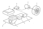
- FIG. 1 is an explanatory diagram schematically showing a system configuration of a hybrid vehicle to which the present invention is applied.
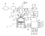
- FIG. 1 is an explanatory diagram schematically showing a system configuration of an internal combustion engine.
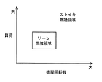
- FIG. 3 is an explanatory diagram schematically showing a setting of a combustion region of the internal combustion engine.
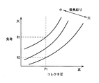
- FIG. 3 is an explanatory diagram schematically showing a correlation between a collector pressure, a load of an internal combustion engine, and an intake throttle.
- FIG. 2 is an explanatory diagram schematically showing a supercharging region of the internal combustion engine.
- 5 is a flowchart illustrating a flow of vehicle control.
- FIG. 1 is an explanatory diagram schematically showing a system configuration of a hybrid vehicle to which the present invention is applied.
- the hybrid vehicle includes a driving wheel 1 of the vehicle, a driving motor 2 for rotating the driving wheel 1, an inverter 3 for supplying AC power to the driving motor 2, a battery 4 for supplying power to the inverter 3, and a power generation unit. And 5.
- the driving wheels 1 of the vehicle are driven to rotate by using the driving motor 2 as a driving source.
- the drive motor 2 corresponds to an electric motor, and is, for example, a synchronous motor using a permanent magnet for a rotor.
- the drive motor 2 is a drive source of the vehicle, and is driven by AC power from the inverter 3.
- the drive motor 2 functions as a generator when the vehicle decelerates. That is, the drive motor 2 can charge the battery 4 via the inverter 3 using the regenerative energy at the time of vehicle deceleration as electric power.
- the inverter 3 is a power conversion circuit that converts the power generated by the power generation unit 5 and the driving motor 2 into DC power and supplies the DC power to the battery 4.
- the inverter 3 is also a power conversion circuit that converts DC power output from the battery 4 into AC power and supplies the AC power to the driving motor 2.
- the battery 4 is a secondary battery that can be charged with the power generated by the power generation unit 5 and the driving motor 2 as DC power.
- the battery 4 supplies the charged power to the driving motor 2 via the inverter 3.
- the power generation unit 5 includes a power generator 6, an internal combustion engine 7 for driving the power generator 6, and a speed reducer 8 arranged between the power generator 6 and the internal combustion engine 7 to connect the two. Have been.
- the internal combustion engine 7 is operated to drive the generator.
- the power generation unit 5 can operate (activate and stop) independently of the drive motor 2.
- the generator 6 is, for example, a synchronous motor using a permanent magnet for the rotor.
- the generator 6 converts the rotational energy generated in the internal combustion engine 7 into electric energy and supplies the electric energy to the battery 4 and the drive motor 2 via the inverter 3.
- the generator 6 also functions as a starter motor when the internal combustion engine 7 starts.
- the reduction gear 8 is equivalent to a gear train, has a plurality of gears (not shown), and transmits the rotation of the internal combustion engine 7 to the generator 6 at a predetermined reduction ratio (rotation speed ratio). I have.
- the reduction gear 8 transmits the rotation of the generator to the internal combustion engine 7 when the generator 6 is used as a starter motor of the internal combustion engine 7.
- FIG. 2 is an explanatory diagram schematically showing the system configuration of the internal combustion engine 7.
- the internal combustion engine 7 is a so-called reciprocating internal combustion engine that converts reciprocating linear motion of the piston 11 into rotational motion of a crankshaft (not shown) and takes out the power as power.
- the internal combustion engine 7 is configured to be able to change the air-fuel ratio. Note that the internal combustion engine 7 may be started by a dedicated starter motor different from the generator 6.
- the internal combustion engine 7 has an intake passage 12 and an exhaust passage 13.
- the intake passage 12 is connected to a combustion chamber 15 via an intake valve 14.
- the exhaust passage 13 is connected to the combustion chamber 15 via an exhaust valve 16.
- the internal combustion engine 7 has a first fuel injection valve 17 for directly injecting fuel (gasoline) into the combustion chamber 15 and a second fuel injection valve 18 for injecting fuel (gasoline) into the intake passage 12 on the upstream side of the intake valve 14. And The fuel injected from the first fuel injection valve 17 and the second fuel injection valve 18 is ignited in the combustion chamber 15 by an ignition plug 19.
- an air cleaner 20 for collecting foreign substances in the intake air an air flow meter 21 for detecting an intake air amount, an electric throttle valve 23 whose opening is controlled by a control signal from a control unit 22, Is provided.
- the air flow meter 21 is disposed upstream of the throttle valve 23.
- the air flow meter 21 has a built-in temperature sensor and can detect the intake air temperature at the intake air inlet.
- the air cleaner 20 is arranged on the upstream side of the air flow meter 21.
- the exhaust passage 13 is provided with an upstream exhaust catalyst device 24 such as a three-way catalyst and a downstream exhaust catalyst device 25 such as a NOx trap catalyst.
- the downstream-side exhaust catalyst device 25 is disposed downstream of the upstream-side exhaust catalyst device 24.
- the internal combustion engine 7 has a supercharger (turbocharger) 28 in which a compressor 26 provided in the intake passage 12 and an exhaust turbine 27 provided in the exhaust passage 13 are coaxially provided. .
- the compressor 26 is disposed upstream of the throttle valve 23 and downstream of the air flow meter 21.
- the exhaust turbine 27 is disposed upstream of the upstream exhaust catalyst device 24.
- a recirculation passage 29 is connected to the intake passage 12. One end of the recirculation passage 29 is connected to the intake passage 12 on the upstream side of the compressor 26, and the other end is connected to the intake passage 12 on the downstream side of the compressor 26.
- An electric recirculation valve 30 capable of releasing the supercharging pressure from the downstream side of the compressor 26 to the upstream side of the compressor 26 is disposed in the recirculation passage 29. It should be noted that a so-called check valve that opens only when the pressure on the downstream side of the compressor 26 becomes equal to or higher than a predetermined pressure can be used as the recirculation valve 30.
- an intercooler 31 is provided downstream of the compressor 26 to cool the intake air compressed (pressurized) by the compressor 26 and improve the charging efficiency.
- the intercooler 31 is located downstream of the downstream end of the recirculation passage 29 and upstream of the throttle valve 23.
- the exhaust passage 13 is connected to an exhaust bypass passage 32 that bypasses the exhaust turbine 27 and connects the upstream side and the downstream side of the exhaust turbine 27.
- the downstream end of the exhaust bypass passage 32 is connected to the exhaust passage 13 at a position upstream of the upstream exhaust catalyst device 24.
- An electric wastegate 33 that controls the flow rate of exhaust gas in the exhaust bypass passage 32 is disposed in the exhaust bypass passage 32. The wastegate 33 can bypass a part of the exhaust gas guided to the exhaust turbine 27 downstream of the exhaust turbine 27 and can control the supercharging pressure of the internal combustion engine 7.
- the intake passage 12 branches on a cylinder downstream side from the collector section 34 as an intake manifold.
- the supercharger 28 is not limited to the turbocharger described above.
- a mechanical supercharger (supercharger) that drives a compressor arranged in the intake passage 12 by the internal combustion engine 7,
- An electric supercharger that drives a compressor disposed in the intake passage 12 with an electric motor may be used.
- the internal combustion engine 7 has an intake-side variable valve mechanism 41 that can change the valve timing (opening / closing timing) of the intake valve 14 as the valve mechanism of the intake valve 14.
- the intake-side variable valve mechanism 41 is a phase variable mechanism that continuously advances or retards the phase of the center angle of the lift of the intake valve 14 (the phase with respect to a crankshaft not shown).
- the variable phase mechanism is known, for example, in Japanese Patent Application Laid-Open No. 2002-89303, and shifts the phase of an intake camshaft 42 that drives the opening and closing of the intake valve 14 with respect to a crankshaft (not shown). It slows down.
- the valve mechanism of the exhaust valve 16 is a general direct-acting valve mechanism. That is, the phase of the lift operation angle and the lift center angle of the exhaust valve 16 are always constant.
- the intake-side variable valve mechanism 41 is, for example, hydraulically driven, and is controlled by a control signal from the control unit 22. That is, the control unit 22 corresponds to a control unit that controls the intake-side variable valve mechanism 41.
- the valve timing of the intake valve 14 can be variably controlled by the control unit 22.
- the intake side variable valve mechanism 41 can change the amount of air in the cylinder by changing the closing timing of the intake valve 14. For example, when the intake valve closing timing is retarded from the bottom dead center, the intake valve closing timing is retarded to be more distant from the bottom dead center so that air is less likely to enter the cylinder. Aperture can be performed.
- the intake-side variable valve mechanism 41 corresponds to an intake throttle that can change the amount of air supplied into the cylinder.
- the intake throttle unit is a component that is located downstream of the throttle valve 23 and that can change the amount of air supplied into the cylinder and can execute an intake throttle that makes it difficult for air to enter the cylinder.
- the intake throttle portion is a component different from the throttle valve 23, and is, for example, a component located downstream of the collector portion 34 and capable of controlling the in-cylinder air amount.
- the intake side variable valve mechanism 41 may be of a type that can independently change the opening timing and the closing timing of the intake valve 14 independently. Further, the intake side variable valve mechanism 41 is not limited to a hydraulically driven type, but may be an electrically driven type by a motor or the like.
- the intake-side variable valve mechanism 41 corresponding to the intake throttle section may be a lift operating angle variable mechanism capable of changing the lift amount and operating angle of the intake valve 14.
- the lift operating angle variable mechanism is already known, for example, from Japanese Patent Application Laid-Open No. 2002-89303, and is capable of simultaneously and continuously increasing and decreasing the lift amount and the operating angle of the intake valve 14.
- the intake-side variable valve mechanism 41 corresponding to the intake throttle section includes a phase variable mechanism for continuously advancing or retarding the phase of the central angle of the lift of the intake valve 14, and a lift amount and operation of the intake valve 14. And a lift operating angle variable mechanism capable of changing the angle.
- the control unit 22 is a well-known digital computer having a CPU, a ROM, a RAM, and an input / output interface.
- the control unit 22 includes, in addition to the detection signal of the air flow meter 21 described above, an intake camshaft position sensor 43 for detecting the valve timing of the intake valve 14, a vehicle speed sensor 44 for detecting the vehicle speed of the vehicle, and a crank angle of the crankshaft. Detection signals of various sensors such as a crank angle sensor 45 for detecting, an accelerator opening sensor 46 for detecting the depression amount of an accelerator pedal, and an intake pressure sensor 47 for detecting a collector pressure which is an intake pressure in the collector section 34 are inputted. I have.
- the intake camshaft position sensor 43 detects the phase of the intake camshaft 42 with respect to the crankshaft.
- the vehicle speed sensor 44 corresponds to a vehicle speed detection unit.
- the crank angle sensor 45 can detect the engine speed of the internal combustion engine 7.
- the accelerator opening sensor 46 can detect an accelerator opening, which is an operation amount of an accelerator pedal, and an accelerator change speed, which is an operation speed of an accelerator pedal. That is, the accelerator opening sensor 46 corresponds to an accelerator operation amount detection unit.
- the crank angle sensor 45 can detect the engine speed of the internal combustion engine 7.
- control unit 22 controls the injection amount and the injection timing of the fuel injected from the first fuel injection valve 17 and the second fuel injection valve 18 based on the detection signals of various sensors, and the internal combustion engine 7 (spark plug 19). In addition to optimally controlling the ignition timing, intake air amount, etc., the air-fuel ratio of the internal combustion engine 7 is controlled.
- the control unit 22 calculates the required load of the internal combustion engine (the load of the internal combustion engine) using the detection value of the accelerator opening sensor 46.
- the control unit 22 can detect SOC (State Of Charge), which is the ratio of the remaining charge to the charge capacity of the battery 4.
- the hybrid vehicle according to the above-described embodiment is a so-called series hybrid vehicle that runs by driving the drive motor 2 with electric power from the generator 6 driven by the internal combustion engine 7 and electric power from the battery 4.
- the series hybrid vehicle drives the internal combustion engine 7 to charge the battery 4.
- the amount of power that can be supplied to the drive motor 2 is determined substantially by the battery capacity of the battery 4 that supplies power to the drive motor 2.
- the battery capacity of the battery 4 that supplies power to the drive motor 2 is often small, and the amount of power from the battery 4 may be limited. Therefore, in a series hybrid vehicle in which the amount of power from the battery 4 is limited, there is a limit in power performance when driving the driving motor 2.
- the internal combustion engine 7 needs to perform a standby operation in which the internal combustion engine 7 is operated in preparation for assisting the power supply to the drive motor 2.
- the vehicle is prepared for assisting the power supply to the driving motor 2, so that the vehicle can be smoothly accelerated when an acceleration is requested.
- the battery capacity of the battery 4 that supplies power to the drive motor 2 is often small. Therefore, in the series hybrid vehicle, if the operating point of the internal combustion engine 7 is operated at the highest thermal efficiency point during the standby operation, the battery 4 will be fully charged in a short time.
- the generated energy is supplied to the drive motor 2 without being stored in the battery 4 as much as possible. Is desirable.
- the series hybrid vehicle can be operated with reduced energy loss related to charge / discharge efficiency if the generator 6 generates power during standby operation by the amount of energy required for traveling.
- a sudden transition of the operating point may cause deterioration of fuel efficiency rather than accuracy of the intake air amount control during the transition of the internal combustion engine 7 and the fuel injection amount control during the transition. That is, during standby operation, there are situations where it is desirable to set the operating point of the internal combustion engine 7 to a lower output operating point.
- the internal combustion engine 7 can suppress the variation in the distribution of the in-cylinder air amount due to the variation in the components of the intake system by pushing air into the cylinder by supercharging by the compressor 26.
- the internal combustion engine 7 cannot perform the lean combustion because the combustion stability cannot be secured, it is necessary to switch to the stoichiometric combustion in which the air-fuel ratio is set to the stoichiometric air-fuel ratio.
- the fuel injection amount is temporarily reduced when the O2 storage amount of the three-way catalyst (upstream exhaust catalyst device 24) installed in the exhaust system of the internal combustion engine 7 becomes excessive. It is necessary to carry out a so-called rich spike to increase the fuel consumption, which causes deterioration of fuel efficiency.
- gear noise may be generated due to torque fluctuation depending on the vehicle or system.
- the gear noise is generated in the speed reducer 8 disposed between the internal combustion engine 7 and the generator 6.
- the muffled noise and gear noise generation area differs depending on the vehicle and system, it is necessary to determine individually whether the specified operating point of the internal combustion engine corresponds to the muffled noise or gear noise generation area for each vehicle or system. There is.
- the standby operation of the internal combustion engine 7 performed in preparation for assisting the power supply to the drive motor 2 is performed on the lower output side than the operating point when the battery 4 is charged, and The operation is performed at an operating point where the collector pressure of the internal combustion engine 7 is equal to or higher than a predetermined collector pressure threshold (intake pressure threshold).
- the operating point is determined by the load of the internal combustion engine 7 and the engine speed of the internal combustion engine.
- a lean combustion operation is performed in which the air-fuel ratio is leaner than the stoichiometric air-fuel ratio. That is, the internal combustion engine 7 is operated at an operating point within a predetermined lean combustion region where the lean combustion operation is performed, as shown in FIG. 3, during a standby operation in preparation for assisting power supply to the drive motor 2.
- the collector pressure threshold is equivalent to the intake pressure threshold.
- the collector pressure threshold is an index of the combustion stability of the internal combustion engine 7, and is obtained in advance by an experiment or the like.
- the collector pressure threshold is a value within the supercharging operation range of the internal combustion engine 7. When the collector pressure becomes lower than the collector pressure threshold, the internal combustion engine 7 may have unstable combustion.
- the standby operation of the internal combustion engine 7, which is performed in preparation for assisting the power supply to the drive motor 2, can improve the acceleration response when an acceleration request is issued.
- the combustion stability of the internal combustion engine 7 during the standby operation can be ensured while suppressing excessive charging during the standby operation.
- the combustion state (combustion stability) of the internal combustion engine 7 may be, for example, a detection signal of a cylinder pressure sensor capable of detecting a cylinder pressure of the internal combustion engine 7 or a sensor (for example, a crank angle) capable of detecting rotation fluctuation of a crankshaft. It is also possible to make the determination using the detection signal of the sensor 45).
- the operating point of the standby operation of the internal combustion engine 7 that is prepared for assisting the power supply to the drive motor 2 is lower than the operating point when the battery 4 is charged, and the combustion stability of the internal combustion engine 7 is reduced. May be an operating point at which is secured.
- the standby operation of the internal combustion engine 7 for assisting the power supply to the drive motor 2 is performed when the vehicle speed of the vehicle is equal to or higher than a predetermined vehicle speed threshold value, and the amount of operation of the accelerator pedal and the accelerator pedal operation. This is performed when at least one of the operation speeds is equal to or higher than a predetermined operation amount threshold or a predetermined operation speed threshold.
- the vehicle speed threshold may be determined in consideration of the weight of the vehicle. For example, the vehicle speed threshold value is set to a smaller value as the vehicle weight increases. Further, the weight of the vehicle may be detected during traveling by the vehicle weight detection unit.
- the vehicle weight detection unit detects, for example, a suspension stroke or the like by a sensor and detects the vehicle weight from the degree of sinking of the vehicle when the vehicle stops.
- the operating point of the internal combustion engine 7 at the time of performing the standby operation of the internal combustion engine 7 in preparation for assisting the power supply to the drive motor 2 is such that the SOC of the battery 4 becomes lower than a predetermined SOC threshold and the battery 4 is charged.
- the load is lower than the operating point at the time.
- the engine speed of the internal combustion engine may be reduced with a predetermined speed threshold value as a lower limit.
- the output generated by the internal combustion engine 7 during the standby operation of the internal combustion engine 7 provided to assist the power supply to the drive motor 2 is equivalent to the amount of power consumed by the drive motor 2 during the standby operation. It may be output.
- the standby operation can be performed without increasing the SOC of the battery 4.
- the collector pressure threshold may be set in a supercharging region where supercharging is performed by the supercharger 28.
- the supercharging pressure acts to reduce variations in the distribution of various air downstream of the supercharger 28. Stable lean combustion can be achieved.
- the intake-side variable valve mechanism 41 is controlled so that air does not easily enter the cylinder of the internal combustion engine 7. At the same time, supercharging by the supercharger 28 may be performed.
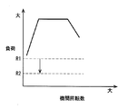
- FIG. 4 is an explanatory diagram schematically showing the correlation between the collector pressure, the load of the internal combustion engine 7, and the intake throttle.
- the combustion stability of the internal combustion engine 7 deteriorates when the collector pressure falls below a predetermined combustion stability threshold P1.
- P1 combustion stability threshold
- the collector pressure can be increased without changing the amount of air in the cylinder.
- the amount of air in the cylinder can be reduced without changing the collector pressure.
- the lower limit value of the load of the internal combustion engine 7 that becomes the combustion stability threshold value P1 is shown in FIGS. As shown, it decreases from R1 to R2.
- the supercharging region of the internal combustion engine 7 is reduced as shown by the broken line in FIG. It can be expanded to the load side.
- the collector pressure is equal to or higher than the atmospheric pressure.
- the operating point of the internal combustion engine 7 is set to the noise level. It may move out of the vibration deterioration area.
- the operating point is moved to the high rotation side.
- the operating region of the internal combustion engine 7 where the muffled sound is generated can be specified in advance by the engine speed and the load.
- the operating point of the internal combustion engine 7 moves to the outside of the operating region where the muffled sound is generated. Therefore, the vehicle can suppress noise and vibration caused by the muffled sound.
- the operating range of the internal combustion engine 7 where gear noise occurs can be specified in advance by the engine speed and load.
- the operating point of the internal combustion engine 7 moves outside the operating region where gear noise occurs. Therefore, the vehicle can suppress noise and vibration caused by gear noise.
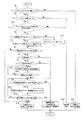
- FIG. 6 is a flowchart showing the flow of control of the vehicle in the embodiment described above. This routine is repeatedly executed by the control unit 22 every predetermined time (for example, every 10 ms).
- step S1 it is determined whether or not the SOC of the battery 4 is equal to or greater than the SOC threshold. If the SOC of the battery 4 is equal to or greater than the SOC threshold in step S1, the process proceeds to step S2. If the SOC of the battery 4 is less than the SOC threshold in step S1, the process proceeds to step S15. In step S15, the internal combustion engine 7 is operated at the operating point for charging.
- the operating point for charging is an operating point with good fuel efficiency.
- the operating point in the stoichiometric combustion region where the stoichiometric combustion is performed may be selected as the operating point for charging.
- the operating point for charging set in step S15 is basically an operating point in the lean combustion region, but when the output demand of the internal combustion engine 7 is high, the operating point is in the stoichiometric combustion region.
- step S15 If the process proceeds to step S15 with the internal combustion engine 7 stopped, the internal combustion engine 7 starts operating at the charging operating point in step S15.
- step S2 it is determined whether the vehicle speed is equal to or higher than a vehicle speed threshold. If the vehicle speed is equal to or higher than the vehicle speed threshold in step S2, the process proceeds to step S3. If the vehicle speed is less than the vehicle speed threshold value in step S1, the process proceeds to step S16. In step S16, the internal combustion engine 7 is stopped.
- step S16 If the process proceeds to step S16 with the internal combustion engine 7 stopped, the internal combustion engine 7 maintains the stopped state in step S16.
- the electric power required by the drive motor 2 can be reduced. That is, when the vehicle speed is lower than the vehicle speed threshold, the power required by the drive motor 2 can be stably supplied only by the power charged in the battery 4. Therefore, when the vehicle speed is lower than the vehicle speed threshold, the standby operation of the internal combustion engine 7 for assisting the power supply to the drive motor 2 is not necessary.
- step S3 it is determined whether the accelerator opening as the accelerator opening or the accelerator changing speed is equal to or greater than a predetermined threshold. That is, it is determined whether the accelerator opening is equal to or greater than a predetermined opening threshold or whether the accelerator opening speed is equal to or greater than a predetermined opening speed threshold.
- the accelerator opening speed is the speed at which the accelerator changes when the accelerator pedal is depressed.
- step S3 If the accelerator opening or the accelerator opening speed is equal to or larger than the predetermined threshold in step S3, the process proceeds to step S4. If the accelerator opening or the accelerator opening speed is less than the predetermined threshold value in step S3, it is determined that the driver's acceleration request is small and it is not necessary to perform the standby operation, and the process proceeds to S16.
- step S4 it is determined whether the load on the internal combustion engine 7 is equal to or greater than a predetermined gear noise lower limit.
- the gear noise lower limit value is an upper limit value of a load in an operation region where gear noise occurs (gear noise occurrence region). That is, in an operating region where the load on the internal combustion engine 7 is less than the gear noise lower limit, gear noise may be generated in the speed reducer 8.
- step S5 If the load of the internal combustion engine 7 is equal to or higher than the gear noise lower limit value in step S4, the process proceeds to step S5. That is, when it is possible to reduce the load on the internal combustion engine 7 within a range where the gear noise is not generated in the speed reducer 8, the process proceeds from step S4 to step S5. If the load on the internal combustion engine 7 is less than the gear noise lower limit value in step S4, the process proceeds to step S17.
- step S17 the load of the internal combustion engine 7 is set to the gear noise lower limit.
- the load of the internal combustion engine 7 is less than the gear noise lower limit, the generation of gear noise can be suppressed by setting the load of the internal combustion engine 7 to the gear noise lower limit.
- step S5 the target load at the operating point in the standby operation of the internal combustion engine 7 is reduced by a predetermined amount so that the combustion stability of the internal combustion engine 7 is ensured. Specifically, the load on the internal combustion engine 7 is reduced so that the collector pressure does not become lower than the collector pressure threshold.
- step S5 for example, the load on the internal combustion engine 7 may be reduced so that power generation corresponding to the amount of power consumed by the drive motor 2 is enabled. Further, the amount of decrease in the load in step S5 may be set according to the power consumption of the driving motor 2, the minimum output load and the rotation permitted in the current driving situation, and the like.
- step S6 it is determined whether or not the output of the internal combustion engine 7 needs to be further reduced. More specifically, is it necessary to further reduce the output of the internal combustion engine 7 based on at least two of the SOC of the battery 4, the amount of power used by the drive motor 2, and the amount of power generated by the generator 6. Determine whether or not. Specifically, when the SOC of the battery 4 increases, or when the amount of power generation is larger than the amount of power consumed by the drive motor 2, the output of the internal combustion engine 7 is further increased to avoid charging the battery 4. It is determined that lowering is necessary.
- step S6 If it is determined in step S6 that the output of the internal combustion engine 7 needs to be further reduced, the process proceeds to step S7. If it is determined in step S6 that further reduction in the output of the internal combustion engine 7 is not necessary, the process proceeds to step S14.
- step S7 it is determined whether or not the internal combustion engine 7 has the supercharger 28.
- the process proceeds to step S8. If the internal combustion engine 7 does not have the supercharger 28, the process proceeds to step S11.
- step S8 it is determined whether or not the internal combustion engine 7 has an intake throttle. If the internal combustion engine 7 has an intake throttle section (for example, the intake-side variable valve mechanism 41), the process proceeds to step S9. When the internal combustion engine 7 does not have the intake throttle section (for example, the intake-side variable valve mechanism 41), the process proceeds to step S11.
- step S9 intake air is throttled by an intake throttle unit (for example, the intake-side variable valve mechanism 41), and the supercharging region by the supercharger 28 is expanded to a low load side.
- an intake throttle unit for example, the intake-side variable valve mechanism 41
- the intake valve closing timing is delayed from the bottom dead center
- the intake valve is closed by delaying the intake valve closing timing by a predetermined amount (the intake throttle is performed).
- the intake valve closing timing is advanced from the bottom dead center, the intake valve is closed by advancing the intake valve closing timing by a predetermined amount (the intake throttle is performed).
- step S10 it is determined whether or not the supercharging region has reached the expansion limit. That is, when the intake air can be further throttled by the intake-side variable valve mechanism 41 so that the collector pressure does not become equal to or lower than the collector pressure threshold, the process proceeds to step S9. If it is not possible to further restrict the intake by the intake-side variable valve mechanism 41 so that the collector pressure does not fall below the collector pressure threshold, the process proceeds to step S11.
- step S11 it is determined whether or not the engine speed of the internal combustion engine 7 is equal to or higher than a preset muffled sound rotation threshold value.
- the muffled sound rotation threshold value is an upper limit value of the engine speed in an operation region where the muffled sound is generated (muffled sound generation region). That is, in an operating region where the engine speed of the internal combustion engine 7 is lower than the muffled sound rotation threshold, muffled sound may be generated.
- step S11 If the engine speed of the internal combustion engine 7 is equal to or higher than the muffled sound rotation threshold value in step S11, the process proceeds to step S12. That is, when it is possible to reduce the engine speed of the internal combustion engine 7 within a range in which the muffled sound is not generated, the process proceeds from step S11 to step S12. If the engine speed of the internal combustion engine 7 is less than the muffled sound rotation threshold value in step S11, the process proceeds to step S18.
- step S18 the engine speed of the internal combustion engine 7 is set to the muffled sound rotation threshold value, and the load of the internal combustion engine 7 is set to the value set in the current routine to perform the standby operation of the internal combustion engine 7.
- the engine speed of the internal combustion engine 7 is less than the muffled sound rotation threshold value, the occurrence of muffled sound can be suppressed by setting the rotation speed of the internal combustion engine 7 to the muffled sound rotation threshold value.
- step S18 the internal combustion engine 7 performs standby operation at the operating point set in this routine.
- the operating point of the standby operation performed in step S18 is an operating point in the lean combustion region.
- step S18 If the process proceeds to step S18 while the internal combustion engine 7 is stopped, the internal combustion engine 7 starts standby operation in step S18.
- step S12 the rotation speed of the generator 6 is reduced, and the output of the internal combustion engine 7 is reduced. That is, in step S12, the output of the internal combustion engine 7 is reduced by reducing the target engine speed at the operating point in the standby operation of the internal combustion engine 7 by a predetermined amount. Specifically, the engine speed of the internal combustion engine 7 is reduced so that the collector pressure does not become lower than the collector pressure threshold.
- step S12 for example, the engine speed of the internal combustion engine 7 may be reduced so that power generation corresponding to the amount of power consumed by the drive motor 2 is enabled. Further, the amount of decrease in the engine speed in step S12 may be set in accordance with the power consumption of the drive motor 2, the load and the rotation at which the minimum output is permitted in the current driving situation, and the like.
- step S13 it is determined whether the output of the internal combustion engine 7 needs to be further reduced. More specifically, is it necessary to further reduce the output of the internal combustion engine 7 based on at least two of the SOC of the battery 4, the amount of power used by the drive motor 2, and the amount of power generated by the generator 6. Determine whether or not. Specifically, when the SOC of the battery 4 increases, or when the amount of power generation is larger than the amount of power consumed by the drive motor 2, the output of the internal combustion engine 7 is further increased to avoid charging the battery 4. It is determined that lowering is necessary.
- step S13 If it is determined in step S13 that the output of the internal combustion engine 7 needs to be further reduced, the process proceeds to step S11. If it is determined in step S13 that the output of the internal combustion engine 7 does not need to be further reduced, the process proceeds to step S14.
- step S14 the internal combustion engine 7 performs standby operation at the operating point set in the current routine.
- the operating point of the standby operation performed in step S14 is an operating point in the lean combustion region. If the process proceeds to step S14 while the internal combustion engine 7 is stopped, the internal combustion engine 7 starts standby operation in step S14.
- the load is reduced before the engine speed is reduced. You may.
- the output of the internal combustion engine 7 can be reduced with higher responsiveness when the load is reduced than when the engine speed is reduced.
- the embodiments described above relate to a vehicle control method and a vehicle control device.
Landscapes
- Engineering & Computer Science (AREA)
- Transportation (AREA)
- Mechanical Engineering (AREA)
- Chemical & Material Sciences (AREA)
- Combustion & Propulsion (AREA)
- Automation & Control Theory (AREA)
- Hybrid Electric Vehicles (AREA)
- Electric Propulsion And Braking For Vehicles (AREA)
Abstract
内燃機関(7)は発電機(6)を駆動する。内燃機関(7)は、待機運転を行う。待 機運転は、駆動用モータ(2)への電力供給補助に備えた運転である。内燃機関(7 )の待機運転が行われる時には、バッテリ(4)のSOCが所定のSOC閾値以上の 状態になっている。待機運転時の内燃機関(7)の運転点は、バッテリ(4)を充電 する際の運転点よりも低出力側である。待機運転時の内燃機関(7)の運転点は、内 燃機関(7)のコレクタ圧が所定のコレクタ圧閾値以上となる運転点である。待機運 転時における内燃機関(7)の運転点は、リーン燃焼領域内の運転点である。
Description
本発明は、車両の制御方法及び車両の制御装置に関する。
例えば、特許文献1には、車両駆動用の電動モータと、発電用の内燃機関と、を有するハイブリッド車両において、発電のための内燃機関の運転が不要とされた場合に、内燃機関を所定の待機運転で運転している。
特許文献1における内燃機関の待機運転は、負荷及び機関回転数が小さい運転領域またはリーン燃焼が行われる運転領域において行うものである。
しかしながら、この特許文献1においては、待機運転時にリーン燃焼が行われる運転領域を使用する場合の内燃機関の運転点(負荷と機関回転数)に関する開示がない。
バッテリのSOCが高く、バッテリの過充電を避けつつ待機運転を行う場合、ストイキ燃焼のときと同様に内燃機関の出力(負荷または機関回転数)を単純に下げると、筒内ガス流動の悪化から燃焼が不安定となり、排気性能の悪化を招く虞がある。
本発明の車両は、発電した電力をバッテリに供給可能な発電機と、車両の駆動源であり、上記バッテリまたは上記発電機からの電力により駆動する電動機と、上記発電機を駆動し、空燃比を変更可能な内燃機関と、を有する。
そして、上記バッテリのSOCが所定のSOC閾値以上の状態で上記電動機への電力供給補助に備えて上記内燃機関の待機運転を行う場合、上記バッテリのSOCが上記SOC閾値未満となって上記バッテリを充電する際の運転点よりも低出力側で、かつ上記内燃機関の吸気圧が所定の吸気圧閾値以上となる運転点でリーン燃焼運転を行う。
これによって、加速要求があった際の加速応答性を向上させる待機運転は、待機運転中の過度な充電の抑制しつつ、待機運転中の内燃機関の燃焼安定性を確保することができる。
以下、本発明の一実施例を図面に基づいて詳細に説明する。
図1は、本発明が適用されるハイブリッド車両のシステム構成を模式的に示した説明図である。
ハイブリッド車両は、車両の駆動輪1と、駆動輪1を回転駆動させる駆動用モータ2と、駆動用モータ2に交流電力を供給するインバータ3と、インバータ3に電力を供給するバッテリ4及び発電ユニット5と、を有している。
車両の駆動輪1は、駆動用モータ2を駆動源として回転駆動する。
駆動用モータ2は、電動機に相当するものであって、例えば、ロータに永久磁石を用いた同期型モータからなっている。
駆動用モータ2は、車両の駆動源であり、インバータ3からの交流電力により駆動する。また、駆動用モータ2は、車両の減速時に発電機として機能する。すなわち、駆動用モータ2は、車両減速時の回生エネルギーを電力としてインバータ3を介してバッテリ4に充電可能となっている。
インバータ3は、発電ユニット5や駆動用モータ2で発電された電力を直流電力に変換してバッテリ4に供給する電力変換回路である。また、インバータ3は、バッテリ4から出力される直流電力を交流電力に変換して駆動用モータ2に供給する電力変換回路でもある。
バッテリ4は、発電ユニット5や駆動用モータ2で発電された電力を直流電力として充電可能な二次電池である。バッテリ4は、充電された電力をインバータ3を介して駆動用モータ2に供給する。
発電ユニット5は、発電機6と、発電機6を駆動する発電用の内燃機関7と、発電機6と内燃機関7との間に配置され、両者を連結する減速機8と、から大略構成されている。
つまり、本発明が適用されるハイブリッド車両は、内燃機関7が発電機を駆動するために運転される。
発電ユニット5は、駆動用モータ2とは独立した動作(作動及び停止)が可能となっている。
発電機6は、例えば、ロータに永久磁石を用いた同期型モータからなっている。
発電機6は、内燃機関7に発生した回転エネルギーを電気エネルギーに変換し、インバータ3を介してバッテリ4や駆動用モータ2に供給する。また、発電機6は、内燃機関7の始動時にスタータモータとしても機能する。
減速機8は、歯車列に相当するものであって、複数の歯車(図示せず)を有し、所定の減速比(回転数比)で内燃機関7の回転を発電機6に伝達している。なお、減速機8は、発電機6を内燃機関7のスタータモータとして使用する場合、発電機の回転を内燃機関7に伝達する。
図2は、内燃機関7のシステム構成を模式的に示した説明図である。
内燃機関7は、ピストン11の往復直線運動をクランクシャフト(図示せず)の回転運動に変換して動力として取り出すいわゆるレシプロ式の内燃機関である。内燃機関7は、空燃比を変更可能に構成されている。なお、内燃機関7は、発電機6とは異なる専用のスタータモータにより始動するようにしてもよい。
内燃機関7は、吸気通路12と排気通路13とを有している。吸気通路12は、吸気弁14を介して燃焼室15に接続されている。排気通路13は、排気弁16を介して燃焼室15に接続されている。
内燃機関7は、燃焼室15内に燃料(ガソリン)を直接噴射する第1燃料噴射弁17と、吸気弁14上流側の吸気通路12内に燃料(ガソリン)を噴射する第2燃料噴射弁18と、を有している。第1燃料噴射弁17及び第2燃料噴射弁18から噴射された燃料は、燃焼室15内で点火プラグ19により点火される。
吸気通路12には、吸気中の異物を捕集するエアクリーナ20と、吸入空気量を検出するエアフローメータ21と、コントロールユニット22からの制御信号によって開度が制御される電動のスロットル弁23と、が設けられている。
エアフローメータ21は、スロットル弁23の上流側に配置されている。エアフローメータ21は、温度センサを内蔵したものであって、吸気導入口の吸気温度を検出可能となっている。エアクリーナ20は、エアフローメータ21の上流側に配置されている。
排気通路13には、三元触媒等の上流側排気触媒装置24と、NOxトラップ触媒等の下流側排気触媒装置25と、が設けられている。下流側排気触媒装置25は、上流側排気触媒装置24の下流側に配置されている。
また、この内燃機関7は、吸気通路12に設けられたコンプレッサ26と排気通路13に設けられた排気タービン27とを同軸上に備えた過給機(ターボ過給機)28を有している。コンプレッサ26は、スロットル弁23の上流側で、かつエアフローメータ21よりも下流側に配置されている。排気タービン27は、上流側排気触媒装置24よりも上流側に配置されている。
吸気通路12には、リサーキュレーション通路29が接続されている。リサーキュレーション通路29は、その一端がコンプレッサ26の上流側で吸気通路12に接続され、その他端がコンプレッサ26の下流側で吸気通路12に接続されている。
このリサーキュレーション通路29には、コンプレッサ26の下流側からコンプレッサ26の上流側へ過給圧を解放可能な電動のリサーキュレーション弁30が配置されている。なお、リサーキュレーション弁30としては、コンプレッサ26下流側の圧力が所定圧力以上となったときのみ開弁するようないわゆる逆止弁を用いることも可能である。
また、吸気通路12には、コンプレッサ26の下流側に、コンプレッサ26により圧縮(加圧)された吸気を冷却して充填効率を良くするインタクーラ31が設けられている。インタクーラ31は、リサーキュレーション通路29の下流側端よりも下流で、スロットル弁23よりも上流側に位置している。
排気通路13には、排気タービン27を迂回して排気タービン27の上流側と下流側とを接続する排気バイパス通路32が接続されている。排気バイパス通路32の下流側端は、上流側排気触媒装置24よりも上流側の位置で排気通路13に接続されている。排気バイパス通路32には、排気バイパス通路32内の排気流量を制御する電動のウエストゲート33が配置されている。ウエストゲート33は、排気タービン27に導かれる排気ガスの一部を排気タービン27の下流側にバイパスさせることが可能であり、内燃機関7の過給圧を制御可能なものである。
なお、図1中の34は、吸気通路12のコレクタ部である。吸気通路12は、内燃機関7が多気筒内燃機関であれば、コレクタ部34よりも下流側が吸気マニホールドとして気筒毎に分岐する。
また、過給機28は、上述したターボ過給機に限定されるものではなく、例えば吸気通路12内に配置されたコンプレッサを内燃機関7によって駆動する機械式過給機(スーパーチャージャ)や、吸気通路12内に配置されたコンプレッサを電動モータで駆動する電動過給機であってもよい。
内燃機関7は、吸気弁14の動弁機構として、吸気弁14のバルブタイミング(開閉時期)を変更可能な吸気側可変動弁機構41を有している。
吸気側可変動弁機構41は、吸気弁14のリフトの中心角の位相(図示せぬクランクシャフトに対する位相)を連続的に進角もしくは遅角させる位相可変機構である。位相可変機構は、例えば、特開2002−89303号公報等によって既に公知となっているものであり、吸気弁14を開閉駆動する吸気カムシャフト42の位相をクランクシャフト(図示せず)に対して遅進させるものである。
なお、排気弁16の動弁機構は、一般的な直動式の動弁機構である。つまり、排気弁16のリフト作動角やリフト中心角の位相は、常に一定である。
吸気側可変動弁機構41は、例えば油圧駆動されるものであって、コントロールユニット22からの制御信号によって制御される。つまり、コントロールユニット22は、吸気側可変動弁機構41を制御する制御部に相当するものである。そして、コントロールユニット22によって、吸気弁14のバルブタイミングを可変制御することが可能となっている。吸気側可変動弁機構41は、吸気弁14の閉弁時期を変更することで、筒内の空気量を変更することが可能となっている。例えば、吸気弁閉時期が下死点よりも遅角しているような場合には、吸気弁閉時期を遅角させて下死点よりも遠ざけることで、筒内に空気が入りにくくなる吸気絞りを実行できる。また、例えば、吸気弁閉時期が下死点よりも進角しているような場合には、吸気弁閉時期を進角させて下死点よりも遠ざけることで、筒内に空気が入りにくくなる吸気絞りを実行できる。つまり、吸気側可変動弁機構41は、筒内に供給される空気量を変更可能な吸気絞り部に相当する。すなわち、吸気絞り部とは、スロットル弁23の下流側に位置して筒内に供給される空気量を変更可能で、筒内に空気が入りにくくなる吸気絞りを実行可能な構成要素である。換言すれば、吸気絞り部とは、スロットル弁23とは異なる構成要素であり、例えば、コレクタ部34の下流側に位置して筒内空気量をコントロール可能な構成要素である。
吸気側可変動弁機構41は、吸気弁14の開時期及び閉時期を個々に独立して変更できる形式のものでもよい。また、吸気側可変動弁機構41は、油圧駆動されるものに限定されるものではなく、モータ等による電動駆動のものであってもよい。
なお、吸気絞り部に相当する吸気側可変動弁機構41は、吸気弁14のリフト量及び作動角を変更可能なリフト作動角可変機構であってもよい。リフト作動角可変機構は、例えば、特開2002−89303号公報等によって既に公知となっているものであり、吸気弁14のリフト量と作動角を同時にかつ連続的に拡大、縮小させるものある。
吸気側可変動弁機構41がリフト作動角可変機構の場合には、吸気弁14の小リフト量化や小作動角化等によって、筒内に空気を入りにくくすることができる。
また、吸気絞り部に相当する吸気側可変動弁機構41は、吸気弁14のリフトの中心角の位相を連続的に進角もしくは遅角させる位相可変機構と、吸気弁14のリフト量及び作動角を変更可能なリフト作動角可変機構と、から構成するようにしてもよい。
コントロールユニット22は、CPU、ROM、RAM及び入出力インターフェースを備えた周知のデジタルコンピュータである。
コントロールユニット22には、上述したエアフローメータ21の検出信号のほか、吸気弁14のバルブタイミングを検出する吸気側カムシャフトポジションセンサ43、車両の車速を検出する車速センサ44、クランクシャフトのクランク角を検出するクランク角センサ45、アクセルペダルの踏込量を検出するアクセル開度センサ46、コレクタ部34における吸気圧であるコレクタ圧を検出する吸気圧センサ47等の各種センサ類の検出信号が入力されている。
吸気側カムシャフトポジションセンサ43は、吸気カムシャフト42のクランクシャフトに対する位相を検出するものである。
車速センサ44は、車速検出部に相当するものである。
クランク角センサ45は、内燃機関7の機関回転速度を検出可能なものである。
アクセル開度センサ46は、アクセルペダルの操作量であるアクセル開度のほか、アクセルペダルの操作速度であるアクセル変化速度を検出可能なものである。つまり、アクセル開度センサ46は、アクセル操作量検出部に相当する。
クランク角センサ45は、内燃機関7の機関回転速度を検出可能なものである。
そして、コントロールユニット22は、各種センサ類の検出信号に基づいて、第1燃料噴射弁17、第2燃料噴射弁18から噴射される燃料の噴射量や噴射時期、内燃機関7(点火プラグ19)の点火時期、吸入空気量等を最適に制御するとともに、内燃機関7の空燃比を制御している。
コントロールユニット22は、アクセル開度センサ46の検出値を用いて、内燃機関の要求負荷(内燃機関の負荷)が算出する。
また、コントロールユニット22は、バッテリ4の充電容量に対する充電残量の比率であるSOC(State Of Charge)を検出可能となっている。
上述した実施例のハイブリッド車両は、内燃機関7により駆動される発電機6からの電力及びバッテリ4からの電力により駆動用モータ2を駆動して走行するいわゆるシリーズハイブリッド車両である。シリーズハイブリッド車両は、バッテリ4のSOCが低くなると、当該バッテリ4を充電するために内燃機関7を駆動する。
シリーズハイブリッド車両では、駆動用モータ2に対して供給可能な電力量が概ね当該駆動用モータ2に電力を供給するバッテリ4のバッテリ容量で決まる。シリーズハイブリッド車両の場合、駆動用モータ2に電力を供給するバッテリ4のバッテリ容量が小さいことが多く、バッテリ4からの電力量に制限が発生することがある。そのため、バッテリ4からの電力量に制限があるシリーズハイブリッド車両においては、駆動用モータ2を運転するにあたって、動力性能に限界がある。
シリーズハイブリッド車両においては、駆動用モータ2に大出力が求められた際、バッテリ4からの電力に加え、内燃機関7を運転して発電機6で発電した電力の補助が必要になる。
しかしながら、内燃機関7が停止している状態では、駆動用モータ2に大出力が求められても内燃機関7は瞬時に所望の出力を発生させることはできない。つまり、加速要求を受けてから内燃機関7を始動する場合には、内燃機関7が所望の出力を発生するまで車両の動力性能に悪影響を及ぼす虞がある。
そこで、内燃機関7には、加速要求により駆動用モータ2の出力要求が増加した場合を考慮し、駆動用モータ2への電力供給補助に備えて運転する待機運転が必要とされる。
このような待機運転では、基本的には、バッテリ4から供給される電力と、内燃機関7を動かして発電機6で発電した電力と、を合わせた電力が駆動用モータ2に供給される。
この待機運転中は、駆動用モータ2への電力供給補助に備えているため、加速要求があった場合に車両のスムースな加速を実現できる。
また、シリーズハイブリッド車両においては、駆動用モータ2に電力を供給するバッテリ4のバッテリ容量が小さいことが多い。そのため、シリーズハイブリッド車両においては、待機運転中に内燃機関7の運転点を最高熱効率点で運転すると、短時間でバッテリ4が満充電となってしまう。
待機運転中にバッテリ4が満充電とならないようにするためには、待機運転における内燃機関7の運転点を熱効率が最もよくなるような運転点ではなく、出力が低くなる運転点とすることが有効である。
なお、シリーズハイブリッド車両においては、駆動用モータ2に電力を供給するバッテリ4の充放電効率を考慮すると、発電したエネルギーをバッテリ4に極力蓄えずにそのまま駆動用モータ2に供給して使用することが望ましい。
シリーズハイブリッド車両は、待機運転中、走行に必要なエネルギーの分だけ発電機6で発電するようにすれば、充放電効率に関するエネルギー損失を抑制して運転できる。
ただし、運転点の急減な遷移は、内燃機関7の過渡時の吸入空気量制御及び過渡時の燃料噴射量制御の精度によってはかえって燃費悪化の原因となることもある。つまり、待機運転中は、内燃機関7の運転点をより低出力の運転点にすることが望ましい場面も存在する。
内燃機関7の出力を低下させる手法としては、機関回転数を下げること、負荷を下げること、機関回転数と負荷を下げること等が考えられる。
ここで、低負荷低回転運転は、筒内のガス流動が悪化しやすく理想的な燃焼になりにくいことが知られている。特に、高希薄燃焼となるリーン燃焼は、筒内のガス流動による燃焼安定性の確保がリーン燃焼の成立に大きな影響を及ぼす。すなわち、リーン燃焼中の内燃機関7は、燃焼安定性が悪化すると排気性能の悪化に繋がるため、負荷及び機関回転数の制約を持たせる必要がある。
リーン燃焼中の内燃機関7の負荷及び機関回転数の制約は、内燃機関7の仕様により異なる。そのため、リーン燃焼中の内燃機関7の負荷及び機関回転数の各閾値は、適合時に個別に確認して設定することになる。また、内燃機関7は、燃焼安定性を常にモニタリングすることで燃焼安定性が確保できる負荷及び機関回転数で運転することになることが望ましい。
内燃機関7は、コンプレッサ26による過給で筒内に空気を押し込むことで、吸気系の部品ばらつきによる筒内空気量の分配ばらつきを抑制できることが知られている。
過給機28付きの内燃機関7においては、筒内空気量の分配ばらつきの抑制により燃焼安定性が確保し易くなるため、過給領域でリーン燃焼を行うことが望ましい。
また、内燃機関7は、燃焼安定性が確保できないことによりリーン燃焼が行えない場合、空燃比を理論空燃比とするストイキ燃焼に切り替える必要がある。ただし、ストイキ燃焼を行った場合には、内燃機関7の排気系に設置された三元触媒(上流側排気触媒装置24)のO2ストレージ量が過大となった際に燃料噴射量を一時的に増量するいわゆるリッチスパイクを実施する必要があり、燃費が悪化する原因となる。
機関回転数を下げて内燃機関7の出力を低下させる場合には、車両やシステムによっては車室内にこもり音が発生する虞がある。
内燃機関7の負荷を下げて内燃機関7の出力を低下させる場合には、車両やシステムによってはトルク変動を起因としたギヤノイズが発生する虞がある。ギヤノイズは、内燃機関7と発電機6の間に配置される減速機8に発生するものである。
そのため、内燃機関7の機関回転数や負荷を下げて内燃機関7の出力を低下させる場合には、機関回転数や負荷の下げ方を車両に応じて制御することで、こもり音やギヤノイズの発生を抑制して、音振性能の悪化を抑制する必要がある。
こもり音やギヤノイズの発生領域は、車両やシステムにより異なるので、指示された内燃機関の運転点がこもり音やギヤノイズの発生領域に該当するか否かは各車両やシステム毎に個別に判断する必要がある。
そこで、上述した実施例のシリーズハイブリッド車両において、駆動用モータ2への電力供給補助に備えて行う内燃機関7の待機運転は、バッテリ4を充電する際の運転点よりも低出力側で、かつ内燃機関7のコレクタ圧が所定のコレクタ圧閾値(吸気圧閾値)以上となる運転点で実施する。
ここで、運転点は、内燃機関7の負荷と内燃機関の機関回転数によって決まるものとする。
また、駆動用モータ2への電力供給補助に備えて行う内燃機関7の待機運転中は、空燃比が理論空燃比よりもリーンとなるリーン燃焼運転を行う。すなわち、内燃機関7は、駆動用モータ2への電力供給補助に備えた待機運転時に、図3に示すように、リーン燃焼運転を実施する所定のリーン燃焼領域内の運転点で運転される。
コレクタ圧閾値は、吸気圧閾値に相当するものである。コレクタ圧閾値は、内燃機関7の燃焼安定性の指標であり、予め実験等により求められる。コレクタ圧閾値は、内燃機関7の過給運転領域内にある値である。内燃機関7は、コレクタ圧がコレクタ圧閾値未満になると、燃焼が不安定になる虞がある。
これによって、駆動用モータ2への電力供給補助に備えて行う内燃機関7の待機運転は、加速要求があった際の加速応答性を向上させることができる。また、この待機運転は、待機運転中の過度な充電の抑制しつつ、待機運転中の内燃機関7の燃焼安定性を確保することができる。
なお、内燃機関7の燃焼状態(燃焼安定性)は、例えば、内燃機関7の筒内圧力を検出可能な筒内圧センサの検出信号や、クランクシャフトの回転変動を検出可能なセンサ(例えばクランク角センサ45)の検出信号を用いて判定することも可能である。
筒内圧センサを用いた場合には、リアルタイムで検出される筒内圧力を用いた燃焼解析により内燃機関の燃焼状態が安定しているか否かを判定可能である。
クランクシャフトの回転変動を検出可能なセンサを用いた場合には、クランクシャフトの角速度変化から内燃機関の燃焼状態が安定しているか否かを判定可能である。例えば、クランクシャフトの角速度の変化量が所定の角速度変化閾値以下のときに、内燃機関7の燃焼状態が安定していると判定してもよい。
つまり、駆動用モータ2への電力供給補助に備えて行う内燃機関7の待機運転の運転点は、バッテリ4を充電する際の運転点よりも低出力側で、かつ内燃機関7の燃焼安定性が確保される運転点であってもよい。
駆動用モータ2への電力供給補助に備えた内燃機関7の待機運転は、詳述すると、車両の車速が予め設定された所定の車速閾値以上となり、かつ、アクセルペダルの操作量とアクセルペダルの操作速度の少なくとも一方が所定の操作量閾値または所定の操作速度閾値以上である場合に行われる。
なお、車速閾値は、車両の重量を考慮して決定するようにしてもよい。例えば、車速閾値は、車両の車重が重くなるほど、小さい値に設定される。また、車両の重量は、車両重量検出部により走行中に検出するようにしてもよい。車両重量検出部は、例えば、サスペンションストローク等をセンサで検出し、車両停止時において車両の沈み込み具合から車両重量を検出するものである。
また、駆動用モータ2への電力供給補助に備えた内燃機関7の待機運転を行う際の内燃機関7の運転点は、バッテリ4のSOCが所定のSOC閾値未満となってバッテリ4を充電する際の運転点よりも低負荷側となっている。
これによって、内燃機関7は、出力を低下させることができる。
さらに、駆動用モータ2への電力供給補助に備えた内燃機関7の待機運転は、所定の回転数閾値を下限として上記内燃機関の機関回転数を低下させてもよい。
これによっても、内燃機関は、出力を低下させることができる。
また、駆動用モータ2への電力供給補助に備えた内燃機関7の待機運転中に内燃機関7で発生させる出力は、当該待機運転中に駆動用モータ2で消費する電力量に相当する分の出力としてもよい。
この場合には、バッテリ4のSOCを増加させずに待機運転を行うことができる。
コレクタ圧閾値は、過給機28により過給が行われる過給領域に設定してもよい。
この場合、内燃機関7は、駆動用モータ2への電力供給補助に備えた待機運転中、過給圧が作用することで過給機28の下流側における各種空気分配のばらつきが低減し、より安定したリーン燃焼を実現できる。
また、駆動用モータ2への電力供給補助に備えた内燃機関7の待機運転を行う際には、内燃機関7の筒内に空気が入りにくくなるように吸気側可変動弁機構41を制御すると同時に、過給機28による過給を行うようにしてもよい。
図4は、コレクタ圧と内燃機関7の負荷と吸気絞りの相関関係を模式的に示した説明図である。内燃機関7の燃焼安定性は、コレクタ圧が所定の燃焼安定閾値P1未満になると悪化する。また、筒内に空気が入りにくくなるように吸気側可変動弁機構41を制御しつつ内燃機関7の負荷を維持すると、コレクタ圧は上昇する。
筒内に空気が入りにくくなるように吸気側可変動弁機構41を制御しつつ過給機28による過給を行うと、筒内の空気量を変えずにコレクタ圧を高くすることができる。つまり、筒内に空気が入りにくくなるように吸気側可変動弁機構41を制御しつつ過給機28による過給を行うと、コレクタ圧を変えずに筒内の空気量を減らすことができる。
筒内に空気が入りにくくなるように吸気側可変動弁機構41を制御しつつ過給を行うことで、燃焼安定閾値P1となる内燃機関7の負荷の下限値は、図4、図5に示すように、R1からR2に低下する。
換言すれば、筒内に空気が入りにくくなるように吸気側可変動弁機構41を制御しつつ過給を行うことで、図5に破線で示すように、内燃機関7の過給領域を低負荷側へ拡大することができる。過給領域では、コレクタ圧は大気圧以上となる。
駆動用モータ2への電力供給補助に備えた内燃機関7の待機運転を行う際に内燃機関7の運転点が所定の騒音振動悪化領域内にある場合には、内燃機関7の運転点を騒音振動悪化領域外に移動してもよい。
これによって、騒音振動を抑制することができる。
例えば、騒音振動が内燃機関7のトルク変動に起因するこもり音の場合、運転点を高回転側に移動させる。
こもり音の発生する内燃機関7の運転領域は、機関回転数と負荷によって予め特定することが可能である。
これにより、内燃機関7の運転点は、こもり音の発生する運転領域の外側に移動する。そのため、車両は、こもり音に起因する騒音振動を抑制することができる。
また、騒音振動が減速機8のギヤノイズに起因する場合、運転点を高負荷側に移動させる。
ギヤノイズの発生する内燃機関7の運転領域は、機関回転数と負荷によって予め特定することが可能である。
これにより、内燃機関7の運転点は、ギヤノイズの発生する運転領域の外側に移動する。そのため、車両は、ギヤノイズに起因する騒音振動を抑制することができる。
図6は、上述した実施例における車両の制御の流れを示すフローチャートである。本ルーチンは、コントロールユニット22により所定時間毎(例えば、10ms毎)に繰り返し実行される。
ステップS1では、バッテリ4のSOCがSOC閾値以上か否かを判定する。ステップS1でバッテリ4のSOCがSOC閾値以上であれば、ステップS2へ進む。ステップS1でバッテリ4のSOCがSOC閾値未満であれば、ステップS15へ進む。ステップS15では、充電用の運転点で内燃機関7を運転する。
充電用の運転点は、燃費効率の良い運転点である。また、内燃機関7の出力要求が高い場合には、ストイキ燃焼を実施するストイキ燃焼領域の運転点が充電用の運転点として選択される場合もある。
つまり、ステップS15で設定される充電用の運転点は、基本的にはリーン燃焼領域の運転点であるが、内燃機関7の出力要求が高い場合にはストイキ燃焼領域の運転点となる。
なお、内燃機関7が停止している状態でステップS15に進んだ場合、内燃機関7はステップS15にて充電用の運転点で運転を開始する。
ステップS2では、車速が車速閾値以上か否かを判定する。ステップS2で車速が車速閾値以上であれば、ステップS3へ進む。ステップS1で車速が車速閾値未満であれば、ステップS16へ進む。ステップS16では、内燃機関7を停止する。
なお、内燃機関7が停止した状態でステップS16に進んだ場合、内燃機関7はステップS16にて停止している状態を維持する。
車速が車速閾値未満の場合には、駆動用モータ2で必要となる電力は少なくて済む。つまり、車速が車速閾値未満の場合には、駆動用モータ2で必要な電力をバッテリ4に充電された電力のみで安定して供給可能である。従って、車速が車速閾値未満の場合には、駆動用モータ2への電力供給補助に備えた内燃機関7の待機運転は必要ない。
ステップS3では、アクセル開度またはアクセル変化速度としてのアクセル開速度が所定の閾値以上であるか否かを判定する。すなわち、アクセル開度が所定の開度閾値以上であるか、またはアクセル開速度が所定の開速度閾値以上であるか否かを判定する。アクセル開速度は、アクセルペダルを踏み込む側に操作した際のアクセル変化速度である。
ステップS3でアクセル開度またはアクセル開速度が所定の閾値以上であればステップS4へ進む。ステップS3でアクセル開度またはアクセル開速度が所定の閾値未満であれば、運転者の加速要求は小さく待機運転の必要はないと判断してS16へ進む。
ステップS4では、内燃機関7の負荷が予め設定されたギヤノイズ下限値以上であるか否かを判定する。ギヤノイズ下限値は、ギヤノイズが発生する運転領域(ギヤノイズの発生領域)における負荷の上限値である。つまり、内燃機関7の負荷がギヤノイズ下限値未満となる運転領域では、減速機8にギヤノイズが生じる虞がある。
なお、待機運転における内燃機関7の運転点の初期設定は、リーン燃焼領域にある充電用の運転点と同じとなっている。
ステップS4で内燃機関7の負荷がギヤノイズ下限値以上である場合には、ステップS5へ進む。つまり、減速機8にギヤノイズを発生させない範囲で内燃機関7の負荷を下げることが可能である場合には、ステップS4からステップS5へ進む。ステップS4で内燃機関7の負荷がギヤノイズ下限値未満である場合には、ステップS17へ進む。
ステップS17では、内燃機関7の負荷をギヤノイズ下限値とする。内燃機関7の負荷がギヤノイズ下限値未満である場合には、内燃機関7の負荷をギヤノイズ下限値とすることで、ギヤノイズの発生を抑制することができる。
ステップS5では、内燃機関7の燃焼安定性が確保されように、内燃機関7の待機運転における運転点の目標負荷を所定量低下させる。具体的には、コレクタ圧がコレクタ圧閾値未満とならないように内燃機関7の負荷を低下させる。
ステップS5においては、例えば、駆動用モータ2で消費する電力量に相当する発電が可能となるように内燃機関7の負荷を下げてもよい。また、ステップS5における負荷の低下量は、駆動用モータ2の消費電力や、現在の走行状況で許可される最低出力となる負荷及び回転等に応じて設定するようにしてもよい。
ステップS6では、内燃機関7の更なる出力低下が必要か否かを判定する。詳述すると、バッテリ4のSOC、駆動用モータ2で使用する電力量、発電機6で発生させる発電量、のうちの少なくとも2つの値に基づいて、内燃機関7の更なる出力低下が必要か否かを判定する。具体的には、バッテリ4のSOCが増加する場合や、発電量が駆動用モータ2で消費する電力量よりも多い場合等は、バッテリ4への充電を避けるために内燃機関7の更なる出力低下が必要と判定する。
ステップS6で内燃機関7の更なる出力低下が必要と判断された場合には、ステップS7へ進む。ステップS6で内燃機関7の更なる出力低下が必要ないと判断された場合には、ステップS14へ進む。
ステップS7では、内燃機関7が過給機28を有しているか否かを判定する。内燃機関7が過給機28を有している場合は、ステップS8へ進む。内燃機関7が過給機28を有していない場合は、ステップS11へ進む。
ステップS8では、内燃機関7が吸気絞り部を有しているか否かを判定する。内燃機関7が吸気絞り部(例えば、吸気側可変動弁機構41)を有している場合は、ステップS9へ進む。内燃機関7が吸気絞り部(例えば、吸気側可変動弁機構41)を有していない場合は、ステップS11へ進む。
ステップS9では、吸気絞り部(例えば、吸気側可変動弁機構41)で吸気を絞り、過給機28による過給領域を低負荷側に拡大する。例えば、吸気弁閉時期が下死点よりも遅角しているような場合には、吸気弁閉時期を予め設定された所定量遅角させて吸気を絞る(吸気絞りを行う)。また、例えば、吸気弁閉時期が下死点よりも進角しているような場合には、吸気弁閉時期を予め設定された所定量進角させて吸気を絞る(吸気絞りを行う)。
ステップS10では、過給領域が拡大限界に到達したか否かを判定する。すなわち、コレクタ圧がコレクタ圧閾値以下にならないように吸気側可変動弁機構41による吸気を絞りが更に実施できる場合は、ステップS9へ進む。コレクタ圧がコレクタ圧閾値以下にならないように吸気側可変動弁機構41による吸気を絞りが更に実施できない場合は、ステップS11へ進む。
ステップS11では、内燃機関7の機関回転数が予め設定されたこもり音回転閾値以上であるか否かを判定する。
こもり音回転閾値は、こもり音が発生する運転領域(こもり音の発生領域)における機関回転数の上限値である。つまり、内燃機関7の機関回転数がこもり音回転閾値未満となる運転領域では、こもり音が生じる虞がある。
ステップS11で内燃機関7の機関回転数がこもり音回転閾値以上である場合には、ステップS12へ進む。つまり、こもり音を発生させない範囲で内燃機関7の機関回転数を下げることが可能である場合には、ステップS11からステップS12へ進む。ステップS11で内燃機関7の機関回転数がこもり音回転閾値未満である場合には、ステップS18へ進む。
ステップS18では、内燃機関7の機関回転数をこもり音回転閾値にするとともに、内燃機関7の負荷を今回のルーチンで設定された値として、内燃機関7の待機運転を行う。内燃機関7の機関回転数がこもり音回転閾値未満である場合には、内燃機関7の回転数をこもり音回転閾値とすることで、こもり音の発生を抑制することができる。
ステップS18では、今回のルーチンで設定された運転点で内燃機関7の待機運転を行う。ステップS18で実施される待機運転の運転点は、リーン燃焼領域の運転点である。
なお、内燃機関7が停止している状態でステップS18へ進んだ場合、内燃機関7はステップS18にて待機運転を開始する。
ステップS12では、発電機6の回転数を下げ、内燃機関7の出力を下げる。すなわち、ステップS12では、内燃機関7の待機運転における運転点の目標機関回転数を所定量低下させることで、内燃機関7の出力を下げる。具体的には、コレクタ圧がコレクタ圧閾値未満とならないように内燃機関7の機関回転数を低下させる。
ステップS12においては、例えば、駆動用モータ2で消費する電力量に相当する発電が可能となるように内燃機関7の機関回転数を下げてもよい。また、ステップS12における機関回転数の低下量は、駆動用モータ2の消費電力や、現在の走行状況で許可される最低出力となる負荷及び回転等に応じて設定するようにしてもよい。
ステップS13では、内燃機関7の更なる出力低下が必要か否かを判定する。詳述すると、バッテリ4のSOC、駆動用モータ2で使用する電力量、発電機6で発生させる発電量、のうちの少なくとも2つの値に基づいて、内燃機関7の更なる出力低下が必要か否かを判定する。具体的には、バッテリ4のSOCが増加する場合や、発電量が駆動用モータ2で消費する電力量よりも多い場合等は、バッテリ4への充電を避けるために内燃機関7の更なる出力低下が必要と判定する。
ステップS13で内燃機関7の更なる出力低下が必要と判断された場合には、ステップS11へ進む。ステップS13で内燃機関7の更なる出力低下が必要ないと判断された場合には、ステップS14へ進む。
ステップS14では、今回のルーチンで設定された運転点で内燃機関7の待機運転を行う。ステップS14で実施される待機運転の運転点は、リーン燃焼領域の運転点である。なお、内燃機関7が停止している状態でステップS14へ進んだ場合、内燃機関7はステップS14にて待機運転を開始する。
なお、駆動用モータ2への電力供給補助に備えた内燃機関7の待機運転を実施するにあたって、内燃機関7の出力を低下させる場合には、機関回転数の低下に先立って、負荷を低下させてもよい。内燃機関7の出力は、負荷を低下させる方が機関回転数を低下させるよりも、応答性良く低下させることができる。
上述した実施例は、車両の制御方法及び車両の制御装置に関するものである。
Claims (11)
- 発電した電力をバッテリに供給可能な発電機と、
車両の駆動源であり、上記バッテリまたは上記発電機からの電力により駆動する電動機と、
上記発電機を駆動し、空燃比を変更可能な内燃機関と、を有する車両の制御方法において、
上記バッテリのSOCが所定のSOC閾値以上の状態で上記電動機への電力供給補助に備えて上記内燃機関の待機運転を行う場合、上記バッテリのSOCが上記SOC閾値未満となって上記バッテリを充電する際の運転点よりも低出力側で、かつ上記内燃機関の吸気圧が所定の吸気圧閾値以上となる運転点でリーン燃焼運転を行う車両の制御方法。 - 上記車両の車速を検出する車速検出部と、
上記車両のアクセルペダルの操作量及びアクセルペダルの操作速度を検出するアクセル操作量検出部と、を有し、
上記待機運転は、上記車両の車速が予め設定された所定の車速閾値以上となり、かつ、アクセルペダルの操作量とアクセルペダルの操作速度の少なくとも一方が所定の操作量閾値または所定の操作速度閾値以上である場合に行う請求項1に記載の車両の制御方法。 - 上記待機運転を行う際の上記内燃機関の運転点は、上記バッテリのSOCが上記SOC閾値未満となって上記バッテリを充電する際の運転点よりも低負荷側となる請求項1または2に記載の車両の制御方法。
- 上記待機運転は、所定の回転数閾値を下限として上記内燃機関の機関回転数を低下させる請求項1~3のいずれかに記載の車両の制御方法。
- 上記待機運転中に上記内燃機関で発生させる出力は、上記待機運転中に上記電動機で消費する電力量に相当する分の出力である請求項1~4のいずれかに記載の車両の制御方法。
- 吸気を過給する過給機を有し、
上記吸気圧閾値は、上記過給機により過給が行われる過給領域に設定する請求項1~5のいずれかに記載の車両の制御方法。 - 上記過給機の下流側に位置するスロットル弁と、
上記スロットル弁の下流側に位置し、上記内燃機関の筒内に供給される空気量を変更可能な吸気絞り部と、を有し、
上記待機運転を行う際には、上記内燃機関の筒内に空気が入りにくくなるように上記吸気絞り部を制御すると同時に、上記過給機による過給を行う請求項6に記載の車両の制御装置。 - 上記待機運転を行う際に上記内燃機関の運転点が所定の騒音振動悪化領域内にある場合には、上記内燃機関の運転点を騒音振動悪化領域外に移動する請求項1または2に記載の車両の制御装置。
- 騒音振動が上記内燃機関のトルク変動に起因するこもり音の場合、運転点を高回転側に移動させる請求項8に記載の車両の制御装置。
- 上記発電機と上記内燃機関が歯車列を介して連結され、
騒音振動が上記歯車列に起因するギヤノイズの場合、運転点を高負荷側に移動させる請求項8に記載の車両の制御装置。 - 発電した電力をバッテリに供給可能な発電機と、
車両の駆動源であり、上記バッテリまたは上記発電機からの電力により駆動する電動機と、
上記発電機を駆動し、空燃比を変更可能な内燃機関と、
上記内燃機関を制御する制御部と、を有し、
上記制御部は、上記バッテリのSOCが所定のSOC閾値以上の状態で上記電動機への電力供給補助に備えて上記内燃機関の待機運転を行う場合、上記バッテリのSOCが所定の閾値未満となって上記バッテリを充電する際の運転点よりも低出力側で、かつ上記内燃機関の吸気圧が所定の吸気圧閾値以上となる運転点でリーン燃焼運転を行う車両の制御装置。
Priority Applications (5)
| Application Number | Priority Date | Filing Date | Title |
|---|---|---|---|
| PCT/IB2018/001015 WO2020030938A1 (ja) | 2018-08-06 | 2018-08-06 | 車両の制御方法及び車両の制御装置 |
| US17/265,892 US12065125B2 (en) | 2018-08-06 | 2018-08-06 | Vehicle control method and vehicle control device |
| EP18929380.6A EP3835157B1 (en) | 2018-08-06 | 2018-08-06 | Vehicle control method and vehicle control device |
| JP2020535319A JP7028329B2 (ja) | 2018-08-06 | 2018-08-06 | 車両の制御方法及び車両の制御装置 |
| CN201880096282.6A CN112533808B (zh) | 2018-08-06 | 2018-08-06 | 车辆的控制方法及车辆的控制装置 |
Applications Claiming Priority (1)
| Application Number | Priority Date | Filing Date | Title |
|---|---|---|---|
| PCT/IB2018/001015 WO2020030938A1 (ja) | 2018-08-06 | 2018-08-06 | 車両の制御方法及び車両の制御装置 |
Publications (1)
| Publication Number | Publication Date |
|---|---|
| WO2020030938A1 true WO2020030938A1 (ja) | 2020-02-13 |
Family
ID=69414561
Family Applications (1)
| Application Number | Title | Priority Date | Filing Date |
|---|---|---|---|
| PCT/IB2018/001015 Ceased WO2020030938A1 (ja) | 2018-08-06 | 2018-08-06 | 車両の制御方法及び車両の制御装置 |
Country Status (5)
| Country | Link |
|---|---|
| US (1) | US12065125B2 (ja) |
| EP (1) | EP3835157B1 (ja) |
| JP (1) | JP7028329B2 (ja) |
| CN (1) | CN112533808B (ja) |
| WO (1) | WO2020030938A1 (ja) |
Cited By (1)
| Publication number | Priority date | Publication date | Assignee | Title |
|---|---|---|---|---|
| CN114852048A (zh) * | 2021-02-03 | 2022-08-05 | 丰田自动车株式会社 | 混合动力车辆 |
Families Citing this family (4)
| Publication number | Priority date | Publication date | Assignee | Title |
|---|---|---|---|---|
| JP2021049807A (ja) * | 2019-09-20 | 2021-04-01 | トヨタ自動車株式会社 | ハイブリッド車両の制御装置 |
| JP7279593B2 (ja) * | 2019-09-20 | 2023-05-23 | トヨタ自動車株式会社 | ハイブリッド車両の制御装置 |
| CN111262428B (zh) * | 2020-03-02 | 2021-09-24 | 长城汽车股份有限公司 | 一种dcdc变换器的控制方法及装置 |
| CN116420229A (zh) * | 2021-02-19 | 2023-07-11 | 华为数字能源技术有限公司 | 封装结构、动力电气控制系统及制造方法 |
Citations (9)
| Publication number | Priority date | Publication date | Assignee | Title |
|---|---|---|---|---|
| JPH05328526A (ja) | 1992-05-15 | 1993-12-10 | Mitsubishi Motors Corp | ハイブリッド車の発電用内燃エンジンの運転方法 |
| JPH08256403A (ja) * | 1995-03-16 | 1996-10-01 | Toyota Motor Corp | シリーズハイブリッド車における発電制御方法及び装置 |
| JPH10274069A (ja) * | 1997-03-28 | 1998-10-13 | Mazda Motor Corp | 機械式過給機付筒内噴射式エンジン |
| JPH1141714A (ja) * | 1997-07-16 | 1999-02-12 | Nissan Motor Co Ltd | 電気自動車の制御装置 |
| JP2002089303A (ja) | 2000-09-11 | 2002-03-27 | Nissan Motor Co Ltd | 車両用内燃機関の制御装置 |
| JP2004023985A (ja) * | 2002-06-20 | 2004-01-22 | Nissan Diesel Motor Co Ltd | 車両のハイブリッドシステム |
| JP2004084830A (ja) * | 2002-08-27 | 2004-03-18 | Toyota Motor Corp | 車両用駆動制御装置 |
| JP2004304909A (ja) * | 2003-03-31 | 2004-10-28 | Nippon Sharyo Seizo Kaisha Ltd | ハイブリッド車両用インバータの回生吸収システム |
| JP2011218920A (ja) * | 2010-04-07 | 2011-11-04 | Maeda Corp | アーティキュレート式ダンプトラック |
Family Cites Families (11)
| Publication number | Priority date | Publication date | Assignee | Title |
|---|---|---|---|---|
| JPH05328522A (ja) * | 1992-05-15 | 1993-12-10 | Mitsubishi Motors Corp | ハイブリッド車の運転方法 |
| JPH05328525A (ja) * | 1992-05-15 | 1993-12-10 | Mitsubishi Motors Corp | ハイブリッド車の発電用内燃エンジンの運転方法 |
| AU666187B2 (en) * | 1992-05-15 | 1996-02-01 | Mitsubishi Jidosha Kogyo Kabushiki Kaisha | Operating method for a hybrid car |
| US8630760B2 (en) * | 2010-08-09 | 2014-01-14 | GM Global Technology Operations LLC | Method for managing transitions in internal combustion engines with a hybrid drive powertrain |
| JP5483019B2 (ja) * | 2010-09-21 | 2014-05-07 | スズキ株式会社 | 内燃機関の出力制御装置 |
| AT512023B1 (de) | 2011-10-13 | 2015-06-15 | Avl List Gmbh | Verfahren zum betreiben eines stromerzeugungsaggregates |
| EP2786909A4 (en) * | 2011-12-02 | 2015-12-30 | Toyota Motor Co Ltd | HYBRID VEHICLE |
| CN103802836B (zh) * | 2014-01-26 | 2016-08-17 | 上汽通用五菱汽车股份有限公司 | 一种混合动力汽车控制方法 |
| JP6213523B2 (ja) * | 2015-06-09 | 2017-10-18 | トヨタ自動車株式会社 | 内燃機関の制御装置 |
| JP6354687B2 (ja) * | 2015-07-14 | 2018-07-11 | マツダ株式会社 | 車両の制御装置 |
| JP6579085B2 (ja) * | 2016-11-15 | 2019-09-25 | 株式会社豊田自動織機 | 電動過給機 |
-
2018
- 2018-08-06 JP JP2020535319A patent/JP7028329B2/ja active Active
- 2018-08-06 CN CN201880096282.6A patent/CN112533808B/zh active Active
- 2018-08-06 EP EP18929380.6A patent/EP3835157B1/en active Active
- 2018-08-06 US US17/265,892 patent/US12065125B2/en active Active
- 2018-08-06 WO PCT/IB2018/001015 patent/WO2020030938A1/ja not_active Ceased
Patent Citations (9)
| Publication number | Priority date | Publication date | Assignee | Title |
|---|---|---|---|---|
| JPH05328526A (ja) | 1992-05-15 | 1993-12-10 | Mitsubishi Motors Corp | ハイブリッド車の発電用内燃エンジンの運転方法 |
| JPH08256403A (ja) * | 1995-03-16 | 1996-10-01 | Toyota Motor Corp | シリーズハイブリッド車における発電制御方法及び装置 |
| JPH10274069A (ja) * | 1997-03-28 | 1998-10-13 | Mazda Motor Corp | 機械式過給機付筒内噴射式エンジン |
| JPH1141714A (ja) * | 1997-07-16 | 1999-02-12 | Nissan Motor Co Ltd | 電気自動車の制御装置 |
| JP2002089303A (ja) | 2000-09-11 | 2002-03-27 | Nissan Motor Co Ltd | 車両用内燃機関の制御装置 |
| JP2004023985A (ja) * | 2002-06-20 | 2004-01-22 | Nissan Diesel Motor Co Ltd | 車両のハイブリッドシステム |
| JP2004084830A (ja) * | 2002-08-27 | 2004-03-18 | Toyota Motor Corp | 車両用駆動制御装置 |
| JP2004304909A (ja) * | 2003-03-31 | 2004-10-28 | Nippon Sharyo Seizo Kaisha Ltd | ハイブリッド車両用インバータの回生吸収システム |
| JP2011218920A (ja) * | 2010-04-07 | 2011-11-04 | Maeda Corp | アーティキュレート式ダンプトラック |
Non-Patent Citations (1)
| Title |
|---|
| See also references of EP3835157A4 |
Cited By (4)
| Publication number | Priority date | Publication date | Assignee | Title |
|---|---|---|---|---|
| CN114852048A (zh) * | 2021-02-03 | 2022-08-05 | 丰田自动车株式会社 | 混合动力车辆 |
| JP2022118775A (ja) * | 2021-02-03 | 2022-08-16 | トヨタ自動車株式会社 | ハイブリッド車両 |
| JP7396310B2 (ja) | 2021-02-03 | 2023-12-12 | トヨタ自動車株式会社 | ハイブリッド車両 |
| CN114852048B (zh) * | 2021-02-03 | 2025-04-04 | 丰田自动车株式会社 | 混合动力车辆 |
Also Published As
| Publication number | Publication date |
|---|---|
| CN112533808A (zh) | 2021-03-19 |
| CN112533808B (zh) | 2024-05-31 |
| EP3835157A4 (en) | 2021-07-14 |
| US12065125B2 (en) | 2024-08-20 |
| US20210162980A1 (en) | 2021-06-03 |
| EP3835157B1 (en) | 2024-07-24 |
| JP7028329B2 (ja) | 2022-03-02 |
| JPWO2020030938A1 (ja) | 2021-08-19 |
| EP3835157A1 (en) | 2021-06-16 |
Similar Documents
| Publication | Publication Date | Title |
|---|---|---|
| JP4512617B2 (ja) | 内燃機関の制御装置および方法 | |
| JP4380674B2 (ja) | 過給圧制御装置 | |
| JP7028329B2 (ja) | 車両の制御方法及び車両の制御装置 | |
| CN103485902A (zh) | 用于控制内燃机的方法 | |
| CN1930386B (zh) | 带电动增压器的内燃机的控制装置 | |
| JP2004084607A (ja) | エンジンの制御装置及び方法、ハイブリッド型の動力出力装置並びにハイブリッド車両 | |
| WO2013098943A1 (ja) | ハイブリッド自動車 | |
| JP2018159271A (ja) | 内燃機関の制御方法及び内燃機関の制御装置 | |
| JP7180482B2 (ja) | ハイブリッド車両 | |
| CN111794853A (zh) | 混合动力车辆 | |
| JP2016056800A (ja) | 内燃機関の制御装置 | |
| JP2020192902A (ja) | ハイブリッド車両 | |
| US11143121B2 (en) | Hybrid vehicle and method of controlling the same | |
| JP2006046297A (ja) | ハイブリッド車の制御装置 | |
| US20200298854A1 (en) | Hybrid vehicle and method for controlling hybrid vehicle | |
| JP2017214893A (ja) | 排気駆動発電機を備えたエンジン | |
| JP7477049B2 (ja) | ハイブリッド車両の制御方法及びハイブリッド車両の制御装置 | |
| CN111942359A (zh) | 混合动力车辆 | |
| US12516643B2 (en) | Vehicle control method and vehicle control device | |
| JP7360804B2 (ja) | 車両の制御方法及び車両 | |
| JP7769716B2 (ja) | エンジン制御装置及びエンジン制御方法 | |
| WO2025262868A1 (ja) | 内燃機関の加速時制御方法および装置 | |
| WO2023007531A1 (ja) | 車両の制御方法及び車両の制御装置 | |
| JP2025066232A (ja) | 内燃機関の制御方法および制御装置 | |
| WO2025041345A1 (ja) | 内燃機関の再始動制御方法および装置 |
Legal Events
| Date | Code | Title | Description |
|---|---|---|---|
| 121 | Ep: the epo has been informed by wipo that ep was designated in this application |
Ref document number: 18929380 Country of ref document: EP Kind code of ref document: A1 |
|
| ENP | Entry into the national phase |
Ref document number: 2020535319 Country of ref document: JP Kind code of ref document: A |
|
| NENP | Non-entry into the national phase |
Ref country code: DE |
|
| ENP | Entry into the national phase |
Ref document number: 2018929380 Country of ref document: EP Effective date: 20210309 |