WO2020031247A1 - Dispositif d'affichage d'image - Google Patents
Dispositif d'affichage d'image Download PDFInfo
- Publication number
- WO2020031247A1 WO2020031247A1 PCT/JP2018/029519 JP2018029519W WO2020031247A1 WO 2020031247 A1 WO2020031247 A1 WO 2020031247A1 JP 2018029519 W JP2018029519 W JP 2018029519W WO 2020031247 A1 WO2020031247 A1 WO 2020031247A1
- Authority
- WO
- WIPO (PCT)
- Prior art keywords
- image
- light
- color
- background
- light guide
- Prior art date
- Legal status (The legal status is an assumption and is not a legal conclusion. Google has not performed a legal analysis and makes no representation as to the accuracy of the status listed.)
- Ceased
Links
Images

Classifications
-
- G—PHYSICS
- G02—OPTICS
- G02B—OPTICAL ELEMENTS, SYSTEMS OR APPARATUS
- G02B27/00—Optical systems or apparatus not provided for by any of the groups G02B1/00 - G02B26/00, G02B30/00
- G02B27/01—Head-up displays
-
- G—PHYSICS
- G02—OPTICS
- G02B—OPTICAL ELEMENTS, SYSTEMS OR APPARATUS
- G02B27/00—Optical systems or apparatus not provided for by any of the groups G02B1/00 - G02B26/00, G02B30/00
- G02B27/02—Viewing or reading apparatus
Definitions
- the present invention relates to an image display device that displays image information as a virtual image in front of a user's eyes.
- the image display device according to the present invention is suitable for image display devices such as a helmet mount display (HMD), a head-up display (HUD), and a spectacle type display (so-called smart glasses).
- HMD helmet mount display
- HUD head-up display
- smart glasses spectacle type display
- a head that forms a virtual image in front of the driver by projecting an image displayed on a display element such as a liquid crystal display (LCD) onto a windshield or a combiner and reflecting the image toward the driver. Up display is used.
- a helmet mount display that uses a similar mechanism to project an image onto a combiner provided on a helmet worn by a pilot on a head and forms a display image by a virtual image in front of the pilot is used.
- eyeglass-type or head-mounted head-mounted displays called smart glasses have begun to spread.
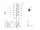
- FIG. 2 is a schematic diagram showing an optical path configuration in an example of a conventional image display device using a light guide disclosed in Patent Documents 1 to 3 and the like.
- x, y, and z axes orthogonal to each other are defined as shown in the figure.
- the image display device includes a light source unit 1, a display element 2, a collimating optical system 3, and a light guide 10.
- the display element 2 is a transmissive liquid crystal display element
- the light source unit 1 is a backlight light source for a so-called transmissive liquid crystal display element.
- Image light light including an image formed on the display surface of the display element 2 as information is emitted from the display element 2.
- the collimating optical system 3 introduces the image light emitted from each point (pixel) on the display surface of the display element 2 into the light guide 10 as a substantially parallel light flux. Therefore, the light introduced from the collimating optical system 3 to the light guide 10 includes information on different parts of an image formed on the display surface of the display element 2 and the parallel light flux entering the light guide 10 at different angles. Is a set of
- the light guide 10 is opposed to the first surface 11a and the second surface 11b, which are both parallel to the yz plane and are spaced apart in the x-axis direction, and are opposed to each other, being parallel to the xy plane and separated in the z-axis direction.
- a transparent substrate 11 having a flat cubic shape having a third surface and a fourth surface (not shown).
- One incident-side reflection surface 12 and a plurality (five in this example) of emission-side reflection surfaces 13a to 13e are formed inside a substrate 11.
- the incident-side reflecting surface 12 is perpendicular to the third and fourth surfaces of the substrate 11 and is inclined with respect to the first surface 11a and the second surface 11b.
- the plurality of exit-side reflecting surfaces 13a to 13c are also perpendicular to the third surface and the fourth surface, are inclined with respect to the first surface 11a and the second surface 11b, and are parallel to each other.
- the incident-side reflecting surface 12 is a reflecting surface of a mirror or the like
- the emitting-side reflecting surfaces 13a to 13e are partially reflecting surfaces, that is, a beam splitter or a half that reflects part of the irradiated light and transmits the rest. It is a mirror.
- image light including information on different portions of an image formed on the display surface of the display element 2 enters the substrate 11 of the light guide 10 at different angles as parallel light beams, and is reflected by the incident-side reflection surface 12.
- the luminous flux of this image light propagates inside the substrate 11 while being repeatedly reflected on the first surface 11a and the second surface 11b of the substrate 11, and is transmitted to the emission-side reflection surface 13a located closest to the incidence-side reflection surface 12.
- the emission-side reflection surface 13a reflects a part of the image light that has arrived and transmits the rest according to the transmittance.
- the transmitted image light reaches the next exit-side reflecting surface 13b, and a part of the light is reflected, and the rest is transmitted.
- the image formed on the display surface of the display element 2 is displayed in front of the user as a virtual image. Further, since the substrate 11 of the light guide 10 is transparent and the emission-side reflecting surfaces 13a to 13e are partially reflecting surfaces, the user can visually recognize the scenery ahead through the substrate 11 of the light guide 10. That is, this image display device is a see-through type image display device, and can superimpose and display an arbitrary virtual image on a landscape.
- the above-described see-through type image display apparatus superimposes an image (virtual image) based on an external background light (hereinafter, sometimes referred to as a “background image”) and an image based on image light emitted from an image emitting unit (virtual image).
- a background image an external background light
- an image based on image light emitted from an image emitting unit virtual image.
- the visibility of the image by the image light is reduced.
- a see-through type image display device using a light guide since the light path when the image light passes through the light guide substrate is long and the light intensity is attenuated, the brightness of the image due to the image light tends to be low. is there. Therefore, there is a problem that the visibility of an image is significantly reduced by the image light when the wavelength of the image light is close to the wavelength of the background light, as compared with an image display device that does not use a light guide.
- Patent Document 4 discloses a method of improving the visibility of a virtual image superimposed on a background image in a see-through type image display device that does not use a light guide.
- a light source unit that captures a background image with a camera, analyzes the background image, and emits light that forms a virtual image so that the contrast with the background image is good.
- control is performed such as displaying a virtual image in a different color from the portion where the virtual image overlaps in the background image.
- a see-through type image display device using a light guide cannot employ the method described in Patent Document 4 for the following reasons.
- see-through image display devices using light guides are often used for helmet mount displays for aircraft and helicopter operators, but in such applications, light-emitting devices are usually used to increase the angle of view.
- a glass material colored with a high refractive index is used as a material for the guide. Therefore, for example, the color of light output from an image forming unit such as an LCD often differs from the color of a display image observed by a user, and a display color that provides sufficient contrast with a background image is often used. Even if it is selected, the virtual image actually displayed in front of the user's eyes does not always have a sufficiently high contrast with respect to the background image.
- the present invention has been made to solve the above problems, and an object of the present invention is to superimpose and display an image based on background light in front of a user in a see-through type image display device using a light guide.
- the purpose is to improve the visibility of the virtual image.
- the present invention has been made to solve the above-described problems, an image forming unit that emits image light including two-dimensional image information, a transparent substrate, an incident unit that guides the image light inside the substrate, And a light guide having an emission unit for emitting image light that has been guided inside the substrate by the incidence unit and has traveled inside the substrate to the outside of the substrate, and a light guide having an emission unit.
- An image display device that displays a virtual image formed in front of a user's eyes by image light emitted from the emission unit, superimposed on a background image seen by the user through the light guide,
- a background information acquisition unit that recognizes a color of a background light forming at least a part of the background image or a wavelength region corresponding to the color, The background visible to the user based on the color of the background light obtained by the background information obtaining unit or information on the wavelength region corresponding to the color, and at least the wavelength transmission characteristic information of the optical system including the light guide.
- a display control unit that controls the image forming unit to change the color or wavelength of image light corresponding to at least a part of the image emitted from the image forming unit so that the visibility of the virtual image with respect to the image is improved.
- a reflection surface such as a mirror provided inside or on the surface of the substrate, or a holographic element such as a volume holographic diffraction grating is used. be able to.
- a partial reflection surface such as a plurality of beam splitters and half mirrors provided inside the substrate, a reflection surface such as a mirror provided inside or on the substrate, or a holographic element is used. Can be.
- the light guide which is typically in the form of a flat plate, is arranged in front of the user (observer) so as to face the user.
- a plurality of light guides may be combined.
- the light guide at the last stage is arranged to face the user.
- a background image such as a landscape, is displayed in front of the user with background light transmitted through the light guide substrate in the thickness direction of the light guide disposed facing the user.
- the image light whose optical path is bent so as to be guided inside the substrate from the emission section toward the user's eye, and in front of the user's eyes, a virtual image such as character information or graphic information is superimposed on the background image. Is displayed.
- the background information acquisition unit recognizes the color of the background light forming at least a part of the background image, or the wavelength corresponding to the color, which enters the light guide substrate from the surface opposite to the surface facing the user.
- "at least a part of the background image” is around the portion where the virtual image is superimposed when viewed from the user, that is, when the background image on which the virtual image is superimposed is in contact with the periphery of the virtual image. It is a background image of a part. Therefore, for example, when the virtual image is superimposed only on the lower part of the background image seen by the user, it is sufficient to recognize the color or wavelength of the background light forming the lower background image.
- the background light forming at least a part of the background image may include light of a plurality of colors, in which case, one of the main colors among the plurality of colors or the wavelength corresponding thereto. May be recognized, or the color of the background light corresponding to each fine area on the background image or the wavelength corresponding thereto may be recognized.
- the background information acquisition unit may acquire the approximate wavelength spectrum (color information) of the background light in a predetermined range in real time.
- a unitized or IC-based color A sensor color discrimination sensor
- Such a color sensor is, for example, a two-dimensionally arranged mosaic arrangement of minute light receiving portions having sensitivity to the three primary colors of red, green and blue.
- the display control unit typically performs, for example, a predetermined calculation based on acquired color or wavelength information of background light, wavelength transmission characteristic information of an optical system including a light guide, and information on human visibility.
- the virtual image displayed in front of the user's eyes through the light guide is emitted from the image forming unit or the color or wavelength of the image light so that high visibility is obtained for the background image.
- Wavelength correction information for correcting the wavelength of the image light is obtained.
- the image data itself is corrected so as to change at least a part of the color of the image information to be displayed as a virtual image.
- the image forming unit is controlled so as to change the color of a part of the irradiation light applied to the display element to form the image light.
- the display control unit selects the color of the image light in which the contrast of the virtual image with respect to the background image seen by the user is high, or adjusts the color of the image light so that the contrast is high, so that the virtual image Visibility can be improved. More specifically, the display control unit is configured to determine the color of the image light based on a difference in one or more color attributes of hue, saturation, or brightness between the background image seen by the user and the virtual image overlapping the background image. Is selected or adjusted, the contrast of the virtual image with respect to the background image can be increased.
- the change in color depending on the wavelength transmission characteristics of the light guide from the time when the image light is introduced into the light guide to the time when the light is emitted from the emission part and reaches the user's eyes is considered. Therefore, the color of the virtual image superimposed on the background image seen through the light guide is set to a color with high visibility with respect to the background image.
- the color of the virtual image superimposed on the background image seen through the light guide is also one color. Instead, a plurality of colors with high visibility can be set for a partial background image where the virtual images overlap.
- the visibility of a virtual image is higher than that of a background image.
- the visibility of information having low importance may be intentionally reduced. is there.
- the image forming unit may be controlled so that the color or wavelength region of the image light emitted from the light guide is close to the color or wavelength region of the background light.
- the image display device of the present invention regardless of the color of the background image displayed in front of the user's eyes, by improving the visibility of the virtual image displayed superimposed on the background image, it can. As a result, it is possible to reduce oversight or oversight by the user of character information, graphic information, or the like displayed as a virtual image.
- FIG. 1 is a schematic configuration diagram of an image display device according to an embodiment of the present invention.
- FIG. 2 is a schematic configuration diagram of an optical system in an example of a conventional image display device.
- FIG. 1 is a schematic configuration diagram of the image display device of the present embodiment.
- the image display device of the present embodiment includes a light source unit 1, a display element 2, a collimating optical system 3, and a light guide 10, similarly to the conventional image display device shown in FIG.
- These components can be the same as those in the conventional device, but are not limited thereto.
- a transmissive liquid crystal display element a reflective liquid crystal display element, an organic EL display, a DMD (digital macro mirror device), a MEMS mirror, a projector, or the like can be used as the display element 2.
- the light source unit 1 illuminates the liquid crystal display element or DMD from the front side.
- a self-luminous display element such as an organic EL display
- the light source unit 1 is built in the display element 2.
- a MEMS mirror whose angle is scanned is used as the display element 2
- a laser light source that irradiates a thin laser beam toward the MEMS mirror is used as the light source unit 1
- the collimating optical system 3 is omitted or Alternatively, the collimating optical system 3 may be used for the purpose of finely adjusting the parallel light.
- the light source unit 1 can be regarded as a projector and the display element 2 can be regarded as a projector screen.
- the light guide 10 has a first surface 11a and a second surface 11b, which are both parallel to the yz plane and are spaced apart in the x-axis direction, and both are parallel to the xy plane and are spaced apart in the z-axis direction.
- a flat cubic substrate 11 having a third surface and a fourth surface (not shown) facing each other is provided.
- the substrate 11 is typically a transparent body such as quartz glass or glass.
- One incident side reflection surface 12 and a plurality of (five in this example) emission side reflection surfaces 13a to 13e are formed inside the substrate 11.
- the incident side reflection surface 12 is perpendicular to the third surface and the fourth surface, and is inclined at a predetermined angle with respect to the first surface 11a and the second surface 11b.
- the plurality of emission-side reflection surfaces 13a to 13e are perpendicular to the third surface and the fourth surface, respectively, and are inclined at a predetermined angle with respect to the first surface 11a and the second surface 11b.
- the incident-side reflecting surface 12 is a reflecting surface formed by a mirror or the like, and the emitting-side reflecting surfaces 13a to 13e are partial reflecting surfaces having predetermined reflectance characteristics (transmittance characteristics).
- the image display device of the present embodiment further includes functional blocks such as a color identification sensor 20, an image information providing unit 21, a display control unit 22 including a color tone correction processing unit 23, and a storage unit 24.
- the storage unit 24 stores information on general human visibility, the wavelength transmission characteristics of an optical system for displaying a virtual image centered on the light guide 10, the wavelength characteristics of illumination light emitted from the light source unit 1, and the like. Is stored.
- the display element 2 receives the illumination light from the light source unit 1 and forms image light.
- the illumination light at this time is light in a visible region, for example, white light.
- Image light emitted from the display screen of the display element 2 is converted into substantially parallel light by the collimating optical system 3 and is introduced into the substrate 11 of the light guide 10 through the first surface 11a.
- the image light introduced from the collimating optical system 3 to the light guide 10 includes information on different portions of a two-dimensional image formed on the display surface of the display element 2 and enters the light guide 10 at different angles. Is a set of parallel light fluxes.
- the image light After being reflected by the incident-side reflecting surface 12, the image light travels inside the substrate 11 while being reflected by the first surface 11a and the second surface 11b one or more times, and reaches the emitting-side reflecting surface 13a.
- the exit-side reflecting surface 13a reflects a part of the arriving light beam and transmits the rest.
- the other emission-side reflection surfaces 13b to 13e As a result, the light beam that has propagated inside the substrate 11 of the light guide 10 is reflected little by little on each of the plurality of emission-side reflection surfaces 13a to 13e, and is emitted to the outside through the second surface 11b of the substrate 11. Reaches the eye E of the person. That is, the image formed on the display surface of the display element 2 is enlarged and displayed as a virtual image in front of the user's eye E.
- background light including image information such as external scenery enters the substrate 11 from the first surface 11a of the substrate 11 of the light guide 10, passes through the substrate 11 in a substantially thickness direction thereof, and The light exits from the surface 11b and reaches the user's eye E.
- a background image based on the background light is displayed in front of the user.
- the color identification sensor 20 obtains, in real time, rough wavelength distribution characteristics of background light incident on the light guide 10, that is, color information. At this time, it is preferable to obtain the wavelength distribution characteristic of the background light corresponding to a predetermined range of the background image around the portion where the virtual image is superimposed when viewed from the user. For example, when the image display device is mounted on a helmet mount display used by an aircraft operator, the background image is often a blue sky or a white or gray cloud in the daytime. In the nighttime, the background image is often a black sky. In such a case, a wavelength distribution characteristic centering on a color such as blue, white, gray, or black can be obtained.
- the color identification sensor 20 includes, for example, light detection sensors of three colors, red (R), green (G), and blue (B), and a signal processing unit that processes detection outputs of these sensors to calculate color information. Combinations can be used. In this case, the ratio of each of the R, G, and B color components can be obtained as information on the color of the incident light, and the actual color can be estimated from the ratio.
- a unit that can acquire light intensity for each wavelength by combining a spectral element such as a prism or a grating with a photodiode array may be used. In this case, a wavelength spectrum can be obtained as information corresponding to the color of the target light.
- the image information providing unit 21 inputs image data to be displayed as a virtual image to the display control unit 22, and the display control unit 22 controls the light source unit so that an image based on the image data is formed on the display surface of the display element 2. 1 and the display element 2 are driven.
- an image based on image data input from the image information providing unit 21 is formed on the display surface of the display element 2 as it is, that is, without changing or adjusting the color.
- the color tone correction processing unit 23 is input from the color identification sensor 20 with the visibility information, the optical system wavelength transmission characteristic information, and the light source wavelength characteristic information read from the storage unit 24. Based on the color information of the background light at that time, the image data is corrected by executing an arithmetic process according to a predetermined algorithm.
- the color tone correction processing unit 23 corrects the color of the image data so that the virtual image displayed in front of the user's eyes has as high a visibility as possible with respect to the background image. Specifically, for example, the following may be performed.
- the reason why the opposite color is obtained is that the contrast is high because the color has the largest difference in hue, which is one of the color attributes.
- the opposite color is a color used for displaying a virtual image, but the image light introduced into the substrate 11 of the light guide 10 has a wavelength distribution, that is, a color due to its wavelength transmission characteristic while passing through the inside of the substrate 11. Change. Although the background light also passes through the inside of the substrate 11, its optical path length is much shorter than that of the image light, so that the change in the wavelength characteristic of the background light, that is, the change in color is ignored.
- the light is introduced into the light guide 10 so that the color of the image light after the change in the wavelength distribution due to the optical system wavelength transmission characteristics, that is, the color of the image light emitted from the substrate 11 of the light guide 10 is the opposite color.
- the wavelength distribution of the image light, that is, the color is obtained by back calculation.
- the contrast is increased from the viewpoint of other color attributes, such as saturation and brightness, or from the viewpoint of a combination of a plurality of color attributes.
- a different color may be obtained. That is, the color may be adjusted so as to increase the visibility by reflecting the human visibility characteristics.
- a color that is not appropriate for display may be selected. For example, when it is desired to always provide a display that gives a warning to the user in red, it is necessary to avoid red or a color close to red in a normal display. In such a case, a color having the highest contrast may be selected from a plurality of predetermined colors. That is, the color of the image light for displaying the virtual image may be selected in consideration of factors other than the actual visibility.
- the color of the image formed on the display screen of the display element 2 changes depending on the color of the background light, and accordingly, the color of the virtual image displayed in front of the user over the background image changes.
- the display color of the virtual image is, for example, the opposite color of the main color of the background image portion of the background image, so that the user can clearly recognize the virtual image.
- the display control unit 22 may change the color of the illumination light emitted from the light source 1 instead of changing the color of the image data.
- the color of the image light introduced from the collimating optical system 3 to the substrate 11 of the light guide 10 may be appropriately changed according to the color of the background light.
- the virtual image displayed in front of the user is not corrected by correcting the color of the image data so that the virtual image displayed in front of the user has the highest visibility with respect to the background image. It is also possible to correct the color of the image data so that the visibility of the image data becomes low. This is effective when, for example, character information or the like is displayed as a virtual image, but its importance is low, and it is rather desired not to hinder the visual recognition of the background image.
- each unit can be appropriately changed.
- a hologram surface such as a reflection-type volume hologram grating may be used as an incident portion for guiding image light into the substrate 11 of the light guide 10 instead of the reflection surface formed inside the substrate 11.
- the image light is reflected on the non-parallel surface (the interface between the substrate 10 and the outside world).
- the reflection surface may be used as an incident portion.
- the third and fourth surfaces of the substrate 11 of the light guide 10 are parallel to each other, but the third and fourth surfaces need not be parallel to the xy plane. That is, the first surface 11a, the second surface 11b, the incident-side reflecting surface 12, and the emitting-side reflecting surfaces 13a to 13e need not be perpendicular to the third surface and the fourth surface.
- the shapes of the third surface and the fourth surface can be arbitrarily determined.
Landscapes
- Physics & Mathematics (AREA)
- General Physics & Mathematics (AREA)
- Optics & Photonics (AREA)
Abstract
La présente invention concerne un capteur d'identification de couleur (20) qui identifie la couleur de la lumière de fond faisant partie d'une image d'arrière-plan qui atteint les yeux d'un utilisateur à travers un guide de lumière (10). Une unité de traitement de correction de ton de couleur (23) trouve une couleur de lumière d'image, une image virtuelle affichée devant les yeux de l'utilisateur aura ainsi une visibilité élevée par rapport à l'image d'arrière-plan, sur la base d'informations concernant les capacités de reconnaissance visible chez l'être humain, d'informations de caractéristique de transmission de longueur d'onde d'un système optique tel que le guide de lumière (10), et des informations de caractéristique de longueur d'onde de la lumière provenant d'une unité de source de lumière (1) qui sont lues à partir d'une unité de mémoire (24), ainsi que des informations de couleur de la lumière de fond qui a été identifiée. En fonction de son résultat, une unité de commande d'affichage (22) corrige les données d'image et commande ensuite l'unité de source de lumière (1) et un élément d'affichage (2). Ceci permet d'afficher, devant les yeux de l'utilisateur, une image virtuelle qui est distinctement visible par rapport à une image d'arrière-plan même si un substrat (11) du guide de lumière (10) a été coloré.
Priority Applications (1)
| Application Number | Priority Date | Filing Date | Title |
|---|---|---|---|
| PCT/JP2018/029519 WO2020031247A1 (fr) | 2018-08-07 | 2018-08-07 | Dispositif d'affichage d'image |
Applications Claiming Priority (1)
| Application Number | Priority Date | Filing Date | Title |
|---|---|---|---|
| PCT/JP2018/029519 WO2020031247A1 (fr) | 2018-08-07 | 2018-08-07 | Dispositif d'affichage d'image |
Publications (1)
| Publication Number | Publication Date |
|---|---|
| WO2020031247A1 true WO2020031247A1 (fr) | 2020-02-13 |
Family
ID=69413424
Family Applications (1)
| Application Number | Title | Priority Date | Filing Date |
|---|---|---|---|
| PCT/JP2018/029519 Ceased WO2020031247A1 (fr) | 2018-08-07 | 2018-08-07 | Dispositif d'affichage d'image |
Country Status (1)
| Country | Link |
|---|---|
| WO (1) | WO2020031247A1 (fr) |
Cited By (1)
| Publication number | Priority date | Publication date | Assignee | Title |
|---|---|---|---|---|
| JP2024542382A (ja) * | 2021-10-29 | 2024-11-15 | 華為技術有限公司 | 光学表示装置、表示システム、ビークル、および色調整方法 |
Citations (5)
| Publication number | Priority date | Publication date | Assignee | Title |
|---|---|---|---|---|
| JP2005138801A (ja) * | 2003-11-10 | 2005-06-02 | Calsonic Kansei Corp | ヘッドアップディスプレイ装置 |
| WO2010131400A1 (fr) * | 2009-05-14 | 2010-11-18 | 株式会社ナナオ | Appareil d'affichage d'image stéréoscopique |
| JP2012058404A (ja) * | 2010-09-07 | 2012-03-22 | Shimadzu Corp | 光学部品及びそれを用いた表示装置 |
| JP2016101771A (ja) * | 2014-11-27 | 2016-06-02 | クラリオン株式会社 | 車両用ヘッドアップディスプレイ装置 |
| WO2017130683A1 (fr) * | 2016-01-29 | 2017-08-03 | 富士フイルム株式会社 | Demi miroir et miroir avec fonction d'affichage d'image |
-
2018
- 2018-08-07 WO PCT/JP2018/029519 patent/WO2020031247A1/fr not_active Ceased
Patent Citations (5)
| Publication number | Priority date | Publication date | Assignee | Title |
|---|---|---|---|---|
| JP2005138801A (ja) * | 2003-11-10 | 2005-06-02 | Calsonic Kansei Corp | ヘッドアップディスプレイ装置 |
| WO2010131400A1 (fr) * | 2009-05-14 | 2010-11-18 | 株式会社ナナオ | Appareil d'affichage d'image stéréoscopique |
| JP2012058404A (ja) * | 2010-09-07 | 2012-03-22 | Shimadzu Corp | 光学部品及びそれを用いた表示装置 |
| JP2016101771A (ja) * | 2014-11-27 | 2016-06-02 | クラリオン株式会社 | 車両用ヘッドアップディスプレイ装置 |
| WO2017130683A1 (fr) * | 2016-01-29 | 2017-08-03 | 富士フイルム株式会社 | Demi miroir et miroir avec fonction d'affichage d'image |
Cited By (2)
| Publication number | Priority date | Publication date | Assignee | Title |
|---|---|---|---|---|
| JP2024542382A (ja) * | 2021-10-29 | 2024-11-15 | 華為技術有限公司 | 光学表示装置、表示システム、ビークル、および色調整方法 |
| JP7795623B2 (ja) | 2021-10-29 | 2026-01-07 | 深▲ジェン▼引望智能技術有限公司 | 光学表示装置、表示システム、ビークル、および色調整方法 |
Similar Documents
| Publication | Publication Date | Title |
|---|---|---|
| CN104903774B (zh) | 用于近眼显示器的光组合器 | |
| JP5732808B2 (ja) | 虚像表示装置 | |
| US9298001B2 (en) | Optical configurations for head worn computing | |
| US8681143B2 (en) | Display apparatus, mobile object and control apparatus | |
| US8035872B2 (en) | Image combiner and image display device | |
| US20210033774A1 (en) | Image display device | |
| US20130234915A1 (en) | Virtual image display apparatus | |
| WO2012118125A1 (fr) | Dispositif d'affichage à réflexion | |
| JP2015194654A (ja) | 光学デバイス、画像投影装置及び電子機器 | |
| US20260118677A1 (en) | Systems, devices, and methods for inputting light from a scanning projector into a waveguide | |
| US20250277978A1 (en) | Projection optical system and glasses-type terminal | |
| JP2015194550A (ja) | 光学デバイス、画像投影装置及び電子機器 | |
| JPWO2018043254A1 (ja) | 映像表示装置と光学シースルーディスプレイ | |
| KR101995710B1 (ko) | 도파관을 이용한 디스플레이장치 및 그것을 위한 영상표시방법 | |
| US20250067981A1 (en) | Binocular display system for an eyewear display | |
| WO2020031247A1 (fr) | Dispositif d'affichage d'image | |
| US12313855B2 (en) | Systems and methods to separate scanning mirror input and output light | |
| JP2017058388A (ja) | 虚像表示装置 | |
| JP2015118223A (ja) | ヘッドアップディスプレイ装置 | |
| US20250244586A1 (en) | Projection optical system and glasses-type terminal | |
| WO2019155567A1 (fr) | Guide de lumière et dispositif d'affichage d'image | |
| US20250377541A1 (en) | Eyewear display alignment and intensity monitoring using converted light | |
| JP2015096982A (ja) | 虚像表示装置 | |
| WO2019077975A1 (fr) | Dispositif d'affichage vidéo et affichage optique transparent | |
| JPWO2019008646A1 (ja) | 頭部装着型表示装置 |
Legal Events
| Date | Code | Title | Description |
|---|---|---|---|
| 121 | Ep: the epo has been informed by wipo that ep was designated in this application |
Ref document number: 18929756 Country of ref document: EP Kind code of ref document: A1 |
|
| NENP | Non-entry into the national phase |
Ref country code: DE |
|
| 122 | Ep: pct application non-entry in european phase |
Ref document number: 18929756 Country of ref document: EP Kind code of ref document: A1 |
|
| NENP | Non-entry into the national phase |
Ref country code: JP |