WO2020031383A1 - Lacet tricoté - Google Patents
Lacet tricoté Download PDFInfo
- Publication number
- WO2020031383A1 WO2020031383A1 PCT/JP2018/030138 JP2018030138W WO2020031383A1 WO 2020031383 A1 WO2020031383 A1 WO 2020031383A1 JP 2018030138 W JP2018030138 W JP 2018030138W WO 2020031383 A1 WO2020031383 A1 WO 2020031383A1
- Authority
- WO
- WIPO (PCT)
- Prior art keywords
- yarn
- loop
- chain knitting
- chain
- insertion yarn
- Prior art date
- Legal status (The legal status is an assumption and is not a legal conclusion. Google has not performed a legal analysis and makes no representation as to the accuracy of the status listed.)
- Ceased
Links
Images

Classifications
-
- D—TEXTILES; PAPER
- D04—BRAIDING; LACE-MAKING; KNITTING; TRIMMINGS; NON-WOVEN FABRICS
- D04B—KNITTING
- D04B21/00—Warp knitting processes for the production of fabrics or articles not dependent on the use of particular machines; Fabrics or articles defined by such processes
- D04B21/10—Open-work fabrics
Definitions
- the present invention relates to a lace knitted fabric that can be suitably used as a fabric or ruffle for women's underwear having elasticity.
- Patent Documents 1 and 2 The invention relating to the lace knitted fabric of the prior art is described in Patent Documents 1 and 2, for example.
- the lace knitted fabric is composed of a covering yarn in which a covering yarn is wound around a core yarn, and a chain knitting yarn forming a chain knitting structure forming one wale;
- a technique has been proposed in which an insertion yarn knitted in a course direction as an elastic yarn is bonded to a tissue by heat fusion at a contact portion to prevent fraying at a cut portion.
- the chain knitting yarn and the insertion yarn are adhered at the contact portion to prevent fraying and the like.
- the chain knitting yarn wound around the insertion yarn may be pulled by the insertion yarn and cut.
- the cut portion of the lace knitted fabric is pulled with a strong force in the direction in which the wale extends, the inserted thread may come off from the adhesive portion and the cut end may be torn.
- an object of the present invention is to provide a lace knitted fabric having a good texture, in which breakage of chain knitting yarns during knitting is suppressed, and cut ends are not torn.
- the present invention is a lace knitted fabric in which a chain stitch structure of a chain knitting yarn in which a plurality of loop-shaped portions continue in a course direction is formed in a plurality of rows in a wale direction, A first insertion yarn made of an elastic yarn having elasticity that elastically expands and contracts and is inserted into each of the loop-shaped portions in the course direction and knitted into a chain knitting structure; A second insertion yarn made of an elastic yarn having elasticity that elastically expands and contracts, and a part of the plurality of loop-shaped portions is inserted in the course direction and knitted into a chain stitch structure; A third insertion yarn made of an elastic yarn having elasticity that elastically expands and contracts, A parallel running portion that is inserted in the course direction through the loop-shaped portion of the chain stitch and knitted alongside the second insertion yarn; A third insertion yarn having, from a predetermined chain stitch structure, a loop portion of the chain stitch structure adjacent to one side in the wale direction and a crossover portion knitted into a loop
- the first insertion yarn is adhered to the chain knitting yarn at a position in contact with each loop-shaped portion of the chain knitting yarn constituting each of the plurality of chain knitting structures
- the second insertion yarn is adhered to the chain knitting yarn at a position in contact with each loop-shaped portion of the chain knitting yarn constituting each of the plurality of chain knitting structures
- the third insertion yarn is a lace knitted fabric characterized in that the third insertion yarn is adhered to the chain knitting yarn at a position in contact with each loop-shaped portion of the chain knitting yarn constituting each of the plurality of chain knitting structures.
- the chain knitting yarn, the second insertion yarn and the third insertion yarn have a core yarn composed of a single fiber yarn made of a heat-fusible synthetic resin, and a melting temperature lower than the core yarn. And a covering yarn made of a long fiber yarn made of a high heat-fusible synthetic resin.
- the loop-shaped portion has a first loop-shaped portion formed by a needle loop and a second loop-shaped portion formed by a sinker loop,
- the laterally extending portion is the second loop-shaped portion.
- the second insertion yarn and the third insertion yarn are formed of the same material and have the same thickness.
- the laterally extending portions of the chain knitting yarns constituting each chain stitch structure are adjacent to one side in the wale direction in a state in which they extend laterally from each chain stitch structure to the chain stitch structure adjacent to one side in the wale direction. Because of the configuration of being hooked on the second insertion yarn and the parallel insertion portion of the third insertion yarn knitted in the chain knitting structure, the chain knitting yarn of the laterally extending portion is separated from the second insertion yarn and the third insertion yarn. It is in a state of losing the tensile force it receives.
- the configuration of the laterally extending portion can prevent the fused portion of the second insertion yarn and the third insertion yarn from peeling or coming off. Further, since the tensile force applied to the chain knitting yarn in the laterally stretched portion is reduced, a lace knitted fabric excellent in elasticity can be realized. Further, since the laterally extending portion is hooked on the two insertion yarns of the second insertion yarn and the third insertion yarn, the laterally extending portion can be surely laterally extended to the chain knitting structure adjacent to one side in the wale direction. it can.
- the core yarn Does not come into contact with the skin, but the bulky coated yarn comes into contact with the skin.
- the laterally extending portion is the second loop portion formed by the sinker loop and not the first loop portion formed by the needle loop, the stitches of the lace knitted fabric are deformed. Can be suppressed.
- the second insertion yarn and the third insertion yarn are formed of the same material and have the same thickness, so that the second insertion yarn and the third insertion yarn are connected to each other. It can be easily fused to a chain knitting yarn at a specific temperature.
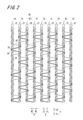
- 1 is a knitting structure diagram showing a part of a lace knitted fabric 20 in which a chain knitting yarn 21 according to an embodiment of the present invention is laterally extended.
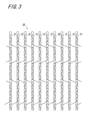
- 1 is a chain knitting structure diagram showing a lace knitted fabric 20 by omitting yarns other than a chain knitting yarn 21, a first insertion yarn 22, a second insertion yarn 23, and a third insertion yarn 24.
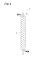
- It is a run stop organization diagram which shows the lace knitted fabric 20 by omitting the yarns other than the chain knitting yarn 21.
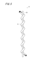
- It is a front view showing a part of chain knitting yarn 21 before knitting.
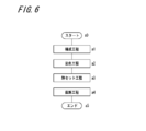
- FIG. 3 is a front view showing a part of a chain knitting yarn 21 knitting a lace knitted fabric 20. It is a flowchart which shows the manufacturing process of the lace knitted fabric 20 of this embodiment.
- FIG. 1 is a knitting structure diagram showing a part of a lace knitted fabric 20 according to an embodiment of the present invention, in which a chain stitch yarn 21 constituting a chain stitch structure 19a is adjacent to the chain stitch structure 19a in one wale direction. This shows a state where the chain stitch structure 19b extends laterally.
- FIG. 2 is a knitting structure diagram of a chain knitting structure 19 showing the lace knitted fabric 20 by omitting yarns other than the chain knitting yarn 21, the second insertion yarn 23, and the third insertion yarn 24.
- FIG. 1 is a knitting structure diagram showing a part of a lace knitted fabric 20 according to an embodiment of the present invention, in which a chain stitch yarn 21 constituting a chain stitch structure 19a is adjacent to the chain stitch structure 19a in one wale direction. This shows a state where the chain stitch structure 19b extends laterally.
- FIG. 2 is a knitting structure diagram of a chain knitting structure 19 showing the lace knitted fabric 20 by omitting yarns other than the
- FIG. 3 is a knitting structure diagram of a run stop structure 28 showing the lace knitted fabric 20 by omitting yarns other than the chain knitting yarn 21.
- 1 to 3 schematically show the knitting structure for easy understanding, and the actual knitting structure of the lace knitted fabric 20 includes the first loop-shaped portion 25 and the second loop-shaped portion.
- the radius of curvature of the portion 26 is small, and the chain knitting yarn 21, the first insertion yarn 22, the second insertion yarn 23, and the third insertion yarn 24 are in a state of being extremely close to or in contact with each other.
- FIG. 2 is shown by the solid line which omitted thickness of the chain knitting yarn 21, the 2nd insertion yarn 23, and the 3rd insertion yarn 24, and FIG. This is indicated by a solid line with the thickness omitted.
- the knitted fabric knitted by the chain knitting yarn 21, the first insertion yarn 22, the second insertion yarn 23, and the third insertion yarn 24 is referred to as a precursor knitted fabric.
- the lace knitted fabric 20 is obtained by heating a precursor knitted fabric. Further, products manufactured using the lace knitted fabric 20 are referred to as knitted lace products.
- the lace knitted fabric 20 of the present embodiment is a warp knitted fabric, a raschel knitted raschel knitted fabric, and a stretch knitted fabric having elasticity.
- the lace knitted fabric 20 is knitted by a yarn including a chain knitting yarn 21, a first insertion yarn 22, a second insertion yarn 23, and a third insertion yarn 24.
- the lace knitted fabric 20 includes a chain knitting yarn 21 in which a plurality of first loop-shaped portions 25 and second loop-shaped portions 26 are connected in a course direction to form a chain knitted structure 19 of Russell knitting, A first insertion yarn 22 that is knitted in the chain knitting structure 19 in the course direction C to give the chain knitting structure 19 elasticity in the course direction C;
- Each second loop-shaped portion 26 of the chain knitting yarn 21 formed of an elastic yarn having elasticity to form one chain knitting structure 19a and the chain knitting yarn 21 forming the chain knitting structure 19b adjacent in the wale direction W
- a second insertion yarn 23 and a third insertion yarn 24 that give each chain stitch structure 19 elasticity in the wale direction W.
- the chain knitting yarn 21 may be referred to as a warp or a ground knitting yarn. Further, the first insertion yarn 22 is also referred to as a stretch yarn, and the second insertion yarn 23 and the third insertion yarn 24 are also referred to as weft yarns.
- the chain knitting yarn 21 and the first insertion yarn 22 are bonded to each other at the plurality of first contact portions 50 by utilizing their mutual heat-fusibility.
- the chain knitting yarn 21 and the first insertion yarn 22 are bonded at almost all the first contact portions 50.
- a plurality of second contact portions 55 of the chain knitting yarn 21 and the second insertion yarn 23 are bonded to each other by utilizing their mutual heat-fusibility.
- Almost all of the third contact portions 56 are bonded to the chain knitting yarn 21 and the third insertion yarn 24.
- the chain knitting yarn 21 is formed into a first loop-shaped portion 25 and a second loop-shaped portion 26 by chain knitting.
- the first loop-shaped portions 25 and the second loop-shaped portions 26 are formed alternately and continuously in a plurality of stages in the course direction C.
- the first loop-shaped portion 25 may be called a needle loop
- the second loop-shaped portion 26 may be called a sinker loop.
- the chain knit structure 19 is formed by the first loop-shaped portions 25 and the second loop-shaped portions 26 being alternately connected and extending in the course direction C.
- a plurality of chain stitch structures 19 are formed side by side in the wale direction W and are connected to each other to form a lace knitted fabric 20, in other words, a chain stitch structure.
- the chain knitting yarn 21 forms not only the chain knitting structure 19 but also a run-stopping structure 28 for preventing transmission lines shown in FIG. 3 or a tulle structure composed of a turtle-shaped net as a ground structure. You can also.
- a portion where the chain knitting yarn 21 extends laterally is referred to as a laterally extending portion 42.
- Each of the first loop-shaped portions 25 is formed substantially in a U-shape, and is arranged substantially side by side in a predetermined course direction C and a wale direction W orthogonal to the course direction C. Further, each first loop-shaped portion 25 opens to the front stage C1 in the course direction, which is one in the course direction C.
- the first loop portions 25 are arranged in a line in the wale direction W to form a course, and the first loop portions 25 are arranged in a line in the course direction C to form a wale.
- the second loop portion 26 connects the first loop portions 25 arranged in the course direction C.
- the second loop-shaped portion 26 of interest has one end connected to the end of the first loop-shaped portion 25 at the same level as the second loop-shaped portion 26.
- the second loop-like portion 26 extends from one end to the other end by inserting the first loop-like portion 25 of the first stage C1 in the course direction C1 of the second loop-like portion 26 from one side to the other side in the course direction.
- the first loop-shaped portion 25 at the same level as the second loop-shaped portion 26 is inserted from the other side to one side, and extends to the subsequent stage C2 in the course direction. Of the first loop-shaped portion 25.
- first loop-shaped portion 25 and the second loop-shaped portion 26 are connected in a chain, and a wale extending in the course direction C is formed.
- Each insertion yarn such as the first insertion yarn 22, the second insertion yarn 23, and the third insertion yarn 24 is knitted between the first loop-shaped portion 25 and the second loop-shaped portion 26 to be knitted into wale. It is.
- the course direction C is the warp direction of the knitted fabric and means the lace knitting direction.
- the wale direction W is a lateral direction of the knitted fabric and means a direction intersecting the lace knitting direction.
- the plurality of first loop-shaped portions 25 are arranged side by side in the course direction C and the wale direction W.
- the plurality of first loop portions 25 arranged in the course direction C and the wale direction W are arranged substantially in contact with a predetermined virtual plane.
- the knitting yarns knitted in the chain knitting structure 19, such as the first insertion yarn 22, the second insertion yarn 23, and the third insertion yarn 24, are arranged on one side with respect to the virtual plane.
- a direction in which the first insertion yarn 22, the second insertion yarn 23, and the third insertion yarn 24 are arranged with respect to the virtual plane extending along the first loop-shaped portion 25 is referred to as a front direction Z1, and the first insertion yarn
- the direction in which the virtual plane is arranged with respect to the second insertion yarn 23 and the third insertion yarn 24 is referred to as a back direction Z2.
- the direction away from the paper surface is defined as the front direction Z1
- the direction perpendicular to the paper surface away from the paper surface is defined as the back direction Z2.
- the first loop-shaped portion 25 is hidden on the surface of the lace knitted fabric 20 in the front direction Z1 by the knitting yarns such as the first insertion yarn 22, the second insertion yarn 23, and the third insertion yarn 24. Therefore, the surface pattern in the front direction Z1 of the lace knitted fabric 20 has a clearer pattern and lace pattern formed on the lace knitted fabric 20 than the surface in the back direction Z2.
- the second loop-like portion 26 is inserted in the front direction Z1 through the first loop-like portion 25 of the preceding stage C1 in the course direction of the second loop-like portion 26, so that the second loop-like portion 26 has the same level in the course direction.
- the first loop-shaped portion 25 is inserted in the back direction Z2, and continues to the first loop-shaped portion 25 of the subsequent stage C2 in the course direction.
- the second insertion yarn 23 and the third insertion yarn 24 are yarns for forming a lace pattern on the chain stitch structure 19.
- the second insertion yarns 23 and the third insertion yarns 24 are knitted in the wales adjacent to each other in the wale direction W, thereby connecting the two wales adjacent to each other in the wale direction W.
- the second insertion yarn 23 and the third insertion yarn 24 have a crossover portion 43 extending from one wale adjacent to the other wale in the wale direction W and a portion knitted into the wale. .
- the second insertion yarn 23 and the third insertion yarn 24 are knitted over the entire length of the wale.
- the two crossover portions 43 arranged in the course direction C and the two wales connecting the crossover portions 43 form the through holes 29 that are inserted in the thickness direction of the knitted fabric.
- the shape and arrangement of the through holes 29 are adjusted.
- a lace pattern represented by the arrangement and shape of the through holes 29 can be formed on the lace knitted fabric 20.
- the through hole 29 can be filled with a pattern yarn other than the second insertion yarn 23 and the third insertion yarn 24 to form a pattern.
- the pattern is formed by the shape and arrangement of a pattern portion in which the amount of yarn arranged per unit area is dense and a base portion in which the amount of yarn arranged per unit area is sparse.
- the lace knitted fabric 20 having such a pattern is used as a material of a knitted lace product such as, for example, women's underwear.
- the second insertion yarn 23 and the third insertion yarn 24 extend in the front direction Z1 more than the first loop-shaped portion 25.
- the second insertion yarn 23 and the third insertion yarn 24 extend between the first loop-shaped portion 25 and the second loop-shaped portion 26 in the wale direction W.
- the plurality of second insertion yarns 23 and the plurality of third insertion yarns 24 are knitted in the chain stitch structure 19, and each of the second insertion yarns 23 and the third insertion yarns 24 is in the wale direction W. Knitted side by side. The positions where the second insertion yarns 23 and the third insertion yarns 24 are knitted are appropriately selected according to the lace pattern to be formed on the lace knitted fabric 20.
- the first insertion yarn 22 is realized by a yarn having a melting point temperature equivalent to that of the chain knitting yarn 21, the second insertion yarn 23, and the third insertion yarn 24.
- a yarn that partially melts in a heating state in a heating step performed after knitting the lace knitted fabric 20 is used.
- the first insertion yarn 22 is also used to prevent the chain knitting yarn 21, the second insertion yarn 23, and the third insertion yarn 24 from fraying.
- the first insertion yarn 22 is realized by an uncoated yarn, that is, a bare yarn that is not coated with a coating yarn, so-called bare yarn, and is realized by a polyurethane elastic yarn having a melting temperature of about 200 ° C. or more and 250 ° C. or less.
- the first insertion yarn 22 is knitted into the chain stitch structure 19 in a state where the first insertion yarn 22 is stretched with respect to the natural state.
- the polyurethane core yarn used for the chain knitting yarn 21, the second insertion yarn 23, and the third insertion yarn 24 has a lower melting point than the polyurethane yarn used for the first insertion yarn 22.
- the first insertion yarn 22 extends along the wale, and is knitted through all the second loop-shaped portions 26 constituting the wale. Therefore, in the chain stitch structure 19, the first insertion yarn 22 is provided in both the base portion where the amount of yarn per unit area is sparse and the pattern portion where the amount of yarn per unit area is denser than the base portion. Is knitted.
- the lace knitted fabric 20 has a plurality of first insertion yarns 22, and each first insertion yarn 22 is knitted for each wale. Thus, the first insertion yarn 22 is knitted over the entire region of the chain stitch structure 19.
- the second insertion yarn 23 and the third insertion yarn 24 extend in the region in the front direction Z1 beyond the first loop-shaped portion 25, and extend in the region in the back direction Z2 beyond the second loop-shaped portion 26.
- the first insertion yarn 22 zigzags as it advances in the course direction C along the corresponding wale. For example, when the first insertion yarn 22 passes between the first loop-shaped portion 25 and the second loop-shaped portion 26 of interest from one wale direction W1 to the other wale direction W2, the first insertion yarn 22 becomes Passing between the first loop-shaped portion 25 and the second loop-shaped portion 26 of the subsequent stage C2 in the course direction, from the other wale direction W2 to one wale direction W1.
- Such a course hooking of the first insertion yarn 22 may be realized by a structure different from the above structure.
- the first insertion yarn 22 extends in the area in the front direction Z1 beyond the first loop-shaped portion 25, and in the rear direction Z2 of the lace knitted fabric 20 more than the second insertion yarn 23 and the third insertion yarn 24. Extend the area. Therefore, in a region where the first insertion yarn 22 and the second insertion yarn 23 and the third insertion yarn 24 pass between the same first loop-shaped portion 25 and the second loop-shaped portion 26, the first insertion yarn 22 is The first loop portion 25 is inserted between the second insertion yarn 23 and the third insertion yarn 24. Further, the second insertion thread 23 and the third insertion thread 24 pass between the first insertion thread 22 and the second loop-shaped portion 26.
- the first insertion yarn 22, the second insertion yarn 23, and the third insertion yarn 24 are inserted between the same first loop-shaped portion 25 and second loop-shaped portion 26,
- the first insertion yarn 22, the second insertion yarn 23, and the third insertion yarn 24 cross each other and pass through the first loop-shaped portion 25 and the second loop-shaped portion 26.
- the first insertion yarn 22 is arranged such that the first loop-shaped portion 25 of interest is connected to the first loop-shaped portion 25 of interest in the course direction from the side where the second loop-shaped portion 26 of the previous stage C1 is continuous. Pass through the second loop-shaped portion 26.
- the third insertion yarn 24 is knitted along the second insertion yarn 23 by passing the first loop-shaped portion 25 and the second loop-shaped portion 26 of the chain knitting structure 19 in the course direction C.
- the transversely extending portions 42 of the chain knitting yarns 21 having the parallel running portions L and constituting the chain knitting structure 19a are spaced from each other in the course direction and are adjacent to the chain knitting structure 19a in the wale direction on one side W1.
- the second insertion yarns 23 and the parallel running portions L of the third insertion yarns 24 that extend laterally to the structure 19b and are knitted in the chain knitting structure 19b adjacent to the one side W1 in the wale direction are hooked.
- the chain knitting adjacent to one side in the wale direction is performed. Because of the configuration of being hooked on the second insertion yarn 23 and the parallel running portion L of the third insertion yarn 24 knitted in the structure 19b, the chain knitting yarn 21 of the laterally extending portion 42 is not connected to the second insertion yarn 23 and It is in a state of losing the tensile force received from the third insertion thread 24.
- the tension balance of each of the yarns it is possible to prevent the chain knitting yarn 21 of the lace precursor from being cut during the production of the lace knitted fabric, and the lace knitted fabric having a good texture without tears at the cut ends. can do.
- the configuration of the laterally extending portion 42 can prevent the fused portion of the second insertion yarn 23 and the third insertion yarn 24 from peeling or coming off. Further, since the tensile force applied to the chain knitting yarn 21 of the laterally stretched portion 42 is reduced, a lace knitted fabric excellent in elasticity can be realized.
- each chain stitch structure 19a does not need to extend to the adjacent chain stitch structure 19b, and is about half of the distance from each chain stitch structure 19a to the chain stitch structure 19b adjacent to the one side W1 in the wale direction. It is effective in the degree of elongation.
- the loop-shaped portion 27 of the chain stitch structure 19 has a first loop-shaped portion 25 constituted by a needle loop and a second loop-shaped portion 26 constituted by a sinker loop. Since it is the second loop-shaped portion 46, the first loop-shaped portion 25 constituted by the needle loop is pulled by the second insertion yarn 23 and the third insertion yarn 24, and is not deformed. Can be suppressed from being deformed.
- FIG. 4 is a front view showing a part of the chain knitting yarn 21 before knitting
- FIG. 5 is a front view showing a part of the chain knitting yarn 21 knitting the lace knitted fabric 20.
- the chain knitting yarn 21 has a shape as shown in FIGS. 1 and 2 when the lace knitted fabric 20 is knitted, but FIG. 5 shows a state where the chain knitting yarn 21 is linearly extended for easy understanding.
- the chain knitting yarn 21 is a yarn in which a covering yarn 31 is spirally wound around a core yarn 30 having elasticity.
- the core yarn 30 is a single fiber yarn (monofilament yarn) made of a thermoplastic synthetic resin, and is made of, for example, polyurethane.
- the covering yarn 31 is a long fiber yarn (multifilament yarn) composed of a plurality of long fibers made of a synthetic resin, and is made of, for example, polyamide (registered trademark: nylon).
- the chain knitting yarn 21 is covered with the covering yarn 31 so that the covering yarns 31 are in contact with each other as shown in FIG.
- the chain knitting yarn 21 is knitted in a stretched state as shown in FIG. 5 by utilizing the elasticity of the core yarn 30.
- a spiral gap is formed between the covering yarns 31, and the core yarn 30 is exposed from the gap.
- the second insertion yarn 23 and the third insertion yarn 24 are a long fiber yarn (multifilament yarn) composed of a core yarn composed of a single fiber yarn made of a heat-fusible synthetic resin and a plurality of long fibers composed of a synthetic resin. And a composite yarn coated with, for example, polyamide (registered trademark: nylon), rayon, polyester, or the like.
- the first insertion yarn 22 is a yarn also called a spandex, and is a long fiber yarn (filament yarn) made of a material having elasticity, for example, made of polyurethane.
- the second insertion yarn 23 and the third insertion yarn 24 can be formed to have the same thickness using the same material, the second insertion yarn 23 and the third insertion yarn 24 It can be easily fused to the chain knitting yarn 21 at a specific temperature.
- the core yarn 30 of the chain knitting yarn 21 and the first insertion yarn 22 are both made of polyurethane, they are made of different types of polyurethane, and the melting temperature of the first insertion yarn 22 (about 200 to 250 ° C.) Also, the melting temperature of the core yarn 30 is low.
- the melting temperature of the core yarn 30 is about 140 to 190 ° C., which is lower than the melting temperatures of the covering yarn 31, the second insertion yarn 23, the third insertion yarn 24, and the first insertion yarn 22, and has thermoplasticity.
- the chain knitting yarn 21 is a yarn including the core yarn 30 made of a material having a low melting temperature.
- the core yarn 30 of the second insertion yarn 23 and the third insertion yarn 24 may have the same or similar melting temperature as the core yarn 30 of the chain knitting yarn 21.
- FIG. 6 is a flowchart showing an example of a manufacturing process of the lace knitted fabric 20 of the present embodiment.
- step a0 selection of each yarn used for knitting of the lace knitted fabric 20, determination of a pattern to be formed on the lace knitted fabric 20, and design of a knitted fabric for forming a desired knitting structure are completed.
- step a1 the production of the lace knitted fabric 20 is started.
- step a1 which is a knitting process
- a precursor knitted fabric that is a precursor of the lace knitted fabric 20 is knitted using a knitting machine that is a Russell knitting machine.
- the knitting machine knits each yarn such as the first insertion yarn 22, the second insertion yarn 23, and the third insertion yarn 24 into the chain knitting yarn 21 in accordance with the knitting order designed in step a0, as shown in FIG.
- a precursor knitted fabric having the same knitting structure as the lace knitted fabric 20 is knitted.
- the chain knitting yarn 21 and the first insertion yarn 22 have elasticity.
- the knitting machine performs the knitting operation in a state where the stretchable yarn is extended.
- the precursor knitted fabric shrinks after knitting due to the restoring force of the yarn knitted in the stretched state, and such elasticity is substantially maintained up to the lace knitted fabric 20.
- step a2 which is a dyeing step
- the precursor knitted fabric knitted in step a1 is dyed, and when dyeing is completed, the process proceeds to step a3.
- step a3 the dyed precursor knitted fabric is melted at a temperature not lower than the melting temperature of the core yarn 30 of the chain knitting yarn 21 and the first insertion yarn 22, the second insertion yarn 23, and the third insertion yarn other than the core yarn 30. 24, heating to a temperature lower than the melting temperature of the covering yarn 31;
- the precursor knitted fabric in step a3 the precursor knitted fabric is stretched, and the chain knitting yarn 21 is heated in a stretched state as shown in FIG.
- the core yarn 30 of the chain knitting yarn 21 is heated and melted in a partially exposed state.
- the core yarns of the second insertion yarn 23 and the third insertion yarn 23 may have the same melting temperature as the core yarn 30 of the chain knitting yarn 21.
- the chain knitting yarn 21 And the first insertion yarn 22 are adhered.
- the chain knitting yarns 21 are bonded to each other at the second contact portions 55 where the exposed portions of the core yarn 30 are in contact with each other.
- the first contact portion 50 and the second contact portion 55 have a shape in which the molten core yarn passes through the most central side of the bent portion due to the characteristics of the covering yarn, and have the highest probability of adhesion.
- the core yarn 30 and the first insertion yarn 22 of the chain knitting yarn 21 are different types, but both are made of polyurethane, so that the core yarn 30 is easily melted and bonded by being melted. Further, the coating yarn 31 of the chain knitting yarn 21 is made of polyamide and is hardly adhered to the core yarn 30, but the set temperature and the set time are adjusted so that most of the first contact portions 50 as described above are adhered. By doing so, the core yarn 30 of the chain knitting yarn 21 and the first insertion yarn 22 can be bonded at the first contact portion 50 with an adhesion rate of about 60 to 90% in the case of the molten core yarn and the stretchable polyurethane yarn. it can.
- the lace knitted fabric 20 is knitted while extending the lace knitted fabric 20.
- the set elongation is large, the core yarn is exposed more than when the set elongation is small.
- the lace knitted fabric 20 is knitted while being stretched to about 1.5 to 2.5 times the finished product, so that the exposure of the core yarn 30 increases.
- the chain knitting yarn 21 (the same applies to the second insertion yarn 23 and the third insertion yarn 24 described below) has the covering yarn 31, no matter how large the elongation is set, the core yarn 30 and the first The contact with the insertion thread 22 is not always 100% adhered. At the contact point between the covering yarns 31, it is considered that the adhesion rate is further reduced.
- the second contact portions 55 between the chain knitting yarns 21 or between the chain knitting yarns 21 and the second insertion yarns 23 and the third contact portions 56 between the chain knitting yarns 21 and the third insertion yarns 24 are portions where the core yarn 30 is exposed. They are in contact with each other and are bonded at an adhesion rate of about 50 to 80%.
- the adhesion rate means that the first contact portion 50, the second contact portion 55, and the third contact portion 56 are randomly extracted and observed with a microscope, and adhered to the number of the observed contact portions 50, 55, and 56. It is a ratio (%) of the number of the contact portions 50, 55, and 56 that are present.
- the precursor knitted fabric is heated so that a part of the first contact portion 50 between the chain knitting yarn 21 and the first insertion yarn 22 is bonded, and the chain knitting yarns 21 or the chain knitting yarn 21 and the second
- the lace knitted fabric 20 is formed by bonding a part of the second contact portion 55 with the insertion yarn 23 and further bonding a part of the third contact portion 56 with the chain knitting yarn 21 and the third insertion yarn 24.
- the process proceeds to step a4.
- step a4 the formed lace knitted fabric 20 is cut (in the case of a wide width), and in step a5, the manufacturing operation of the lace knitted fabric 20 is completed.
- the heating conditions are set such that the core yarn 30 of the chain knitting yarn 21 is melted and a change in characteristics including the embrittlement of yarns other than the core yarn 30 is prevented.
- the heating condition is set such that the core yarn 30 is heated to a temperature at which the form of the core yarn can be maintained. Since the first insertion yarn 22 is heated only to a temperature lower than the melting temperature, the elasticity can be maintained. Therefore, the lace knitted fabric 20 has elasticity.
- the first insertion yarn 22 having elasticity is knitted into the chain stitch structure 19 to impart elasticity to the chain stitch structure 19.
- the lace knitted fabric 20 having the property can be realized. Further, a part of the first contact portion 50 between the chain knitting yarn 21 and the first insertion yarn 22 is adhered, and one of the second contact portions 55 between the chain knitting yarns 21 or between the chain knitting yarn 21 and the second insertion yarn 23 is formed.
- Parts are bonded to each other, and a part of the third contact portion 56 between the chain knitting yarn 21 and the third insertion yarn 24 is bonded to each other, thereby displacing the chain knitting yarn 21 and the first insertion yarn 22 with each other, and A positional shift between the knitting yarns 21 or between the chain knitting yarns 21 and the second insertion yarns 23 and the third insertion yarns 24 is prevented, and is formed by the crossover portions 43 and the wales connecting the crossover portions 43. The deformation of the through hole 29 is prevented.
- the deformation of the through hole 29 is prevented and the shape of the through hole 29 is prevented. Is maintained, and the lace knitted fabric 20 having a good appearance can be obtained, and the excellent appearance can be maintained for a long time.
- the entire lace knitted fabric 20 utilizes the heat-fusibility of the chain knitting yarn 21, the first insertion yarn 22, the second insertion yarn 23, and the third insertion yarn 24 to form the chain knitting yarn 21 and the first insertion yarn 22.
- the chain knitting yarn 21 and the second insertion yarn 23 are bonded together, and the chain knitting yarn 21 and the third insertion yarn 24 are bonded together. Since the knitting is performed by the two insertion yarns 23 and the third insertion yarns 24, visual and tactile uniformity can be obtained, and the aesthetic appearance and texture are not impaired.
- the chain knitting yarn 21 in which the core yarn 30 is covered with the coating yarn 31 is elongated and bonded at the exposed portion of the core yarn 30, the surface of the coating yarn 31 is covered with the melt of the core yarn 30.
- the melt of the core yarn 30 does not come into contact with the skin, and the bulky coated yarn 31 is formed.
- the covering yarn 31 is a group (multifilament) of a plurality of single fibers, a soft and soft feel is obtained and a good texture is maintained.
- the hand means a hand
- the good hand means a hand that has flexibility and softness.
- the elastic lace knitted fabric 20 having high tensile strength, hardly causing fraying or tearing, and having good appearance and excellent texture can be obtained.
- the heating condition in step a3 which is the above-mentioned heat setting process, is set to a heating condition in which the core yarn 30 of the chain knitting yarn 21 is melted and a change in characteristics including brittleness of yarns other than the core yarn 30 is prevented. You. Further, it is preferable that the heating condition in the heating step is set to a heating condition in which the core yarn 30 is heated to a temperature that can maintain the form as a yarn. Thereby, the melt of the core yarn 30 is prevented from appearing on the surface of the knitted fabric, so that it is difficult to contact the skin.
- the heating condition for example, a heating temperature and a heating time are set.
- the minimum melting temperature at which the core yarn 30 melts is B1, and the time required for softening when heated at the minimum melting temperature is D1.
- the minimum characteristic change temperature at which the characteristics of the yarns other than the core yarn 30 change is B2, and the time until the characteristics change when heated at the minimum characteristic change temperature is D2.
- B3 assuming that the heating temperature in the heating step is B3 and the heating time is D3, B1 ⁇ B3 ⁇ B2 and D1 ⁇ D3 ⁇ D2 are set. Further, by setting B3 to a value as close to B1 as possible and D3 to a value as close to D1 as possible, it is possible to easily maintain the form of the core yarn 30 as a yarn.
- a thermoplastic polyurethane elastic yarn having a denier of not less than 10 and not more than 280, preferably not less than 10 and not more than 70 is used as the core yarn 30 of the chain knitting yarn 21.
- Heat treatment is performed at a heating temperature of 170 ° C. or more and 195 ° C. or less for a heating time of 30 seconds or more and 90 seconds or less.
- the fineness of the first insertion yarn 22 is selected, for example, from 40 deniers to 420 deniers.
- the same core yarn as the core yarn 30 of the chain knitting yarn 21 may be used as the core yarn of the second insertion yarn 23 and the third insertion yarn 24.
- the heating time is fixed and the heating temperature is lower than 170 ° C.
- the adhesive force by the melted core yarn 30 decreases.
- the heating temperature exceeds 195 ° C., it is difficult to maintain the form of the core yarn 30 as a yarn, and the characteristics of yarns other than the core yarn 30 may change.
- the heating temperature by setting the heating temperature to 170 ° C. or higher and 195 ° C. or lower as described above, it is possible to prevent the above-described problem from occurring.
- the thinner the core yarn 30 is the smaller the size of the bonding portion becomes closer to a point contact and the feeling is improved, and the larger the thickness is, the larger the bonding portion becomes, and the texture is impaired.
- the thickness of the covering yarn 31 it is conceivable to increase the thickness of the covering yarn 31.
- the chain knitting yarn 21 increases in thickness, and the sense of sheerness of the lace knitted fabric 20 is impaired.
- the adhesive strength is lower, and as the core yarn 30 is thicker, the adhesive strength is higher.
- a combination of the core yarn 30 and the covering yarn can create a feeling of cloth according to the application. Further, the burst strength can be improved by setting or combining each thread itself.
- the core yarn 30 when the core yarn 30 is a thin yarn of less than 10 denier, there is a problem that the strength is too small, and when the core yarn 30 is a thick yarn of more than 140 denier, there is a problem that the feel is impaired.
- the core yarn 30 10 denier or more and 140 denier or less, there is no shortage in strength and a good texture can be obtained. From the same viewpoint, it is preferable that the core yarn 30 has a density of 10 denier or more and 50 denier or less.
- the lace knitted fabric 20 has the first contact portion 50, the second contact portion 55, and the third contact portion 56 adhered to each other as described above, the lace fabric 20 has an effect of preventing the yarn from fraying, and has an effect in the wale direction.
- the insertion yarns 23 and 24 are less likely to come off due to a synergistic effect with the laterally stretched portion even when pulled. Therefore, for example, the lace knitted fabric 20 can be cut into an arbitrary shape so as to be called a motif cut and a free cut. Therefore, it has high elasticity and morphological stability in both the wale direction W and the course direction C, and can be three-dimensionally formed by molding or the like.
- the lace knitted fabric 20 thus manufactured is molded at, for example, 180 ° C. so as to have a required three-dimensional shape such as women's underwear, and cut into individual processed products. To end.
- the above embodiments are merely examples of the present invention, and the configuration can be changed.
- the knitting structure, the twisting method, the material of the chain knitting yarn 21, the first insertion yarn 22, the second insertion yarn 23, and the third insertion yarn 24, the degree of elongation of the laterally extending portion 42, and the like can be appropriately changed.
Landscapes
- Engineering & Computer Science (AREA)
- Textile Engineering (AREA)
- Knitting Of Fabric (AREA)
- Yarns And Mechanical Finishing Of Yarns Or Ropes (AREA)
Abstract
La présente invention concerne un lacet tricoté pour lequel la rupture de fil pour des fils de maille de chaîne pendant le tricotage est limitée, la division de bords coupés ne se produit pas, et la texture est bonne. Le lacet tricoté comprend : des premiers fils insérés, qui sont tricotés dans une structure de maille de chaîne en étant insérés dans la direction de déroulement dans chaque partie en boucle de celle-ci ; des deuxièmes fils insérés, qui sont tricotés dans une structure de maille de chaîne en étant insérés dans la direction de déroulement dans certaines des multiples parties en boucle ; et des troisièmes fils insérés qui ont des parties en déplacement parallèle, le troisième fil inséré étant inséré dans la direction de déroulement dans la partie en boucle d'une structure de maille de chaîne et étant tricoté côte à côte avec un deuxième fil inséré, et des parties de croisement transversal, le fil étant tricoté de manière à passer d'une structure de maille de chaîne prédéterminée à la partie en boucle d'une structure de maille de chaîne qui est adjacente dans la direction des colonnes. Les fils de maille de chaîne configurant chaque structure de maille de chaîne comprennent, à des intervalles dans la direction de déroulement, des parties s'étendant transversalement, qui s'étendent transversalement à partir de chaque structure de maille de chaîne jusqu'à la structure de maille de chaîne adjacente dans une direction de la direction de colonnes et sont verrouillées par la partie de déplacement parallèle du troisième fil inséré et le deuxième fil inséré qui est tricoté dans la structure de maille de chaîne qui est adjacente dans la direction de la direction de colonnes.
Priority Applications (3)
| Application Number | Priority Date | Filing Date | Title |
|---|---|---|---|
| JP2020535473A JPWO2020031383A1 (ja) | 2018-08-10 | 2018-08-10 | レース編地 |
| PCT/JP2018/030138 WO2020031383A1 (fr) | 2018-08-10 | 2018-08-10 | Lacet tricoté |
| CN201880094470.5A CN112368435A (zh) | 2018-08-10 | 2018-08-10 | 蕾丝针织物 |
Applications Claiming Priority (1)
| Application Number | Priority Date | Filing Date | Title |
|---|---|---|---|
| PCT/JP2018/030138 WO2020031383A1 (fr) | 2018-08-10 | 2018-08-10 | Lacet tricoté |
Publications (1)
| Publication Number | Publication Date |
|---|---|
| WO2020031383A1 true WO2020031383A1 (fr) | 2020-02-13 |
Family
ID=69414567
Family Applications (1)
| Application Number | Title | Priority Date | Filing Date |
|---|---|---|---|
| PCT/JP2018/030138 Ceased WO2020031383A1 (fr) | 2018-08-10 | 2018-08-10 | Lacet tricoté |
Country Status (3)
| Country | Link |
|---|---|
| JP (1) | JPWO2020031383A1 (fr) |
| CN (1) | CN112368435A (fr) |
| WO (1) | WO2020031383A1 (fr) |
Cited By (3)
| Publication number | Priority date | Publication date | Assignee | Title |
|---|---|---|---|---|
| JP2022145035A (ja) * | 2021-03-19 | 2022-10-03 | 株式会社クロダレース | 編レース、及び製造方法 |
| JP2023160190A (ja) * | 2022-04-21 | 2023-11-02 | 株式会社クロダレース | 編レース、編レース製品、及び編レースの製造方法 |
| JP2024046617A (ja) * | 2022-09-22 | 2024-04-03 | フージエン ハンガン テキスタイル カンパニー リミテッド | フリーカット性能を有するマルチバー経編地及びその製造方法 |
Citations (4)
| Publication number | Priority date | Publication date | Assignee | Title |
|---|---|---|---|---|
| JP2009091674A (ja) * | 2007-10-04 | 2009-04-30 | Takeda Lace Co Ltd | 部分低伸長伸縮性経編地 |
| JP2011219876A (ja) * | 2010-04-02 | 2011-11-04 | Kuroda Lace Co Ltd | レース編地および編レース |
| WO2017175396A1 (fr) * | 2016-04-08 | 2017-10-12 | 株式会社Yoshita Tex | Dentelle tricotée |
| JP6293965B1 (ja) * | 2017-09-06 | 2018-03-14 | 株式会社Yoshita Tex | 編レース |
Family Cites Families (4)
| Publication number | Priority date | Publication date | Assignee | Title |
|---|---|---|---|---|
| JP3020863B2 (ja) * | 1996-02-23 | 2000-03-15 | 栄レース株式会社 | レース編物の編成方法及びレース編物 |
| JP2996633B2 (ja) * | 1997-09-02 | 2000-01-11 | 豊栄繊維株式会社 | 衣料用シームレス経編地 |
| JP2008240211A (ja) * | 2007-03-28 | 2008-10-09 | Kuroda Tex Co Ltd | 編レースの製造方法および編レース |
| JP6196352B2 (ja) * | 2015-07-02 | 2017-09-13 | 株式会社ニューニット | 編地及びその編成方法 |
-
2018
- 2018-08-10 CN CN201880094470.5A patent/CN112368435A/zh active Pending
- 2018-08-10 WO PCT/JP2018/030138 patent/WO2020031383A1/fr not_active Ceased
- 2018-08-10 JP JP2020535473A patent/JPWO2020031383A1/ja active Pending
Patent Citations (4)
| Publication number | Priority date | Publication date | Assignee | Title |
|---|---|---|---|---|
| JP2009091674A (ja) * | 2007-10-04 | 2009-04-30 | Takeda Lace Co Ltd | 部分低伸長伸縮性経編地 |
| JP2011219876A (ja) * | 2010-04-02 | 2011-11-04 | Kuroda Lace Co Ltd | レース編地および編レース |
| WO2017175396A1 (fr) * | 2016-04-08 | 2017-10-12 | 株式会社Yoshita Tex | Dentelle tricotée |
| JP6293965B1 (ja) * | 2017-09-06 | 2018-03-14 | 株式会社Yoshita Tex | 編レース |
Cited By (7)
| Publication number | Priority date | Publication date | Assignee | Title |
|---|---|---|---|---|
| JP2022145035A (ja) * | 2021-03-19 | 2022-10-03 | 株式会社クロダレース | 編レース、及び製造方法 |
| JP2024098068A (ja) * | 2021-03-19 | 2024-07-19 | 株式会社クロダレース | 編レース、及び製造方法 |
| JP7572719B2 (ja) | 2021-03-19 | 2024-10-24 | 株式会社クロダレース | 編レース、及び製造方法 |
| JP2023160190A (ja) * | 2022-04-21 | 2023-11-02 | 株式会社クロダレース | 編レース、編レース製品、及び編レースの製造方法 |
| JP7714227B2 (ja) | 2022-04-21 | 2025-07-29 | 株式会社Yoshita Tex | 編レース、編レース製品、及び編レースの製造方法 |
| JP2024046617A (ja) * | 2022-09-22 | 2024-04-03 | フージエン ハンガン テキスタイル カンパニー リミテッド | フリーカット性能を有するマルチバー経編地及びその製造方法 |
| JP7644187B2 (ja) | 2022-09-22 | 2025-03-11 | フージエン ハンガン テキスタイル カンパニー リミテッド | フリーカット性能を有するマルチバー経編地及びその製造方法 |
Also Published As
| Publication number | Publication date |
|---|---|
| JPWO2020031383A1 (ja) | 2021-08-02 |
| CN112368435A (zh) | 2021-02-12 |
Similar Documents
| Publication | Publication Date | Title |
|---|---|---|
| JP6488300B2 (ja) | レース編地 | |
| JP6747738B1 (ja) | 編レース | |
| JP5044463B2 (ja) | 編レースの製造方法および編レース | |
| JP5697887B2 (ja) | レース編地および編レース | |
| JP4801002B2 (ja) | ラッセルストレッチレース編地および編レース製品 | |
| WO2015152270A1 (fr) | Faux cils | |
| JP5577445B1 (ja) | 編レースの製造方法および編レース | |
| JP5412054B2 (ja) | 衣料用経編地及びその製造方法並びに衣料用経編地の編構造 | |
| JPWO2020031383A1 (ja) | レース編地 | |
| JP3966423B2 (ja) | レース編地および編レース | |
| JP6732267B1 (ja) | レース地 | |
| JP7562102B2 (ja) | 編レース | |
| JP7602259B2 (ja) | 編レース | |
| JP7335030B1 (ja) | レース地及びその製造方法 | |
| JP5853057B2 (ja) | 編レースの製造方法 | |
| JP3614831B2 (ja) | 柄模様入り編レースおよび製造方法 | |
| JP6293965B1 (ja) | 編レース | |
| JP7530112B2 (ja) | 編レース、衣服、及び編レースの製造方法 | |
| JP7756976B1 (ja) | レース地及びその製造方法 | |
| JP2025067903A (ja) | ラッシェル編地、ラッシェル編地製品、及びラッシェル編地の製造方法 | |
| JP3019257B2 (ja) | インサイドベルト |
Legal Events
| Date | Code | Title | Description |
|---|---|---|---|
| 121 | Ep: the epo has been informed by wipo that ep was designated in this application |
Ref document number: 18929148 Country of ref document: EP Kind code of ref document: A1 |
|
| ENP | Entry into the national phase |
Ref document number: 2020535473 Country of ref document: JP Kind code of ref document: A |
|
| NENP | Non-entry into the national phase |
Ref country code: DE |
|
| 122 | Ep: pct application non-entry in european phase |
Ref document number: 18929148 Country of ref document: EP Kind code of ref document: A1 |