WO2020031384A1 - Dispositif utilisateur - Google Patents
Dispositif utilisateur Download PDFInfo
- Publication number
- WO2020031384A1 WO2020031384A1 PCT/JP2018/030146 JP2018030146W WO2020031384A1 WO 2020031384 A1 WO2020031384 A1 WO 2020031384A1 JP 2018030146 W JP2018030146 W JP 2018030146W WO 2020031384 A1 WO2020031384 A1 WO 2020031384A1
- Authority
- WO
- WIPO (PCT)
- Prior art keywords
- resource
- psbch
- slss
- dmrs
- channel
- Prior art date
- Legal status (The legal status is an assumption and is not a legal conclusion. Google has not performed a legal analysis and makes no representation as to the accuracy of the status listed.)
- Ceased
Links
Images


Classifications
-
- H—ELECTRICITY
- H04—ELECTRIC COMMUNICATION TECHNIQUE
- H04W—WIRELESS COMMUNICATION NETWORKS
- H04W72/00—Local resource management
- H04W72/20—Control channels or signalling for resource management
-
- H—ELECTRICITY
- H04—ELECTRIC COMMUNICATION TECHNIQUE
- H04L—TRANSMISSION OF DIGITAL INFORMATION, e.g. TELEGRAPHIC COMMUNICATION
- H04L5/00—Arrangements affording multiple use of the transmission path
- H04L5/003—Arrangements for allocating sub-channels of the transmission path
- H04L5/0048—Allocation of pilot signals, i.e. of signals known to the receiver
-
- H—ELECTRICITY
- H04—ELECTRIC COMMUNICATION TECHNIQUE
- H04W—WIRELESS COMMUNICATION NETWORKS
- H04W56/00—Synchronisation arrangements
- H04W56/001—Synchronization between nodes
- H04W56/002—Mutual synchronization
-
- H—ELECTRICITY
- H04—ELECTRIC COMMUNICATION TECHNIQUE
- H04W—WIRELESS COMMUNICATION NETWORKS
- H04W92/00—Interfaces specially adapted for wireless communication networks
- H04W92/16—Interfaces between hierarchically similar devices
- H04W92/18—Interfaces between hierarchically similar devices between terminal devices
Definitions
- the present invention relates to a user apparatus in a wireless communication system.
- LTE Long Term Evolution
- LTE-A Long Term Evolution Advanced
- NR New Radio
- 5G New Radio
- user devices directly communicate with each other without passing through a base station device.
- a D2D (Device @ to ⁇ Device) technique to be performed has been studied (for example, Non-Patent Document 1).
- D2D reduces traffic between a user apparatus and a base station apparatus, and enables communication between user apparatuses even when the base station apparatus becomes unable to communicate during a disaster or the like.
- D2D is referred to as “sidelink”, but in this specification, D2D which is a more general term is used. However, in the following description of the embodiments, side links are used as necessary.
- D2D communication includes D2D discovery (D2D @ discovery, also referred to as D2D discovery) for discovering another communicable user device, and D2D communication (D2D @ direct @ communication, D2D communication, terminal for direct communication between user devices). Inter-direct communication, etc.).
- D2D communication, D2D discovery, and the like are simply referred to as D2D unless otherwise distinguished.
- a signal transmitted and received in D2D is called a D2D signal.
- Various use cases of a service related to V2X (Vehicle to Everything) in NR are being studied (for example, Non-Patent Document 2).
- subframes in which a SLSS (Sidelink Synchronization Signal) and a PSBCH (Physical Sidelink Broadcast Channel) are arranged are a PSCCH (Physical Sidelink Control Channel), a PSSCH (Physical Sidelink Shared Channel), and a PSDCH (Physical Sidelink Discovery Channel). ) was excluded from the resources to be placed. Therefore, for example, it has been difficult to perform scheduling when communication requiring low delay occurs.
- PSCCH Physical Sidelink Control Channel
- PSSCH Physical Sidelink Shared Channel
- PSDCH Physical Sidelink Discovery Channel
- the present invention has been made in view of the above points, and has as its object to perform flexible scheduling in direct communication between terminals.
- a first resource in which at least one of an SLSS (Sidelink synchronization signal) and a PSBCH (Physical Sidelink Broadcast Channel) is arranged, a PSCCH (Physical Sidelink Control Channel), and a PSSCH (Physical Sidelink Shared Channel).
- a control unit that performs control related to transmission or reception of a side link signal multiplexed in the same slot with a second resource in which at least one of a physical channel and a PSDCH (Physical Sidelink Discovery Channel) is arranged; Resource, the second resource, the receiving unit that monitors any one of the first resource and the second resource, and the first resource, the second resource, the first resource, A transmission unit that transmits using any of the second resources. Location is provided.
- flexible scheduling can be performed in direct communication between terminals.
- FIG. 1 is a diagram illustrating an example of a wireless communication system according to an embodiment of the present invention.
- FIG. 4 is a sequence diagram for describing an example of side link communication according to the embodiment of the present invention. It is a figure which shows the example (1) of the channel arrangement
- FIG. 3 is a diagram illustrating an example (1) of a channel arrangement according to the embodiment of the present invention. It is a figure which shows the example (2) of the channel arrangement
- FIG. 3 is a diagram illustrating an example of a channel arrangement by frequency division multiplex according to the embodiment of the present invention. It is a figure which shows the example (1) of the channel arrangement
- FIG. 4 is a diagram illustrating an example (1) of an arrangement of synchronization signals according to the embodiment of the present invention.
- FIG. 9 is a diagram illustrating an example (2) of an arrangement of synchronization signals according to the embodiment of the present invention.
- FIG. 2 is a diagram illustrating an example of a functional configuration of a base station device 10 according to an embodiment of the present invention.
- FIG. 2 is a diagram illustrating an example of a functional configuration of a user device 20 according to the embodiment of the present invention.
- FIG. 3 is a diagram illustrating an example of a hardware configuration of the base station device 10 or the user device 20 according to the embodiment of the present invention.
- LTE Long Term Evolution
- NR NR
- the duplex system may be a TDD (Time Division Duplex) system, an FDD system (Frequency Division Duplex) system, or any other system (for example, Flexible Duplex). May be used.
- TDD Time Division Duplex
- FDD Frequency Division Duplex
- Flexible Duplex any other system (for example, Flexible Duplex). May be used.
- a method of transmitting a signal using a transmission beam may be digital beamforming for transmitting a signal multiplied by a precoding vector (precoded with a precoding vector), Analog beamforming that achieves beamforming using a variable phase shifter in an RF (Radio @ Frequency) circuit may be used.
- the method of receiving a signal using a reception beam may be digital beamforming that multiplies a received signal by a predetermined weight vector, or realizes beamforming using a variable phase shifter in an RF circuit.
- Analog beam forming. Hybrid beamforming combining digital beamforming and analog beamforming may be applied.
- transmitting a signal using a transmission beam may be transmitting a signal at a specific antenna port.
- receiving a signal using a receive beam may be receiving a signal at a particular antenna port.
- An antenna port refers to a logical antenna port or a physical antenna port defined in the 3GPP standard.
- the precoding or beamforming may be referred to as a precoder or a spatial domain filter (Spatial ⁇ domain ⁇ filter).
- the method of forming the transmission beam and the reception beam is not limited to the above method.
- a method of changing the angle of each antenna may be used, or a method of combining a method using a precoding vector and a method of changing the angle of the antenna may be used.
- a different antenna panel may be used by switching, a method combining a plurality of antenna panels may be used, or another method may be used.
- a plurality of different transmission beams may be used in a high frequency band. The use of a plurality of transmission beams is called multi-beam operation, and the use of one transmission beam is called single-beam operation.
- the “configure” of the wireless parameter or the like may mean that a predetermined value is set in advance (Pre-configure), or the base station apparatus 10 Alternatively, a wireless parameter notified from the user device 20 may be set.
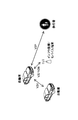
- FIG. 1 is a diagram for explaining V2X.
- V2X Vehicle to Everything
- eV2X enhanced V2X
- FIG. 1 V2X is a part of ITS (Intelligent Transport Systems) and means V2V (Vehicle to to Vehicle), which means a form of communication performed between cars, and a roadside installed on the side of a car and a road.
- V2I Vehicle-to-Infrastructure
- RSU Rad-Side @ Unit
- V2N Vehicle-to-infrastructure
- Nomadic device and V2P (Vehicle to Pedestrian) meaning a form of communication between a car and a mobile terminal carried by a pedestrian.
- 3GPP is studying V2X using LTE or NR cellular communication and terminal-to-terminal communication. It is assumed that studies on L2 or NR V2X not limited to the 3GPP specifications will be made in the future. For example, ensuring interoperability, reducing costs by implementing higher layers, using or switching multiple RATs (Radio Access Technology), supporting regulations in each country, acquiring data from LTE or NR V2X platforms, distributing, managing databases, It is assumed that usage methods will be considered.
- RATs Radio Access Technology
- the communication device may be a terminal held by a person, the communication device may be a device mounted on a drone or an aircraft, or the communication device may be a base station, an RSU, a relay station (relay node), or the like. It may be.
- SL may be distinguished from UL (Uplink) or DL (Downlink) based on any one or combination of the following 1) -4).
- SL may be another name. 1) Resource allocation in time domain 2) Resource allocation in frequency domain 3) Reference synchronization signal (including SLSS (Sidelink Synchronization Signal)) 4) Reference signal used for path loss measurement for transmission power control
- SL or UL OFDM Orthogonal Frequency Division Multiplexing
- CP-OFDM Cyclic-Prefix OFDM
- DFT-S-OFDM Discrete Fourier Transform-Spread-OFDM
- Transform not pre-coded or non-transformed non-transformed OFDM Any of the available OFDMs may be applied.
- Mode 3 and Mode 4 are defined for SL resource allocation to the user apparatus 20.
- transmission resources are dynamically allocated by DCI (Downlink ⁇ Control ⁇ Information) transmitted from the base station apparatus 10 to the user apparatus 20.
- DCI Downlink ⁇ Control ⁇ Information
- SPS Semi-Persistent Scheduling
- the user device 20 autonomously selects a transmission resource from the resource pool.
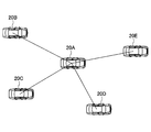
- FIG. 2 is a diagram illustrating an example of a wireless communication system according to an embodiment of the present invention.
- FIG. 2 shows an example in which the wireless communication system includes five user devices 20A, 20B, 20C, 20D, and 20E and performs SL communication with each other.
- the user device 20A can perform SL communication by unicast with any of the user devices 20B, 20C, 20D, and 20E. Further, for example, when the user devices 20B and 20C constitute a group, the user device 20A may perform SL communication with the user devices 20B and 20C by group cast. Also, the user device 20A may perform SL communication by broadcast with all of the user devices 20B, 20C, 20D, and 20E.
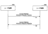
- FIG. 3 is a sequence diagram for explaining an example of side link communication in the embodiment of the present invention.
- the user apparatus 20A determines that the SLSS (Sidelink Synchronization Signal), the PSBCH (Physical Sidelink Broadcast Channel), the PSCCH (Physical Sidelink Control Channel), the PSSCH (Physical Sidelink Shared Channel) and / or the PSDCH (Physical Sidelink Discovery Channel).
- the wireless signal to be arranged is transmitted to the user device 20B.
- the user apparatus 20B receives the SLSS and the PSBCH, acquires control information necessary for synchronization and transmission / reception, and receives data via the PSSCH scheduled by the PSCCH.
- SLSS And / or PSBCH may be omitted.
- the user device 20B transmits a radio signal in which the SLSS, PSBCH, PSCCH, PSSCH, and / or PSDCH is arranged to the user device 20A.
- the user apparatus 20A receives and synchronizes the SLSS and the PSBCH, and receives data via the PSSCH scheduled by the PSCCH.
- synchronization can be obtained by another method and / or when necessary control information can be obtained (for example, synchronization using a signal transmitted from the base station apparatus 10 or GNSS, broadcast information acquisition, etc.)
- SLSS and / or PSBCH are omitted It may be done.
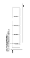
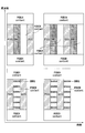
- FIG. 4 is a diagram showing an example (1) of the channel arrangement of the side link.
- the vertical axis corresponds to the frequency domain
- the horizontal axis corresponds to the time domain.
- User device 20 can transmit SLSS and PSBCH to operate as a synchronization source.
- SLSS and PSBCH are multiplexed and occupy one subframe.
- the subframe in which the SLSS and the PSBCH are arranged is excluded from the side link resources in which the PSCCH or the PSSCH is arranged.
- FIG. 5 is a diagram showing an example (2) of the channel arrangement of the side link.
- the user equipment 20 cannot transmit and receive data. For this reason, for example, in realizing URL-ULC (Ultra-Reliable and Low Latency Communication) in side link communication, it may be a factor that limits scheduling.
- URL-ULC Ultra-Reliable and Low Latency Communication
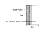
- FIG. 6 is a diagram showing an example (1) of the channel arrangement according to the embodiment of the present invention.
- SLSS and / or PSBCH and PSCCH, PSSCH and / or PSDCH may be set or pre-defined so that they are multiplexed in one slot.
- a gap also referred to as Guard @ Period
- SLSS and / or PSBCH and PSCCH, PSSCH and / or PSDCH may be set or pre-defined so that they are multiplexed in one slot.
- a gap also referred to as Guard @ Period
- SLSS and / or PSBCH may be provided between a resource in which the SLSS and / or PSBCH is arranged and a resource in which the PSCCH, PSSCH, and / or PSDCH are arranged.
- the arrangement order of SLSS and / or PSBCH and PSCCH, PSSCH and / or PSDCH does not matter.
- the resource in which the SLSS and / or the PSBCH is arranged may be defined so as to be excluded from the resources in which the PSCCH, the PSSCH and / or the PSDCH are arranged. All the symbols on which the SLSS and / or PSBCH are arranged may be excluded from the resources on which the PSCCH, PSSCH and / or PSDCH are arranged. Alternatively, only RE (Resource element), REG (Resource element group), PRB (Physical resource block) or sub-channel in which SLSS and / or PSBCH are arranged are excluded from resources in which PSCCH, PSSCH and / or PSDCH are arranged. May be done.
- the PSCCH, PSSCH and / or PSDCH may be frequency division multiplexed and / or time division multiplexed with SLSS and / or PSBCH.
- SLSS and / or PSBCH is preferentially allocated to the resource where PSCCH, PSSCH and / or PSDCH is initially allocated, execution of rate matching or puncturing may be set or specified in advance.
- the user apparatus 20 transmits the SLSS and / or PSBCH After that, when receiving the PSCCH, PSSCH and / or PSDCH multiplexed in the same slot, the switching time of the RF circuit or the like can be secured. Similarly, after the user apparatus 20 receives the SLSS and / or the PSBCH and transmits the PSCCH, the PSSCH and / or the PSDCH multiplexed in the same slot, the switching time of the RF circuit or the like can be secured.
- Transmission of SLSS and / or PSBCH may not be performed when there is a side link resource in which another SLSS and / or PSBCH transmitted from a common source exists.
- Waveforms eg, application of Transform @ precoding
- Numerology or BWP Bitwidth @ part
- SLSS and / or PSBCH and PSCCH, PSSCH and / or PSDCH may be set or defined in advance.
- UL or DL waveforms, numerology or BWP settings may be reused.
- the “slot” may be replaced with any resource unit corresponding to the time domain.
- a plurality of slots, one or a plurality of slots, one or a plurality of subframes, one or a plurality of TTIs (Transmission @ Time @ Interval), one or a plurality of short TTIs (sTTIs), and one or a plurality of symbols are arranged in a time domain. It may be a corresponding resource unit.
- the user device 20 may execute the following operations 1) to 6) according to the definition or setting based on the UE capability and specifications.
- the user apparatus 20 monitors both SLSS and / or PSBCH and PSCCH, PSSCH and / or PSDCH in a slot where SLSS and / or PSBCH and PSCCH, PSSCH and / or PSDCH are multiplexed. . 2) The user device 20 transmits both SLSS and / or PSBCH and PSCCH, PSSCH and / or PSDCH in a slot where SLSS and / or PSBCH and PSCCH, PSSCH and / or PSDCH are multiplexed. .
- the user apparatus 20 monitors the SLSS and / or the PSBCH in the slot where the SLSS and / or the PSBCH is multiplexed with the PSCCH, the PSSCH, and / or the PSDCH, and transmits the PSCCH, the PSSCH, and / or the PSDCH.
- the user apparatus 20 transmits the SLSS and / or the PSBCH in the slot where the SLSS and / or the PSBCH is multiplexed with the PSCCH, the PSSCH and / or the PSDCH, and monitors the PSCCH, the PSSCH and / or the PSDCH.
- the user apparatus 20 may skip the monitoring of the SLSS and / or the PSBCH when the side link resource in which the other SLSS and / or the PSBCH transmitted from the common source is available. 6) The user device 20 may skip the monitoring of the SLSS when another synchronization signal transmitted from the base station device 10 or the GNSS is available.
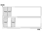
- FIG. 7 is a diagram showing an example (2) of the channel arrangement in the embodiment of the present invention.
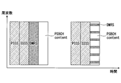
- SLSS includes PSSS (Primary Sidelink Synchronization Signal) and SSSS (Secondary Sidelink Synchronization Signal)
- PSBCH includes DMRS (Demodulation reference signal) and PSBCH content.
- FIGS. 7 to 13 the arrangement order of signals to be multiplexed using time division multiplexing and / or frequency division multiplexing does not matter.
- FIG. 7 illustrates the order of PSSS and SSSS. However, the order may be SSSS and PSSS.
- PSSS and SSSS may be time division multiplexed. As shown in FIG. 7, PSSS and SSSS may be arranged in adjacent slots or symbols, or may be arranged in non-adjacent slots or symbols.
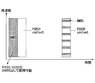
- FIG. 8 is a diagram showing an example (3) of the channel arrangement in the embodiment of the present invention.
- the contents of DMRS and PSBCH may be frequency division multiplexed within a single symbol, or may be time division multiplexed with different symbols.
- the specification may define that the PSSS or the SSSS is used as the DMRS and the normal DMRS is not arranged.
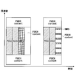
- FIG. 9 is a diagram showing an example (1) of a channel arrangement by time division multiplexing in the embodiment of the present invention.
- FIG. 9 shows an example in which PSSS and SSSS are arranged in adjacent symbols, and SLSS and PSBCH are time-division multiplexed.
- symbol #n represents the n-th symbol.
- the contents of PSSS may be arranged in symbol # 1, the SSSS in symbol # 2, the DMRS in symbol # 3, and the PSBCH in symbol # 4.
- the contents of the PSSS in symbol # 1, the SSSS in symbol # 2, and the contents of DMRS and PSBCH frequency-division multiplexed in symbol # 3 may be arranged.
- FIG. 10 is a diagram showing an example (2) of a channel arrangement by time division multiplexing in the embodiment of the present invention.
- FIG. 10 shows an example in which PSSS and SSSS are arranged in non-adjacent symbols, and SLSS and PSBCH are time-division multiplexed.
- PSSS may be arranged in symbol # 1, DMRS in symbol # 2, PSBCH content in symbol # 3, and SSSS in symbol # 4.
- PSSS is used for symbol # 1
- DMRS is used for symbol # 2
- PSBCH content is used for symbol # 3
- SSSS is used for symbol # 4
- DMRS is used for symbol # 5
- symbol # 5 symbol # 5. 6
- the contents of the PSBCH may be arranged.
- PSSS may be arranged in symbol # 1
- SSSS may be arranged in symbol # 3.
- the contents of the PSSS for symbol # 1 the contents of DMRS and PSBCH frequency-division multiplexed for symbol # 2, the SSSS for symbol # 3, and the frequency division multiplexing for symbol # 4.
- the contents of the assigned DMRS and PSBCH may be arranged.
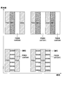
- FIG. 11 is a diagram showing an example of channel arrangement by frequency division multiplexing in the embodiment of the present invention.
- FIG. 11 shows an example in which SLSS and PSBCH are frequency division multiplexed.
- DMRS, PSSS, and DMRS are sequentially arranged in symbol # 1 in the frequency domain, and the contents of PSBCH, SSSS, and PSBCH are arranged in symbol # 2 in the frequency domain. May be done. Further, as shown in FIG.
- the contents of DMRS and PSBCH, which are frequency-division multiplexed in the frequency domain, the PSSS, and the contents of DMRS and PSBCH, which are frequency-division multiplexed are arranged in symbol # 1.
- symbol # 2 the contents of DMRS and PSBCH frequency-division multiplexed in the frequency domain, the SSSS, and the contents of DMRS and PSBCH frequency-division multiplexed may be arranged.
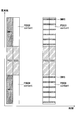
- FIG. 12 is a diagram showing an example (1) of channel arrangement by time division multiplexing and frequency division multiplexing in the embodiment of the present invention.
- FIG. 12 shows an example in which PSSS and SSSS are arranged in adjacent symbols, and SLSS and PSBCH are time division multiplexed and frequency division multiplexed.
- the contents of the PSBCH are arranged at both ends of the frequency domain of the entire four symbols, and in the central part of the frequency domain, the symbol # 1 is PSSS, the symbol # 2 is SSSS, and the symbol is SSSS.
- the contents of DMRS may be arranged in # 3 and the contents of PSBCH may be arranged in symbol # 4. Also, as shown in FIG.
- the contents of the PSBCH are arranged at both ends of the frequency domain of all three symbols, and in the central part of the frequency domain, PSSS is assigned to symbol # 1 and SSSS is assigned to symbol # 2.
- Symbol # 3 the contents of DMRS and PSBCH frequency-division multiplexed may be arranged.
- FIG. 13 is a diagram showing an example (2) of the channel arrangement by time division multiplexing and frequency division multiplexing in the embodiment of the present invention.
- FIG. 13 shows an example in which PSSS and SSSS are arranged in symbols that are not adjacent to each other, and SLSS and PSBCH are time division multiplexed and frequency division multiplexed.
- the contents of PSBCH are arranged at both ends of the frequency domain of the entire 4 symbols, and in the center of the frequency domain, PSSS is assigned to symbol # 1, DMRS is assigned to symbol # 2, and symbol
- the contents of PSBCH may be arranged in # 3, and the SSSS may be arranged in symbol # 4.
- FIG. 13 shows an example in which PSSS and SSSS are arranged in symbols that are not adjacent to each other, and SLSS and PSBCH are time division multiplexed and frequency division multiplexed.
- the contents of PSBCH are arranged at both ends of the frequency domain of the entire 4 symbols, and in the center of the frequency domain, PSSS
- the contents of PSBCH are arranged at both ends of the frequency domain of the entire 6 symbols, and PSSS is assigned to symbol # 1 and DMRS is assigned to symbol # 2 in the center of the frequency domain.
- Symbol # 3 the contents of PSBCH may be arranged in symbol # 4, the SSSS in symbol # 5, the DMRS in symbol # 5, and the contents of PSBCH in symbol # 6.
- the contents of the PSBCH are arranged at both ends of the frequency domain of all three symbols, and in the central part of the frequency domain, PSSS is assigned to symbol # 1 and frequency is assigned to symbol # 2.
- the SSSS may be arranged in the content of the division multiplexed DMRS and PSBCH, and symbol # 3. Further, as shown in FIG. 13, in the resource of three symbols, the contents of the PSBCH are arranged at both ends of the frequency domain of all three symbols, and in the central part of the frequency domain, PSSS is assigned to symbol # 1 and frequency is assigned to symbol # 2.
- the SSSS may be arranged in the content of the division multiplexed DMRS and PSBCH, and symbol # 3. Further, as shown in FIG.
- the contents of the PSBCH are arranged at both ends of the frequency domain of the entire four symbols, and in the center of the frequency domain, PSSS is assigned to symbol # 1 and frequency is assigned to symbol # 2
- the content of the division multiplexed DMRS and PSBCH, the SSSS in symbol # 3, and the content of the DMRS and PSBCH frequency division multiplexed in symbol # 4 may be arranged.
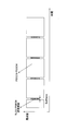
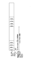
- FIG. 14 is a diagram illustrating an example (1) of an arrangement of synchronization signals according to the embodiment of the present invention.
- Transmission of one or more SLSS and / or PSBCH for each synchronization signal transmission opportunity may be configurable.
- the transmission of SLSS and / or PSBCH may be defined as SL-SSB (SL-Sychronization signal block).
- the number of SL-SSB repetitions for each synchronization signal transmission opportunity may be set or predetermined. Further, the number of SL-SSB repetitions per slot may be set or predetermined.
- PHY layer and / or higher layer signaling may be used for SL-SSB configuration. For example, DCI or RRC (Radio Resource Control) signaling may be used for SL-SSB configuration.
- the settings or rules of the DL SS / PBCH block may be used for the settings or rules related to the SL-SSB.
- the DL setting or specification may be used for part or all of the setting or specification related to the multiplexing of the SLSS / PSBCH and the PSCCH / PSSCH / PSDCH described with reference to FIGS.
- FIG. 14 shows an example in which four SL-SSBs are arranged per transmission opportunity of a synchronization signal and one SL-SSB is arranged per slot.
- Resources for which the SL-SSB is not allocated may allocate the PSCCH, the PSSCH and / or the PSDCH. Since the PSCCH and / or PSSCH can be arranged in any slot, it is possible to cope with URLLC traffic.
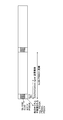
- FIG. 15 is a diagram illustrating an example (2) of an arrangement of synchronization signals according to the embodiment of the present invention.
- FIG. 15 shows an example in which four SL-SSBs are arranged per synchronization signal transmission opportunity and four SL-SSBs are arranged per slot.
- Resources for which the SL-SSB is not allocated may allocate the PSCCH, the PSSCH and / or the PSDCH.
- the PSCCH, PSSCH and / or PSDCH can be arranged in any slot, it is possible to cope with URLLC traffic.
- the user apparatus 20 can multiplex and transmit and receive SLSS and / or PSBCH and PSCCH, PSSCH and / or PSDCH in the same slot.
- the base station device 10 and the user device 20 include a function for implementing the above-described embodiment. However, each of the base station device 10 and the user device 20 may include only some of the functions in the embodiment.
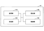
- FIG. 16 is a diagram illustrating an example of a functional configuration of the base station device 10.
- base station apparatus 10 includes transmitting section 110, receiving section 120, setting section 130, and control section 140.
- the functional configuration shown in FIG. 16 is only an example. As long as the operation according to the embodiment of the present invention can be executed, the names of the functional divisions and the functional units may be any.
- the transmission unit 110 has a function of generating a signal to be transmitted to the user device 20 and transmitting the signal wirelessly.
- the receiving unit 120 includes a function of receiving various signals transmitted from the user device 20 and acquiring, for example, information of a higher layer from the received signals.
- the transmitting unit 110 has a function of transmitting an NR-PSS, an NR-SSS, an NR-PBCH, a DL / UL control signal, and the like to the user device 20. Further, for example, the transmitting unit 110 transmits information indicating that another terminal is approaching the user device 20, and the receiving unit 120 receives terminal information from the user device 20.
- the setting unit 130 stores in the storage device the setting information set in advance and various setting information to be transmitted to the user device 20, and reads out the setting information from the storage device as needed.
- the content of the setting information is, for example, information related to channel setting of D2D communication.
- the control unit 140 performs the process related to the setting for the user device 20 to perform the D2D communication, as described in the embodiment.
- a function unit related to signal transmission in control unit 140 may be included in transmitting unit 110, and a function unit related to signal reception in control unit 140 may be included in receiving unit 120.
- FIG. 17 is a diagram illustrating an example of a functional configuration of the user device 20.
- the user device 20 includes a transmitting unit 210, a receiving unit 220, a setting unit 230, and a control unit 240.
- the functional configuration shown in FIG. 17 is only an example. As long as the operation according to the embodiment of the present invention can be executed, the names of the functional divisions and the functional units may be any.
- the transmission unit 210 creates a transmission signal from transmission data, and transmits the transmission signal wirelessly.
- the receiving unit 220 wirelessly receives various signals and obtains a higher-layer signal from the received physical-layer signal.
- the receiving section 220 has a function of receiving NR-PSS, NR-SSS, NR-PBCH, DL / UL / SL control signals, and the like transmitted from the base station apparatus 10.
- the transmission unit 210 transmits the PSCCH (Physical Sidelink Shared Channel), the PSSCH (Physical Sidelink Shared Channel), the PSDCH (Physical Sidelink Discovery Channel), and the PSBCH (Physical Sidelink Broadcast Channel) to another user device 20 as D2D communication. )
- the receiving unit 120 receives a PSCCH, a PSSCH, a PSDCH, a PSBCH, or the like from another user apparatus 20.
- the setting unit 230 stores various setting information received from the base station device 10 or the user device 20 by the receiving unit 220 in a storage device, and reads out the setting information from the storage device as needed.
- the setting unit 230 also stores preset setting information.
- the content of the setting information is, for example, information related to channel setting of D2D communication.
- the control unit 240 controls the D2D communication performed with another user device 20 as described in the embodiment. In addition, the control unit 240 executes transmission / reception processing via each channel of D2D communication.
- a function unit related to signal transmission in control unit 240 may be included in transmission unit 210, and a function unit related to signal reception in control unit 240 may be included in reception unit 220.
- each functional block may be realized by one device in which a plurality of elements are physically and / or logically combined, or two or more devices physically and / or logically separated from each other directly and And / or indirectly (for example, wired and / or wireless), and may be implemented by these multiple devices.
- both the base station device 10 and the user device 20 according to an embodiment of the present invention may function as a computer that performs processing according to the embodiment of the present invention.
- FIG. 18 is a diagram illustrating an example of a hardware configuration of a wireless communication device that is the base station device 10 or the user device 20 according to the embodiment of the present invention.
- Each of the above-described base station device 10 and user device 20 is physically a computer device including a processor 1001, a storage device 1002, an auxiliary storage device 1003, a communication device 1004, an input device 1005, an output device 1006, a bus 1007, and the like. It may be configured.
- the term “apparatus” can be read as a circuit, a device, a unit, or the like.
- the hardware configuration of the base station device 10 and the user device 20 may be configured to include one or more of the devices indicated by 1001 to 1006 illustrated in the drawing, or may be configured without including some devices. May be done.
- the functions of the base station device 10 and the user device 20 are performed by reading predetermined software (program) on hardware such as the processor 1001 and the storage device 1002, so that the processor 1001 performs an arithmetic operation. This is realized by controlling reading and / or writing of data in the storage device 1002 and the auxiliary storage device 1003.
- the processor 1001 controls the entire computer by operating an operating system, for example.
- the processor 1001 may be configured by a central processing unit (CPU: Central Processing Unit) including an interface with a peripheral device, a control device, an arithmetic device, a register, and the like.
- CPU Central Processing Unit
- the processor 1001 reads a program (program code), a software module, or data from the auxiliary storage device 1003 and / or the communication device 1004 to the storage device 1002, and executes various processes according to these.
- a program program that causes a computer to execute at least a part of the operation described in the above embodiment is used.
- the transmission unit 110, the reception unit 120, the setting unit 130, and the control unit 140 of the base station device 10 illustrated in FIG. 16 may be realized by a control program stored in the storage device 1002 and operated by the processor 1001.
- Process 17 are realized by a control program stored in the storage device 1002 and operated by the processor 1001. Is also good. Although it has been described that the various processes described above are executed by one processor 1001, the processes may be executed simultaneously or sequentially by two or more processors 1001. Processor 1001 may be implemented with one or more chips. Note that the program may be transmitted from a network via a telecommunication line.
- the storage device 1002 is a computer-readable recording medium, and is, for example, at least one of a ROM (Read Only Memory), an EPROM (Erasable Programmable ROM), an EEPROM (Electrically Erasable Programmable ROM), and a RAM (Random Access Memory). It may be configured.
- the storage device 1002 may be called a register, a cache, a main memory (main storage device), or the like.
- the storage device 1002 can store a program (program code), a software module, and the like that can be executed to execute the processing according to an embodiment of the present invention.
- the auxiliary storage device 1003 is a computer-readable recording medium, for example, an optical disk such as a CD-ROM (Compact Disc ROM), a hard disk drive, a flexible disk, a magneto-optical disk (for example, a compact disk, a digital versatile disk, Blu -Ray (registered trademark) disk), smart card, flash memory (eg, card, stick, key drive), floppy (registered trademark) disk, magnetic strip, or the like.
- the auxiliary storage device 1003 may be called an auxiliary storage device.
- the storage medium described above may be, for example, a database including the storage device 1002 and / or the auxiliary storage device 1003, a server, or any other appropriate medium.
- the communication device 1004 is hardware (transmitting / receiving device) for performing communication between computers via a wired and / or wireless network, and is also referred to as, for example, a network device, a network controller, a network card, a communication module, and the like.
- the transmitting unit 110 and the receiving unit 120 of the base station device 10 may be realized by the communication device 1004.
- the transmission unit 210 and the reception unit 220 of the user device 20 may be realized by the communication device 1004.
- the input device 1005 is an input device (for example, a keyboard, a mouse, a microphone, a switch, a button, a sensor, and the like) that receives an external input.
- the output device 1006 is an output device (for example, a display, a speaker, an LED lamp, and the like) that performs output to the outside. Note that the input device 1005 and the output device 1006 may have an integrated configuration (for example, a touch panel).
- the devices such as the processor 1001 and the storage device 1002 are connected by a bus 1007 for communicating information.
- the bus 1007 may be configured by a single bus, or may be configured by a different bus between the devices.
- the base station device 10 and the user device 20 are respectively a microprocessor, a digital signal processor (DSP: Digital Signal Processor), an ASIC (Application Specific Integrated Circuit), a PLD (Programmable Logic Device), an FPGA (Field Programmable Gate Array), and the like. And some or all of the functional blocks may be realized by the hardware.
- the processor 1001 may be implemented by at least one of these hardware.
- At least one of a user SLSS (Sidelink syncronization signal) and a PSBCH (Physical Sidelink Broadcast Channel) is arranged via direct communication between terminals.
- a side link in which a resource and a second resource in which at least one of a PSCCH (Physical Sidelink Control Channel), a PSSCH (Physical Sidelink Shared Channel) and a PSDCH (Physical Sidelink Discovery Channel) is arranged are multiplexed in the same slot.
- a control unit that performs control related to transmission or reception of a signal, and the first resource, the second resource, the first resource, and the second resource, a receiving unit that monitors one of the: Out of the first resource, the second resource, the first resource, and the second resource,
- a user device having a transmission unit for transmitting using any one of them is provided.
- the user apparatus 20 can multiplex and transmit / receive SLSS and / or PSBCH and PSCCH, PSSCH and / or PSDCH in the same slot. That is, in direct communication between terminals, flexible scheduling can be performed.
- the monitoring of the first resource may not be performed.
- the user device 20 can stop unnecessary monitoring and reduce power consumption.
- the user device 20 can stop unnecessary monitoring and reduce power consumption.
- GNSS Global Navigation Satellite System
- the first resource and the second resource may be time-division multiplexed, and a gap may be arranged in a time domain between the first resource and the second resource.
- the user device 20 can secure a switching time for the RF circuit and the like.
- the SLSS arranged in the first resource includes a Primary Sidelink Synchronization Signal (PSSS) and a Secondary Sidelink Synchronization Signal (SSSS), and the PSBCH arranged in the first resource is a demodulation reference signal and a PSBCH.
- PSSS Primary Sidelink Synchronization Signal
- SSSS Secondary Sidelink Synchronization Signal
- the PSBCH arranged in the first resource is a demodulation reference signal and a PSBCH.
- the PSSS or SSSS is used as the DMRS.
- the user apparatus 20 can reduce resource consumption by demodulating the PSBCH using the PSSS or the SSSS instead of the normal DMRS.
- the PSBCH allocated to the first resource is configured by frequency division multiplexing of DMRS and the contents of the PSBCH, and is configured by frequency division multiplexing of SLSS and PSBCH allocated to the first resource. Is also good. With this configuration, the user apparatus 20 can transmit and receive the SLSS and the PSBCH by frequency division multiplexing.
- the operation of a plurality of functional units may be physically performed by one component, or the operation of one functional unit may be physically performed by a plurality of components.
- the order of the processing may be changed as long as there is no contradiction.
- the base station device 10 and the user device 20 have been described using a functional block diagram for convenience of processing description, such a device may be realized by hardware, software, or a combination thereof.
- the software operated by the processor of the base station apparatus 10 according to the embodiment of the present invention and the software operated by the processor of the user apparatus 20 according to the embodiment of the present invention are a random access memory (RAM), a flash memory, and a read memory, respectively.
- the data may be stored in a dedicated memory (ROM), EPROM, EEPROM, register, hard disk (HDD), removable disk, CD-ROM, database, server, or any other suitable storage medium.
- the notification of information is not limited to the aspect / embodiment described in this specification, and may be performed by another method.
- the notification of information includes physical layer signaling (for example, DCI (Downlink Control Information), UCI (Uplink Control Information)), upper layer signaling (for example, RRC (Radio Resource Control) signaling, MAC (Medium Access Control) signaling, RRC signaling may be implemented by broadcast information (MIB (Master Information Block), SIB (System Information Block)), other signals, or a combination thereof, and RRC signaling may be referred to as an RRC message.
- a connection setup (RRC (Connection Setup) message, an RRC connection reconfiguration (RRC Connection Reconfiguration) message, or the like may be used.
- Each aspect / embodiment described in this specification includes LTE (Long Term Evolution), LTE-A (LTE-Advanced), SUPER 3G, IMT-Advanced, 4G, 5G, FRA (Future Radio Access), W-CDMA.
- LTE Long Term Evolution
- LTE-A Long Term Evolution-Advanced
- SUPER 3G IMT-Advanced
- 4G 5G
- FRA Full Radio Access
- W-CDMA Wideband
- GSM registered trademark
- CDMA2000 Code Division Multiple Access 2000
- UMB User Mobile Broadband
- IEEE 802.11 Wi-Fi
- IEEE 802.16 WiMAX
- IEEE 802.20 UWB (Ultra-WideBand
- the present invention may be applied to a system using Bluetooth (registered trademark), another appropriate system, and / or a next-generation system extended based on the system.
- the specific operation described as being performed by the base station device 10 in this specification may be performed by an upper node (upper node) in some cases.
- an upper node In a network including one or a plurality of network nodes (network @ nodes) including the base station device 10, various operations performed for communication with the user device 20 are different from the base station device 10 and / or the base station device 10. It is clear that this can be done by other network nodes (for example, but not limited to MME or S-GW etc.).
- MME Mobility Management Entity
- the user equipment 20 may be provided by one of ordinary skill in the art to a subscriber station, mobile unit, subscriber unit, wireless unit, remote unit, mobile device, wireless device, wireless communication device, remote device, mobile subscriber station, access terminal, mobile terminal, It may also be called a wireless terminal, remote terminal, handset, user agent, mobile client, client, or some other suitable term.
- Base station device 10 may also be referred to by those skilled in the art as NB (NodeB), eNB (evolved NodeB), gNB (next generation eNB), base station (Base Station), or some other suitable terminology.
- NB NodeB
- eNB evolved NodeB
- gNB next generation eNB
- Base Station Base station device 10 may also be referred to by those skilled in the art as NB (NodeB), eNB (evolved NodeB), gNB (next generation eNB), base station (Base Station), or some other suitable terminology.
- determining may encompass a wide variety of operations. “Judgment” and “decision” are, for example, judgment (judging), calculation (computing), processing (processing), deriving (investigating), and investigating (looking up) (for example, a table). , A search in a database or another data structure), ascertaining, etc. may be considered as “determined”, “determined”, etc. Also, “determining” and “determining” refer to receiving (eg, receiving information), transmitting (eg, transmitting information), input (input), output (output), access (Accessing) (e.g., accessing data in the memory) may be regarded as “determined” or "determined”.
- judgment and “decision” mean that resolving, selecting, choosing, choosing, establishing, comparing, etc. are regarded as “judgment” and “determined”. May be included. In other words, “judgment” and “decision” may include deeming any operation as “judgment” and “determined”.
- the SLSS is a synchronization signal for the side link, and may be referred to as a synchronization signal for D2D.
- the PSBCH is a broadcast channel for a side link for transmitting system information and the like, and may be called a broadcast channel for D2D.
- the PSCCH is a control channel for a side link for transmitting a control signal and the like, and may be referred to as a D2D control channel.
- the PSSCH is a side link shared channel for transmitting data and the like, and may be referred to as a D2D shared channel.
- the PSDCH is a discovery channel for a side link used for terminal discovery, and may be referred to as a discovery channel for D2D.
Landscapes
- Engineering & Computer Science (AREA)
- Signal Processing (AREA)
- Computer Networks & Wireless Communication (AREA)
- Mobile Radio Communication Systems (AREA)
Abstract
Un dispositif utilisateur comprend : une unité de commande qui effectue une commande concernant la transmission ou la réception de signaux de liaison latérale ayant une première ressource et une seconde ressource multiplexées dans le même intervalle de temps, ladite première ressource ayant au moins un signal de synchronisation de liaison latérale (SLSS) ou un canal de diffusion de liaison latérale physique (PSBCH) disposé en son sein et ladite seconde ressource ayant au moins un canal de commande de liaison latérale physique (PSCCH), un canal partagé de liaison latérale physique (PSSCH) ou un canal de découverte de liaison latérale physique (PSDCH) disposé en son sein ; une unité de réception qui surveille la première ressource, la seconde ressource ou la première ressource et la seconde ressource ; et une unité de transmission qui transmet à l'aide de la première ressource, de la seconde ressource ou de la première ressource et de la seconde ressource.
Priority Applications (5)
| Application Number | Priority Date | Filing Date | Title |
|---|---|---|---|
| PCT/JP2018/030146 WO2020031384A1 (fr) | 2018-08-10 | 2018-08-10 | Dispositif utilisateur |
| EP18929613.0A EP3836667A4 (fr) | 2018-08-10 | 2018-08-10 | Dispositif utilisateur |
| CN201880096254.4A CN112534903B (zh) | 2018-08-10 | 2018-08-10 | 用户装置 |
| JP2020535474A JP7132334B2 (ja) | 2018-08-10 | 2018-08-10 | 端末及び通信方法 |
| US17/264,128 US11924831B2 (en) | 2018-08-10 | 2018-08-10 | User equipment (UE) for performing flexible scheduling for inter-terminal direct communication |
Applications Claiming Priority (1)
| Application Number | Priority Date | Filing Date | Title |
|---|---|---|---|
| PCT/JP2018/030146 WO2020031384A1 (fr) | 2018-08-10 | 2018-08-10 | Dispositif utilisateur |
Publications (1)
| Publication Number | Publication Date |
|---|---|
| WO2020031384A1 true WO2020031384A1 (fr) | 2020-02-13 |
Family
ID=69414606
Family Applications (1)
| Application Number | Title | Priority Date | Filing Date |
|---|---|---|---|
| PCT/JP2018/030146 Ceased WO2020031384A1 (fr) | 2018-08-10 | 2018-08-10 | Dispositif utilisateur |
Country Status (5)
| Country | Link |
|---|---|
| US (1) | US11924831B2 (fr) |
| EP (1) | EP3836667A4 (fr) |
| JP (1) | JP7132334B2 (fr) |
| CN (1) | CN112534903B (fr) |
| WO (1) | WO2020031384A1 (fr) |
Cited By (7)
| Publication number | Priority date | Publication date | Assignee | Title |
|---|---|---|---|---|
| WO2021237654A1 (fr) | 2020-05-29 | 2021-12-02 | Qualcomm Incorporated | Multiplexage d'un bloc de signal de synchronisation de liaison latérale (s-ssb) et d'un canal de commande de liaison latérale physique/canal partagé de liaison latérale physique (pscch/pscch) et gestion optimale d'une largeur de bande de canal d'occupation (ocb) pour une liaison latérale de nouvelle radio sans licence (nr-u) |
| CN113939035A (zh) * | 2020-06-29 | 2022-01-14 | 上海朗帛通信技术有限公司 | 一种用于无线通信的节点中的方法和装置 |
| WO2022011600A1 (fr) | 2020-07-15 | 2022-01-20 | Qualcomm Incorporated | Techniques de conception de forme d'onde de bloc de signal de synchronisation pour communications de liaison latérale |
| US20220191875A1 (en) * | 2019-04-01 | 2022-06-16 | Apple Inc. | Pscch control channel design for nr v2x sidelink communication and pscch dmrs physical structures |
| EP4161185A4 (fr) * | 2020-05-29 | 2023-07-19 | Guangdong Oppo Mobile Telecommunications Corp., Ltd. | Procédé de communication sans fil et dispositif terminal |
| US20230345305A1 (en) * | 2020-04-22 | 2023-10-26 | Ntt Docomo, Inc. | Terminal and communication method |
| US12621780B2 (en) | 2020-05-29 | 2026-05-05 | Qualcomm Incorporated | Multiplexing sidelink-synchronization signal block (S-SSB) and physical sidelink control channel/physical sidelink shared channel (PSCCH/PSCCH) and fulfilment of occupancy channel bandwidth (OCB) for new radio-unlicensed (NR-U) sidelink |
Families Citing this family (3)
| Publication number | Priority date | Publication date | Assignee | Title |
|---|---|---|---|---|
| WO2020091555A1 (fr) * | 2018-11-02 | 2020-05-07 | 엘지전자 주식회사 | Procédé d'émission et de réception de signaux dans un système de communication sans fil et dispositif prenant en charge ledit procédé |
| CN111586623B (zh) * | 2019-02-15 | 2024-06-18 | 华为技术有限公司 | 通信方法和通信装置 |
| US12041564B2 (en) * | 2020-05-22 | 2024-07-16 | Qualcomm Incorporated | Demand and response for sidelink synchronization signal block (S-SSB) transmission |
Citations (2)
| Publication number | Priority date | Publication date | Assignee | Title |
|---|---|---|---|---|
| WO2017057321A1 (fr) * | 2015-10-02 | 2017-04-06 | 株式会社Nttドコモ | Équipement d'utilisateur et procédé de synchronisation |
| WO2018012614A1 (fr) * | 2016-07-15 | 2018-01-18 | シャープ株式会社 | Dispositif terminal et procédé |
Family Cites Families (20)
| Publication number | Priority date | Publication date | Assignee | Title |
|---|---|---|---|---|
| JP5606836B2 (ja) * | 2010-08-31 | 2014-10-15 | 株式会社Nttドコモ | 無線通信システム及び移動端末装置 |
| WO2016047753A1 (fr) * | 2014-09-26 | 2016-03-31 | シャープ株式会社 | Dispositif terminal, dispositif de station de base, procédé de communication et circuit intégré |
| KR102078424B1 (ko) * | 2014-11-07 | 2020-02-19 | 이노스카이 주식회사 | 무선 통신 시스템에서 단말간 통신채널을 전송하는 장치 및 방법 |
| CN107432011A (zh) * | 2015-03-31 | 2017-12-01 | 株式会社Ntt都科摩 | 用户装置以及控制信息发送方法 |
| CN105050152B (zh) * | 2015-07-14 | 2017-06-20 | 宇龙计算机通信科技(深圳)有限公司 | 一种基于d2d中继通信的业务处理方法及装置 |
| ES2871106T3 (es) * | 2015-08-13 | 2021-10-28 | Ntt Docomo Inc | Dispositivo de usuario y método de transmisión de señales |
| CN113329367B (zh) * | 2015-09-25 | 2024-06-14 | 创新技术实验室株式会社 | 用于为v2x配置dm-rs的方法和装置 |
| CN108141340B (zh) * | 2015-10-01 | 2020-11-24 | Lg 电子株式会社 | 在d2d通信中发送参考信号的方法和终端 |
| WO2017117811A1 (fr) * | 2016-01-08 | 2017-07-13 | 华为技术有限公司 | Procédé d'émission de signaux et dispositif de terminal |
| US10506402B2 (en) * | 2016-03-31 | 2019-12-10 | Samsung Electronics Co., Ltd. | Method and apparatus for transmission of control and data in vehicle to vehicle communication |
| WO2018004268A1 (fr) * | 2016-06-29 | 2018-01-04 | 엘지전자(주) | Procédé de réception d'un signal de rétroaction dans un système de communication sans fil et appareil associé |
| WO2018030185A1 (fr) * | 2016-08-10 | 2018-02-15 | ソニー株式会社 | Dispositif et procédé de communication |
| JP2018029323A (ja) * | 2016-08-10 | 2018-02-22 | ソニー株式会社 | 通信装置及び通信方法 |
| US20180092067A1 (en) * | 2016-09-28 | 2018-03-29 | Futurewei Technologies, Inc. | System and Method for D2D Communication |
| US10925019B2 (en) * | 2016-11-02 | 2021-02-16 | Ntt Docomo, Inc. | User terminal and radio communication method |
| CN108289325B (zh) * | 2017-01-09 | 2022-03-01 | 中兴通讯股份有限公司 | 上行和下行传输对齐的方法及装置 |
| RU2019125985A (ru) * | 2017-02-01 | 2021-03-02 | Нтт Докомо, Инк. | Пользовательский терминал и способ радиосвязи |
| US20190313271A1 (en) * | 2018-06-20 | 2019-10-10 | Intel Corporation | Apparatus, system and method of configuring new radio (nr) measurements |
| US10834708B2 (en) * | 2018-07-06 | 2020-11-10 | Samsung Electronics Co., Ltd. | Method and apparatus for NR sidelink SS/PBCH block |
| CN112567673B (zh) * | 2018-08-09 | 2024-07-26 | 交互数字专利控股公司 | 用于nr v2x的波束赋形和分组 |
-
2018
- 2018-08-10 JP JP2020535474A patent/JP7132334B2/ja active Active
- 2018-08-10 EP EP18929613.0A patent/EP3836667A4/fr active Pending
- 2018-08-10 US US17/264,128 patent/US11924831B2/en active Active
- 2018-08-10 CN CN201880096254.4A patent/CN112534903B/zh active Active
- 2018-08-10 WO PCT/JP2018/030146 patent/WO2020031384A1/fr not_active Ceased
Patent Citations (2)
| Publication number | Priority date | Publication date | Assignee | Title |
|---|---|---|---|---|
| WO2017057321A1 (fr) * | 2015-10-02 | 2017-04-06 | 株式会社Nttドコモ | Équipement d'utilisateur et procédé de synchronisation |
| WO2018012614A1 (fr) * | 2016-07-15 | 2018-01-18 | シャープ株式会社 | Dispositif terminal et procédé |
Non-Patent Citations (4)
| Title |
|---|
| 3GPP TR 22.886, March 2017 (2017-03-01) |
| 3GPP TS 36.211, June 2018 (2018-06-01) |
| NTT DOCOMO, INC: "Enhancements of LTE Uu and NR Uu to control NR sidelink", 3GPP TSG RAN WG1 #94 R1-1809160, 10 August 2018 (2018-08-10), XP051516530 * |
| ZTE: "Consideration on short TTI based PC5 operation", 3GPP TSG RAN WG2 #99 R2-1708511, 20 August 2017 (2017-08-20), XP051318366, Retrieved from the Internet <URL:http://www.3gpp.org/ftp/Meetings_3GPP_SYNC/RAN2/Docs/> * |
Cited By (17)
| Publication number | Priority date | Publication date | Assignee | Title |
|---|---|---|---|---|
| US12028884B2 (en) * | 2019-04-01 | 2024-07-02 | Apple Inc. | PSCCH control channel design for NR V2X sidelink communication and PSCCH DMRS physical structures |
| US20220191875A1 (en) * | 2019-04-01 | 2022-06-16 | Apple Inc. | Pscch control channel design for nr v2x sidelink communication and pscch dmrs physical structures |
| US20230345305A1 (en) * | 2020-04-22 | 2023-10-26 | Ntt Docomo, Inc. | Terminal and communication method |
| US12167279B2 (en) * | 2020-04-22 | 2024-12-10 | Ntt Docomo, Inc. | Terminal and communication method |
| EP4158969A4 (fr) * | 2020-05-29 | 2024-02-28 | Qualcomm Incorporated | Multiplexage d'un bloc de signal de synchronisation de liaison latérale (s-ssb) et d'un canal de commande de liaison latérale physique/canal partagé de liaison latérale physique (pscch/pscch) et gestion optimale d'une largeur de bande de canal d'occupation (ocb) pour une liaison latérale de nouvelle radio sans licence (nr-u) |
| EP4161185A4 (fr) * | 2020-05-29 | 2023-07-19 | Guangdong Oppo Mobile Telecommunications Corp., Ltd. | Procédé de communication sans fil et dispositif terminal |
| CN115589790A (zh) * | 2020-05-29 | 2023-01-10 | 高通股份有限公司 | 对侧行链路同步信号块(s-ssb)和物理侧行链路控制信道/物理侧行链路共享信道(pscch/pscch)进行复用以及用于新无线电未许可(nr-u)侧行链路的占用信道带宽(ocb)的实现 |
| WO2021237654A1 (fr) | 2020-05-29 | 2021-12-02 | Qualcomm Incorporated | Multiplexage d'un bloc de signal de synchronisation de liaison latérale (s-ssb) et d'un canal de commande de liaison latérale physique/canal partagé de liaison latérale physique (pscch/pscch) et gestion optimale d'une largeur de bande de canal d'occupation (ocb) pour une liaison latérale de nouvelle radio sans licence (nr-u) |
| US12471043B2 (en) | 2020-05-29 | 2025-11-11 | Guangdong Oppo Mobile Telecommunications Corp., Ltd. | Wireless communication method and terminal device for acquiring frequency domain resource information |
| TWI910169B (zh) * | 2020-05-29 | 2026-01-01 | 美商高通公司 | 對側行鏈路同步訊號塊(s-ssb)和實體側行鏈路控制通道/實體側行鏈路共享通道(pscch/pssch)進行多工處理以及用於新無線電未許可(nr-u)側行鏈路的佔用通道頻寛(ocb)的實現 |
| CN115589790B (zh) * | 2020-05-29 | 2026-04-03 | 高通股份有限公司 | 用于无线通信的方法、装置和非暂时性计算机可读介质 |
| US12621780B2 (en) | 2020-05-29 | 2026-05-05 | Qualcomm Incorporated | Multiplexing sidelink-synchronization signal block (S-SSB) and physical sidelink control channel/physical sidelink shared channel (PSCCH/PSCCH) and fulfilment of occupancy channel bandwidth (OCB) for new radio-unlicensed (NR-U) sidelink |
| CN113939035A (zh) * | 2020-06-29 | 2022-01-14 | 上海朗帛通信技术有限公司 | 一种用于无线通信的节点中的方法和装置 |
| CN116097905A (zh) * | 2020-07-15 | 2023-05-09 | 高通股份有限公司 | 用于针对侧链路通信的同步信号块波形设计的技术 |
| WO2022011600A1 (fr) | 2020-07-15 | 2022-01-20 | Qualcomm Incorporated | Techniques de conception de forme d'onde de bloc de signal de synchronisation pour communications de liaison latérale |
| CN116097905B (zh) * | 2020-07-15 | 2025-07-01 | 高通股份有限公司 | 用于针对侧链路通信的同步信号块波形设计的技术 |
| US12376053B2 (en) | 2020-07-15 | 2025-07-29 | Qualcomm Incorporated | Techniques for synchronization signal block waveform design for sidelink communications |
Also Published As
| Publication number | Publication date |
|---|---|
| CN112534903A (zh) | 2021-03-19 |
| CN112534903B (zh) | 2024-04-26 |
| EP3836667A1 (fr) | 2021-06-16 |
| JP7132334B2 (ja) | 2022-09-06 |
| US11924831B2 (en) | 2024-03-05 |
| US20210321384A1 (en) | 2021-10-14 |
| EP3836667A4 (fr) | 2022-03-23 |
| JPWO2020031384A1 (ja) | 2021-08-10 |
Similar Documents
| Publication | Publication Date | Title |
|---|---|---|
| US12047937B2 (en) | User device and base station device | |
| JP7132334B2 (ja) | 端末及び通信方法 | |
| JP7504795B2 (ja) | 端末、通信システム、及び通信方法 | |
| EP3820210B1 (fr) | Dispositif de communication et station de base | |
| WO2020136852A1 (fr) | Dispositif utilisateur et dispositif de communication | |
| WO2020136855A1 (fr) | Dispositif d'utilisateur | |
| WO2020065886A1 (fr) | Dispositif d'utilisateur et procédé de communication | |
| WO2020144787A1 (fr) | Équipement utilisateur et procédé de transmission d'informations de rétroaction | |
| WO2020053965A1 (fr) | Équipement d'utilisateur et dispositif de station de base | |
| WO2020144825A1 (fr) | Équipement utilisateur et dispositif de station de base | |
| WO2020136851A1 (fr) | Dispositif utilisateur | |
| JP7179856B2 (ja) | 端末及び通信方法 | |
| JPWO2019234901A1 (ja) | ユーザ装置及び基地局装置 | |
| CN112740828B (zh) | 用户装置及基站装置 | |
| WO2020065891A1 (fr) | Équipement utilisateur | |
| WO2020179129A1 (fr) | Dispositif utilisateur | |
| WO2020021690A1 (fr) | Dispositif utilisateur | |
| WO2020054044A1 (fr) | Appareil d'utilisateur et appareil de station de base | |
| WO2020039515A1 (fr) | Dispositif d'utilisateur et dispositif de station de base |
Legal Events
| Date | Code | Title | Description |
|---|---|---|---|
| 121 | Ep: the epo has been informed by wipo that ep was designated in this application |
Ref document number: 18929613 Country of ref document: EP Kind code of ref document: A1 |
|
| ENP | Entry into the national phase |
Ref document number: 2020535474 Country of ref document: JP Kind code of ref document: A |
|
| NENP | Non-entry into the national phase |
Ref country code: DE |
|
| ENP | Entry into the national phase |
Ref document number: 2018929613 Country of ref document: EP Effective date: 20210310 |