WO2020031394A1 - Dispositif et procédé de commande destinés à l'exploitation des capacités de limite d'un système de haut-parleur - Google Patents
Dispositif et procédé de commande destinés à l'exploitation des capacités de limite d'un système de haut-parleur Download PDFInfo
- Publication number
- WO2020031394A1 WO2020031394A1 PCT/JP2018/033150 JP2018033150W WO2020031394A1 WO 2020031394 A1 WO2020031394 A1 WO 2020031394A1 JP 2018033150 W JP2018033150 W JP 2018033150W WO 2020031394 A1 WO2020031394 A1 WO 2020031394A1
- Authority
- WO
- WIPO (PCT)
- Prior art keywords
- voice coil
- function
- temperature
- signal
- calculation
- Prior art date
- Legal status (The legal status is an assumption and is not a legal conclusion. Google has not performed a legal analysis and makes no representation as to the accuracy of the status listed.)
- Ceased
Links
Images


Classifications
-
- H—ELECTRICITY
- H04—ELECTRIC COMMUNICATION TECHNIQUE
- H04R—LOUDSPEAKERS, MICROPHONES, GRAMOPHONE PICK-UPS OR LIKE ACOUSTIC ELECTROMECHANICAL TRANSDUCERS; ELECTRIC HEARING AIDS; PUBLIC ADDRESS SYSTEMS
- H04R3/00—Circuits for transducers
-
- H—ELECTRICITY
- H04—ELECTRIC COMMUNICATION TECHNIQUE
- H04R—LOUDSPEAKERS, MICROPHONES, GRAMOPHONE PICK-UPS OR LIKE ACOUSTIC ELECTROMECHANICAL TRANSDUCERS; ELECTRIC HEARING AIDS; PUBLIC ADDRESS SYSTEMS
- H04R3/00—Circuits for transducers
- H04R3/04—Circuits for transducers for correcting frequency response
Definitions
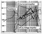
- FIG. 1 shows an example of characteristics of a speaker system prototyped for verification of the present invention described in claim 1.
- the speaker system for the test is a speaker unit with a nominal diameter of 70 mm, a rated power of 15 W, an impedance of 8 ohms, and two resonators with an inner volume of 62.5 cm ⁇ 3, a diaphragm window area of 25 cm ⁇ 2, a weight of 40 g, But,
- the enclosed cabinet is 130mm in width, 94mm in height and 69mm in depth.
- Impedance is the impedance characteristic of the speaker system under test.
- the resonance characteristic of the gradual impedance increase band centered around 120 Hz is gradual. This is due to the fact that the sharp peak near 200Hz, usually called f0, when there is no resonator, couples with the resonance characteristics of the resonator and moves to the lower frequency side. This characteristic is important in the design process for producing good bass reproduction characteristics.
- a power amplifier for sound reproduction is of a voltage output type. This is due to the fact that the characteristics of the speaker are implicitly defined as reproduction characteristics with a constant voltage input. In addition, it has a strong peculiar tone near the bass resonance point called f0.
- the voltage output type power amplifier suppresses this inherent timbre more than the current output type.
- the suppression of resonance-point free vibration is evaluated by a parameter called a damping factor.
- the sound pressure of the current output power amplifier is about 10 dB stronger than that of the voltage output power amplifier. This is equivalent to three times the power difference. The above is known.
- SPL by Voltage Amplifier shows the sound pressure characteristics of a voltage output power amplifier.
- SPL by Current Amplifier shows the sound pressure characteristics of a current output power amplifier. In both characteristics, the level of the input signal is matched so that the SPL matches near 400 Hz at which the impedance shows the minimum value.
- the impedance characteristic of the speaker system In the high frequency range, the impedance characteristic of the speaker system generally increases in proportion to the frequency. In the design process of the speaker unit, it is necessary to satisfy both the bass reproduction characteristics and the treble reproduction characteristics required by the supplier. There is always a cut-and-try task for both factors that have a trade-off relationship. In recent years, as of 2018, in particular, there has been a strong demand for higher performance of small speaker systems, and various attempts have been made to improve the performance of difficult bass reproduction. However, since high-frequency sound reproduction cannot be sacrificed, there is a demand for a method of greatly expanding the degree of freedom in design with a simpler technique. Using a current output power amplifier greatly expands the degree of freedom in design and greatly improves the trade-off between low-frequency sound reproduction performance and high-frequency sound reproduction performance.
- the high-frequency characteristic in FIG. 1 shows the fact.
- the output sound pressure from 3 kHz to 10 kHz is different from that of the voltage output power amplifier in the case of the current output power amplifier because of the impedance characteristic.
- the upper limit of the maximum output voltage is determined by the limitation by the power supply voltage of the power amplifier.
- increasing the power supply voltage of the power amplifier extremely increases the probability of excessive input in a band where the impedance of the voice coil is small. Therefore, when the power supply voltage is increased, the rated output operation in all bands cannot be guaranteed.
- Second, current output power amplifiers are not employed due to the problem of damping factors.
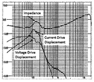
- FIG. 2 shows the difference between the voltage output power amplifier and the current output power amplifier having the vibration amplitude of the voice coil.
- the frequency range of the displacement measuring instrument used to measure this characteristic is from 20 Hz to 500 Hz.
- FIG. 2 shows that the speaker system has a significantly different vibration amplitude in the low frequency range between the current output power amplifier and the voltage output power amplifier.
- These characteristics, including FIG. 1, show that the current output power amplifier is more excellent in both low sound reproduction characteristics and high sound characteristics than the voltage output power amplifier.
- the vibration amplitude increases as the reproduction frequency shifts toward a lower frequency range, there is a limit to softening the damper and the edge in a small speaker system having a narrow dynamic range. This limit is the plateau in the ultra-low sound range of the vibration amplitude in FIG.
- the vibration amplitude of the voice coil can be known, the dynamic range of the low frequency range can be controlled on the signal processing side according to the low sound intensity of the signal, so that the elasticity of the damper can be softened. The above is known.
- the allowable rated power of the speaker system is determined by the guaranteed maximum environmental temperature and the allowable temperature of the voice coil. This depends on the power loss of the voice coil, the heat capacity of the coil and the bobbin, and the heat radiation condition of the bobbin. Further, since the heat radiation condition of the voice coil generally depends on the vibration amplitude of the voice coil, the heat radiation condition is different between the low frequency range and the high frequency range. When the signal is only in the high frequency range, the vibration amplitude of the voice coil becomes extremely small, and as a result, the cooling effect by the airflow near the voice coil is extremely reduced. This must be taken into account depending on the purpose and type of speaker system and the conditions of use. The above is known.
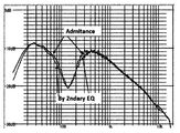
- FIG. 4 shows the respective characteristics of the eight secondary filters necessary for this approximation and the overall characteristics of gain and phase. The adjustment of these filters focuses only on the gain characteristics and ignores the phase characteristics.
- the actual measured value of the pure resistance of the voice coil of the speaker under test in FIGS. 1 and 2 is 6.84 ohms
- the absolute value of the impedance which is the ratio of the measured current value to the measured voltage value with a 440 Hz signal, is 6.6 ohms.
- the difference is 3.5%. That is, the impedance of the speaker system at the minimum point of impedance or the maximum point of admittance is approximately equal to the pure resistance of the voice coil. This proves that the measurement of the pure resistance of the voice coil can be obtained with necessary and sufficient accuracy from the measured values of the supply current and the supply voltage to the speaker system.
- the actual measured value of the impedance of the voice coil at 440 Hz in an environment at room temperature of 26 degrees C is 6.6 ohms.
- the temperature coefficient of resistance shall be 1.0035 / degree.
- a current of 4000 Hz and 0.5 A was applied, and the measured value of the impedance of the voice coil at 440 Hz after 10 minutes was 8.4 ohms. From this, the temperature rise of the voice coil can be estimated to be 78 ° C.
- a current of 80 Hz and 0.5 A was passed, and after 10 minutes, the measured value of the impedance of the voice coil at 440 Hz was 7.1 ohms.
- the temperature rise of the voice coil can be estimated to be 22 ° C. Since the heat loss of both voice coils can be considered to be the same for the same 0.5 A current, it can be concluded that the difference between the two is due to the difference in air flow heat radiation conditions caused by the voice coil vibration. Since the temperature characteristics of the resistance of the voice coil used are known, the temperature rise and temperature of the voice coil can be measured by the method described in claim 2.
- Patent literature is described in the background art.
- Assignment 3 The vibration amplitude of the voice coil in the impedance increase band increases, and the sound output in this band increases.
- this frequency band is driven by an amplifier having a low impedance output, the current flowing through the speaker system decreases as the impedance increases.
- a power amplifier for driving a normal speaker has a low impedance output, and the power supplied to the speaker system in the band where the conversion efficiency is increased decreases in inverse proportion to the change in impedance. That is, in this frequency band, the capability of the speaker system is not used up from the viewpoint of thermal design.
- the impedance of a speaker unit increases as the frequency increases in a high frequency range.
- the main cause is inductance caused by the voice coil. This is a main cause of a decrease in sound output in a high frequency band. This tendency becomes remarkable with the improvement of bass reproduction performance.
- the current consumption of the loudspeaker system under the maximum rated voltage corresponding to the nominal impedance at high frequencies is reduced. As a result, the heat loss generated by the voice coil is reduced. That is, in this frequency band, the capability of the speaker system is not used up from the viewpoint of thermal design.
- the maximum rated output of the power amplifier is designed to balance the maximum rated power of both in operation according to the nominal allowable power of the speaker system. That is, the nominal maximum effective voltage of the low output impedance power amplifier is designed based on the square root of the product of the nominal maximum rated power of the speaker and the nominal impedance. This is implemented without exception when designing a reproduction system in which the speaker system and the power amplifier are integrated.
- the power supply voltage for driving the power amplifier is determined based on a voltage that satisfies the maximum effective voltage. It is customary to never design a power supply voltage that would damage or burn out the speaker system.
- the present invention combines known techniques. Given the operating state of a given sound reproducer, the voltage, current, heat loss, temperature, and vibration amplitude of the voice coil are estimated by calculation and precisely controlled so as not to exceed allowable limits, so that the power amplifier and speaker system have How to get the most out of it.
- Means 1 Measure the resistance value Ra of the voice coil of the speaker system at the ambient temperature Qa.
- Means 2 Measure the impedance or admittance characteristics of the speaker system.
- Means 3 Based on the impedance or admittance characteristics of the speaker system, Determines the output voltage of the voltage output power amplifier that can supply the maximum allowable current to the speaker system in all frequency bands.
- the allowable current is determined based on the allowable power of ⁇ 1 + KRq * ⁇ qmax (t) -Qa ⁇ * Ra * i (t) ⁇ 2.
- Krq is the temperature coefficient of resistance of the voice coil
- qmax (t) is the allowable temperature of the voice coil
- Ra is the pure resistance of the voice coil at the ambient temperature Qa. Since the resistance value of the voice coil fluctuates depending on the temperature of the voice coil, the value is corrected depending on the calculated temperature of the voice coil. For example, in the description of the background art No. 7, when a DC current of 4000 Hz and 0.5 A flows, the resistance of the voice coil increases by 27% with respect to a normal temperature state.
- Means 4 Vmax, Imax, Pmax, Qmax, Dmax, Kvmin, Kvmax, Kvmin, Kimax, Kimin, Kpmax, Kpmin, Determine KRq, Qa, Ra, Kqmax, Kqmin, Kdmax, Kdmin, Tva, Tvr, Tia, Tir, Tpa, Tpr, Tqa, Tqr.
- Means 6 Determine the characteristics H (f) of the sound quality finishing filter to make the reproduction characteristics the expected characteristics.
- Means 9 A calculation function for calculating the voice coil vibration amplitude suppression coefficient LCd ⁇ f, Kd ⁇ is built.
- Effect 1 The potential of the small speaker system can be maximized within the safe area.
- Effect 2 Although it is a calculated value in the aging test process, the voltage, current, power, temperature, and vibration amplitude status of the voice coil can be accurately monitored, thereby improving the objectivity of the reliability design.
- Effect 3 If a problem such as failure or quality occurs during the sale of a product, it can be quickly responded by changing the set values of allowable limits of voltage, current, power, temperature, and vibration amplitude.
- Effect 4 If a problem such as a change in the material or shape occurs during the production of a product, it can be quickly responded by changing the set values of the allowable limits of voltage, current, power, temperature, and vibration amplitude.
- Standardization of the design for obtaining the maximum effect of the reproduction device using the small speaker system 2. Especially, the standardization of the design for obtaining the maximum effect of the reproduction device using the speaker system having the resonator. Shortening the product development process by making the design process of the playback device work part 4. Standardization of reliability design that enables the operator to grasp the operation status of the speaker unit. Part 5. The current temperature of the voice coil, although it is an estimated value by calculation. Can control. Part 6. IP conversion of source code for a series of signal processing programs
- FIG. 1 is an explanatory diagram showing the difference between the impedance characteristics of a speaker system of a test sample and the reproduction characteristics of a voltage output power amplifier and a current output power amplifier. As described in the background art section.
- FIG. 2 is an explanatory diagram of the difference between the impedance characteristics of the speaker system of the test sample and the vibration amplitude frequency characteristics of the voice coil between the voltage output power amplifier and the current output power amplifier. As described in the background art section.
- FIG. 3 is an explanatory diagram of an example in which a given frequency characteristic is approximated by eight secondary filters. As described in the background art section.
- FIG. 4 is an explanatory diagram of the overall gain characteristics and overall phase characteristics of the filter. As described in the background art section.
- FIG. 5 is a block diagram for explaining claim 1 of the present invention.
- s (t) is a playback signal
- Tone Conditioning is a sound quality finishing filter that adjusts the sound quality of the entire playback system
- Intensity Conditioning is a coefficient unit and low-frequency cutoff filter that comprehensively suppresses voltage, current, heat loss, temperature, and vibration amplitude.
- Power Amp is a power amplifier
- Speaker System is a speaker system Seting Parameters are parameters determined by design required for the function of the system of the present invention to function
- Signal Estimation is the instantaneous value of the voice coil's pure resistance, voltage, current, heat loss, temperature, vibration amplitude, etc.
- Intensity Detection is a function that calculates the control variables required to control the allowable limit of each factor based on the calculated values of voltage, current, heat loss, temperature, and vibration amplitude. Formulas and parameters required for control are determined by design.
- the function of suppressing the voltage of the voice coil or the output voltage of the power amplifier is controlled by ⁇ Kv ⁇ so that the amplitude of the voltage falls below the allowable value so that the output of the power amplifier does not saturate.
- the essence of the present invention is not voltage suppression inside the signal processing system but voltage suppression as a part of the operation state of the entire reproduction apparatus.
- the voice coil current or power amplifier output current suppression function is controlled by ⁇ Ki ⁇ so that the current falls below the allowable value.
- the essence of the present invention is not the suppression of the amplitude inside the signal processing system, but the suppression of the current as a part of the operation state of the entire reproducing apparatus.
- Kp is controlled so that the power consumption of the voice coil falls below the allowable value.
- Kq is controlled so that the temperature or temperature rise of the voice coil stays below the allowable value.
- Kd is controlled so that the vibration amplitude of the voice coil falls below the allowable value.
- the suppression of the vibration amplitude of the voice coil does not control the magnitude of the signal, but causes the low-frequency cutoff filter to function and has a large effect on the lower frequency.
- Many songs have strong bass signals recorded. However, in normal listening at a signal level that is not so large, it is desirable to be able to reproduce to the maximum extent possible in the low frequency range. For this reason, it is effective to suppress the vibration amplitude by controlling the cutoff frequency of the bass cutoff filter LCd ⁇ f, Kd ⁇ .
- K (f) Kv * Ki * Kp * Kq * LCd ⁇ f, Kd ⁇ .
- Vmax, Imax, Pmax, Qmax, and Dmax are determined in design based on the permissible limit values of the power amplifier and the speaker system, based on product planning and reliability design policies.
- Kvmin, Kvmax, Kimin, Kimax, Kpmin, Kpmax, Kqmin, Kqmax are It is designed and determined depending on Vmax, Imax, Pmax, Qmax, and Dmax.
- Tva, Tvr, Tia, Tir, Tpa, Tpr, Tda, and Tdr are each determined by design according to the nature of the signal to be suppressed. In general, the time constants of the fast attack time and the slow release time are appropriate for hearing. The following values are guidelines as reference examples of attack time.
- Tva is less than about 10 msec
- intermodulation distortion caused by saturation due to overvoltage is sensitive to hearing.
- Tia is less than about 100msec
- short-time overcurrent is not sensitive to hearing.
- Tpa is less than about 1sec
- the voice coil has heat capacity and short-time overpower is not a problem.
- Tda is about 10msec or less, the over-amplitude of the speaker system is sensitive to hearing as intermodulation distortion.
- Tvr, Tir, Tpr, and Tdr The standard for Tvr, Tir, Tpr, and Tdr is 1.5 to 30 seconds each. It is necessary to minimize the uncomfortable feeling of the gain change, which is a by-product of the suppression function.
- the uncomfortable feeling can be reduced. For example, voltage suppression is set to high speed, and current suppression is set to low speed. Furthermore, by applying two types of high speed and low speed to one suppression function, this uncomfortable feeling can be greatly reduced.
- the detection of the temperature rise q (t) requires a calculation model that includes strictly complicated nonlinearities depending on the heat capacity and heat radiation conditions.
- Jq (f) can model the square root of the intensity of the frequency characteristic of the temperature rise with a combination of first and second order filters.
- Tq (f) is a characteristic under a heat radiation condition having a large thermal time constant.
- the temperature of the voice coil can be calculated by convolution integration with time-varying heat loss using the characteristic of the time lapse of the temperature rise as the integration nucleus of the impulse response characteristic.
- the specific calculation formula is determined by design.
- the calculation of the heat loss of the voice coil which is the reference for temperature rise, uses a calculation model that takes into account the effect of the temperature rise of the voice coil's pure resistance. It can be calculated with sufficient accuracy.
- Int ⁇ v (t) ⁇ , Int ⁇ i (t) ⁇ , Int ⁇ p (t) ⁇ , Int ⁇ d (t) ⁇ are voltage strength, current strength, Heat loss intensity and vibration amplitude intensity.
- the procedure for calculating each strength is determined by design. Since it is necessary to detect the maximum instantaneous value, Use the maximum absolute value of v (t), i (t), p (t), d (t).
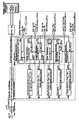
- FIG. 6 is an explanatory diagram of a measuring device having a function of obtaining main parameters of the setting parameters of FIG. 5 by automatic measurement and calculation.
- the voltage detection portion is of a balanced type. An unbalanced type is acceptable as long as it can be measured without errors.
- rs is a current detection resistor having a small resistance value for current detection. By detecting the differential voltage across rs, the current supplied to the voice coil can be measured. If the resistance of the voice coil is 4 ohms, the required value of rs can be 0.1 ohms for the required measurement.
- DS measures the displacement of the voice coil.
- a white noise, an M-sequence random signal, or a signal that sweeps a sine wave is used. Supply this signal to the power amplifier, or supply the measurement signal from the input terminal, It can also be measured by setting H (f) and k (f) to 1 constantly.
- G ⁇ f, q (t) ⁇ is a signal obtained by performing a fast Fourier transform of the voltage signal across the voice coil, It can be obtained by dividing the measurement signal by the signal subjected to the fast Fourier transform.
- Y ⁇ f, KRq, R, q (t) ⁇ is a signal obtained by subjecting the current signal of the voice coil to a fast Fourier transform, It is obtained by dividing the measurement signal by the signal subjected to the fast Fourier transform.
- the phase information is insignificant and can be ignored. Therefore, it is sufficient to calculate only the size.
- the calculation formulas reflecting the effect of the temperature rise q (t) of the voice coil of G ⁇ , Y ⁇ need not be a calculation formula expressed precisely and continuously.
- R is the minimum value Fzmin of ABS ⁇ G (f, q (t)) / Y ⁇ f, q (t) ⁇ . There may be multiple minimum points Fzmin. In this case, Select the minimum value of ABS ⁇ G (f, q (t)) / Y ⁇ f, q (t) ⁇ at the minimum point.
- the normal speaker Fzmin lies between 40Hz and 200Hz.
- D ⁇ f, KRq, R, q (t) ⁇ is a signal obtained by performing a fast Fourier transform of the vibration amplitude of the voice coil, It is obtained by dividing the test signal by the signal subjected to the fast Fourier transform.
- the vibration amplitude of the voice coil is also affected by each component based on the temperature of the voice coil.
- the calculation formula reflecting the effect of the temperature rise q (t) of the voice coil of D ⁇ does not need to be a calculation formula accurately and continuously expressed.
- Jq (f) is the frequency characteristic of the square root of the magnitude of the frequency characteristic of the temperature or the temperature rise value for each sampling frequency when a constant current is applied to the voice coil with the signal of the sampling frequency.
- the reason for the square root is that the power that causes the temperature rise of the voice coil in the subsequent calculation is r (t) * ⁇ i (t) * Jq (f) ⁇ ⁇ 2.
- Jp (f) is not a correction factor for the current, but this simplified calculation can provide sufficient accuracy for practical use.
- Tq (f) is a time constant of temperature rise when a constant current is applied to the voice coil.
- the temperature rise depends on the heat capacity and heat radiation conditions, and is a distributed constant system, and is not necessarily linear. However, even if it is calculated as a linear lumped constant system, no practically inconvenient error occurs.
- FIG. 7 is a block diagram for explaining a system in which the reproduction system is divided into bands. It is explanatory drawing corresponding to Claim 5. An example is shown in which the band is divided by four types of speaker systems, and two types of speaker systems are connected to one system of power amplifier.
- Kv11 * Ki11 * Kp11 * Kq11 * LCd11 ⁇ f, Kd11 ⁇ is Kv, Ki, Kp, Kq, LCd (f, Kd) described in claim 1. Respectively correspond to the voltage, current, heat loss, temperature, and vibration amplitude suppression coefficient of the voice coil.
- Kv11 * Ki11 * Kp11 * Kq11 * LCd11 ⁇ f, Kd11 ⁇ is an output of Intensity-Detection-11, and corresponds to Intensity-Detection of Claim 1.
- the Signal-Detection-11 calculates the pure resistance, voltage, current, heat loss, temperature, and vibration amplitude of the voice coil in accordance with the Intensity-Detection of the first aspect, and calculates the calculated values.
- the input signal of Signal-Detection-11 is s (t) * H (f) * K (f) as in claim 1.
- the parameters determined by the design, which are required by the Intensity-Detection-11 and the Signal-Detection-11, are preliminarily incorporated into the system as in claim 1.
- K12 is a suppression coefficient corresponding to the speaker system 12 of the system 12.
- K2 is a suppression coefficient corresponding to the speaker system 2 of the system 2.
- K3 is a suppression coefficient corresponding to the speaker system 3 of the system 3.
- Intensity-Detection-12, Intensity-Detection-2, and Intensity-Detection-3 are suppression coefficients for each subband
- Signal-Detection-12, Signal-Detection-2, Signal-Detection-3 are detection signals in calculation of each divided band
- Parameter-Set-12, Parameter-Set-2, and Parameter-Set-3 are parameters required for signal detection calculation and strength calculation of each divided band.
- a second aspect of the present invention relates to a method and apparatus for automatic parameter generation that enables simple and accurate setting of complicated parameters described in the first aspect at a design site.
- the temperature of the voice coil greatly changes according to the operating conditions, and as a result, the pure resistance of the voice coil greatly changes.
- the task of knowing the temperature of the voice coil is important for accurately understanding the operating state of the speaker system. To calculate the temperature of the voice coil, it is necessary to know the relationship between the current of the environmental voice coil, the value of the pure resistance of the voice coil, and the thermal time constant. In addition, the influence on the heat radiation condition that depends on the vibration amplitude of the voice coil must be considered.
- the temperature q (t) of the voice coil is estimated by a design formula determined using a parameter group actually measured in advance. Based on the estimated temperature of the voice coil, G ⁇ f ⁇ , Y ⁇ f ⁇ , D ⁇ f ⁇ and the temperature q (t) are also incorporated into the calculation formula and calculated.
- the voltage and current of the voice coil with respect to the input of the power amplifier greatly depend on the pure resistance of the voice coil, the calculation model of G ( ⁇ f ⁇ and Y ⁇ f ⁇ The change in resistance due to coil temperature must be reflected, the temperature of the voice coil required for these formulas is also a calculated value, and a series of results in which the calculated temperature value forms a closed loop.
- the calculation error due to the positive feedback or the negative feedback may further increase due to the calculation error of q (t) because it is included in the calculation of the ambient temperature. Since the function of measuring the temperature rise of the voice coil and the temperature of the voice coil is provided, it is possible to evaluate the error of the entire calculation processing based on claim 1. That is, the temperature estimated by the calculation.
- a third aspect of the present invention relates to a method of determining the specifications of the maximum output voltage of the power amplifier and the impedance of the speaker system in the case of the design of the conventional reproducing apparatus.
- the output voltage of the power amplifier can be greatly increased without being bound by the conventional practice.
- the present invention relates to a technique capable of significantly reducing the impedance of a voice coil.
- the supplementary explanation of claim 4 is based on the fact that a closed loop including itself is formed in the calculation process of r (t) and q (t) described in claim 1 through the calculation of i (t). It relates to the function of suppressing the expansion of calculation errors.
- the present invention relates to an application of claim 1 in a case where a plurality of power amplifiers and speaker systems are provided and divided into bands.
- the filter for band division for each band is integrated with the power amplifier.
- parameter group and voice coil pure resistance, voltage, current, It has a function of calculating signal detection and a function of calculating suppression coefficients for heat loss, temperature, and vibration amplitude.
- the operating state is detected for each speaker system in a state where the power amplifier and each speaker system are combined, and the suppression coefficient is determined based on each allowable value. Is calculated.
- the total suppression coefficient is a product of suppression coefficients calculated for each speaker system.
- the inputs of all the power amplifiers are common, and the common signal is subjected to the sound quality finishing filter and the overall suppression coefficient of the entire reproduction system and supplied to the respective power amplifiers. All operations in the case of band division are based on the operations described in claim 1.
- FIG. Of the speaker system under test, Impedance impedance characteristics SPL by Voltage Amplifier SPL by voltage output power amplifier SPL by Current Amplifier SPL by current output power amplifier
- FIG. Of the speaker system under test, Voltage drive Displacement Vibration of voice coil by voltage drive Current drive Displacement Vibration of voice coil by current drive
- FIG. of the speaker system under test Admitance Admittance characteristics By Secondary EQ Approximation by eight secondary filters
- FIG. The approximation characteristic of FIG. EQ1, Eq2 ,,,,,,, EQ12 12 secondary filters Gain Total gain characteristics of eight secondary filters Pahse Total phase characteristics of eight second-order filters
- FIG. Measurement Equipment Parameter Measurement Tool Displacement Sencer Voice coil vibration amplitude sensor DS vibration amplitude sensor Displacement Vibration amplitude measurement input Test Signal Signal output for measurement Voltage Voltage measurement input Current Current measurement input rs Current detection resistor Dislacement Vibration amplitude measurement input Measurment ⁇ G ⁇ f, q (t) ⁇ , Y ⁇ f, q (t) ⁇ , Ra, Qa, Jq (f), Tq (f), D ⁇ f, q (t) ⁇ Output of measured parameters
- FIG. K11 (f), K12 (f), K2 (f), K3 (f) Band-wise suppression coefficients corresponding to power amplifiers and speakers for each divided band K (f) K11 (f) * K12 (f) * K2 (f) * K3 (f) Overall suppression coefficient Power-Amp-1, Power-Amp-2, Power-Amp-3 Power amplifier with built-in split filter for each split band H1 (f), H2 (f), H3 (f) Split characteristics for each split band PA-1, PA-2, PA-3 Power amplifier for each divided band Speaker-System-11 1st speaker system with split band 1 Speaker-System-12 Second speaker system with split band 1 Speaker-System-2 Split-band 2 speaker system Speaker-System-3 Speaker system with 3 split bands Parameter-set-1, Parameter-set-1, Parameter-set-1 Parameter group for each sub-band Signal-Detection-1, Signal-Detection-2, Signal-Detection-3 Signal detection for each sub-band Intensity-Detection-1, Intensity-Detection-2, Intensity
Landscapes
- Physics & Mathematics (AREA)
- Engineering & Computer Science (AREA)
- Acoustics & Sound (AREA)
- Signal Processing (AREA)
- Circuit For Audible Band Transducer (AREA)
Abstract
Le problème selon la présente invention concerne des systèmes de haut-parleur, qui sont devenus plus petits, susceptibles d'offrir des performances plus élevées, et plus légers, à condition de minimiser le coût et la géométrie, des paramètres se rapportant à des éléments d'évaluation respectifs sont en relation contradictoire les uns avec les autres dans la lumière des performances du système. Bien qu'il soit souhaité d'étendre la liberté de sélection de tous les paramètres, cela n'est pas simple de nos jours lorsqu'un niveau élevé de perfection est déjà atteint. Le marché a en outre des besoins, et afin de satisfaire les besoins, une approche décisive pour étendre fortement le degré de liberté de conception est nécessaire. La solution selon la présente invention concerne diverses capacités de limite dans des systèmes de reproduction acoustique comprenant des systèmes de haut-parleur, dans des fréquences sonores basses et élevées en particulier et dans toutes les bandes généralement, une tension de sortie d'un amplificateur de puissance, un courant électrique fourni à une bobine acoustique, la consommation d'énergie de la bobine acoustique, une température de la bobine acoustique, et une amplitude de vibration de la bobine acoustique sont calculées à partir de paramètres connus requis pour les signaux de calcul et d'entrée, l'état de fonctionnement étant déterminé et un signal de reproduction étant limité à un état dans des limites admissibles.
Applications Claiming Priority (2)
| Application Number | Priority Date | Filing Date | Title |
|---|---|---|---|
| JP2018159746A JP6503537B1 (ja) | 2018-08-07 | 2018-08-07 | スピーカーシステムの限界能力を引き出す制御方法と装置 |
| JP2018-159746 | 2018-08-07 |
Publications (1)
| Publication Number | Publication Date |
|---|---|
| WO2020031394A1 true WO2020031394A1 (fr) | 2020-02-13 |
Family
ID=66324105
Family Applications (1)
| Application Number | Title | Priority Date | Filing Date |
|---|---|---|---|
| PCT/JP2018/033150 Ceased WO2020031394A1 (fr) | 2018-08-07 | 2018-09-07 | Dispositif et procédé de commande destinés à l'exploitation des capacités de limite d'un système de haut-parleur |
Country Status (2)
| Country | Link |
|---|---|
| JP (1) | JP6503537B1 (fr) |
| WO (1) | WO2020031394A1 (fr) |
Cited By (1)
| Publication number | Priority date | Publication date | Assignee | Title |
|---|---|---|---|---|
| WO2024207203A1 (fr) * | 2023-04-04 | 2024-10-10 | 瑞声科技(南京)有限公司 | Procédé de protection thermique de haut-parleur d'aigus pour haut-parleur coaxial, et dispositif associé |
Families Citing this family (1)
| Publication number | Priority date | Publication date | Assignee | Title |
|---|---|---|---|---|
| CN112533115B (zh) * | 2019-09-18 | 2022-03-08 | 华为技术有限公司 | 一种提升扬声器的音质的方法及装置 |
Citations (4)
| Publication number | Priority date | Publication date | Assignee | Title |
|---|---|---|---|---|
| JPS62120195A (ja) * | 1985-11-20 | 1987-06-01 | Matsushita Electric Ind Co Ltd | 低歪スピ−カ装置 |
| JP2005129977A (ja) * | 2003-10-21 | 2005-05-19 | Fyuutorekku:Kk | スピーカユニット |
| JP2015130581A (ja) * | 2014-01-07 | 2015-07-16 | 角元 純一 | 音響再生システム |
| WO2018116861A1 (fr) * | 2016-12-22 | 2018-06-28 | ソニー株式会社 | Dispositif, procédé et programme de traitement de son |
-
2018
- 2018-08-07 JP JP2018159746A patent/JP6503537B1/ja not_active Expired - Fee Related
- 2018-09-07 WO PCT/JP2018/033150 patent/WO2020031394A1/fr not_active Ceased
Patent Citations (4)
| Publication number | Priority date | Publication date | Assignee | Title |
|---|---|---|---|---|
| JPS62120195A (ja) * | 1985-11-20 | 1987-06-01 | Matsushita Electric Ind Co Ltd | 低歪スピ−カ装置 |
| JP2005129977A (ja) * | 2003-10-21 | 2005-05-19 | Fyuutorekku:Kk | スピーカユニット |
| JP2015130581A (ja) * | 2014-01-07 | 2015-07-16 | 角元 純一 | 音響再生システム |
| WO2018116861A1 (fr) * | 2016-12-22 | 2018-06-28 | ソニー株式会社 | Dispositif, procédé et programme de traitement de son |
Cited By (1)
| Publication number | Priority date | Publication date | Assignee | Title |
|---|---|---|---|---|
| WO2024207203A1 (fr) * | 2023-04-04 | 2024-10-10 | 瑞声科技(南京)有限公司 | Procédé de protection thermique de haut-parleur d'aigus pour haut-parleur coaxial, et dispositif associé |
Also Published As
| Publication number | Publication date |
|---|---|
| JP2020025238A (ja) | 2020-02-13 |
| JP6503537B1 (ja) | 2019-04-24 |
Similar Documents
| Publication | Publication Date | Title |
|---|---|---|
| JP7188082B2 (ja) | 音響処理装置および方法、並びにプログラム | |
| TW503668B (en) | Method and device for generating digital filters for equalizing a loudspeaker | |
| CN103634726B (zh) | 一种扬声器自动均衡方法 | |
| US8175284B2 (en) | Method and apparatus for calibrating sound-reproducing equipment | |
| US9578416B2 (en) | Control of a loudspeaker output | |
| US8798280B2 (en) | Calibration method and device in an audio system | |
| US9014397B2 (en) | Signal processing device and signal processing method | |
| JP6182869B2 (ja) | 音声再生装置 | |
| WO2000035247A1 (fr) | Systeme de haut-parleur a commande de retroaction aux fins d'une amelioration de la largeur de bande et d'une diminution de la distorsion | |
| Sturtzer et al. | Comparison between voltage and current driving methods of a micro-speaker | |
| JP2014154956A (ja) | チャンネルデバイダおよびこれを含む音声再生システム、並びに、クロスオーバー周波数を設定する方法 | |
| Rivet | Room modal equalisation with electroacoustic absorbers | |
| Klippel | Distortion analyzer-a new tool for assessing and improving electrodynamic transducer | |
| WO2020031394A1 (fr) | Dispositif et procédé de commande destinés à l'exploitation des capacités de limite d'un système de haut-parleur | |
| KR101606546B1 (ko) | 무선 마이크를 이용한 원격 음향 조율 시스템 및 그 방법 | |
| CN111050251B (zh) | 用于扬声器的倒相箱建模的非线性端口参数 | |
| US20070237343A1 (en) | Sound Enhancement | |
| US10805723B2 (en) | Automatic characterization of perceived transducer distortion | |
| Klippel | Auralization of Signal Distortion in Audio Systems, Part 1: Generic Modeling | |
| JP7735279B2 (ja) | オーディオ信号の特性を変換する方法及び関連する装置 | |
| WO2024207203A1 (fr) | Procédé de protection thermique de haut-parleur d'aigus pour haut-parleur coaxial, et dispositif associé | |
| CN110213708B (zh) | 一种扬声器系统的非线性测量与音质调谐系统 | |
| JP2012100117A (ja) | 音響処理装置及び方法 | |
| Bouchet et al. | Quantifying Loudspeakers' Power Consumption | |
| Farina et al. | Inverse numerical filters for linearisation of loudspeaker’s response |
Legal Events
| Date | Code | Title | Description |
|---|---|---|---|
| 121 | Ep: the epo has been informed by wipo that ep was designated in this application |
Ref document number: 18929149 Country of ref document: EP Kind code of ref document: A1 |
|
| NENP | Non-entry into the national phase |
Ref country code: DE |
|
| 122 | Ep: pct application non-entry in european phase |
Ref document number: 18929149 Country of ref document: EP Kind code of ref document: A1 |