WO2020031418A1 - Tube poreux et procédé de production de tube poreux - Google Patents
Tube poreux et procédé de production de tube poreux Download PDFInfo
- Publication number
- WO2020031418A1 WO2020031418A1 PCT/JP2019/011709 JP2019011709W WO2020031418A1 WO 2020031418 A1 WO2020031418 A1 WO 2020031418A1 JP 2019011709 W JP2019011709 W JP 2019011709W WO 2020031418 A1 WO2020031418 A1 WO 2020031418A1
- Authority
- WO
- WIPO (PCT)
- Prior art keywords
- porous tube
- tubular body
- fibrils
- water pressure
- environment
- Prior art date
- Legal status (The legal status is an assumption and is not a legal conclusion. Google has not performed a legal analysis and makes no representation as to the accuracy of the status listed.)
- Ceased
Links
Images




Classifications
-
- B—PERFORMING OPERATIONS; TRANSPORTING
- B01—PHYSICAL OR CHEMICAL PROCESSES OR APPARATUS IN GENERAL
- B01D—SEPARATION
- B01D39/00—Filtering material for liquid or gaseous fluids
- B01D39/14—Other self-supporting filtering material ; Other filtering material
- B01D39/16—Other self-supporting filtering material ; Other filtering material of organic material, e.g. synthetic fibres
-
- B—PERFORMING OPERATIONS; TRANSPORTING
- B01—PHYSICAL OR CHEMICAL PROCESSES OR APPARATUS IN GENERAL
- B01D—SEPARATION
- B01D71/00—Semi-permeable membranes for separation processes or apparatus characterised by the material; Manufacturing processes specially adapted therefor
- B01D71/06—Organic material
- B01D71/30—Polyalkenyl halides
- B01D71/32—Polyalkenyl halides containing fluorine atoms
- B01D71/36—Polytetrafluoroethylene
-
- B—PERFORMING OPERATIONS; TRANSPORTING
- B29—WORKING OF PLASTICS; WORKING OF SUBSTANCES IN A PLASTIC STATE IN GENERAL
- B29C—SHAPING OR JOINING OF PLASTICS; SHAPING OF MATERIAL IN A PLASTIC STATE, NOT OTHERWISE PROVIDED FOR; AFTER-TREATMENT OF THE SHAPED PRODUCTS, e.g. REPAIRING
- B29C48/00—Extrusion moulding, i.e. expressing the moulding material through a die or nozzle which imparts the desired form; Apparatus therefor
- B29C48/16—Articles comprising two or more components, e.g. co-extruded layers
- B29C48/18—Articles comprising two or more components, e.g. co-extruded layers the components being layers
- B29C48/20—Articles comprising two or more components, e.g. co-extruded layers the components being layers one of the layers being a strip, e.g. a partially embedded strip
-
- B—PERFORMING OPERATIONS; TRANSPORTING
- B29—WORKING OF PLASTICS; WORKING OF SUBSTANCES IN A PLASTIC STATE IN GENERAL
- B29C—SHAPING OR JOINING OF PLASTICS; SHAPING OF MATERIAL IN A PLASTIC STATE, NOT OTHERWISE PROVIDED FOR; AFTER-TREATMENT OF THE SHAPED PRODUCTS, e.g. REPAIRING
- B29C55/00—Shaping by stretching, e.g. drawing through a die; Apparatus therefor
- B29C55/22—Shaping by stretching, e.g. drawing through a die; Apparatus therefor of tubes
-
- B—PERFORMING OPERATIONS; TRANSPORTING
- B29—WORKING OF PLASTICS; WORKING OF SUBSTANCES IN A PLASTIC STATE IN GENERAL
- B29C—SHAPING OR JOINING OF PLASTICS; SHAPING OF MATERIAL IN A PLASTIC STATE, NOT OTHERWISE PROVIDED FOR; AFTER-TREATMENT OF THE SHAPED PRODUCTS, e.g. REPAIRING
- B29C67/00—Shaping techniques not covered by groups B29C39/00 - B29C65/00, B29C70/00 or B29C73/00
- B29C67/20—Shaping techniques not covered by groups B29C39/00 - B29C65/00, B29C70/00 or B29C73/00 for porous or cellular articles, e.g. of foam plastics, coarse-pored
-
- C—CHEMISTRY; METALLURGY
- C08—ORGANIC MACROMOLECULAR COMPOUNDS; THEIR PREPARATION OR CHEMICAL WORKING-UP; COMPOSITIONS BASED THEREON
- C08J—WORKING-UP; GENERAL PROCESSES OF COMPOUNDING; AFTER-TREATMENT NOT COVERED BY SUBCLASSES C08B, C08C, C08F, C08G or C08H
- C08J9/00—Working-up of macromolecular substances to porous or cellular articles or materials; After-treatment thereof
Definitions
- the present disclosure relates to a porous tube and a method for manufacturing a porous tube.
- This application claims the priority based on Japanese Patent Application No. 2018-150113 filed on Aug. 9, 2018, and incorporates all the contents described in the Japanese application.
- porous filters are widely used in industrial facilities, vehicles, fuel cells, and the like.
- This porous filter is required to be able to maintain a constant quality over a long period of time in a use environment.
- this porous filter when used in an incinerator, a drying oven, a clean room, or the like, it is required to have high heat resistance according to the use environment, and when attached to an automobile, it can withstand exhaust gas, engine heat, and the like. High heat resistance is required.
- a filter for treating exhaust gas from an incinerator is exemplified.
- This filter is required to have high heat resistance that can cope with exhaust gas. From such a point, a filter provided with a heat-resistant base material containing polytetrafluoroethylene as a main component has been proposed as a filter today (see JP-A-2002-11312).
- porous filter attached to an automobile examples include, for example, an air filter disposed near an ECU (Electronic Control Unit), an air filter for a headlight, an air filter for a gas sensor, and the like.
- ECU Electronic Control Unit
- a gas sensor for measuring the concentration of oxygen contained in exhaust gas of automobiles and the like can be mentioned.
- This gas sensor has a gas introduction part for introducing an external gas, and the gas introduction part is provided with a porous filter having gas permeability.
- This porous filter is required to have high heat resistance to cope with automobile exhaust gas in addition to gas permeability. Therefore, a porous body containing polytetrafluoroethylene as a main component has been proposed as a porous filter today (see Japanese Patent Application Laid-Open No. 2008-216049).
- the porous tube according to one embodiment of the present disclosure has a fibrous skeleton containing polytetrafluoroethylene as a main component, and has a water resistance P1 after holding for 3 hours in an environment of 300 ° C. and G1 Gurley seconds.
- P2 water resistance after holding for 3 hours in an environment of 360 ° C.
- the Gurley seconds are G2
- the following expressions (1) and (2) are satisfied.
- a method for manufacturing a porous tube includes a step of forming a tubular body by extruding a cylindrical compression-molded body of powder containing polytetrafluoroethylene as a main component; A step of stretching in the longitudinal direction while heating the, and a step of firing the tubular body after the stretching step while maintaining the length, and a step of firing the porous tube, after the firing step
- the method further includes a step of shrinking the tubular body in the length direction while heating the tubular body.
- FIG. 1 is a schematic perspective view showing a porous tube according to an embodiment of the present disclosure.
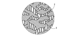
- FIG. 2 is a schematic enlarged view showing a fibrous skeleton of the porous tube of FIG.
- FIG. 3 is a flowchart illustrating a method for manufacturing a porous tube according to an embodiment of the present disclosure.
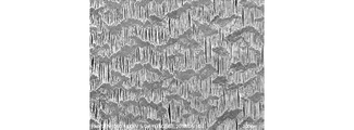
- FIG. 4 is an SEM image showing a fibrous skeleton of a porous tube of No. 1.
- FIG. 3 is an SEM image showing a fibrous skeleton of a porous tube of No. 3.
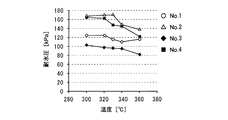
- FIG. 1 to No. 4 is a graph showing the water pressure resistance of the porous tube of Example 4 after the heat resistance test.
- FIG. 1 to No. 4 is a graph showing Gurley seconds after a heat resistance test of porous tube No. 4.
- the filter (heat-resistant substrate) of Patent Literature 1 and the porous body of Patent Literature 2 are excellent in heat resistance because they contain polytetrafluoroethylene as a main component.
- gas sensors for automobiles may be exposed to water due to the usage environment such as weather. Therefore, it is desired that the porous filter used in the gas sensor has excellent water pressure resistance.
- conventional porous filters as described in Patent Literature 1 and Patent Literature 2 have lower water pressure resistance as they are used.
- gas sensors for automobiles are sometimes heated by exhaust gas and exposed to a high temperature exceeding 327 ° C., which is the melting point of PTFE, for a relatively long time. It is difficult to maintain sufficient water pressure resistance when used.
- the present disclosure has been made based on such circumstances, and has as its object to provide a porous tube having excellent heat resistance and capable of sufficiently maintaining water pressure resistance. Another object of the present disclosure is to provide a method for manufacturing a porous tube that is excellent in heat resistance and can sufficiently maintain water pressure resistance.
- a porous tube that is excellent in heat resistance and sufficiently maintains water pressure and a porous tube that is excellent in heat resistance and capable of producing a porous tube capable of sufficiently maintaining water pressure.
- a manufacturing method can be provided.
- the porous tube according to one embodiment of the present disclosure has a fibrous skeleton containing polytetrafluoroethylene as a main component, and has a water resistance P1 after holding for 3 hours in an environment of 300 ° C. and G1 Gurley seconds.
- P2 water resistance after holding for 3 hours in an environment of 360 ° C.
- G1 Gurley seconds are G2
- the following expressions (1) and (2) are satisfied.
- the porous tube has a fibrous skeleton containing polytetrafluoroethylene as a main component, and is excellent in heat resistance. Further, since the porous tube satisfies both the above formulas (1) and (2), even when exposed to a high-temperature environment, it is possible to sufficiently maintain the water resistance while maintaining the air permeability.
- the porous tube may further satisfy the following formula (3) in addition to the above formulas (1) and (2).
- the above formula (3) is considered to be satisfied when the porous tube is kept in a high-temperature environment of 360 ° C. for 3 hours so that the diameter of the fibrous skeleton is suppressed. Therefore, by satisfying the above expression (3), it is possible to suppress a decrease in water pressure resistance due to the reduction in the diameter of the fibrous skeleton.
- the porous tube preferably has a length change rate of 5% or less before and after being kept at 280 ° C for 1 hour. As described above, since the rate of change in length before and after holding for 1 hour in an environment of 280 ° C. is equal to or less than the upper limit, deterioration in quality and increase in replacement frequency due to change in length can be suppressed. it can.
- the fibrous skeleton has a plurality of nodes and a plurality of fibrils connecting the plurality of nodes, and the plurality of fibrils have slack.
- the fibrous skeleton has a plurality of nodes and a plurality of fibrils connecting the plurality of nodes, and the plurality of fibrils have a slack, so that the fibrous skeleton is exposed to a high-temperature environment. It is possible to suppress the reduction in the diameter of the plurality of fibrils and to more reliably suppress the decrease in the water resistance.
- a method for manufacturing a porous tube includes a step of forming a tubular body by extruding a cylindrical compression-molded body of powder containing polytetrafluoroethylene as a main component; A step of stretching in the longitudinal direction while heating the, and a step of firing the tubular body after the stretching step while maintaining the length, and a step of firing the porous tube, after the firing step
- the method further includes a step of shrinking the tubular body in the length direction while heating the tubular body.
- the method for manufacturing the porous tube includes a step of shrinking in a length direction while heating the tubular body after the firing step, the porous tube is excellent in heat resistance and capable of sufficiently maintaining water pressure. Can be manufactured.
- the heating temperature of the tubular body in the shrinking step is preferably from 280 ° C to 330 ° C. In this way, by setting the heating temperature of the tubular body in the shrinking step within the above range, it is possible to easily and reliably suppress a decrease in the water pressure resistance of the porous tube when exposed to a high temperature environment. it can.
- the tubular body can be easily and reliably shrunk in the longitudinal direction, and is exposed to a high-temperature environment. In this case, a decrease in the water resistance of the porous tube can be easily and reliably suppressed.
- the ratio of the shrinkage ratio in the shrinking step to the stretching ratio in the stretching step is preferably 0.03 or more and 0.15 or less. As described above, the ratio of the shrinkage ratio in the shrinking step to the stretching ratio in the stretching step is within the above range, thereby easily and easily reducing the water pressure resistance of the porous tube when exposed to a high-temperature environment. It can be suppressed reliably.
- main component refers to a component having the largest content ratio in terms of mass, for example, a component having a content ratio of 50% by mass or more.
- Hydrofluic pressure refers to a value measured according to the water resistance test B method (high water pressure method) of JIS-L1092: 2009.
- the “Gurley second” is a time measured according to JIS-P8117: 2009, and refers to a time when 100 cm 3 of air passes through a 6.45 cm 2 sample at an average pressure difference of 1.22 kPa.
- Leength change rate refers to a value [%] calculated by the following equation (4).
- C in the equation (4) is a change rate of the length of the porous tube
- Lb is a length before the change
- La is a length after the change.
- C [%] (
- the porous tube 1 shown in FIG. 1 has a fibrous skeleton containing polytetrafluoroethylene (PTFE) as a main component, and has a water resistance P1 after holding at 300 ° C. for 3 hours and a Gurley second G1.
- P2 polytetrafluoroethylene
- the Gurley seconds are G2
- the following expressions (1) and (2) are satisfied.
- the porous tube 1 has a fibrous skeleton containing PTFE as a main component, and is excellent in heat resistance.
- the porous tube 1 satisfies both the expressions (1) and (2), even when exposed to a high-temperature environment, it is possible to sufficiently maintain the water resistance while maintaining the air permeability. More specifically, when a conventional porous tube containing PTFE as a main component is exposed to a high-temperature environment, the fibrous skeleton is partially melted, so that the fiber diameter becomes small and the water pressure resistance decreases. At the same time, in this conventional porous tube, Gurley seconds are reduced as the fiber diameter is reduced. That is, in the conventional porous tube, there is a trade-off relationship between the water resistance and the air permeability.
- the porous tube 1 can simultaneously suppress a decrease in water pressure resistance and a decrease in Gurley seconds by suppressing the fiber diameter from decreasing in a high-temperature environment, as described later. Therefore, even when the porous tube 1 is exposed to a high temperature environment, it is possible to sufficiently maintain the water pressure resistance while maintaining the air permeability.
- the upper limit of P1 / P2 is obtained. Is preferably 1.2. If P1 / P2 exceeds the above upper limit, it may be difficult to maintain sufficient water pressure resistance when exposed to a high temperature environment.
- the lower limit of P1 / P2 is preferably 1.0. If P1 / P2 is less than the above lower limit, the production of the porous tube 1 may not be easy.
- the porous tube 1 further satisfies the following formula (3) in addition to the above formulas (1) and (2).
- the above formula (3) is considered to be satisfied when the porous tube 1 is held in a high-temperature environment of 360 ° C. for 3 hours, whereby the reduction in the diameter of the fibrous skeleton is suppressed. Therefore, when the porous tube 1 satisfies the above expression (3), it is possible to sufficiently suppress a decrease in the water pressure resistance due to the reduction in the diameter of the fibrous skeleton.
- the lower limit of the water pressure resistance P1 after maintaining the porous tube 1 in an environment of 300 ° C. for 3 hours is preferably 100 kPa, more preferably 120 kPa. If P1 is less than the above lower limit, there is a possibility that the water pressure resistance becomes insufficient when used in an environment where water is applied, such as an air filter for a vehicle.
- the upper limit of P1 is not particularly limited, but may be, for example, 200 kPa. When P1 exceeds the above upper limit, the production of the porous tube 1 may not be easy, or the air permeability of the porous tube 1 may be insufficient.
- the upper limit of the Gurley second G1 after maintaining the porous tube 1 in an environment of 300 ° C. for 3 hours is preferably 140 seconds, and more preferably 120 seconds. If G1 exceeds the above upper limit, the air permeability of the porous tube 1 may be insufficient. On the other hand, the lower limit of G1 is preferably 20 seconds, and more preferably 40 seconds. If G1 is less than the above lower limit, the pore diameter of the porous tube 1 may be too large and the water pressure may be insufficient.
- the upper limit of the rate of change of the length of the porous tube 1 before and after holding for 1 hour in an environment of 280 ° C. is preferably 5%, more preferably 4%, and still more preferably 2%.
- the porous tube 1 can suppress the lengthwise contraction in a high-temperature environment by suppressing the fiber diameter from decreasing in a high-temperature environment, and can suppress the rate of change to the upper limit or less. If the rate of change exceeds the upper limit, the quality may deteriorate when exposed to high temperatures. Further, when the rate of change exceeds the upper limit, the length of change in length when exposed to a high temperature becomes large, which may make it difficult to arrange the filter at a desired site for a long period of time. When fixed at both ends in the direction, the stress applied to the fixed portion increases, and the fibers may break, which may cause water leakage or the like.
- the lower limit of the rate of change is not particularly limited and can be 0%.
- the porous tube 1 is a single-layer body mainly composed of PTFE.
- the porous tube 1 contains PTFE as a main component, and has excellent heat resistance, chemical stability, weather resistance, nonflammability, strength, and the like.
- the fibrous skeleton has a plurality of nodes 2 (particle masses) and a plurality of fibrils 3 (fibrous portions) connecting the plurality of nodes 2. .
- the plurality of fibrils 3 are oriented in the axial direction of the porous tube 1.
- voids are formed between the fibrils 3 or between the nodes 2 and the fibrils 3.
- the plurality of fibrils 3 have slack.
- the plurality of fibrils 3 can be loosened by being temporarily fixed and then contracted by heating.
- a porous tube is exposed to a high-temperature environment and a part of the resin constituting the fibril is melted, if a plurality of fibrils are strained, the molten resin is pulled toward a node connected to the fibril.
- the plurality of fibrils 3 are loose in the porous tube 1, the resin constituting the plurality of fibrils 3 is absorbed in the fibrils 3, and the diameter of the fibrils 3 is hardly reduced. Therefore, even when the porous tube 1 is exposed to a high-temperature environment, the plurality of fibrils 3 can be suppressed from being reduced in diameter, and a decrease in water resistance can be reliably suppressed.
- the plurality of fibrils 3 are once fixed in a tensioned state and then contracted by heating, so that the fibers that have been elongated in the length direction are contracted and the fiber diameter is increased. Therefore, even when the porous tube 1 is exposed to a high-temperature environment, the fiber diameters of the plurality of fibrils 3 are easily maintained appropriately. Therefore, even when the porous tube 1 is exposed to a high-temperature environment, a decrease in water pressure resistance can be suppressed more reliably.
- At least a part of the fibrils 3 preferably has a bent portion. In other words, it is preferable that at least a part of the fibrils 3 is bent at least partly in the length direction. In the porous tube, since at least a part of the fibrils 3 has a bent portion, it is easy to maintain water permeability by securing a pore area between the fibrils 3 while sufficiently maintaining a water pressure resistance.
- the average fiber diameter of the plurality of fibrils 3 after holding the porous tube 1 under the environment of 360 ° C. for 3 hours is D2, and the average fiber diameter of the plurality of fibrils 3 before holding the porous tube 1 under the environment of 360 ° C. for 3 hours.
- D1 it is preferable that the following formula (5) is satisfied. 0.8 ⁇ D2 / D1 ⁇ 1.1 (5)
- the upper limit of D2 / D1 is more preferably 1.0.
- D2 / D1 is less than the above lower limit, the water pressure may be insufficient due to the reduction in the diameter of the plurality of fibrils 3.
- D2 / D1 exceeds the above upper limit, the production of the porous tube 1 may not be easy.
- the “average fiber diameter” refers to the average diameter of ten fibrils arbitrarily extracted.
- the lower limit of the PTFE content in the porous tube 1 is preferably 90% by mass, more preferably 95% by mass, and even more preferably 98% by mass. If the content of PTFE is less than the above lower limit, the heat resistance of the porous tube 1 may be insufficient.
- the above-mentioned PTFE may include a polymerized unit derived from another copolymerizable monomer as long as the effects of the present disclosure are not impaired.
- the PTFE may include a polymerized unit of perfluoro (alkyl vinyl ether), hexafluoropropylene, (perfluoroalkyl) ethylene, chlorotrifluoroethylene, or the like.
- the upper limit of the content ratio of the polymer units derived from the other copolymerizable monomer is, for example, 3 mol% with respect to all the polymer units constituting PTFE.
- the porous tube 1 may contain another fluororesin, another optional component, or the like as long as the effects of the present disclosure are not impaired.
- the other fluororesins include, for example, tetrafluoroethylene-perfluoroalkylvinyl ether copolymer (PFA), tetrafluoroethylene-hexafluoropropylene copolymer (FEP), polyvinylidene fluoride (PVDF), and tetrafluoroethylene- Ethylene copolymer (ETFE), polychlorotrifluoroethylene (PCTFE), chlorotrifluoroethylene-ethylene copolymer (ECTFE), polyvinyl fluoride (PVF), fluoroolefin-vinyl ether copolymer, vinylidene fluoride-tetra Examples thereof include a fluoroethylene copolymer and a vinylidene fluoride-hexafluoropropylene copolymer.
- the porous tube 1 has a substantially uniform thickness.
- the lower limit of the average thickness of the porous tube 1 can be set according to the application.
- the lower limit can be 0.2 mm or more and 3.0 mm or less.
- the lower limit of the porosity of the porous tube 1 is preferably 30% by volume, and more preferably 40% by volume.
- the upper limit of the porosity of the porous tube 1 is preferably 90% by volume, and more preferably 70% by volume. If the porosity is less than the lower limit, the air permeability may be insufficient. Conversely, if the porosity exceeds the upper limit, the water pressure may be insufficient.
- the “porosity” refers to the ratio of the total volume of pores to the volume, and can be determined by measuring the density of the support layer according to ASTM-D-792.
- the method for manufacturing the porous tube includes a step of forming a tubular body by extrusion molding of a cylindrical compression-molded body of a powder containing PTFE as a main component, and a step of stretching the tubular body in a length direction while heating the tubular body. And baking the tubular body after the stretching step while maintaining the length.
- the method for producing a porous tube further includes a step of shrinking in a length direction while heating the tubular body after the step of baking.
- a plurality of fibrils 3 mainly composed of PTFE are temporarily fixed in a tensioned state in the baking step, and then the fibrils 3 are contracted and relaxed in the contracting step. Things.
- the plurality of fibrils 3 can be given slack by fixing the plurality of fibrils 3 in a tension state and then contracting by heating.
- the obtained porous tube 1 is exposed to a high-temperature environment by loosening the plurality of fibrils 3, even when a part of the resin constituting the plurality of fibrils 3 is melted. These resins can be absorbed in the fibrils 3 and the diameter of the plurality of fibrils 3 can be suppressed. Further, according to the method for manufacturing the porous tube, the fiber diameter of the plurality of fibrils 3 is relatively large, so that even when the obtained porous tube 1 is exposed to a high-temperature environment, the fiber diameter of the plurality of fibrils 3 is large. Is moderately easy to maintain. Therefore, the method for producing a porous tube can produce a porous tube having excellent heat resistance and sufficient water pressure resistance.
- a material obtained by compression molding a raw material in which a liquid lubricant is mixed with a powder mainly composed of PTFE can be used.
- various lubricants conventionally used in the paste extrusion method can be used, for example, naphtha, petroleum solvents such as white oil, hydrocarbon oils such as undecane, toluene, xylol Aromatic hydrocarbons, alcohols, ketones, esters, silicone oils, fluorochlorocarbon oils, solutions of polymers such as polyisobutylene and polyisoprene in these solvents, mixtures of two or more of these, surface activity Water or aqueous solution containing the agent.
- the cylindrical compression molded body is extruded by an extruder equipped with a die having a circular opening and a core pin arranged at the center of the opening of the die to form a tube-shaped body.
- This extrusion is performed at a temperature lower than the melting point of PTFE, and is generally performed at room temperature.
- the tubular body in the forming step, it is preferable to heat the tubular body extruded from the die to volatilize the liquid lubricant.
- the tubular body can be more stably stretched in the next stretching step.
- Step of stretching In the stretching step, the tubular body formed in the forming step is stretched in the length direction while heating.
- the stretching step can be performed by winding the tubular body extruded from the die at a speed higher than the speed extruded from the die while heating.
- the liquid lubricant in the tubular body can be volatilized, and the tubular body can be made porous.
- the lower limit of the stretching ratio of the tubular body in the stretching step is preferably 50%, more preferably 100%.
- the upper limit of the stretching ratio is preferably 400%, more preferably 300%. If the stretching ratio is less than the lower limit, there is a possibility that a sufficient ventilation rate cannot be obtained. If the stretching ratio is less than the lower limit, the shrinkage ratio cannot be sufficiently increased in the shrinking step described below, and the water resistance of the resulting porous tube 1 may be insufficient. Conversely, if the stretching ratio exceeds the upper limit, the tubular body may be broken.
- the lower limit of the heating temperature in the stretching step is preferably 200 ° C., more preferably 220 ° C.
- the upper limit of the heating temperature in the stretching step is preferably 350 ° C, more preferably 300 ° C. If the heating temperature is lower than the lower limit, the pore diameter of the obtained porous tube 1 becomes too large, and the water resistance of the porous tube 1 may be insufficient. On the other hand, when the heating temperature exceeds the upper limit, it is difficult to sufficiently increase the pore size of the porous tube 1 and the air permeability of the porous tube 1 may be insufficient.
- the tubular body after the stretching step is heated to a temperature equal to or higher than the melting point of PTFE while maintaining the length, and fixed in a stretched state.
- the heating temperature in the firing step can be, for example, 350 ° C. or more and 550 ° C. or less.
- the heating time in the baking step can be, for example, 10 seconds or more and 20 minutes or less.
- shrinking process In the shrinking step, the tubular body to which the plurality of fibrils 3 are fixed in a tensioned state by the firing step is thermally shrunk in the length direction.
- the plurality of fibrils 3 are slackened by the shrinking step.
- the plurality of fibrils 3 fixed in the extended state are contracted by the contracting step, and the fiber diameter of these fibrils 3 is increased. Further, in the contracting step, it is also preferable to form a bent portion in at least a part of the fibrils 3.
- the lower limit of the heating temperature of the tubular body in the shrinking step is preferably 280 ° C, more preferably 300 ° C.
- the upper limit of the heating temperature is preferably 330 ° C, more preferably 320 ° C. If the heating temperature is less than the lower limit, the shrinkage of the tubular body becomes insufficient, and the water pressure of the obtained porous tube 1 in a high-temperature environment may become insufficient, or the required heating time Is too long, which may lead to an increase in the size of the manufacturing equipment and a decrease in the manufacturing efficiency. Conversely, when the heating temperature exceeds the upper limit, the heat shrinkage in the shrinking step becomes too large, and the resulting porous tube 1 may have insufficient air permeability.
- the upper limit of the heating time is preferably 30 minutes, and more preferably 20 minutes. If the heating time is less than the above lower limit, the shrinkage of the tubular body becomes insufficient, and the water pressure of the obtained porous tube 1 in a high-temperature environment may be insufficient. If the heating time is less than the lower limit, the required heating temperature becomes too high, and it may be difficult to control the shrinkage. Conversely, if the heating time exceeds the upper limit, the heat shrinkage rate in the shrinking step becomes too large, and the resulting porous tube 1 may have insufficient air permeability. In addition, when the heating time exceeds the upper limit, the production equipment may be increased in size or the production efficiency may be reduced.
- the shrinking step it is preferable to adjust the shrinkage rate according to the degree of elongation of the plurality of fibrils 3 elongated in the stretching step.
- the lower limit of the ratio of the shrinkage ratio in the shrinking step to the stretching ratio in the stretching step is preferably 0.03, and more preferably 0.07.
- the upper limit of the ratio is preferably 0.15, and more preferably 0.12. If the above ratio is less than the above lower limit, loosening of the plurality of fibrils 3 may be insufficient, and it may be difficult to sufficiently maintain the water resistance of the porous tube 1 obtained when exposed to a high temperature environment. Conversely, if the ratio exceeds the upper limit, the shrinkage may become unnecessarily large and the production cost may increase, or the porosity of the obtained porous tube 1 may decrease and the air permeability may become insufficient. There is.
- the step of shrinking it is preferable not to apply tension in the longitudinal direction of the tubular body.
- the plurality of fibrils 3 elongated in the length direction in the stretching step are easily loosened.
- a decrease in the water resistance of the porous tube 1 when exposed to a high-temperature environment can be easily and reliably suppressed.
- the tubular body after the above-described shrinking step constitutes the porous tube 1.
- the method for manufacturing a porous tube may further include a step of cutting the tubular body into a desired size after the contracting step.
- the method of manufacturing the porous tube from the viewpoint of shrinking the tubular body in the length direction, it is preferable that no tension is applied in the longitudinal direction of the tubular body in the shrinking step.
- the shrinking step it is also possible to apply a constant tension in the longitudinal direction of the tubular body from the viewpoint of controlling the shrinkage rate of the tubular body.
- a tubular body is formed by extruding a cylindrical compression-molded body of a powder containing PTFE as a main component (forming step), and the tubular body is heated at 230 ° C., heated for 3 minutes, and stretched at a stretching ratio of 270%.
- the tubular body after stretching was fired at a heating temperature of 430 ° C. for a heating time of 5 minutes while maintaining the length (firing step).
- the water pressure resistance of the fired tubular body was 100 kPa, and the Gurley second was 70 seconds.
- the water pressure was applied from the inside of the tubular body at a rate of 100 kPa per minute, based on the water resistance test B method (high water pressure method) of JIS-L1092: 2009, and the water pressure was applied to the outside. It was determined by the pressure of the leaked water. Gurley seconds were measured in accordance with JIS-P8117: 2009, based on the time required for 100 cm 3 of air to pass through a 6.45 cm 2 sample (tubular body) at an average pressure difference of 1.22 kPa.
- FIG. 4 shows an SEM image of the inner peripheral surface side of the porous tube No. 1.
- FIG. 6 shows the measurement results.
- Table 1 shows the water pressure P1 after holding for 3 hours in a 300 ° C. environment and the water pressure P2 after holding for 3 hours in a 360 ° C. environment.
- the ratio of the water pressure P1 after holding at 300 ° C. for 3 hours to the water pressure P2 after holding at 360 ° C. for 3 hours is 0.9 or more and 1.3 or less, and at 360 ° C.
- the ratio of the Gurley seconds G1 after holding at 300 ° C. for 3 hours to the Gurley seconds G2 after holding for 3 hours is 0.7 or more and 1.1 or less.
- No. 1 and No. 1 The porous tube 2 has a sufficient water pressure resistance even when exposed to a high temperature environment. It is considered that this is because the plurality of fibrils temporarily fixed in the stretched state are loosened and the fiber diameters of these fibrils are expanded by the above-described contracting step.
Landscapes
- Chemical & Material Sciences (AREA)
- Engineering & Computer Science (AREA)
- Chemical Kinetics & Catalysis (AREA)
- Mechanical Engineering (AREA)
- Materials Engineering (AREA)
- Health & Medical Sciences (AREA)
- Medicinal Chemistry (AREA)
- Polymers & Plastics (AREA)
- Organic Chemistry (AREA)
- Manufacture Of Porous Articles, And Recovery And Treatment Of Waste Products (AREA)
Abstract
Le tube poreux selon un mode de la présente invention a un échafaudage fibreux ayant du polytétrafluoroéthylène en tant que composant principal, et satisfait aux formules (1) et (2), lorsque G1 est des secondes Gurley, P1 est la résistance à la pression de l'eau après avoir été maintenue pendant 3 heures dans un environnement de 300 °C, G2 est des secondes Gurley, P2 est la résistance à la pression de l'eau après avoir été maintenue pendant 3 heures dans un environnement à 360 °C. (1) 0,9 ≤ P1/P2 ≤ 1,3 (2) 0,7 ≤ G1/G2 ≤ 1,1
Applications Claiming Priority (2)
| Application Number | Priority Date | Filing Date | Title |
|---|---|---|---|
| JP2018-150113 | 2018-08-09 | ||
| JP2018150113 | 2018-08-09 |
Publications (1)
| Publication Number | Publication Date |
|---|---|
| WO2020031418A1 true WO2020031418A1 (fr) | 2020-02-13 |
Family
ID=69414711
Family Applications (1)
| Application Number | Title | Priority Date | Filing Date |
|---|---|---|---|
| PCT/JP2019/011709 Ceased WO2020031418A1 (fr) | 2018-08-09 | 2019-03-20 | Tube poreux et procédé de production de tube poreux |
Country Status (1)
| Country | Link |
|---|---|
| WO (1) | WO2020031418A1 (fr) |
Citations (7)
| Publication number | Priority date | Publication date | Assignee | Title |
|---|---|---|---|---|
| JPH06106037A (ja) * | 1992-09-25 | 1994-04-19 | Sumitomo Electric Ind Ltd | チューブ状多孔質複層膜及びその製造方法 |
| JPH06246142A (ja) * | 1993-02-19 | 1994-09-06 | Sumitomo Electric Ind Ltd | 管状四弗化エチレン樹脂多孔質体とその製造方法 |
| JPH06256549A (ja) * | 1993-03-02 | 1994-09-13 | Nitto Denko Corp | ポリテトラフルオロエチレン多孔質膜およびその製造法 |
| JPH09241412A (ja) * | 1996-03-07 | 1997-09-16 | Sumitomo Electric Ind Ltd | 延伸ポリテトラフルオロエチレンチューブとその製造方法 |
| JPH10323923A (ja) * | 1997-05-26 | 1998-12-08 | Nitto Denko Corp | ポリテトラフルオロエチレン多孔質チューブ及びその製造方法 |
| JP2001011224A (ja) * | 1999-06-29 | 2001-01-16 | Nitto Denko Corp | 多孔質チューブの製造方法及び多孔質チューブの使用方法 |
| JP2017528346A (ja) * | 2014-09-12 | 2017-09-28 | ダブリュ.エル.ゴア アンド アソシエイツ,インコーポレイティドW.L. Gore & Associates, Incorporated | 改良された機械及び熱特性を有する多孔性通気性ポリテトラフルオロエチレン複合材 |
-
2019
- 2019-03-20 WO PCT/JP2019/011709 patent/WO2020031418A1/fr not_active Ceased
Patent Citations (7)
| Publication number | Priority date | Publication date | Assignee | Title |
|---|---|---|---|---|
| JPH06106037A (ja) * | 1992-09-25 | 1994-04-19 | Sumitomo Electric Ind Ltd | チューブ状多孔質複層膜及びその製造方法 |
| JPH06246142A (ja) * | 1993-02-19 | 1994-09-06 | Sumitomo Electric Ind Ltd | 管状四弗化エチレン樹脂多孔質体とその製造方法 |
| JPH06256549A (ja) * | 1993-03-02 | 1994-09-13 | Nitto Denko Corp | ポリテトラフルオロエチレン多孔質膜およびその製造法 |
| JPH09241412A (ja) * | 1996-03-07 | 1997-09-16 | Sumitomo Electric Ind Ltd | 延伸ポリテトラフルオロエチレンチューブとその製造方法 |
| JPH10323923A (ja) * | 1997-05-26 | 1998-12-08 | Nitto Denko Corp | ポリテトラフルオロエチレン多孔質チューブ及びその製造方法 |
| JP2001011224A (ja) * | 1999-06-29 | 2001-01-16 | Nitto Denko Corp | 多孔質チューブの製造方法及び多孔質チューブの使用方法 |
| JP2017528346A (ja) * | 2014-09-12 | 2017-09-28 | ダブリュ.エル.ゴア アンド アソシエイツ,インコーポレイティドW.L. Gore & Associates, Incorporated | 改良された機械及び熱特性を有する多孔性通気性ポリテトラフルオロエチレン複合材 |
Similar Documents
| Publication | Publication Date | Title |
|---|---|---|
| KR101918204B1 (ko) | 폴리테트라플루오로에틸렌 다공질막 및 에어 필터 여과재 | |
| TWI584871B (zh) | Polytetrafluoroethylene porous membrane and waterproof ventilation components | |
| KR101599111B1 (ko) | Ptfe 중공사막 및 그 제조 방법 | |
| TWI706977B (zh) | 用於製備多孔氟基樹脂膜的方法及多孔氟基樹脂膜 | |
| KR20140056233A (ko) | 폴리테트라플루오로에틸렌 다공질막의 제조 방법 | |
| WO2015182538A1 (fr) | Filtre poreux | |
| CN111050890A (zh) | 氟树脂多孔膜及其制备方法 | |
| JP2001011224A (ja) | 多孔質チューブの製造方法及び多孔質チューブの使用方法 | |
| JP4827372B2 (ja) | ポリテトラフルオロエチレン系樹脂製チューブ及びその製造方法 | |
| TW201718072A (zh) | 被賦予撥油性之通氣過濾器 | |
| CN112672814B (zh) | 中空纤维膜 | |
| CN111655358B (zh) | 基于氟的树脂多孔膜及其制备方法 | |
| WO2020031418A1 (fr) | Tube poreux et procédé de production de tube poreux | |
| KR102729761B1 (ko) | 불소계 수지 다공성 막 및 이의 제조 방법 | |
| JP3811253B2 (ja) | ポリテトラフルオロエチレン多孔質チューブ及びその製造方法 | |
| JP5805472B2 (ja) | ポリテトラフルオロエチレン多孔質膜およびその製造方法 | |
| CN115382401B (zh) | 一种高强度ptfe滤膜及其制备方法 | |
| JP7200988B2 (ja) | 中空糸膜の製造方法 | |
| KR20130105072A (ko) | 분리능이 증대된 다공성 ptfe 중공사 분리막의 제조방법 | |
| JP2015175385A (ja) | マルチルーメンチューブ | |
| KR102267597B1 (ko) | 불소계 수지 다공성 막 및 이의 제조방법 | |
| KR102160652B1 (ko) | 불소계 수지 다공성 막 | |
| KR20170026778A (ko) | Ptfe 다공성 중공사 분리막의 제조방법 | |
| JP2021109933A (ja) | 樹脂フィルム、テープ、中空糸膜、絶縁電線及びフィルターエレメント | |
| WO2019107746A1 (fr) | Procédé de production d'un film poreux de résine à base de fluor |
Legal Events
| Date | Code | Title | Description |
|---|---|---|---|
| 121 | Ep: the epo has been informed by wipo that ep was designated in this application |
Ref document number: 19848335 Country of ref document: EP Kind code of ref document: A1 |
|
| NENP | Non-entry into the national phase |
Ref country code: DE |
|
| 122 | Ep: pct application non-entry in european phase |
Ref document number: 19848335 Country of ref document: EP Kind code of ref document: A1 |
|
| NENP | Non-entry into the national phase |
Ref country code: JP |