WO2020031422A1 - オブジェクト検出方法、オブジェクト検出装置及びコンピュータプログラム - Google Patents
オブジェクト検出方法、オブジェクト検出装置及びコンピュータプログラム Download PDFInfo
- Publication number
- WO2020031422A1 WO2020031422A1 PCT/JP2019/013129 JP2019013129W WO2020031422A1 WO 2020031422 A1 WO2020031422 A1 WO 2020031422A1 JP 2019013129 W JP2019013129 W JP 2019013129W WO 2020031422 A1 WO2020031422 A1 WO 2020031422A1
- Authority
- WO
- WIPO (PCT)
- Prior art keywords
- type
- captured image
- detection
- image
- detecting
- Prior art date
- Legal status (The legal status is an assumption and is not a legal conclusion. Google has not performed a legal analysis and makes no representation as to the accuracy of the status listed.)
- Ceased
Links
Images













Classifications
-
- G—PHYSICS
- G06—COMPUTING OR CALCULATING; COUNTING
- G06T—IMAGE DATA PROCESSING OR GENERATION, IN GENERAL
- G06T7/00—Image analysis
Definitions
- the present disclosure relates to an object detection method, an object detection device, and a computer program.
- This application claims the priority based on Japanese Patent Application No. 2018-147979 filed on Aug. 6, 2018, and incorporates all the contents described in the Japanese application.
- the quality of the parts using the learned neural network is determined. be able to.
- Non-Patent Document 1 discloses a technique of self-learning a feature amount of data using an auto encoder.
- An object detection method is an object detection method that detects an object included in a captured image, wherein the object is detected by a first method that detects a type of the object included in the captured image.
- the object is detected by a second method of detecting the object included in the captured image in pixel units, the type of the object detected by the first method, and the object detected by the second method.
- the size and type of the object are determined on a pixel-by-pixel basis
- a threshold for performing a predetermined determination on the object is selected based on the type of the object, and the threshold is determined on a pixel-by-pixel basis.
- the predetermined determination is performed based on the object and a threshold value selected based on the type.
- An object detection device is an object detection device that detects an object included in a captured image, wherein the first detection unit detects a type of the object included in the captured image; A second detection unit that detects the object in pixel units; a type of the object detected in the first detection unit; and the object detected based on the object detected in pixel units in the second detection unit.
- a determination unit that determines the size and type of the object in pixel units, a selection unit that selects a threshold for performing a predetermined determination on the object based on the type of the object, and the object that is determined in pixel units.
- a determination unit that performs the predetermined determination based on a threshold value selected based on the type.
- a computer program is a computer program for causing a computer to detect an object included in a captured image, and causes the computer to detect a type of the object included in the captured image in a first method.
- a computer program is a computer program for causing a computer to display information obtained by detecting an object included in a captured image, wherein the computer detects the type of the object included in the captured image.
- the information obtained by detecting the object by the first method and the information obtained by detecting the object by the second method of detecting the object included in the captured image in pixel units A process for displaying information based on the information is executed.
- the present application can be realized as a semiconductor integrated circuit that realizes part or all of the object detection device, or as another system including the object detection device.
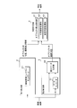
- FIG. 1 is a block diagram illustrating a hardware configuration of the anomaly detection device according to the first embodiment.
- FIG. 2 is a functional block diagram illustrating a configuration example of the anomaly detection device according to the first embodiment.
- FIG. 3 is a flowchart showing a processing procedure relating to object detection.
- FIG. 4 is a flowchart showing the mapping process.
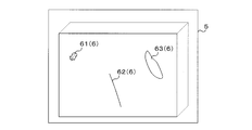
- FIG. 5A is an explanatory diagram illustrating an object detection method by the first detection unit.
- FIG. 5B is an explanatory diagram illustrating an object detection method by the first detection unit.
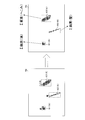
- FIG. 6 is an explanatory diagram illustrating an object detection method by the second detection unit.
- FIG. 7 is an explanatory diagram showing a method for determining the position and type of an object in pixel units.
- FIG. 5A is an explanatory diagram illustrating an object detection method by the first detection unit.
- FIG. 5B is an explanatory diagram illustrating an object detection method by the first detection unit.
- FIG. 6 is an explanatory diagram
- FIG. 8 is a flowchart showing a processing procedure for measuring the dimensions of an object.
- FIG. 9 is an explanatory diagram showing a method for measuring the size of an object.
- FIG. 10 is a flowchart showing the object quality judgment processing procedure.
- FIG. 11 is an explanatory diagram showing a method of determining the quality of an object.
- FIG. 12A is an explanatory diagram illustrating a method of detecting overlapping objects and measuring a dimension.
- FIG. 12B is an explanatory diagram showing a method of detecting overlapping objects and measuring dimensions.
- FIG. 12C is an explanatory diagram showing a method of detecting overlapping objects and measuring dimensions.
- FIG. 12D is an explanatory diagram showing a method of detecting overlapping objects and measuring dimensions.
- FIG. 12A is an explanatory diagram illustrating a method of detecting overlapping objects and measuring a dimension.
- FIG. 12B is an explanatory diagram showing a method of detecting overlapping objects and measuring dimensions.
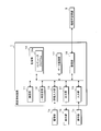
- FIG. 13 is a block diagram illustrating a configuration example of the incident detection system according to the second embodiment.
- FIG. 14 is a flowchart illustrating a processing procedure related to additional learning according to the second embodiment.
- FIG. 15 is a flowchart illustrating a processing procedure related to generation of learning data.
- FIG. 16 is an explanatory diagram showing a method of generating learning data.
- FIG. 17A is an explanatory diagram illustrating a method of generating learning data.
- FIG. 17B is an explanatory diagram illustrating a method of generating learning data.
- the bounding box surrounding the image of the foreign object may also include a background image, and the size of the foreign object is determined by the size of the bounding box. Cannot be specified. If the size of the foreign matter cannot be specified, it cannot be determined whether or not the foreign matter is allowable.
- An object of the present disclosure is to provide an object detection method, an object detection device, and a computer program that can detect the size and type of an object included in a captured image in pixel units.
- An object detection method is an object detection method for detecting an object included in a captured image, in which a position and a range of the object included in the captured image are specified by a bounding box, and the bounding is performed.
- the object is detected by a first method of detecting the type of the object surrounded by a box, and the object is detected by a second method of detecting the position of the object included in the captured image in pixel units.
- the position and type of the object based on the position and range of the object detected by the first method, the type of the object, and the position of the pixel of the object detected by the second method. Is determined in pixel units.
- an object is detected by two methods.
- the first method is a detection method that can roughly specify the position and range of an object, but can detect the type of the object.
- the second method is a detection method that can accurately detect the position of an object in pixel units, but cannot specify the type of the object.
- the object detection method according to the present disclosure is based on the position and range of an object specified and detected by the first method, the data of the type of the object, and the pixel position of the object detected in pixel units by the second method.
- the position and type of the object are determined in pixel units based on the data. Therefore, it is possible to detect the position and range of the object included in the captured image in pixel units.
- the order in which the object detection processing according to the first method and the object detection processing according to the second method are performed is not limited, and may be performed in the reverse order, or may be performed in parallel. May be.
- a threshold for performing a predetermined determination on the object is selected based on the type of the object, and the position and type of the object determined on a pixel-by-pixel basis, and the threshold selected based on the type, It is preferable that the predetermined determination is made based on the following.
- a captured image is an inspection target such as a manufactured part
- an object is an unusual phenomenon such as dust, hair, dents, or scratches attached to the part. Good or bad can be determined.
- the predetermined determination is made by comparing the total number of pixels of one type of the object with a threshold value selected based on the type.
- the predetermined determination is made by comparing the total number of pixels constituting one type of object with a threshold value corresponding to the one type.
- the total number of pixels corresponds to the size of dust, hair, dents, scratches, etc. attached to the component, and the quality of the inspection object is determined using different threshold values for each type of object. A defect can be determined.
- the detection of the object by the second method includes, when data of the captured image is input, a learned auto-encoder that outputs data of a feature extraction image in which the features of the input data are extracted. It is preferable to use such a structure.
- the position of the object can be accurately detected in pixel units by using the learned auto encoder.
- an object having various characteristics can be recognized, and the position and range of the object and the type of the object can be detected.
- the type of the object included in the captured image is determined by a third method different from the first method. Detecting, when the data of the captured image is input to the image recognition neural network, the position and range of the object and the type of the object detected by the third method are output. It is preferable that the image recognition neural network is additionally trained using an image and a detection result according to the third method.
- the detection result of the object according to the first method described in the aspect (1) does not match the detection result of the object according to the second method, in particular, the detection of the type of the object fails. If so, the type of the object is detected by the third method. Then, by additionally learning the image recognition neural network using the detection result by the third method, the accuracy of detecting the object by the first method can be automatically improved.
- the type of the object is detected based on a shape pattern of an outline of the object.
- the type of an object that cannot be detected by the image recognition neural network can be detected based on the contour pattern of the object, and the image recognition neural network can be additionally learned.
- the type of the object is received from a user, and when the data of the captured image is input to the image recognition neural network, It is preferable that the image recognition neural network is additionally learned using the captured image and the received type of the object so that the position and the range and the type of the object are output.
- the type of the object when the type of the object cannot be recognized even in the third method, the type of the object can be received from the user, and additional learning of the image recognition neural network can be performed using the received content. That is, according to the modes (6) and (7), the image recognition neural network is additionally learned as automatically as possible, and the unknown object that cannot be recognized even by the third method is assisted by the user. Perform additional learning. Therefore, even in an environment where an unknown object can occur, the image recognition neural network is additionally learned semi-automatically so that various objects can be recognized, and the positions and types of various objects can be detected in pixel units.
- object detection using the image recognition neural network and additional learning of the image recognition neural network can be performed in parallel. Therefore, the object detection processing can be continued even during the learning processing of the image recognition neural network.
- the captured image is an image obtained by imaging an inspection target, and the object to be detected is an abnormal part in the inspection target.
- the abnormal site and the type of the inspection object can be detected in pixel units.
- An object detection device is an object detection device that detects an object included in a captured image, and specifies a position and a range of the object included in the captured image using a bounding box.
- a first detection unit that detects the type of the object surrounded by a box, a second detection unit that detects the position of the object included in the captured image in pixel units, and the first detection unit that detects the position of the object included in the captured image.
- a determining unit that determines the position and type of the object in pixel units based on the position and range of the object, the type of the object, and the position of the pixel of the object detected in pixel units by the second detection unit; Is provided.
- the position and the type of the object included in the captured image can be detected in pixel units.
- a computer program of the present disclosure is a computer program for causing a computer to detect an object included in a captured image, and instructs the computer to use a bounding box to indicate the position and range of the object included in the captured image.
- a second method of identifying and detecting the object in a first method of detecting the type of the object surrounded by the bounding box, and detecting the position of the object included in the captured image in pixel units Detecting the object, based on the position and range of the object detected by the first method, the type of the object, and the position of the pixel of the object detected by the second method, The position and type of the object in pixel units To execute a process of constant to.
- the computer can function as the object detection device according to the mode (11).
- a computer program is a computer program for causing a computer to display information obtained by detecting an object included in a captured image, and stores the position of the object included in the captured image in the computer. And a range specified by a bounding box, information obtained by detecting the object by a first method of detecting a type of the object surrounded by the bounding box, and the object included in the captured image. And a process for displaying information based on the information obtained by detecting the object by the second method of detecting the position of the object in pixel units.
- information based on information obtained by detecting an object by the first method and information obtained by detecting an object by the second method for example, an object detected in pixel units
- the information about the position and type of can be displayed.
- FIG. 1 is a block diagram illustrating a hardware configuration of the anomaly detection device 1 according to the first embodiment.
- the anomaly detection device 1 (object detection device) is a computer having an arithmetic unit 11 such as one or more CPUs (Central Processing Units), a multi-core CPU, a GPU (Graphics Processing Unit), a TPU (Tensor Processing Unit), and the like.
- a temporary storage unit 12, an image input unit 13, an output unit 14, an input unit 15, a storage unit 16, and a data storage unit 17 are connected to the arithmetic unit 11 via a bus line.
- the anomaly detection device 1 according to the first embodiment acquires image data of a captured image 5 (see FIG.
- the inspection object is, for example, a connector that forms a wire harness.
- the arithmetic unit 11 controls the operation of each component by executing a computer program 16a described later stored in the storage unit 16.
- the calculation unit 11 performs a process of detecting a position and a type of the object 6 included in the captured image 5 obtained by capturing the inspection target object on a pixel-by-pixel basis, and detecting a change in the inspection target object. Details of the processing content will be described later.
- the temporary storage unit 12 is a memory such as a DRAM (Dynamic RAM) or an SRAM (Static RAM), and is a computer program 16a read from the storage unit 16 when the arithmetic processing of the arithmetic unit 11 is executed, or by the arithmetic processing. The resulting various data is temporarily stored.
- DRAM Dynamic RAM
- SRAM Static RAM
- the storage unit 16 is a nonvolatile memory such as a hard disk, an electrically erasable programmable ROM (EEPROM), and a flash memory.
- the storage unit 16 executes a process of detecting the position and type of the object 6 included in the captured image 5 on a pixel-by-pixel basis and detecting an anomaly of the inspection object by the operation unit 11 controlling the operation of each component.
- a computer program 16a for executing the program.
- the storage unit 16 recognizes the shape of the various objects 6 and information such as feature amounts for detecting the type of the object 6 included in the captured image 5.
- a threshold for determining whether or not it is stored is stored.
- the threshold value differs for each type of the object 6, and the storage unit 16 stores different threshold values in association with the types of the plurality of objects 6.
- the storage unit 16 may store the computer program 16a read from a recording medium by a reading device (not shown).
- the recording medium is an optical disk such as a CD (Compact Disc) -ROM, a DVD (Digital Versatile Disc) -ROM, a BD (Blu-ray (registered trademark) Disc), a magnetic disk such as a flexible disk and a hard disk, a magnetic optical disk, and a semiconductor memory. It is.
- the computer program 16a according to the first embodiment may be downloaded from an external computer (not shown) connected to a communication network (not shown) and stored in the storage unit 16.
- the image input unit 13 is an interface to which the imaging unit 1a is connected.
- the imaging unit 1a converts the image formed by the lens into an electric signal, such as a CCD or a CMOS, and converts the electric signal converted by the image pickup device into digital image data.
- the image data output from the imaging unit 1a is input to the incident detection device 1 via the image input unit 13.
- the imaging unit 1a and the incident detection device 1 may be connected by a dedicated cable, or may be connected via a network such as a LAN (Local Area Network).
- the image data is digital data in which each pixel arranged vertically and horizontally is represented by a luminance value of a predetermined gradation. In the present embodiment, a description will be given assuming that the image data is monochrome image data.
- the output unit 14 is an interface to which the display unit 1b is connected.
- the display unit 1b is a liquid crystal panel, an organic EL display, an electronic paper, a plasma display, or the like.
- the display unit 1b displays various information corresponding to the image data provided from the calculation unit 11. For example, the content of the abnormal detection result, an image of a defective inspection object, and the like are displayed.
- the display unit 1b is an example of an external output device that outputs an abnormal change detection result, and may be a buzzer, a speaker, a light emitting element, or another notification device. The worker of the factory can recognize the state of the inspection object and the like as a result of the abnormal detection from the image displayed on the display unit 1b.
- Operation unit 1c such as a keyboard, a mouse, and a touch sensor is connected to input unit 15.
- a signal indicating the operation state of the operation unit 1c is input to the incident detection device 1 via the input unit 15.
- the calculation unit 11 can recognize the operation state of the operation unit 1c via the input unit 15.
- the data storage unit 17 is a nonvolatile memory such as a hard disk, an EEPROM, and a flash memory, like the storage unit 16.
- the data storage unit 17 stores data such as the image data of the inspection object and the abnormal detection result.
- FIG. 2 is a functional block diagram illustrating a configuration example of the anomaly detection device 1 according to the first embodiment.
- the abnormality detection device 1 includes a first detection unit 2, a second detection unit 3, and a pass / fail determination unit 4 as functional units.
- Each functional unit of the incident detection device 1 is realized by hardware such as the arithmetic unit 11 and the temporary storage unit 12.
- the first detection unit 2 recognizes the image of the object 6 included in the captured image 5 and detects the position, the range, and the type of the object 6. Specifically, when data of the captured image 5 is input, the first detection unit 2 outputs the position and range of one or more objects 6 included in the captured image 5 and the type of the object 6
- the image recognition neural network 21 is provided.
- the position of the object 6 is specified by the position and size of the bounding box 7 surrounding the object 6 (see FIG. 5B).
- the bounding box 7 is, for example, rectangular and has a width and a height such that the object 6 is substantially inscribed.
- the image recognition neural network 21 can be configured using, for example, a known Tensorflow (registered trademark).
- the image recognition neural network 21 can be configured using another known convolutional neural network (CNN).
- CNN convolutional neural network
- the image recognition neural network 21 performs machine learning using image data of the object 6 and information indicating the type of the object 6 as teacher data so that the type of the object 6 included in the captured image 5 is output.
- the second detector 3 includes an auto encoder 31 and a difference data generator 32.
- the auto encoder 31 is a functional unit that receives image data output from the imaging unit 1a and outputs image data of a feature extraction image 5a obtained by extracting features of the inspection target included in the captured image 5 (see FIG. 6). ). Specifically, when the image data is input, the auto encoder 31 outputs the image data of the feature extraction image 5a representing the feature of the normal inspection object.
- the captured image 5 may include an image of dust, a scratch, a shadow, an abnormal part of the inspection object itself, or the like.
- the feature extraction image 5a is a captured image 5 that is obtained by removing these images and reproducing an ideal inspection target that is obtained when a normal inspection target having no abnormal change is captured.
- Auto-encoding is realized by a neural network.
- the neural network includes an intermediate layer that compresses image data in a dimension, and inputs and outputs image data having the same number of pixels.
- the auto encoder 31 has an input layer 31a, an output layer 31b, a convolution layer (CONV layer) 31c, and a deconvolution layer (DECONV layer) 31d.
- the input layer 31a is a layer to which data of each pixel value related to image data is input.
- the convolution layer 31c is a layer for dimensionally compressing image data. For example, the convolution layer 31c performs dimensional compression by performing convolution integration. The feature amount of the inspection object is extracted by the dimensional compression.
- the deconvolution layer 31d is a layer for restoring the data dimensionally compressed by the convolution layer 31c to the original dimensions. The deconvolution layer 31d performs a deconvolution process to restore the original dimension.
- the output layer 31b is a layer that outputs data of each pixel value of the feature extraction image 5a from which the features of the inspection object are extracted by the convolution layer 31c and the deconvolution layer 31d.
- the auto encoder 31 causes the neural network of the auto encoder 31 to perform machine learning so that the input image data and the output image data are the same. That is, the neural network is machine-learned so that the input captured image 5 and the output feature extraction image 5a are the same. Such machine learning is performed using image data obtained by imaging a normal inspection target.
- the difference data generation unit 32 calculates a difference between the image data obtained from the imaging unit 1a and the image data output from the auto encoder 31. Specifically, the difference data generation unit 32 calculates the difference between the pixel values of the pixels at the same location in each image data for each pixel. Then, the difference data generation unit 32 performs binarization by comparing the difference between the pixel values and a predetermined threshold. By the binarization processing, an image including the image of the object 6 detected in pixel units is obtained.
- a differential image 5b an image including the object 6 detected in pixel units is referred to as a differential image 5b (see FIG. 6).
- the pass / fail determination unit 4 includes an object detection processing unit 41, a dimension measurement processing unit 42, and a pass / fail determination processing unit 43.
- the object detection processing unit 41 is a functional unit that detects the position and type of one or a plurality of objects 6 included in the captured image 5 in pixel units.
- the dimension measurement processing unit 42 is a functional unit that measures the dimensions of each object 6 detected in pixel units.
- the pass / fail determination processing unit 43 executes a process of comparing the size of the object 6 with a threshold value according to the type of the object 6 to determine whether the change is acceptable, that is, determine whether the change is acceptable. It is a functional unit.
- FIG. 3 is a flowchart illustrating a processing procedure related to object detection.
- the calculation unit 11 acquires the image data output from the imaging unit 1a (Step S11).
- the calculation unit 11 detects the position and the type of the object 6 included in the captured image 5 on a pixel-by-pixel basis by executing a mapping process described later (step S12).
- the calculation unit 11 measures the size of the detected object 6 (step S13), and determines the quality of the object 6 (step S14).
- the calculation unit 11 determines the quality of the inspection object based on the determination result of step S14 (step S15). That is, the operation unit 11 determines whether or not there is an allowable incident. If it is determined to be good (step S15: YES), the calculation unit 11 ends the processing. If it is determined that the inspection object is defective (step S15: NO), the calculation unit 11 executes a predetermined process for coping with the abnormal condition of the inspection target (step S16), and ends the process. For example, the calculation unit 11 executes a process of notifying that the inspection target has an abnormality. Further, the calculation unit 11 executes a process of displaying an image indicating the result of the pass / fail judgment (see the right diagram in FIG. 11) on the display unit 1b.
- the information of the image indicating the result of the pass / fail determination is an example of information based on information obtained by the detection processing by the first detection unit 2 and information obtained by the detection processing by the second detection unit 3.
- FIG. 4 is a flowchart showing a mapping processing procedure.
- the first detection unit 2 specifies the position and range of one or more objects 6 included in the captured image 5 with the bounding box 7 and detects the type of the object 6 surrounded by the bounding box 7 (Step S31). ).
- FIGS. 5A and 5B are explanatory diagrams illustrating an object detection method by the first detection unit 2.
- FIG. 5A shows the captured image 5
- FIG. 5B shows the captured image 5 showing the detection result of the object 6.
- the captured image 5 includes a plurality of objects 6.
- an object 61 that is a dust image, an object 62 that is a hair image, an object 63 that is a dent image, and the like are included.
- each object 6 detected by the first detection unit 2 is surrounded by a bounding box 7, and the position of the object 6 is represented by the position and size of the bounding box 7.
- the bounding box 71 indicates the position and range of the dust object 61
- the bounding box 72 indicates the position and range of the hair object 62
- the bounding box 73 indicates the position and range of the dent object 63. I have.
- the type of the object 6 included in the bounding box 7 is displayed. As described above, according to the first detection unit 2, the approximate position, range, and type of each object 6 included in the captured image 5 are specified.
- the second detection unit 3 detects the object 6 included in the captured image 5 on a pixel basis (Step S32).
- FIG. 6 is an explanatory diagram showing an object detection method by the second detection unit 3.
- the image data of the captured image 5 is input to the auto encoder 31, the image data of the feature extraction image 5a representing the original characteristics of the captured image 5 from which the abnormal part has been removed is output.
- the difference data generation unit 32 calculates a difference between the acquired original image data and the image data output from the auto encoder 31. Specifically, the difference data generation unit 32 calculates the difference between the pixel values of the pixels at the same location in each image data for each pixel. Then, the difference data generation unit 32 performs binarization by comparing the difference between the pixel values and a predetermined threshold. By the binarization processing, an image including the image of the object 6 detected in pixel units is obtained.
- an image including the object 6 detected in pixel units is referred to as a differential image 5b.
- the difference image 5b does not include the inspection target itself, but includes only the object 6 that is the abnormal site.
- the difference image 5b includes an object 61 that is a dust image, an object 62 that is a hair image, and an object 63 that is a dent image.
- the calculation unit 11 determines the position and the type of the object 6 on a pixel-by-pixel basis by the mapping process (step S33), and ends the process related to the object detection.
- the calculation unit 11 that performs the process of step S33 functions as a determination unit that determines the position and type of the object 6 on a pixel basis based on the detection results of the first detection unit 2 and the second detection unit 3.
- FIG. 7 is an explanatory diagram illustrating a method for determining the position and type of the object 6 in pixel units.
- the upper left diagram is a captured image 5 on which the detection result of the object 6 by the first detection unit 2 is reflected.
- the position of each object 6 included in the captured image 5 is represented by the position and size of the bounding box 7.
- the type of each object 6 is represented by a label attached to the bounding box 7.
- the bounding box 7 indicates the type of the object 6, but does not have accurate information on the position, shape, or size of the object 6.
- the lower left diagram is a difference image 5b reflecting the detection result of the object 6 by the second detection unit 3.
- Each pixel of the object 6 included in the difference image 5b accurately indicates the position or shape of the object 6 in pixel units, but does not have information on the type of the object 6.
- the middle diagram conceptually shows a state in which the bounding box 7 is mapped on the difference image 5b output from the second detection unit 3. By mapping the bounding box 7 to the difference image 5b, it becomes possible to determine the type of the object 6 in pixel units. That is, by associating the one type with the pixels of the object 6 included in the one type of bounding box 7, the type of the object 6 can be determined in pixel units.
- the right diagram conceptually shows a state in which the type of the object 6 is determined for each pixel. For example, the type “dust” is associated with each pixel constituting the dust object 61. Similarly, the type “hair” is associated with each pixel forming the hair object 62, and the type “dent” is associated with each pixel forming the dent object 63.
- FIG. 8 is a flowchart showing a processing procedure for measuring the size of the object 6, and FIG. 9 is an explanatory diagram showing a method for measuring the size of the object 6.
- the calculation unit 11 selects a pixel group of one type of the object 6 (step S51). That is, a group of a plurality of pixels constituting one object 6 is selected. For example, as shown in FIG. 9, a group of a plurality of pixels constituting the dust object 61 is selected. A plurality of pixels having different types of the object 6 are not selected as a group of pixels even if they are connected or adjacent. Further, even if a plurality of pixels of the same type of the object 6 are separated by a predetermined pixel or more, they are not selected as a group of pixels.
- the calculation unit 11 calculates the total number of pixels of a group of the selected object 6 as shown in the right diagram of FIG. 9 (step S52).
- the total number of pixels constituting the dust object 61 is 13.
- the total number of pixels constituting hair is 19.
- the total number of pixels constituting the object 6 corresponds to the size of the object 6.
- the shape of the object 6 is various, such as a lump-shaped object or a linear object, but the objects 6 of the same type have substantially the same shape. Therefore, if the type of the object 6 is known, the total number of pixels constituting the object 6 can be used as information indicating the size of the object 6.
- the total number of pixels constituting the hair object 62 corresponds to the length of the hair.
- the total number of pixels constituting the dust object 61 substantially corresponds to the product of the vertical and horizontal dimensions.
- the calculation unit 11 determines whether or not the dimension measurement of all the objects 6 included in the difference image 5b has been completed (Step S53). If it is determined that there is an object 6 for which measurement has not been completed (step S53: NO), the process returns to step S51, and the same calculation processing is executed for the other objects 6 whose dimensions have not been measured. When it is determined that the measurement processing of all the objects 6 has been completed (step S53: YES), the calculation unit 11 ends the processing related to the dimension measurement.
- FIG. 10 is a flowchart showing a procedure for determining whether or not the object 6 is good
- FIG. 11 is an explanatory diagram showing a method for determining whether the object 6 is good.
- the calculation unit 11 selects a threshold value corresponding to the type of the pixel group of the object 6 that is the target of the quality determination (step S71).
- the storage unit 16 stores a different threshold value for each type of the object 6, and the calculation unit 11 selects a threshold value associated with the type of the object 6 to be determined.
- the calculation unit 11 compares the total number of pixels of the object 6 as the quality determination target with the threshold value selected in step S71 (step S72), and stores the comparison result (step S73). For example, when the total number of pixels constituting one object 6 is equal to or greater than a threshold, the calculation unit 11 stores information indicating that the object 6 is an unacceptable anomaly. When the total number of pixels is less than the threshold value, information indicating that the object 6 is an allowable incident is stored. As shown in FIG. 11, the total number of pixels indicating the size of dust ( ⁇ pixel) is smaller than the first threshold value related to dust, so that it is determined to be acceptable.
- step S74 determines whether the quality judgment has been completed for all the objects 6 (step S74). If it is determined that there is an object 6 for which the quality determination has not been completed (step S74: NO), the process returns to step S71, and the same calculation process is executed for the other objects 6 whose quality has not been measured. When it is determined that the quality determination has been completed for all the objects 6 (step S74: YES), the calculation unit 11 ends the processing related to the quality determination.
- the state in which the plurality of objects 6 included in the captured image 5 are separated from each other has been described as an example.
- the objects 6 Detection, dimension measurement, and abnormality determination can be performed.
- FIG. 12A, 12B, 12C, and 12D are explanatory diagrams illustrating a method of detecting the overlapping object 6 and measuring the dimension.
- FIG. 12A shows a state where dust and hair objects 61 and 62 overlap each other.
- the second detection unit 3 detects a plurality of pixels constituting the dust and hair objects 61 and 62 as a group of pixels without distinguishing the type of each object 6.
- FIG. 12B shows a state mapped by the bounding box 71 indicating the position and range of the dust.
- the calculation unit 11 recognizes a pixel group included in the bounding box 71 as a pixel constituting the dust object 61, and assigns a type “dust” to each pixel.
- FIG. 12A shows a state where dust and hair objects 61 and 62 overlap each other.
- the second detection unit 3 detects a plurality of pixels constituting the dust and hair objects 61 and 62 as a group of pixels without distinguishing the type of each object 6.
- FIG. 12B
- FIG. 12C shows a state mapped by the bounding box 72 indicating the position and range of the hair.
- the calculation unit 11 recognizes the pixel group included in the bounding box 72 as a pixel constituting the hair object 62, and assigns the type “hair” to each pixel.
- FIG. 12D shows the result of recognizing the type of the object 6 in pixel units by the mapping processing shown in FIGS. 12B and 12C. Pixels shown in black are given the type “hair”. Pixels with hatching are given the type “dust”. The white pixels are given both the types “dust” and “hair”. In this way, by assigning both types to the pixels of the portion where the object 6 overlaps, it is possible to measure the dimensions of each object 6 even if the objects 6 overlap.
- the pixels to which the type of “dust” is assigned are hatched pixels and white pixels, and the size of the “dust” object 61 is measured by calculating the total number of the pixels. be able to.
- the pixels to which the type of “hair” is given are black pixels and white pixels, and by calculating the total number of the pixels, the size of the “hair” object 62 is measured. Can be. In this way, even if a plurality of types of objects 6 overlap, the position and type of each object 6 can be detected in pixel units, and the dimensions of each object 6 can be measured.
- the first detection unit 2 and the second detection unit 3 detect the object 6 and perform the mapping process illustrated in FIG.
- the position and type can be detected in pixel units. Since it is possible to detect the position and type of the object 6 in pixel units, it is possible to accurately measure the size of the object 6 that is an abnormal site. Further, the abnormal site detected in pixel units and the quality thereof can be displayed as shown in FIG. For example, it is possible to detect an abnormal site and a type of an inspection object such as a connector constituting a wire harness on a pixel-by-pixel basis, and to accurately calculate the dimensions of the abnormal site.
- the above determination can be performed by a simple process of comparing the total number of pixels of the object 6 detected in pixel units with a threshold value without performing different measurement calculation processes according to the shape of the object 6. That is, it is possible to determine whether or not the size of the abnormal site is an allowable size without calculating the size of the abnormal site by complicated processing.
- the position of the object 6 can be accurately detected in pixel units. Further, the size of the object 6 can be accurately calculated.
- the object 6 having various features can be recognized, and the position, range and type of the object 6 can be detected.
- one computer operates as the anomaly detection device 1 and functions as the first detection unit 2, the second detection unit 3, the pass / fail determination unit 4, and the like. May be configured to cause a cloud computer to execute a part or all of the processing for realizing. Further, a configuration may be adopted in which the processing for realizing each functional unit is executed by a virtual machine, such as by being executed by a plurality of computers.
- the system for mainly detecting whether the inspection target is good or bad has been described.
- the content of the detection target object 6 is not particularly limited.
- FIG. 13 is a block diagram illustrating a configuration example of the anomaly detection system according to the second embodiment.
- the anomaly detection system according to the second embodiment includes an anomaly detection device 1 and a machine learning device 9.
- the anomaly detection device 1 is installed, for example, in a factory where the inspection object is manufactured, and the machine learning device 9 is installed in a facility outside the factory.
- the incident detection device 1 has the same configuration as that of the first embodiment, and further includes a communication unit 18 for transmitting and receiving data to and from the machine learning device 9.
- the machine learning device 9 is a server device that additionally learns the image recognition neural network 21 constituting the anomaly detection device 1.
- the machine learning device 9 is a computer, and the basic hardware configuration is the same as that of the incident detection device 1.
- the anomaly detection device 1 and the machine learning device 9 are separate computers, and operate by executing programs in parallel. Specifically, the anomaly detection device 1 provides a copy of the image recognition neural network 21 to the machine learning device 9 and, while the anomaly detection device 1 executes a process of detecting an anomaly of the inspection object, the machine learning The device 9 can execute an additional learning process of the image recognition neural network 21. The anomaly detection device 1 continues the anomaly detection process using the image recognition neural network 21 before learning, not the image recognition neural network 21 during learning. The machine learning device 9 transmits to the machine learning device 9 various parameters for configuring the image recognition neural network 21, for example, parameters such as the number of layers of the image recognition neural network 21, the number of neurons, the type of the neural network, and the weight coefficient. By doing so, a copy of the image recognition neural network 21 is provided.
- the anomaly detection device 1 adds, when the position and range of the object 6 detected by the first detection unit 2 and the position of the object 6 detected by the second detection unit 3 do not match during the abnormality detection process. Requests processing related to learning from the machine learning device 9.
- FIG. 14 is a flowchart illustrating a processing procedure related to additional learning according to the second embodiment.
- the calculation unit 11 of the incident detection device 1 acquires image data from the imaging unit 1a and executes a process related to detection of the object 6 (step S111).
- the flowchart is simplified by omitting a processing block for acquiring image data, specific processing contents are the same as those in the first embodiment.
- the calculation unit 11 determines whether the detection of the object 6 has succeeded (step S112). Specifically, the calculation unit 11 determines the position and range of the object 6 specified by the first detection unit 2 in the bounding box 7 and the position of the pixel of the object 6 detected by the second detection unit 3. If they match, it is determined that the detection of the object 6 has succeeded. If they do not match, it is determined that the detection of the object 6 has failed.
- a state in which the type of the object 6 is not detected by the first detection unit 2 even though the pixel of the object 6 is detected by the second detection unit 3 is an example of detection failure. It will be described as.
- step S112 If it is determined that the detection of the object 6 has not failed (step S112: NO), the arithmetic unit 11 executes the processes related to the dimension measurement and the pass / fail determination of the object 6 in steps S113 and S114, as in the first embodiment. .
- the flowchart is simplified by omitting processing blocks at the time of pass / fail determination, specific processing contents are the same as in the first embodiment.
- step S112 When it is determined in step S112 that the detection of the object 6 has failed (step S112: YES), the calculation unit 11 transmits the current image recognition neural network 21 to the machine learning device 9 via the communication unit 18 (step S115). Specifically, various parameters for configuring the image recognition neural network 21 are transmitted to the machine learning device 9.
- the machine learning device 9 receives the image recognition neural network 21 transmitted from the anomaly detection device 1 as an additional learning target (step S116).
- step S115 After having completed the processing of step S115, the anomaly detection device 1 executes processing relating to generation of learning data (step S117).
- FIG. 15 is a flowchart showing a processing procedure for generating learning data
- FIGS. 16 and 17 are explanatory diagrams showing a method for generating learning data.
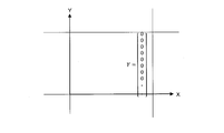
- the calculation unit 11 divides the captured image 5 in which the detection of the object 6 has failed in a grid pattern as shown in the right diagram of FIG. 16, and assigns an array Y indicating information on the object 6 to each of the divided image blocks. Assigned (step S131).
- the array Y is represented, for example, by the following formula (1).
- the initial value of each variable of the array allocated in step S131 is 0.
- the variable P in the array Y indicates whether or not the object 6 is included in the image block.
- the variables Bx and By indicate the center position of the object 6, for example, the X coordinate and the Y coordinate of the center of gravity of the image.
- the method of setting the coordinate system is not particularly limited.
- the origin is set at the lower left vertex of each image block, and the horizontal direction of the captured image 5 is set as the X axis, and the vertical direction is set as the Y axis. It is preferable to use a rectangular coordinate system that performs the following.
- the variables Bw and Bh indicate the width and height of the object 6.
- the operation unit 11 that has completed the processing in step S131 refers to the detection result of the second detection unit 3, and specifies the presence / absence, position, and size of the object 6 in each image block (step S132). Then, the arithmetic unit 11 substitutes the corresponding numerical values into the variables P, Bx, By, Bw, and Bh of the array Y assigned to each image block according to the specified result as shown in FIGS. S133). When the object 6 is not included in the image block, each variable of the array Y is 0.
- the calculation unit 11 detects the type of the object 6 whose type has not been specified by executing a known shape recognition process on the captured image 5 (step S134). For example, the calculation unit 11 detects an edge of the object 6, calculates a predetermined feature amount, and compares the calculated feature amount with the feature amount stored in the storage unit 16 to specify the type of the object 6 corresponding to the similar feature amount. By doing so, the type of the object 6 is detected. Alternatively, the type of the object 6 may be specified by pattern matching.
- step S134 determines whether the type of the object 6 has been successfully detected (step S135). If it is determined that the calculation has succeeded (step S135: YES), the arithmetic unit 11 substitutes the corresponding numerical values into the variables C1, C2, C3... According to the detection result of step S134 (step S137), Is completed.
- step S135 the calculation unit 11 receives the type of the object 6 from the user using the operation unit 1c (step S136). For example, the calculation unit 11 may display the picked-up image 5 in question on the display unit 1b and display an instruction image indicating an image portion in which the detection of the object 6 has failed. For example, a frame image surrounding the pixel group of the object 6 detected by the second detection unit 3 without being detected by the first detection unit 2 may be displayed so as to be superimposed on the captured image 5. The frame image is an example, and may be an arrow image or the like.
- the calculation unit 11 presents a plurality of types that are assumed to the user, and receives the selection of the type by the user. If the type is a new type, the calculation unit 11 may receive registration of the type name. The calculation unit 11 receives a name of a new type from the user, and changes and registers a variable name of the type “undecided” to the name.
- step S137 the arithmetic unit 11 substitutes the corresponding numerical values into the variables C1, C2, C3,... According to the content received in step S136 (step S137), and ends the learning data generation process.
- the arithmetic unit 11 substitutes the corresponding numerical values into the variables C1, C2, C3,... According to the content received in step S136 (step S137), and ends the learning data generation process.
- Step S118 ⁇ Computing unit 11 that has completed the processing related to generation of learning data in step S117 stores the generated learning data in data storage unit 17 (step S118). Then, the arithmetic unit 11 determines whether a predetermined amount of learning data has been accumulated (step S119). If it is determined that the predetermined amount of learning data has not been accumulated (step S119: NO), the arithmetic unit 11 returns the process to step S113, and continues the anomaly detection process and accumulation of the learning data. When it is determined that a predetermined amount of learning data has been stored (step S119: YES), the arithmetic unit 11 transmits the learning data stored in the data storage unit 17 to the machine learning device 9 through the communication unit 18 ( Step S120).
- the machine learning device 9 receives the learning data transmitted from the anomaly detection device 1 (step S121), and additionally learns the image recognition neural network 21 received in step S116 using the learning data (step S122). ). That is, when the image data of the captured image 5 including the unrecognizable object 6 is input to the image recognition neural network 21, the machine learning device 9 outputs data indicating the position, range, and type of the object 6. In this way, the image recognition neural network 21 is additionally trained using the learning data.
- the additional learning is supervised learning.
- the machine learning device 9 transmits the image recognition neural network 21 additionally learned in step S122 to the anomaly detection device 1 (step S123).
- the incident detection apparatus 1 receives the additionally learned image recognition neural network 21 transmitted from the machine learning apparatus 9 by the communication unit 18 (Step S124).
- the arithmetic unit 11 of the anomaly detection device 1 updates the image recognition neural network 21 before the additional learning to a new image recognition neural network 21 after the additional learning (step S125), and returns the process to step S111.
- the learning data is automatically accumulated.
- the additional learning of the image recognition neural network 21 can be performed.
- the type of the object 6 when the type of the object 6 is not detected by using the image recognition neural network 21, the type of the object 6 can be detected by shape recognition, and the image recognition neural network 21 can be additionally learned.
- additional learning data can be generated by accepting the type of the object 6 from the user, and the image recognition neural network 21 can be additionally learned.
- the detection of the object 6 or the abnormal detection of the inspection object and the additional learning of the image recognition neural network 21 can be executed in parallel. Therefore, the detection process of the object 6 can be continued even during the learning process of the image recognition neural network 21.
Landscapes
- Engineering & Computer Science (AREA)
- Computer Vision & Pattern Recognition (AREA)
- Physics & Mathematics (AREA)
- General Physics & Mathematics (AREA)
- Theoretical Computer Science (AREA)
- Image Analysis (AREA)
Abstract
撮像画像に含まれるオブジェクトを検出するオブジェクト検出方法であって、撮像画像に含まれるオブジェクトの種類を検出し、撮像画像に含まれるオブジェクトを画素単位で検出し、オブジェクトの種類、及び画素単位で検出されたオブジェクトの画素に基づいて、オブジェクトの大きさ及び種類を画素単位で決定する。
Description
本開示はオブジェクト検出方法、オブジェクト検出装置及びコンピュータプログラムに関する。
本出願は、2018年8月6日出願の日本出願第2018-147979号に基づく優先権を主張し、前記日本出願に記載された全ての記載内容を援用するものである。
本出願は、2018年8月6日出願の日本出願第2018-147979号に基づく優先権を主張し、前記日本出願に記載された全ての記載内容を援用するものである。
工業的に生産される部品を撮像し、撮像して得られる良品及び不良品の撮像画像を教師データとしてニューラルネットワークを深層機械学習させることにより、学習済みニューラルネットワークを用いた部品の良否判定を行うことができる。
一方、Tensorflow(登録商標)を用いた画像認識技術を利用することにより、撮像画像に含まれるオブジェクトの位置及び範囲、当該オブジェクトの種類を検出する技術がある。例えば、撮像画像に含まれる人物、動物、車両等の画像部分を検出することができる。
また、非特許文献1は、オートエンコーダを用いて、データの特徴量を自己学習する技術を開示している。
また、非特許文献1は、オートエンコーダを用いて、データの特徴量を自己学習する技術を開示している。
G. E. Hinton and R. Salakhutdinov, "Reducing the Dimensionality of Data with Neural Networks", Science, vol. 313, p. 504-507
本開示のオブジェクト検出方法は、撮像画像に含まれるオブジェクトを検出するオブジェクト検出方法であって、前記撮像画像に含まれる前記オブジェクトの種類を検出する第1の方式にて前記オブジェクトを検出し、前記撮像画像に含まれる前記オブジェクトを画素単位で検出する第2の方式にて前記オブジェクトを検出し、前記第1の方式にて検出された前記オブジェクトの種類、及び前記第2の方式にて検出された前記オブジェクトに基づいて、前記オブジェクトの大きさ及び種類を画素単位で決定し、前記オブジェクトに関して所定の判定を行うための閾値を、該オブジェクトの種類に基づいて選択し、画素単位で決定された前記オブジェクトと、前記種類に基づいて選択された閾値とに基づいて前記所定の判定を行う。
本開示のオブジェクト検出装置は、撮像画像に含まれるオブジェクトを検出するオブジェクト検出装置であって、前記撮像画像に含まれる前記オブジェクトの種類を検出する第1検出部と、前記撮像画像に含まれる前記オブジェクトを画素単位で検出する第2検出部と、前記第1検出部にて検出された前記オブジェクトの種類、及び前記第2検出部にて画素単位で検出された前記オブジェクトに基づいて、前記オブジェクトの大きさ及び種類を画素単位で決定する決定部と、前記オブジェクトに関して所定の判定を行うための閾値を、該オブジェクトの種類に基づいて選択する選択部と、画素単位で決定された前記オブジェクトと、前記種類に基づいて選択された閾値とに基づいて前記所定の判定を行う判定部とを備える。
本開示のコンピュータプログラムは、コンピュータに撮像画像に含まれるオブジェクトを検出させるためのコンピュータプログラムであって、前記コンピュータに、前記撮像画像に含まれる前記オブジェクトの種類を検出する第1の方式にて前記オブジェクトを検出し、前記撮像画像に含まれる前記オブジェクトを画素単位で検出する第2の方式にて前記オブジェクトを検出し、前記第1の方式にて検出された前記オブジェクトの種類、及び前記第2の方式にて検出された前記オブジェクトに基づいて、前記オブジェクトの大きさ及び種類を画素単位で決定し、前記オブジェクトに関して所定の判定を行うための閾値を、該オブジェクトの種類に基づいて選択し、画素単位で決定された前記オブジェクトと、前記種類に基づいて選択された閾値とに基づいて前記所定の判定を行う処理を実行させる。
本開示のコンピュータプログラムは、コンピュータに撮像画像に含まれるオブジェクトを検出して得られる情報を表示させるためのコンピュータプログラムであって、前記コンピュータに、前記撮像画像に含まれる前記オブジェクトの種類を検出する第1の方式にて前記オブジェクトを検出して得られた情報と、前記撮像画像に含まれる前記オブジェクトを画素単位で検出する第2の方式にて前記オブジェクトを検出して得られた情報とに基づく情報を表示させる処理を実行させる。
なお、本願は、オブジェクト検出装置の一部又は全部を実現する半導体集積回路として実現したり、オブジェクト検出装置を含むその他のシステムとして実現したりすることができる。
[本開示が解決しようとする課題]
ところで、Tensorflow(登録商標)を用いた画像認識技術によれば、オブジェクトを囲むバウンディングボックスによって、当該オブジェクトの位置及び範囲をおおよそ特定することができるが、画素単位でオブジェクトの位置及び種類を検出することができないという問題がある。
ところで、Tensorflow(登録商標)を用いた画像認識技術によれば、オブジェクトを囲むバウンディングボックスによって、当該オブジェクトの位置及び範囲をおおよそ特定することができるが、画素単位でオブジェクトの位置及び種類を検出することができないという問題がある。
例えば、オブジェクトの種類を特定できても当該オブジェクトの寸法を正確に検出できない。部品に付着した髪のような線状の異物がオブジェクトとして検出されたとしても、当該異物の画像を囲むバウンディングボックスには、背景画像も多分に含まれ、バウンディングボックスの大きさから異物の大きさを特定することはできない。異物の大きさが特定できないと、許容される異変なのか否かを判断することができない。
本開示の目的は、撮像画像に含まれるオブジェクトの大きさ及び種類を画素単位で検出することができるオブジェクト検出方法、オブジェクト検出装置及びコンピュータプログラムを提供することにある。
[本開示の効果]
本開示によれば、撮像画像に含まれるオブジェクトの大きさ及び種類を画素単位で検出することができるオブジェクト検出方法、オブジェクト検出装置及びコンピュータプログラムを提供することが可能となる。
本開示によれば、撮像画像に含まれるオブジェクトの大きさ及び種類を画素単位で検出することができるオブジェクト検出方法、オブジェクト検出装置及びコンピュータプログラムを提供することが可能となる。
[本開示の実施形態の説明]
最初に本開示の実施態様を列記して説明する。また、以下に記載する実施形態の少なくとも一部を任意に組み合わせてもよい。
最初に本開示の実施態様を列記して説明する。また、以下に記載する実施形態の少なくとも一部を任意に組み合わせてもよい。
(1)本開示のオブジェクト検出方法は、撮像画像に含まれるオブジェクトを検出するオブジェクト検出方法であって、前記撮像画像に含まれる前記オブジェクトの位置及び範囲をバウンディングボックスにて特定すると共に、該バウンディングボックスによって囲まれる前記オブジェクトの種類を検出する第1の方式にて前記オブジェクトを検出し、前記撮像画像に含まれる前記オブジェクトの位置を画素単位で検出する第2の方式にて前記オブジェクトを検出し、前記第1の方式にて検出された前記オブジェクトの位置及び範囲、該オブジェクトの種類、並びに前記第2の方式にて検出された前記オブジェクトの画素の位置に基づいて、前記オブジェクトの位置及び種類を画素単位で決定する。
本開示にあっては、2つの方式でオブジェクトを検出する。第1の方式は、オブジェクトの位置及び範囲をおおよそ特定することができるが、オブジェクトの種類を検出することができる検出方法である。第2の方式は、オブジェクトの位置を画素単位で正確に検出することができるが、オブジェクトの種類を特定することができない検出方法である。
本開示のオブジェクト検出方法は、上記第1の方式で特定及び検出されたオブジェクトの位置及び範囲、並びに当該オブジェクトの種類のデータと、第2の方式により画素単位で検出されたオブジェクトの画素位置のデータとに基づいて、オブジェクトの位置及び種類を画素単位で決定する。
従って、撮像画像に含まれるオブジェクトの位置及び範囲を画素単位で検出することが可能である。
なお、第1の方式によるオブジェクトの検出処理と、第2の方式によるオブジェクトの検出処理とを実行する順序は限定されるものでは無く、逆順で実行しても良いし、同時並行的に実行しても良い。
本開示のオブジェクト検出方法は、上記第1の方式で特定及び検出されたオブジェクトの位置及び範囲、並びに当該オブジェクトの種類のデータと、第2の方式により画素単位で検出されたオブジェクトの画素位置のデータとに基づいて、オブジェクトの位置及び種類を画素単位で決定する。
従って、撮像画像に含まれるオブジェクトの位置及び範囲を画素単位で検出することが可能である。
なお、第1の方式によるオブジェクトの検出処理と、第2の方式によるオブジェクトの検出処理とを実行する順序は限定されるものでは無く、逆順で実行しても良いし、同時並行的に実行しても良い。
(2)前記オブジェクトに関して所定の判定を行うための閾値を、該オブジェクトの種類に基づいて選択し、画素単位で決定された前記オブジェクトの位置及び種類と、該種類に基づいて選択された閾値とに基づいて前記所定の判定を行う構成が好ましい。
本開示にあっては、オブジェクトの種類によって異なる閾値を選択し、画素単位で検出されたオブジェクトの位置及び種類と、当該種類に対応する閾値とに基づいて、所定の判定を行うことができる。
例えば、撮像画像は、製造される部品等の検査対象物、オブジェクトは、部品に付着した埃、髪、へこみ、傷等の異変であり、かかるオブジェクトの種類毎に異なる閾値を用いて、検査対象物の良、不良を判定することができる。
例えば、撮像画像は、製造される部品等の検査対象物、オブジェクトは、部品に付着した埃、髪、へこみ、傷等の異変であり、かかるオブジェクトの種類毎に異なる閾値を用いて、検査対象物の良、不良を判定することができる。
(3)前記オブジェクトの一の種類の画素の総数と、該種類に基づいて選択された閾値とを比較することによって、前記所定の判定を行う構成が好ましい。
本開示にあっては、一の種類のオブジェクトを構成する画素の総数と、当該一の種類に対応する閾値とを比較することによって、所定の判定を行う。
例えば、上記の検査対象物の例においては、画素の総数は部品に付着した埃、髪、へこみ、傷等の寸法に相当し、オブジェクトの種類毎に異なる閾値を用いて検査対象物の良、不良を判定することができる。
例えば、上記の検査対象物の例においては、画素の総数は部品に付着した埃、髪、へこみ、傷等の寸法に相当し、オブジェクトの種類毎に異なる閾値を用いて検査対象物の良、不良を判定することができる。
(4)前記第2の方式による前記オブジェクトの検出は、前記撮像画像のデータが入力された場合、入力された該データの特徴が抽出された特徴抽出画像のデータを出力する学習済みオートエンコーダを用いて行う構成が好ましい。
本開示にあっては、学習済みオートエンコーダを用いることによって、画素単位でオブジェクトの位置を正確に検出することができる。
(5)前記第1の方式による前記オブジェクトの検出は、前記撮像画像のデータが入力された場合、該撮像画像に含まれる前記オブジェクトの位置及び範囲並びに該オブジェクトの種類を出力する学習済みの画像認識ニューラルネットワークを用いて行う構成が好ましい。
本開示にあっては、学習済みの画像認識ニューラルネットワークを用いることによって、様々な特徴を有するオブジェクトを認識し、オブジェクトの位置及び範囲並びに当該オブジェクトの種類を検出することができる。
(6)前記第1の方式による検出結果と、前記第2の方式による検出結果が整合しない場合、前記第1の方式と異なる第3の方式にて前記撮像画像に含まれる前記オブジェクトの種類を検出し、前記画像認識ニューラルネットワークに前記撮像画像のデータが入力された場合、前記第3の方式にて検出された前記オブジェクトの位置及び範囲並びに該オブジェクトの種類が出力されるように、前記撮像画像及び前記第3の方式に係る検出結果を用いて、前記画像認識ニューラルネットワークを追加学習させる構成が好ましい。
本開示にあっては、態様(1)で説明した第1の方式によるオブジェクトの検出結果と、上記第2の方式によるオブジェクトの検出結果とが整合しない場合、特に、オブジェクトの種類の検出に失敗した場合、第3の方式でオブジェクトの種類を検出する。そして、第3方式による検出結果を用いて画像認識ニューラルネットワークを追加学習させることによって、第1の方式によるオブジェクトの検出精度を自動的に向上させることができる。
(7)前記第3の方式は、前記オブジェクトの輪郭線の形状パターンに基づいて前記オブジェクトの種類を検出する構成が好ましい。
本開示にあっては、画像認識ニューラルネットワークで検出できなかったオブジェクトの種類を、当該オブジェクトの輪郭線の形状パターンに基づいて検出し、上記画像認識ニューラルネットワークを追加学習させることができる。
(8)前記第3の方式にて前記オブジェクトの種類を検出できなった場合、該オブジェクトの種類をユーザから受け付け、前記画像認識ニューラルネットワークに前記撮像画像のデータが入力された場合、前記オブジェクトの位置及び範囲並びに該オブジェクトの種類が出力されるように、前記撮像画像及び受け付けた前記オブジェクトの種類を用いて、前記画像認識ニューラルネットワークを追加学習させる構成が好ましい。
本開示にあっては、第3の方式でもオブジェクトの種類を認識できなった場合、ユーザからオブジェクトの種類を受け付け、受け付けた内容を用いて画像認識ニューラルネットワークを追加学習させることができる。つまり上記態様(6)及び(7)により、可能な限り自動的に画像認識ニューラルネットワークを追加学習させると共に、第3の方式でも認識できない未知のオブジェクトに関してはユーザの人手を借りて画像認識ニューラルネットワークの追加学習を行う。
従って、未知のオブジェクトが発生し得る環境においても、各種オブジェクトを認識できるよう、半自動的に画像認識ニューラルネットワークを追加学習させ、種々のオブジェクトの位置及び種類を画素単位で検出可能となる。
従って、未知のオブジェクトが発生し得る環境においても、各種オブジェクトを認識できるよう、半自動的に画像認識ニューラルネットワークを追加学習させ、種々のオブジェクトの位置及び種類を画素単位で検出可能となる。
(9)前記画像認識ニューラルネットワークを用いた前記オブジェクトの検出と、該画像認識ニューラルネットワークの追加学習とを並行的に実行する構成が好ましい。
本開示にあっては、画像認識ニューラルネットワークを用いたオブジェクトの検出と、画像認識ニューラルネットワークの追加学習を並行的に実行することができる。従って、画像認識ニューラルネットワークの学習処理中も、オブジェクトの検出処理を継続することができる。
(10)前記撮像画像は検査対象物を撮像して得た画像であり、検出対象の前記オブジェクトは該検査対象物における異変部位である構成が好ましい。
本開示にあっては、検査対象物の異変部位及び種類を、画素単位で検出することができる。
(11)本開示のオブジェクト検出装置は、撮像画像に含まれるオブジェクトを検出するオブジェクト検出装置であって、前記撮像画像に含まれる前記オブジェクトの位置及び範囲をバウンディングボックスにて特定すると共に、該バウンディングボックスによって囲まれる前記オブジェクトの種類を検出する第1検出部と、前記撮像画像に含まれる前記オブジェクトの位置を画素単位で検出する第2検出部と、前記第1検出部にて検出された前記オブジェクトの位置及び範囲、該オブジェクトの種類、並びに前記第2検出部にて画素単位で検出された前記オブジェクトの画素の位置に基づいて、前記オブジェクトの位置及び種類を画素単位で決定する決定部とを備える。
本開示にあっては、態様(1)と同様にして、撮像画像に含まれるオブジェクトの位置及び種類を画素単位で検出することができる。
(12)本開示のコンピュータプログラムは、コンピュータに撮像画像に含まれるオブジェクトを検出させるためのコンピュータプログラムであって、前記コンピュータに、前記撮像画像に含まれる前記オブジェクトの位置及び範囲をバウンディングボックスにて特定すると共に、該バウンディングボックスによって囲まれる前記オブジェクトの種類を検出する第1の方式にて前記オブジェクトを検出し、前記撮像画像に含まれる前記オブジェクトの位置を画素単位で検出する第2の方式にて前記オブジェクトを検出し、前記第1の方式にて検出された前記オブジェクトの位置及び範囲、該オブジェクトの種類、並びに前記第2の方式にて検出された前記オブジェクトの画素の位置に基づいて、前記オブジェクトの位置及び種類を画素単位で決定する処理を実行させる。
本開示にあっては、コンピュータを態様(11)に係るオブジェクト検出装置として機能させることができる。
(13)本開示のコンピュータプログラムは、コンピュータに撮像画像に含まれるオブジェクトを検出して得られる情報を表示させるためのコンピュータプログラムであって、前記コンピュータに、前記撮像画像に含まれる前記オブジェクトの位置及び範囲をバウンディングボックスにて特定すると共に、該バウンディングボックスによって囲まれる前記オブジェクトの種類を検出する第1の方式にて前記オブジェクトを検出して得られた情報と、前記撮像画像に含まれる前記オブジェクトの位置を画素単位で検出する第2の方式にて前記オブジェクトを検出して得られた情報とに基づく情報を表示させる処理を実行させる。
本開示にあっては、第1の方式にてオブジェクトを検出して得られる情報と、第2の方式にてオブジェクトを検出して得られる情報とに基づく情報、例えば画素単位で検出されたオブジェクトの位置及び種類に関する情報を表示させることができる。
[本開示の実施形態の詳細]
本開示の実施形態に係るオブジェクト検出方法、異変検知装置及びコンピュータプログラムの具体例を、以下に図面を参照しつつ説明する。なお、本開示はこれらの例示に限定されるものではなく、請求の範囲によって示され、請求の範囲と均等の意味及び範囲内でのすべての変更が含まれることが意図される。
本開示の実施形態に係るオブジェクト検出方法、異変検知装置及びコンピュータプログラムの具体例を、以下に図面を参照しつつ説明する。なお、本開示はこれらの例示に限定されるものではなく、請求の範囲によって示され、請求の範囲と均等の意味及び範囲内でのすべての変更が含まれることが意図される。
(実施形態1)
<異変検知装置のハードウェア構成>
図1は、実施形態1に係る異変検知装置1のハードウェア構成を示すブロック図である。異変検知装置1(オブジェクト検出装置)は、例えば一又は複数のCPU(Central Processing Unit)、マルチコアCPU、GPU(Graphics Processing Unit)、TPU(Tensor Processing Unit)等の演算部11を有するコンピュータである。演算部11には、一時記憶部12、画像入力部13、出力部14、入力部15、記憶部16及びデータ蓄積部17がバスラインを介して接続されている。本実施形態1に係る異変検知装置1は、製造される検査対象物を撮像して得られる撮像画像5(図5A参照)の画像データを取得し、撮像画像5に含まれる検出対象であるオブジェクト6、例えば検査対象物に付着した埃、髪、検査対象物のへこみ等の異変部位を検知するものである。検査対象物は、例えば、ワイヤハーネスを構成するコネクタである。
<異変検知装置のハードウェア構成>
図1は、実施形態1に係る異変検知装置1のハードウェア構成を示すブロック図である。異変検知装置1(オブジェクト検出装置)は、例えば一又は複数のCPU(Central Processing Unit)、マルチコアCPU、GPU(Graphics Processing Unit)、TPU(Tensor Processing Unit)等の演算部11を有するコンピュータである。演算部11には、一時記憶部12、画像入力部13、出力部14、入力部15、記憶部16及びデータ蓄積部17がバスラインを介して接続されている。本実施形態1に係る異変検知装置1は、製造される検査対象物を撮像して得られる撮像画像5(図5A参照)の画像データを取得し、撮像画像5に含まれる検出対象であるオブジェクト6、例えば検査対象物に付着した埃、髪、検査対象物のへこみ等の異変部位を検知するものである。検査対象物は、例えば、ワイヤハーネスを構成するコネクタである。
演算部11は、記憶部16に記憶されている後述のコンピュータプログラム16aを実行することにより、各構成部の動作を制御する。演算部11は、検査対象物を撮像して得た撮像画像5に含まれるオブジェクト6の位置及び種類を画素単位で検出して検査対象物の異変を検知する処理を実行する。処理内容の詳細は後述する。
一時記憶部12は、DRAM(Dynamic RAM)、SRAM(Static RAM)等のメモリであり、演算部11の演算処理を実行する際に記憶部16から読み出されたコンピュータプログラム16a、又は演算処理によって生ずる各種データを一時記憶する。
記憶部16は、ハードディスク、EEPROM(Electrically Erasable Programmable ROM)、フラッシュメモリ等の不揮発性メモリである。記憶部16は、演算部11が各構成部の動作を制御することにより、撮像画像5に含まれるオブジェクト6の位置及び種類を画素単位で検出して検査対象物の異変を検知する処理を実行するためのコンピュータプログラム16aを記憶している。また、記憶部16は、各種オブジェクト6を形状認識し、撮像画像5に含まれるオブジェクト6の種類を検出するための特徴量等の情報、検出されたオブジェクト6、つまり異変が許容されるものか否かを判定するための閾値を記憶している。閾値はオブジェクト6の種類毎に異なり、記憶部16は、複数のオブジェクト6の種類に対応付けて、異なる閾値を記憶している。
なお記憶部16は、図示しない読出装置によって記録媒体から読み出されたコンピュータプログラム16aを記憶する態様であっても良い。記録媒体はCD(Compact Disc)-ROM、DVD(Digital Versatile Disc)-ROM、BD(Blu-ray(登録商標) Disc)等の光ディスク、フレキシブルディスク、ハードディスク等の磁気ディスク、磁気光ディスク、半導体メモリ等である。また、図示しない通信網に接続されている図示しない外部コンピュータから本実施形態1に係るコンピュータプログラム16aをダウンロードし、記憶部16に記憶させても良い。
なお記憶部16は、図示しない読出装置によって記録媒体から読み出されたコンピュータプログラム16aを記憶する態様であっても良い。記録媒体はCD(Compact Disc)-ROM、DVD(Digital Versatile Disc)-ROM、BD(Blu-ray(登録商標) Disc)等の光ディスク、フレキシブルディスク、ハードディスク等の磁気ディスク、磁気光ディスク、半導体メモリ等である。また、図示しない通信網に接続されている図示しない外部コンピュータから本実施形態1に係るコンピュータプログラム16aをダウンロードし、記憶部16に記憶させても良い。
画像入力部13は撮像部1aが接続されるインタフェースである。撮像部1aは、レンズにて結像した像を電気信号に変換するCCD、CMOS等の撮像素子と、撮像素子にて変換された電気信号をデジタルの画像データにAD変換し、AD変換された画像データを出力する。撮像部1aから出力された画像データは画像入力部13を介して異変検知装置1に入力される。撮像部1aと、異変検知装置1とは、専用ケーブルで接続される構成であっても良いし、LAN(Local Area Network)等のネットワークを介して接続される構成であっても良い。なお、画像データは、縦横に配列される各画素を所定階調の輝度値で示したデジタルのデータである。本実施形態では、モノクロの画像データであるものとして説明する。
出力部14は表示部1bが接続されるインタフェースである。表示部1bは液晶パネル、有機ELディスプレイ、電子ペーパ、プラズマディスプレイ等である。表示部1bは、演算部11から与えられた画像データに応じた各種情報を表示する。例えば、異変検知結果の内容、不具合のある検査対象物の画像等を表示する。なお、表示部1bは、異変検知結果を出力する外部出力装置の一例であり、ブザー、スピーカ、発光素子、その他の報知装置であっても良い。工場の作業者は、表示部1bに表示された画像にて、異変検知の結果、検査対象物の状態等を認識することができる。
入力部15には、キーボード、マウス、タッチセンサ等の操作部1cが接続される。操作部1cの操作状態を示した信号は入力部15を介して異変検知装置1に入力される。演算部11は、入力部15を介して操作部1cの操作状態を認識することができる。
データ蓄積部17は、記憶部16と同様、ハードディスク、EEPROM、フラッシュメモリ等の不揮発性メモリである。データ蓄積部17は、検査対象物の画像データ、異変検知結果等のデータを記憶する。
<異変検知装置の機能部>
図2は、実施形態1に係る異変検知装置1の構成例を示す機能ブロック図である。異変検知装置1は、機能部としての第1検出部2、第2検出部3、良否判定部4を有する。異変検知装置1の各機能部は、演算部11、一時記憶部12等のハードウェアによって実現される。
図2は、実施形態1に係る異変検知装置1の構成例を示す機能ブロック図である。異変検知装置1は、機能部としての第1検出部2、第2検出部3、良否判定部4を有する。異変検知装置1の各機能部は、演算部11、一時記憶部12等のハードウェアによって実現される。
第1検出部2は撮像画像5に含まれるオブジェクト6を画像認識し、当該オブジェクト6の位置及び範囲、並びに種類を検出する。具体的には、第1検出部2は、撮像画像5のデータが入力された場合、当該撮像画像5に含まれる一又は複数のオブジェクト6の位置及び範囲並びに当該オブジェクト6の種類を出力する学習済み画像認識ニューラルネットワーク21を備える。オブジェクト6の位置は、当該オブジェクト6を囲むバウンディングボックス7の位置及び大きさで特定される(図5B参照)。バウンディングボックス7は例えば矩形状であり、概ねオブジェクト6が内接するような幅及び高さを有する。画像認識ニューラルネットワーク21は、例えば公知のTensorflow(登録商標)を用いて構成することができる。また、画像認識ニューラルネットワーク21は、その他の公知の畳み込みニューラルネットワーク(CNN:Convolutional neural network)を用いて構成することができる。
画像認識ニューラルネットワーク21は、撮像画像5に含まれるオブジェクト6の種類が出力されるように、オブジェクト6の画像データと、当該オブジェクト6の種類を示す情報とを教師データとして機械学習させる。
画像認識ニューラルネットワーク21は、撮像画像5に含まれるオブジェクト6の種類が出力されるように、オブジェクト6の画像データと、当該オブジェクト6の種類を示す情報とを教師データとして機械学習させる。
第2検出部3はオートエンコーダ31及び差分データ生成部32を備える。オートエンコーダ31は、撮像部1aから出力された画像データが入力され、撮像画像5に含まれる検査対象物の特徴を抽出した特徴抽出画像5aの画像データを出力する機能部である(図6参照)。具体的には、オートエンコーダ31は、画像データが入力された場合、正常な検査対象物の特徴を表した特徴抽出画像5aの画像データを出力する。撮像画像5には、ゴミ、傷、影、検査対象物自体の異変部位等の画像が含まれることがある。特徴抽出画像5aはこれらの画像を除去し、異変が無い正常な検査対象物を撮像した場合に得られるような理想的な検査対象物を再現した撮像画像5である。オートエンコードはニューラルネットワークによって実現される。当該ニューラルネットワークは、画像データを次元圧縮する中間層を含み、同一画素数の画像データを入出力する。
オートエンコーダ31は、入力層31aと、出力層31bと、コンボリューション層(CONV層)31cと、デコンボリューション層(DECONV層)31dとを有する。入力層31aは画像データに係る各画素値のデータが入力される層である。コンボリューション層31cは、画像データを次元圧縮する層である。例えば、コンボリューション層31cは、畳み込み積分を行うことにより、次元圧縮を行う。次元圧縮により、検査対象物の特徴量が抽出される。デコンボリューション層31dは、コンボリューション層31cで次元圧縮されたデータを元の次元に復元する層である。デコンボリューション層31dは、逆畳み込み処理を行い、元の次元に復元する。当該復元によって、検査対象物の本来の特徴、即ち正常な検査対象物の特徴を表した画像データが復元される。なお、コンボリューション層31c及びデコンボリューション層31dが2層である例を示したが、1層又は3層以上であっても良い。出力層31bは、コンボリューション層31c及びデコンボリューション層31dにて検査対象物の特徴が抽出された特徴抽出画像5aに係る各画素値のデータを出力する層である。
オートエンコーダ31は、入力された画像データと、出力された画像データとが同じになるように、オートエンコーダ31のニューラルネットワークを機械学習させる。つまり、入力された撮像画像5と、出力される特徴抽出画像5aとが同じになるように、ニューラルネットワークを機械学習させる。かかる機械学習は、正常な検査対象物を撮像して得られる画像データを用いて行う。
オートエンコーダ31は、入力された画像データと、出力された画像データとが同じになるように、オートエンコーダ31のニューラルネットワークを機械学習させる。つまり、入力された撮像画像5と、出力される特徴抽出画像5aとが同じになるように、ニューラルネットワークを機械学習させる。かかる機械学習は、正常な検査対象物を撮像して得られる画像データを用いて行う。
差分データ生成部32は、撮像部1aから取得した画像データと、オートエンコーダ31から出力された画像データとの差分を演算する。具体的には、差分データ生成部32は、各画像データの同一箇所の画素の画素値の差分を、画素毎に演算する。そして、差分データ生成部32は、画素値の差分と、所定の閾値とを比較することによって二値化する。二値化処理によって、画素単位で検出されたオブジェクト6の画像を含む画像が得られる。以下、画素単位で検出されたオブジェクト6を含む画像を差分画像5b(図6参照)と呼ぶ。
良否判定部4は、オブジェクト検出処理部41、寸法測定処理部42及び良否判定処理部43を備える。
オブジェクト検出処理部41は、撮像画像5に含まれる一又は複数のオブジェクト6の位置及び種類を画素単位で検出する機能部である。
寸法測定処理部42は、画素単位で検出された各オブジェクト6の寸法を測定する機能部である。
良否判定処理部43は、オブジェクト6の寸法と、当該オブジェクト6の種類に応じた閾値とを比較することによって、異変が許容可能なものか否か、つまり異変の良否を判定する処理を実行する機能部である。
オブジェクト検出処理部41は、撮像画像5に含まれる一又は複数のオブジェクト6の位置及び種類を画素単位で検出する機能部である。
寸法測定処理部42は、画素単位で検出された各オブジェクト6の寸法を測定する機能部である。
良否判定処理部43は、オブジェクト6の寸法と、当該オブジェクト6の種類に応じた閾値とを比較することによって、異変が許容可能なものか否か、つまり異変の良否を判定する処理を実行する機能部である。
<異変部位検知処理>
図3は、オブジェクト検出に係る処理手順を示すフローチャートである。演算部11は、撮像部1aから出力された画像データを取得する(ステップS11)。次いで、演算部11は、後述のマッピング処理を実行することにより、当該撮像画像5に含まれるオブジェクト6の位置及び種類を画素単位で検出する(ステップS12)。次いで、演算部11は、検出されたオブジェクト6の寸法を測定して(ステップS13)、オブジェクト6の良否を判定する(ステップS14)。
図3は、オブジェクト検出に係る処理手順を示すフローチャートである。演算部11は、撮像部1aから出力された画像データを取得する(ステップS11)。次いで、演算部11は、後述のマッピング処理を実行することにより、当該撮像画像5に含まれるオブジェクト6の位置及び種類を画素単位で検出する(ステップS12)。次いで、演算部11は、検出されたオブジェクト6の寸法を測定して(ステップS13)、オブジェクト6の良否を判定する(ステップS14)。
次いで、演算部11は、ステップS14の判定結果に基づいて、検査対象物の良否を判定する(ステップS15)。つまり、演算部11は、許容される異変があるか否かを判定する。良であると判定した場合(ステップS15:YES)、演算部11は処理を終える。不良であると判定した場合(ステップS15:NO)、演算部11は、検査対象物の異変に対処するための所定処理を実行し(ステップS16)、処理を終える。例えば、演算部11は、検査対象物に異常がある旨を報知する処理を実行する。また、演算部11は、良否判定結果を示した画像(図11右図参照)を表示部1bに表示させる処理を実行する。当該良否判定結果を示した画像の情報は、第1検出部2による検出処理にて得られた情報と、第2検出部3による検出処理にて得られる情報とに基づく情報の一例である。
図4は、マッピング処理手順を示すフローチャートである。第1検出部2は、撮像画像5に含まれる一又は複数のオブジェクト6の位置及び範囲をバウンディングボックス7にて特定すると共に、当該バウンディングボックス7によって囲まれるオブジェクト6の種類を検出する(ステップS31)。
図5A及び図5Bは、第1検出部2によるオブジェクト検出方法を示す説明図である。図5Aは撮像画像5を示し、図5Bはオブジェクト6の検出結果を示す撮像画像5である。図5Aに示すように、撮像画像5には複数のオブジェクト6が含まれている。例えば、埃の画像であるオブジェクト61、髪の画像であるオブジェクト62、へこみの画像であるオブジェクト63等が含まれている。そして、図5Bに示すように、第1検出部2にて検出された各オブジェクト6はバウンディングボックス7によって囲まれており、オブジェクト6の位置はバウンディングボックス7の位置及び大きさによって表される。例えば、バウンディングボックス71は、埃のオブジェクト61の位置及び範囲を示し、バウンディングボックス72は、髪のオブジェクト62の位置及び範囲を示し、バウンディングボックス73は、へこみのオブジェクト63の位置及び範囲を示している。また、各バウンディングボックス7には、当該バウンディングボックス7に包含されたオブジェクト6の種類が表示される。このように、第1検出部2によれば、撮像画像5に含まれる各オブジェクト6のおおよその位置及び範囲と、種類とが特定される。
次いで、第2検出部3は、撮像画像5に含まれるオブジェクト6を画素単位で検出する(ステップS32)。
図6は、第2検出部3によるオブジェクト検出方法を示す説明図である。撮像画像5の画像データがオートエンコーダ31に入力されると、異変部位が取り除かれた撮像画像5本来の特徴を表した特徴抽出画像5aの画像データが出力される。そして、差分データ生成部32は、取得した元の画像データと、オートエンコーダ31から出力された画像データとの差分を演算する。具体的には、差分データ生成部32は、各画像データの同一箇所の画素の画素値の差分を、画素毎に演算する。そして、差分データ生成部32は、画素値の差分と、所定の閾値とを比較することによって二値化する。二値化処理によって、画素単位で検出されたオブジェクト6の画像を含む画像が得られる。以下、画素単位で検出されたオブジェクト6を含む画像を差分画像5bと呼ぶ。差分画像5bには、検査対象物自体は含まれず、異変部位であるオブジェクト6のみが含まれる。例えば、図6右図に示すように、差分画像5bには、埃の画像であるオブジェクト61、髪の画像であるオブジェクト62、へこみの画像であるオブジェクト63が含まれる。
次いで、演算部11は、マッピング処理により、画素単位でオブジェクト6の位置及び種類を決定し(ステップS33)、オブジェクト検出に係る処理を終える。なお、ステップS33の処理を実行する演算部11は、第1検出部2及び第2検出部3の検出結果に基づいて、オブジェクト6の位置及び種類を画素単位で決定する決定部として機能する。
図7は、画素単位でオブジェクト6の位置及び種類を決定する方法を示す説明図である。左上図は、第1検出部2によるオブジェクト6の検出結果が反映された撮像画像5である。撮像画像5に含まれる各オブジェクト6の位置はバウンディングボックス7の位置及び寸法によって表されている。また、各オブジェクト6の種類はバウンディングボックス7に付されたラベルによって表されている。バウンディングボックス7は、オブジェクト6の種類を示しているものの、オブジェクト6の位置、形状ないし寸法の正確な情報を有しない。
一方、左下図は、第2検出部3によるオブジェクト6の検出結果が反映された差分画像5bである。差分画像5bに含まれるオブジェクト6の各画素は、オブジェクト6の位置ないし形状を画素単位で正確に示しているものの、オブジェクト6の種類に関する情報を有しない。
中央の図は第2検出部3から出力された差分画像5bに対して、バウンディングボックス7のマッピングを行った状態を概念的に示したものである。バウンディングボックス7を差分画像5bにマッピングすることによって、画素単位でオブジェクト6の種類を決定することが可能になる。つまり、一の種類のバウンディングボックス7に包含されたオブジェクト6の画素に対して、当該一の種類を対応付けることにより、画素単位でオブジェクト6の種類を決定することができる。
右図は、画素単位でオブジェクト6の種類が決定された状態を概念的に示したものである。例えば、埃のオブジェクト61を構成する各画素に対して、種類「埃」が対応付けられている。同様に、髪のオブジェクト62を構成する各画素に対して、種類「髪」が対応付けられ、へこみのオブジェクト63を構成する各画素に対して、種類「へこみ」が対応付けられている。
一方、左下図は、第2検出部3によるオブジェクト6の検出結果が反映された差分画像5bである。差分画像5bに含まれるオブジェクト6の各画素は、オブジェクト6の位置ないし形状を画素単位で正確に示しているものの、オブジェクト6の種類に関する情報を有しない。
中央の図は第2検出部3から出力された差分画像5bに対して、バウンディングボックス7のマッピングを行った状態を概念的に示したものである。バウンディングボックス7を差分画像5bにマッピングすることによって、画素単位でオブジェクト6の種類を決定することが可能になる。つまり、一の種類のバウンディングボックス7に包含されたオブジェクト6の画素に対して、当該一の種類を対応付けることにより、画素単位でオブジェクト6の種類を決定することができる。
右図は、画素単位でオブジェクト6の種類が決定された状態を概念的に示したものである。例えば、埃のオブジェクト61を構成する各画素に対して、種類「埃」が対応付けられている。同様に、髪のオブジェクト62を構成する各画素に対して、種類「髪」が対応付けられ、へこみのオブジェクト63を構成する各画素に対して、種類「へこみ」が対応付けられている。
図8は、オブジェクト6の寸法測定に係る処理手順を示すフローチャート、図9は、オブジェクト6の寸法測定方法を示す説明図である。演算部11は、一の種類のオブジェクト6の画素群を選択する(ステップS51)。つまり、一つのオブジェクト6を構成している一群の複数画素を選択する。例えば、図9に示すように、埃のオブジェクト61を構成する一群の複数画素を選択する。オブジェクト6の種類が異なる複数の画素は、たとえ連結ないし隣接していても一群の画素として選択されない。また、オブジェクト6の種類が同一の複数の画素であっても、所定画素以上離隔している場合は一群の画素として選択されない。
そして、演算部11は、図9右図に示すように、選択されたオブジェクト6の一群の画素の総数を算出する(ステップS52)。例えば、埃のオブジェクト61を構成する画素の総数は13である。同様に、髪を構成する画素の総数は19である。オブジェクト6を構成する画素の総数は、オブジェクト6の寸法に相当するものである。
なお、オブジェクト6には、塊状のもの、線状のもの等、形状は様々であるが、同一種類のオブジェクト6は概ね同一形状である。このため、オブジェクト6の種類が既知であれば、オブジェクト6を構成する画素の総数を、当該オブジェクト6の寸法を示す情報として利用することができる。
例えば、髪のオブジェクト62を構成する画素の総数は、髪の長さ寸法に相当する。埃のオブジェクト61を構成する画素の総数は、概ね縦横寸法の積に相当する。
なお、オブジェクト6には、塊状のもの、線状のもの等、形状は様々であるが、同一種類のオブジェクト6は概ね同一形状である。このため、オブジェクト6の種類が既知であれば、オブジェクト6を構成する画素の総数を、当該オブジェクト6の寸法を示す情報として利用することができる。
例えば、髪のオブジェクト62を構成する画素の総数は、髪の長さ寸法に相当する。埃のオブジェクト61を構成する画素の総数は、概ね縦横寸法の積に相当する。
次いで、演算部11は、差分画像5bに含まれる全オブジェクト6の寸法測定を終えたか否かを判定する(ステップS53)。測定を終えていないオブジェクト6があると判定した場合(ステップS53:NO)、処理をステップS51へ戻し、寸法未測定の他のオブジェクト6についても同様の算出処理を実行する。全てのオブジェクト6の測定処理を終えたと判定した場合(ステップS53:YES)、演算部11は寸法測定に係る処理を終える。
図10は、オブジェクト6の良否判定処理手順を示すフローチャート、図11は、オブジェクト6の良否判定方法を示す説明図である。
演算部11は、良否判定の対象であるオブジェクト6の画素群の種類に対応する閾値を選択する(ステップS71)。記憶部16は、オブジェクト6の種類毎に異なる閾値を記憶しており、演算部11は判定対象のオブジェクト6の種類に対応付けられた閾値を選択する。
そして、演算部11は、良否判定対象であるオブジェクト6の画素の総数と、ステップS71にて選択した閾値とを比較し(ステップS72)、比較結果を記憶する(ステップS73)。例えば演算部11は、一のオブジェクト6を構成する画素の総数が閾値以上である場合、当該オブジェクト6は許容できない異変であることを示す情報を記憶する。画素の総数が閾値未満である場合、当該オブジェクト6は許容できる異変であることを示す情報を記憶する。
図11に示すように、埃の大きさを示す画素の総数(Σ画素)は、埃に係る第1閾値未満であるため、許容されると判定される。同様に、へこみの程度を示す画素の総数(Σ画素)は、へこみに係る第3閾値未満であるため、許容されると判定される。しかし、髪の長さを示す画素の総数(Σ画素)は、髪に係る第2閾値以上であるため、許容されない異変と判定される。
図11に示すように、埃の大きさを示す画素の総数(Σ画素)は、埃に係る第1閾値未満であるため、許容されると判定される。同様に、へこみの程度を示す画素の総数(Σ画素)は、へこみに係る第3閾値未満であるため、許容されると判定される。しかし、髪の長さを示す画素の総数(Σ画素)は、髪に係る第2閾値以上であるため、許容されない異変と判定される。
次いで、演算部11は、全オブジェクト6に対して良否判定を終えたか否かを判定する(ステップS74)。良否判定を終えていないオブジェクト6があると判定した場合(ステップS74:NO)、処理をステップS71へ戻し、良否未測定の他のオブジェクト6についても同様の算出処理を実行する。全てのオブジェクト6の良否判定を終えたと判定した場合(ステップS74:YES)、演算部11は良否判定に係る処理を終える。
上記の説明は、撮像画像5に含まれる複数のオブジェクト6が互いに離隔している状態を例に説明したが、本実施形態1によればオブジェクト6が重なっていても、画素単位でオブジェクト6の検出、寸法測定及び異常判定を行うことができる。
図12A、図12B、図12C、図12Dは、重なり合っているオブジェクト6の検出及び寸法測定方法を示す説明図である。図12Aは、埃と髪のオブジェクト61、62が重なりあっている状態を示している。第2検出部3は、各オブジェクト6の種類を区別することなく、埃及び髪のオブジェクト61、62を構成する複数の画素を一群の画素として検出している。
図12Bは、埃の位置及び範囲を示すバウンディングボックス71によりマッピングされた状態を示している。演算部11は、当該バウンディングボックス71に包含される画素群を埃のオブジェクト61を構成する画素として認識し、各画素に種類「埃」を付与する。
図12Cは、髪の位置及び範囲を示すバウンディングボックス72によりマッピングされた状態を示している。演算部11は、当該バウンディングボックス72に包含される画素群を髪のオブジェクト62を構成する画素として認識し、各画素に種類「髪」を付与する。
図12Dは、図12B及び図12Cに示すマッピング処理により、画素単位でオブジェクト6の種類を認識した結果を示している。黒塗りで示した画素は、種類「髪」が付与されている。ハッチングが付された画素は、種類「埃」が付与されている。白塗りの画素は、種類「埃」及び「髪」の双方が付与されている。
このように、オブジェクト6が重なり合っている部分の画素に、両方の種類を付与することにより、オブジェクト6が重なり合っていても、各オブジェクト6の寸法を測定することが可能となる。例えば、「埃」の種類が付与されている画素は、ハッチングが付された画素及び白抜きの画素であり、当該画素の総数を算出することによって、「埃」のオブジェクト61の寸法を測定することができる。同様に、「髪」の種類が付与されている画素は、黒塗りの画素及び白抜きの画素であり、当該画素の総数を算出することによって、「髪」のオブジェクト62の寸法を測定することができる。このように、複数種類のオブジェクト6が重なり合っていても、各オブジェクト6の位置及び種類を画素単位で検出することができ、各オブジェクト6の寸法を測定することもできる。
図12Bは、埃の位置及び範囲を示すバウンディングボックス71によりマッピングされた状態を示している。演算部11は、当該バウンディングボックス71に包含される画素群を埃のオブジェクト61を構成する画素として認識し、各画素に種類「埃」を付与する。
図12Cは、髪の位置及び範囲を示すバウンディングボックス72によりマッピングされた状態を示している。演算部11は、当該バウンディングボックス72に包含される画素群を髪のオブジェクト62を構成する画素として認識し、各画素に種類「髪」を付与する。
図12Dは、図12B及び図12Cに示すマッピング処理により、画素単位でオブジェクト6の種類を認識した結果を示している。黒塗りで示した画素は、種類「髪」が付与されている。ハッチングが付された画素は、種類「埃」が付与されている。白塗りの画素は、種類「埃」及び「髪」の双方が付与されている。
このように、オブジェクト6が重なり合っている部分の画素に、両方の種類を付与することにより、オブジェクト6が重なり合っていても、各オブジェクト6の寸法を測定することが可能となる。例えば、「埃」の種類が付与されている画素は、ハッチングが付された画素及び白抜きの画素であり、当該画素の総数を算出することによって、「埃」のオブジェクト61の寸法を測定することができる。同様に、「髪」の種類が付与されている画素は、黒塗りの画素及び白抜きの画素であり、当該画素の総数を算出することによって、「髪」のオブジェクト62の寸法を測定することができる。このように、複数種類のオブジェクト6が重なり合っていても、各オブジェクト6の位置及び種類を画素単位で検出することができ、各オブジェクト6の寸法を測定することもできる。
以上の通り、本実施形態によれば、第1検出部2及び第2検出部3にてオブジェクト6を検出し、図7に示すマッピング処理を行うことによって、撮像画像5に含まれるオブジェクト6の位置及び種類を画素単位で検出することができる。画素単位でオブジェクト6の位置及び種類を検出することが可能であるため、異変部位であるオブジェクト6の寸法を正確に測定することができる。
また、画素単位で検出された異変部位及びその良否を図11に示すように表示することができる。
例えば、ワイヤハーネスを構成するコネクタ等の検査対象物の異変部位及び種類を画素単位で検出し、当該異変部位の寸法を正確に算出することができる。
また、画素単位で検出された異変部位及びその良否を図11に示すように表示することができる。
例えば、ワイヤハーネスを構成するコネクタ等の検査対象物の異変部位及び種類を画素単位で検出し、当該異変部位の寸法を正確に算出することができる。
また、オブジェクト6の種類に応じた異なる閾値を用いて、検出されたオブジェクト6が許容される異変か否かを判定することができる。
更に、画素単位で検出されたオブジェクト6の画素の総数と、閾値とを比較する簡単な処理で、オブジェクト6の形状に応じた異なる測定算出処理を行わずとも、上記判定を行うことができる。つまり、複雑な処理で異変部位の寸法を算出しなくても、異変部位の大きさが許容される寸法であるか否かを判定することができる。
更にまた、オートエンコーダ31を用いることによって、オブジェクト6の位置を画素単位で正確に検出することができる。また当該オブジェクト6の寸法を正確に算出することができる。
更にまた、学習済みの画像認識ニューラルネットワーク21を用いることによって、様々な特徴を有するオブジェクト6を認識し、当該オブジェクト6の位置、範囲及び種類を検出することができる。
なお、本実施形態1では、1台のコンピュータが異変検知装置1として動作し、第1検出部2、第2検出部3及び良否判定部4等として機能する例を説明したが、各機能部を実現する処理の一部又は全部をクラウドコンピュータに実行させるように構成しても良い。また、各機能部を実現する処理を複数のコンピュータで実行させる等、仮想マシンで実行するように構成しても良い。
また、本実施形態1では、主に検査対象物の良、不良を検知するシステムを説明したが、検出対象であるオブジェクト6の内容は特に限定されるものでは無い。
(実施形態2)
<画像認識ニューラルネットワークの追加学習>
図13は、実施形態2に係る異変検知システムの構成例を示すブロック図である。実施形態2に係る異変検知システムは、異変検知装置1と、機械学習装置9とを備える。異変検知装置1は、例えば検査対象物が製造される工場に設置され、機械学習装置9は工場外の施設に設置される。異変検知装置1は実施形態1と同様の構成部であり、更に機械学習装置9との間でデータを送受信するための通信部18を備える。機械学習装置9は、異変検知装置1を構成する画像認識ニューラルネットワーク21を追加学習させるサーバ装置である。機械学習装置9は、コンピュータであり、基本的なハードウェア構成は異変検知装置1と同様である。
<画像認識ニューラルネットワークの追加学習>
図13は、実施形態2に係る異変検知システムの構成例を示すブロック図である。実施形態2に係る異変検知システムは、異変検知装置1と、機械学習装置9とを備える。異変検知装置1は、例えば検査対象物が製造される工場に設置され、機械学習装置9は工場外の施設に設置される。異変検知装置1は実施形態1と同様の構成部であり、更に機械学習装置9との間でデータを送受信するための通信部18を備える。機械学習装置9は、異変検知装置1を構成する画像認識ニューラルネットワーク21を追加学習させるサーバ装置である。機械学習装置9は、コンピュータであり、基本的なハードウェア構成は異変検知装置1と同様である。
異変検知装置1と、機械学習装置9とは別個のコンピュータであり、並行的にプログラムを実行して動作する。具体的には、異変検知装置1は画像認識ニューラルネットワーク21のコピーを機械学習装置9へ提供し、異変検知装置1が検査対象物の異変を検知する処理を実行している傍らで、機械学習装置9は画像認識ニューラルネットワーク21の追加学習処理を実行することができる。異変検知装置1は、学習中の画像認識ニューラルネットワーク21では無く、学習前の画像認識ニューラルネットワーク21を用いて異変検知処理を継続する。
なお、機械学習装置9は画像認識ニューラルネットワーク21を構成するための各種パラメータ、例えば画像認識ニューラルネットワーク21の層数、ニューロン数、ニューラルネットワークの種類、重み係数等のパラメータを機械学習装置9へ送信することによって、画像認識ニューラルネットワーク21のコピーを提供する。
なお、機械学習装置9は画像認識ニューラルネットワーク21を構成するための各種パラメータ、例えば画像認識ニューラルネットワーク21の層数、ニューロン数、ニューラルネットワークの種類、重み係数等のパラメータを機械学習装置9へ送信することによって、画像認識ニューラルネットワーク21のコピーを提供する。
異変検知装置1は、異変検知処理中、第1検出部2にて検出されたオブジェクト6の位置及び範囲と、第2検出部3にて検出されたオブジェクト6の位置とが整合しない場合、追加学習に係る処理を機械学習装置9に要求する。
図14は、実施形態2に係る追加学習に係る処理手順を示すフローチャートである。異変検知装置1の演算部11は、実施形態1と同様、撮像部1aから画像データを取得し、オブジェクト6の検出に係る処理を実行する(ステップS111)。なお、画像データを取得する処理ブロックを省略してフローチャートを簡略化しているが、具体的な処理内容は実施形態1と同様である。
次いで、演算部11は、オブジェクト6の検出に成功したか否かを判定する(ステップS112)。具体的には、演算部11は、第1検出部2によってバウンディングボックス7にて特定されたオブジェクト6の位置及び範囲と、第2検出部3にて検出されたオブジェクト6の画素の位置とが整合している場合、オブジェクト6の検出に成功したと判定し、整合していない場合、オブジェクト6の検出に失敗したと判定する。本実施形態2では、第2検出部3にてオブジェクト6の画素が検出されているにも拘わらず、第1検出部2にてオブジェクト6の種類が検出できていない状態を、検出失敗の例として説明する。
オブジェクト6の検出に失敗していないと判定した場合(ステップS112:NO)、演算部11は実施形態1と同様、オブジェクト6の寸法測定、良否判定に係る処理をステップS113及びステップS114で実行する。なお、良否判定時の処理のブロックを省略してフローチャートを簡略化しているが、具体的な処理内容は実施形態1と同様である。
ステップS112においてオブジェクト6の検出に失敗したと判定した場合(ステップS112:YES)、演算部11は、現在の画像認識ニューラルネットワーク21を通信部18にて、機械学習装置9へ送信する(ステップS115)。具体的には、画像認識ニューラルネットワーク21を構成するための各種パラメータを機械学習装置9へ送信する。
機械学習装置9は、異変検知装置1から送信された画像認識ニューラルネットワーク21を追加学習対象として受信する(ステップS116)。
ステップS115の処理を終えた異変検知装置1は、学習用データの生成に係る処理を実行する(ステップS117)。
図15は、学習用データの生成に係る処理手順を示すフローチャート、図16及び図17は、学習用データの生成方法を示す説明図である。まず演算部11は、オブジェクト6の検出に失敗した撮像画像5を、図16右図に示すように格子状に分割し、分割された各画像ブロックに対してオブジェクト6に関する情報を示す配列Yを割り当てる(ステップS131)。配列Yは、例えば下記式(1)で表される。ステップS131で割り当てられる配列の各変数の初期値は0である。

配列Yの変数Pは、画像ブロックにオブジェクト6が含まれているか否かを示す。図17に示すように、P=1はオブジェクト6が含まれていることを示し、P=0はオブジェクト6が含まれていないことを示す。
変数Bx、Byは、図17Aに示すように、オブジェクト6の中心位置、例えば画像の重心位置のX座標、及びY座標を示す。座標系の取り方は特に限定されるものでは無いが、例えば図17に示すように、各画像ブロックの左下の頂点を原点とし、撮像画像5の水平方向をX軸、垂直方向をY軸とする直交座標系を用いると良い。
変数Bw、Bhは、オブジェクト6の幅及び高さを示す。
変数C1、C2、C3、…は、オブジェクト6の種類に対応している。例えば、C1は「埃」、C2は「髪」、C3は「へこみ」等に対応している。変数C1=1は、オブジェクト6が「埃」であることを示し、変数C1=0はオブジェクト6が「埃」で無いことを示している。他の変数C2、C3、…も同様である。なお、オブジェクト6の種類を示す変数は、新規のオブジェクト6の種類に対応できるよう、種類「未定」の変数を適宜数用意しておくと良い。
変数Bx、Byは、図17Aに示すように、オブジェクト6の中心位置、例えば画像の重心位置のX座標、及びY座標を示す。座標系の取り方は特に限定されるものでは無いが、例えば図17に示すように、各画像ブロックの左下の頂点を原点とし、撮像画像5の水平方向をX軸、垂直方向をY軸とする直交座標系を用いると良い。
変数Bw、Bhは、オブジェクト6の幅及び高さを示す。
変数C1、C2、C3、…は、オブジェクト6の種類に対応している。例えば、C1は「埃」、C2は「髪」、C3は「へこみ」等に対応している。変数C1=1は、オブジェクト6が「埃」であることを示し、変数C1=0はオブジェクト6が「埃」で無いことを示している。他の変数C2、C3、…も同様である。なお、オブジェクト6の種類を示す変数は、新規のオブジェクト6の種類に対応できるよう、種類「未定」の変数を適宜数用意しておくと良い。
ステップS131の処理を終えた演算部11は、第2検出部3の検出結果を参照して、各画像ブロックにおけるオブジェクト6の有無、位置及び寸法を特定する(ステップS132)。そして、演算部11は、図17A及び図17Bに示すように特定結果に従って、各画像ブロックに割り当てられた配列Yの変数P、Bx、By、Bw、Bhに、該当する数値を代入する(ステップS133)。
なお、画像ブロックにオブジェクト6が含まれていない場合、配列Yの各変数は0となる。
なお、画像ブロックにオブジェクト6が含まれていない場合、配列Yの各変数は0となる。
次いで、演算部11は、撮像画像5に対して公知の形状認識処理を実行することによって、種類が特定されていなかったオブジェクト6の種類を検出する(ステップS134)。例えば、演算部11は、オブジェクト6のエッジを検出して所定の特徴量を算出し、記憶部16が記憶する特徴量と比較することによって、類似の特徴量に対応するオブジェクト6の種類を特定することによって、オブジェクト6の種類を検出する。また、パターンマッチングによって、オブジェクト6の種類を特定しても良い。
そして、ステップS134の処理を終えた演算部11は、オブジェクト6の種類の検出に成功したか否かを判定する(ステップS135)。成功したと判定した場合(ステップS135:YES)、演算部11は、ステップS134の検出結果に応じて、変数C1、C2、C3…に、該当する数値を代入し(ステップS137)、学習用データの生成処理を終える。
ステップS135で失敗したと判定した場合(ステップS135:NO)、演算部11は、操作部1cにてオブジェクト6の種類をユーザから受け付ける(ステップS136)。例えば、演算部11は、問題となる撮像画像5を表示部1bに表示させると共に、オブジェクト6の検出に失敗した画像部分を指し示す指示画像を表示すると良い。例えば、第1検出部2にて検出されず、第2検出部3で検出されたオブジェクト6の画素群を囲む枠画像を撮像画像5に重畳させて表示すると良い。枠画像は一例であり、矢印画像等でも良い。
演算部11は、想定されている複数の種類をユーザに提示し、ユーザによる種類の選択を受け付ける。また新規の種類である場合、演算部11は、種類の名称の登録を受け付けと良い。演算部11は、ユーザから新規の種類の名称を受け付け、種類「未定」の変数名を当該名称に変更登録する。
演算部11は、想定されている複数の種類をユーザに提示し、ユーザによる種類の選択を受け付ける。また新規の種類である場合、演算部11は、種類の名称の登録を受け付けと良い。演算部11は、ユーザから新規の種類の名称を受け付け、種類「未定」の変数名を当該名称に変更登録する。
そして、演算部11は、ステップS136で受け付けた内容に従って、変数C1、C2、C3…に、該当する数値を代入し(ステップS137)、学習用データの生成処理を終える。
上記処理によって、オブジェクト6の検出に失敗した画像データと、当該画像データに含まれるオブジェクト6の位置及び範囲並びに種類を示したデータとを組みとした学習用データを生成することができる。
上記処理によって、オブジェクト6の検出に失敗した画像データと、当該画像データに含まれるオブジェクト6の位置及び範囲並びに種類を示したデータとを組みとした学習用データを生成することができる。
ステップS117において学習用データの生成に係る処理を終えた演算部11は、生成した学習用データをデータ蓄積部17に蓄積する(ステップS118)。そして、演算部11は、所定量の学習用データを蓄積したか否かを判定する(ステップS119)。所定量の学習用データが蓄積されていないと判定した場合(ステップS119:NO)、演算部11は処理をステップS113へ戻し、異変検知処理及び学習用データの蓄積を継続する。所定量の学習用データが蓄積されたと判定した場合(ステップS119:YES)、演算部11は、データ蓄積部17に蓄積された学習用データを通信部18にて機械学習装置9へ送信する(ステップS120)。
機械学習装置9は、異変検知装置1から送信された学習用データを受信し(ステップS121)、ステップS116にて受信した画像認識ニューラルネットワーク21を、学習用データを用いて追加学習させる(ステップS122)。つまり、機械学習装置9は、認識不能であったオブジェクト6を含む撮像画像5の画像データが画像認識ニューラルネットワーク21に入力された場合、当該オブジェクト6の位置及び範囲並びに種類を示すデータが出力されるように、学習用データを用いて、画像認識ニューラルネットワーク21を追加学習させる。当該追加学習は、教師有り学習である。
次いで、機械学習装置9はステップS122にて追加学習された画像認識ニューラルネットワーク21を異変検知装置1へ送信する(ステップS123)。異変検知装置1は、機械学習装置9から送信された追加学習済みの画像認識ニューラルネットワーク21を通信部18にて受信する(ステップS124)。そして、異変検知装置1の演算部11は、追加学習前の画像認識ニューラルネットワーク21を、追加学習済みの新しい画像認識ニューラルネットワーク21に更新し(ステップS125)、処理をステップS111に戻す。
実施形態2に係る異変検知システムによれば、画像認識ニューラルネットワーク21及びオートエンコーダ31を用いた画素単位でのオブジェクト6の検出に失敗した場合であっても、自動的に学習用データを蓄積し、画像認識ニューラルネットワーク21を追加学習させることができる。
具体的には、画像認識ニューラルネットワーク21を用いてオブジェクト6の種類が検出されなかった場合、形状認識によりオブジェクト6の種類を検出し、画像認識ニューラルネットワーク21を追加学習させることができる。
また、形状認識処理でもオブジェクト6の種類が特定されなかった場合、ユーザからオブジェクト6の種類を受け付けることによって、追加学習用データを生成し、画像認識ニューラルネットワーク21を追加学習させることができる。
更に、本実施形態2によれば、オブジェクト6の検出ないし検査対象物の異変検知処理と、画像認識ニューラルネットワーク21の追加学習とを並行的に実行することができる。従って、画像認識ニューラルネットワーク21の学習処理中も、オブジェクト6の検出処理を継続することができる。
1 異変検知装置
1a 撮像部
1b 表示部
1c 操作部
2 第1検出部
3 第2検出部
4 良否判定部
5 撮像画像
5a 特徴抽出画像
5b 差分画像
6、61、62、63 オブジェクト
7、71、72、73 バウンディングボックス
9 機械学習装置
11 演算部
12 一時記憶部
13 画像入力部
14 出力部
15 入力部
16 記憶部
16a コンピュータプログラム
17 データ蓄積部
18 通信部
21 画像認識ニューラルネットワーク
31 オートエンコーダ
31a 入力層
31b 出力層
31c コンボリューション層
31d デコンボリューション層
32 差分データ生成部
41 オブジェクト検出処理部
42 寸法測定処理部
43 良否判定処理部
1a 撮像部
1b 表示部
1c 操作部
2 第1検出部
3 第2検出部
4 良否判定部
5 撮像画像
5a 特徴抽出画像
5b 差分画像
6、61、62、63 オブジェクト
7、71、72、73 バウンディングボックス
9 機械学習装置
11 演算部
12 一時記憶部
13 画像入力部
14 出力部
15 入力部
16 記憶部
16a コンピュータプログラム
17 データ蓄積部
18 通信部
21 画像認識ニューラルネットワーク
31 オートエンコーダ
31a 入力層
31b 出力層
31c コンボリューション層
31d デコンボリューション層
32 差分データ生成部
41 オブジェクト検出処理部
42 寸法測定処理部
43 良否判定処理部
Claims (12)
- 撮像画像に含まれるオブジェクトを検出するオブジェクト検出方法であって、
前記撮像画像に含まれる前記オブジェクトの種類を検出する第1の方式にて前記オブジェクトを検出し、
前記撮像画像に含まれる前記オブジェクトを画素単位で検出する第2の方式にて前記オブジェクトを検出し、
前記第1の方式にて検出された前記オブジェクトの種類、及び前記第2の方式にて検出された前記オブジェクトに基づいて、前記オブジェクトの大きさ及び種類を画素単位で決定し、
前記オブジェクトに関して所定の判定を行うための閾値を、該オブジェクトの種類に基づいて選択し、
画素単位で決定された前記オブジェクトと、前記種類に基づいて選択された閾値とに基づいて前記所定の判定を行う
オブジェクト検出方法。 - 前記オブジェクトの一の種類の画素の総数と、該種類に基づいて選択された閾値とを比較することによって、前記所定の判定を行う
請求項1に記載のオブジェクト検出方法。 - 前記第2の方式による前記オブジェクトの検出は、前記撮像画像のデータが入力された場合、入力された該データの特徴が抽出された特徴抽出画像のデータを出力する学習済みオートエンコーダを用いて行う
請求項1又は請求項2に記載のオブジェクト検出方法。 - 前記第1の方式による前記オブジェクトの検出は、前記撮像画像のデータが入力された場合、該撮像画像に含まれる前記オブジェクトの種類を出力する学習済みの画像認識ニューラルネットワークを用いて行う
請求項1から請求項3のいずれか1項に記載のオブジェクト検出方法。 - 前記第1の方式による検出結果と、前記第2の方式による検出結果が整合しない場合、前記第1の方式と異なる第3の方式にて前記撮像画像に含まれる前記オブジェクトの種類を検出し、
前記画像認識ニューラルネットワークに前記撮像画像のデータが入力された場合、前記第3の方式にて検出された前記オブジェクトの種類が出力されるように、前記撮像画像及び前記第3の方式に係る検出結果を用いて、前記画像認識ニューラルネットワークを追加学習させる
請求項4に記載のオブジェクト検出方法。 - 前記第3の方式は、前記オブジェクトの輪郭線の形状パターンに基づいて前記オブジェクトの種類を検出する
請求項5に記載のオブジェクト検出方法。 - 前記第3の方式にて前記オブジェクトの種類を検出できなった場合、該オブジェクトの種類をユーザから受け付け、
前記画像認識ニューラルネットワークに前記撮像画像のデータが入力された場合、前記オブジェクトの種類が出力されるように、前記撮像画像及び受け付けた前記オブジェクトの種類を用いて、前記画像認識ニューラルネットワークを追加学習させる
請求項5又は請求項6に記載のオブジェクト検出方法。 - 前記画像認識ニューラルネットワークを用いた前記オブジェクトの検出と、該画像認識ニューラルネットワークの追加学習とを並行的に実行する
請求項5~請求項7のいずれか1項に記載のオブジェクト検出方法。 - 前記撮像画像は検査対象物を撮像して得た画像であり、検出対象の前記オブジェクトは該検査対象物における異変部位である
請求項1から請求項8のいずれか1項に記載のオブジェクト検出方法。 - 撮像画像に含まれるオブジェクトを検出するオブジェクト検出装置であって、
前記撮像画像に含まれる前記オブジェクトの種類を検出する第1検出部と、
前記撮像画像に含まれる前記オブジェクトを画素単位で検出する第2検出部と、
前記第1検出部にて検出された前記オブジェクトの種類、及び前記第2検出部にて画素単位で検出された前記オブジェクトに基づいて、前記オブジェクトの大きさ及び種類を画素単位で決定する決定部と、
前記オブジェクトに関して所定の判定を行うための閾値を、該オブジェクトの種類に基づいて選択する選択部と、
画素単位で決定された前記オブジェクトと、前記種類に基づいて選択された閾値とに基づいて前記所定の判定を行う判定部と
を備えるオブジェクト検出装置。 - コンピュータに撮像画像に含まれるオブジェクトを検出させるためのコンピュータプログラムであって、
前記コンピュータに、
前記撮像画像に含まれる前記オブジェクトの種類を検出する第1の方式にて前記オブジェクトを検出し、
前記撮像画像に含まれる前記オブジェクトを画素単位で検出する第2の方式にて前記オブジェクトを検出し、
前記第1の方式にて検出された前記オブジェクトの種類、及び前記第2の方式にて検出された前記オブジェクトに基づいて、前記オブジェクトの大きさ及び種類を画素単位で決定し、
前記オブジェクトに関して所定の判定を行うための閾値を、該オブジェクトの種類に基づいて選択し、
画素単位で決定された前記オブジェクトと、前記種類に基づいて選択された閾値とに基づいて前記所定の判定を行う
処理を実行させるためのコンピュータプログラム。 - コンピュータに撮像画像に含まれるオブジェクトを検出して得られる情報を表示させるためのコンピュータプログラムであって、
前記コンピュータに、
前記撮像画像に含まれる前記オブジェクトの種類を検出する第1の方式にて前記オブジェクトを検出して得られた情報と、前記撮像画像に含まれる前記オブジェクトを画素単位で検出する第2の方式にて前記オブジェクトを検出して得られた情報とに基づく情報を表示させる
処理を実行させるためのコンピュータプログラム。
Priority Applications (1)
| Application Number | Priority Date | Filing Date | Title |
|---|---|---|---|
| JP2020536308A JP7245451B2 (ja) | 2018-08-06 | 2019-03-27 | オブジェクト検出方法、オブジェクト検出装置及びコンピュータプログラム |
Applications Claiming Priority (2)
| Application Number | Priority Date | Filing Date | Title |
|---|---|---|---|
| JP2018-147979 | 2018-08-06 | ||
| JP2018147979 | 2018-08-06 |
Publications (1)
| Publication Number | Publication Date |
|---|---|
| WO2020031422A1 true WO2020031422A1 (ja) | 2020-02-13 |
Family
ID=69415459
Family Applications (1)
| Application Number | Title | Priority Date | Filing Date |
|---|---|---|---|
| PCT/JP2019/013129 Ceased WO2020031422A1 (ja) | 2018-08-06 | 2019-03-27 | オブジェクト検出方法、オブジェクト検出装置及びコンピュータプログラム |
Country Status (2)
| Country | Link |
|---|---|
| JP (1) | JP7245451B2 (ja) |
| WO (1) | WO2020031422A1 (ja) |
Cited By (3)
| Publication number | Priority date | Publication date | Assignee | Title |
|---|---|---|---|---|
| JP2021197184A (ja) * | 2020-06-12 | 2021-12-27 | ローベルト ボツシユ ゲゼルシヤフト ミツト ベシユレンクテル ハフツングRobert Bosch Gmbh | 分類器を訓練及びテストするためのデバイス及び方法 |
| JP2022059843A (ja) * | 2020-10-02 | 2022-04-14 | 株式会社東芝 | 学習モデルの生成方法、学習済みモデル、画像処理方法、画像処理システム、及び溶接システム |
| JPWO2023175664A1 (ja) * | 2022-03-14 | 2023-09-21 |
Citations (1)
| Publication number | Priority date | Publication date | Assignee | Title |
|---|---|---|---|---|
| WO2018135246A1 (ja) * | 2017-01-23 | 2018-07-26 | 株式会社Nttドコモ | 情報処理システム及び情報処理装置 |
Family Cites Families (1)
| Publication number | Priority date | Publication date | Assignee | Title |
|---|---|---|---|---|
| US10521902B2 (en) | 2015-10-14 | 2019-12-31 | The Regents Of The University Of California | Automated segmentation of organ chambers using deep learning methods from medical imaging |
-
2019
- 2019-03-27 WO PCT/JP2019/013129 patent/WO2020031422A1/ja not_active Ceased
- 2019-03-27 JP JP2020536308A patent/JP7245451B2/ja active Active
Patent Citations (1)
| Publication number | Priority date | Publication date | Assignee | Title |
|---|---|---|---|---|
| WO2018135246A1 (ja) * | 2017-01-23 | 2018-07-26 | 株式会社Nttドコモ | 情報処理システム及び情報処理装置 |
Non-Patent Citations (1)
| Title |
|---|
| OKATANI, TAKAYUKI: "Research Trend in Deep Learning for Visual Recognition -Advances of Convolutional Neural Networks and Their Use", JOURNAL OF THE JAPANESE SOCIETY FOR ARTIFICIAL INTELLIGENCE, vol. 31, no. 2, 2016, pages 169 - 179, ISSN: 2188-2266 * |
Cited By (5)
| Publication number | Priority date | Publication date | Assignee | Title |
|---|---|---|---|---|
| JP2021197184A (ja) * | 2020-06-12 | 2021-12-27 | ローベルト ボツシユ ゲゼルシヤフト ミツト ベシユレンクテル ハフツングRobert Bosch Gmbh | 分類器を訓練及びテストするためのデバイス及び方法 |
| JP7709857B2 (ja) | 2020-06-12 | 2025-07-17 | ローベルト ボツシユ ゲゼルシヤフト ミツト ベシユレンクテル ハフツング | 分類器を訓練及びテストするためのデバイス及び方法 |
| JP2022059843A (ja) * | 2020-10-02 | 2022-04-14 | 株式会社東芝 | 学習モデルの生成方法、学習済みモデル、画像処理方法、画像処理システム、及び溶接システム |
| JP7594403B2 (ja) | 2020-10-02 | 2024-12-04 | 株式会社東芝 | 学習モデルの生成方法、学習済みモデル、画像処理方法、画像処理システム、及び溶接システム |
| JPWO2023175664A1 (ja) * | 2022-03-14 | 2023-09-21 |
Also Published As
| Publication number | Publication date |
|---|---|
| JP7245451B2 (ja) | 2023-03-24 |
| JPWO2020031422A1 (ja) | 2021-08-10 |
Similar Documents
| Publication | Publication Date | Title |
|---|---|---|
| EP3499418B1 (en) | Information processing apparatus, identification system, setting method, and program | |
| JP7131617B2 (ja) | 照明条件を設定する方法、装置、システム及びプログラム並びに記憶媒体 | |
| JP7004145B2 (ja) | 欠陥検査装置、欠陥検査方法、及びそのプログラム | |
| US8977035B2 (en) | System, method and computer program product for detection of defects within inspection images | |
| JP5546317B2 (ja) | 外観検査装置、外観検査用識別器の生成装置及び外観検査用識別器生成方法ならびに外観検査用識別器生成用コンピュータプログラム | |
| US20190139212A1 (en) | Inspection apparatus, data generation apparatus, data generation method, and data generation program | |
| JP2023145412A (ja) | 欠陥検出方法及びシステム | |
| WO2019117065A1 (ja) | データ生成装置、データ生成方法及びデータ生成プログラム | |
| CN106503724A (zh) | 分类器生成装置、有缺陷/无缺陷确定装置和方法 | |
| JP7393313B2 (ja) | 欠陥分類装置、欠陥分類方法及びプログラム | |
| JP6347589B2 (ja) | 情報処理装置、情報処理方法及びプログラム | |
| JP2012032370A (ja) | 欠陥検出方法、欠陥検出装置、学習方法、プログラム、及び記録媒体 | |
| JP2012026982A (ja) | 検査装置 | |
| KR102559021B1 (ko) | 불량 이미지 생성 장치 및 방법 | |
| JP2016115331A (ja) | 識別器生成装置、識別器生成方法、良否判定装置、良否判定方法、プログラム | |
| JP2021086379A (ja) | 情報処理装置、情報処理方法、プログラム及び学習モデルの生成方法 | |
| JP7658119B2 (ja) | 支援装置および方法 | |
| US20190272627A1 (en) | Automatically generating image datasets for use in image recognition and detection | |
| WO2020031422A1 (ja) | オブジェクト検出方法、オブジェクト検出装置及びコンピュータプログラム | |
| WO2019176354A1 (ja) | 学習用データ収集方法、学習用データ収集装置、異変検知システム及びコンピュータプログラム | |
| CN117745678A (zh) | 一种输送带滚筒包胶检测方法、装置、设备及存储介质 | |
| JP7198438B2 (ja) | オブジェクト検出方法、オブジェクト検出装置及びコンピュータプログラム | |
| CN114612418A (zh) | 一种鼠标外壳表面缺陷检测方法及装置、系统、电子设备 | |
| JP7453813B2 (ja) | 検査装置、検査方法、プログラム、学習装置、学習方法、および学習済みデータセット | |
| CN119131006A (zh) | 一种基于深度学习的陶瓷缺陷智能检测方法、系统、设备及存储介质 |
Legal Events
| Date | Code | Title | Description |
|---|---|---|---|
| 121 | Ep: the epo has been informed by wipo that ep was designated in this application |
Ref document number: 19847740 Country of ref document: EP Kind code of ref document: A1 |
|
| ENP | Entry into the national phase |
Ref document number: 2020536308 Country of ref document: JP Kind code of ref document: A |
|
| NENP | Non-entry into the national phase |
Ref country code: DE |
|
| 122 | Ep: pct application non-entry in european phase |
Ref document number: 19847740 Country of ref document: EP Kind code of ref document: A1 |