WO2020031469A1 - Procédé de production de corps en résine fonctionnelle - Google Patents
Procédé de production de corps en résine fonctionnelle Download PDFInfo
- Publication number
- WO2020031469A1 WO2020031469A1 PCT/JP2019/021145 JP2019021145W WO2020031469A1 WO 2020031469 A1 WO2020031469 A1 WO 2020031469A1 JP 2019021145 W JP2019021145 W JP 2019021145W WO 2020031469 A1 WO2020031469 A1 WO 2020031469A1
- Authority
- WO
- WIPO (PCT)
- Prior art keywords
- dye
- functional
- resin body
- function
- transmittance
- Prior art date
- Legal status (The legal status is an assumption and is not a legal conclusion. Google has not performed a legal analysis and makes no representation as to the accuracy of the status listed.)
- Ceased
Links
Images
Classifications
-
- B—PERFORMING OPERATIONS; TRANSPORTING
- B29—WORKING OF PLASTICS; WORKING OF SUBSTANCES IN A PLASTIC STATE IN GENERAL
- B29D—PRODUCING PARTICULAR ARTICLES FROM PLASTICS OR FROM SUBSTANCES IN A PLASTIC STATE
- B29D11/00—Producing optical elements, e.g. lenses or prisms
- B29D11/00865—Applying coatings; tinting; colouring
- B29D11/00894—Applying coatings; tinting; colouring colouring or tinting
- B29D11/00903—Applying coatings; tinting; colouring colouring or tinting on the surface
-
- B—PERFORMING OPERATIONS; TRANSPORTING
- B29—WORKING OF PLASTICS; WORKING OF SUBSTANCES IN A PLASTIC STATE IN GENERAL
- B29D—PRODUCING PARTICULAR ARTICLES FROM PLASTICS OR FROM SUBSTANCES IN A PLASTIC STATE
- B29D11/00—Producing optical elements, e.g. lenses or prisms
- B29D11/00009—Production of simple or compound lenses
-
- C—CHEMISTRY; METALLURGY
- C09—DYES; PAINTS; POLISHES; NATURAL RESINS; ADHESIVES; COMPOSITIONS NOT OTHERWISE PROVIDED FOR; APPLICATIONS OF MATERIALS NOT OTHERWISE PROVIDED FOR
- C09D—COATING COMPOSITIONS, e.g. PAINTS, VARNISHES OR LACQUERS; FILLING PASTES; CHEMICAL PAINT OR INK REMOVERS; INKS; CORRECTING FLUIDS; WOODSTAINS; PASTES OR SOLIDS FOR COLOURING OR PRINTING; USE OF MATERIALS THEREFOR
- C09D11/00—Inks
- C09D11/02—Printing inks
- C09D11/03—Printing inks characterised by features other than the chemical nature of the binder
- C09D11/037—Printing inks characterised by features other than the chemical nature of the binder characterised by the pigment
-
- C—CHEMISTRY; METALLURGY
- C09—DYES; PAINTS; POLISHES; NATURAL RESINS; ADHESIVES; COMPOSITIONS NOT OTHERWISE PROVIDED FOR; APPLICATIONS OF MATERIALS NOT OTHERWISE PROVIDED FOR
- C09D—COATING COMPOSITIONS, e.g. PAINTS, VARNISHES OR LACQUERS; FILLING PASTES; CHEMICAL PAINT OR INK REMOVERS; INKS; CORRECTING FLUIDS; WOODSTAINS; PASTES OR SOLIDS FOR COLOURING OR PRINTING; USE OF MATERIALS THEREFOR
- C09D11/00—Inks
- C09D11/30—Inkjet printing inks
- C09D11/32—Inkjet printing inks characterised by colouring agents
- C09D11/328—Inkjet printing inks characterised by colouring agents characterised by dyes
-
- G—PHYSICS
- G02—OPTICS
- G02B—OPTICAL ELEMENTS, SYSTEMS OR APPARATUS
- G02B1/00—Optical elements characterised by the material of which they are made; Optical coatings for optical elements
- G02B1/04—Optical elements characterised by the material of which they are made; Optical coatings for optical elements made of organic materials, e.g. plastics
-
- G—PHYSICS
- G02—OPTICS
- G02B—OPTICAL ELEMENTS, SYSTEMS OR APPARATUS
- G02B5/00—Optical elements other than lenses
- G02B5/20—Filters
- G02B5/22—Absorbing filters
-
- G—PHYSICS
- G02—OPTICS
- G02C—SPECTACLES; SUNGLASSES OR GOGGLES INSOFAR AS THEY HAVE THE SAME FEATURES AS SPECTACLES; CONTACT LENSES
- G02C7/00—Optical parts
Definitions
- the present disclosure relates to a method for manufacturing a functional resin body having a function of reducing transmittance in a wavelength region of a blue region.
- a method of kneading a substance capable of selectively absorbing wavelength into a resin body a method of immersing a resin body in a liquid in which a substance capable of selectively absorbing wavelength is mixed for a predetermined time (dyeing method)
- a method of forming a multi-layered film is used.
- the present disclosure provides a functional resin body that can easily manufacture a resin body having a luminous transmittance of 75% or more and a function of reducing the transmittance in a blue wavelength region. It is intended to provide a manufacturing method.
- the present disclosure is characterized by having the following configuration.
- a method for manufacturing a functional resin body according to a first embodiment of the present disclosure is a method for manufacturing a resin body with a function of reducing the transmittance of a resin body in a wavelength region of a blue region, comprising applying a functional dye to a substrate.
- a first step of obtaining a function-adding substrate, and the function-adding substrate obtained in the first step is opposed to a resin body, and the function-adding substrate is heated.
- a third step of fixing the functional dye to the resin body wherein the functional dye is a merocyanine-based functional dye that absorbs light in a blue region, and the functional dye is Using luminous transmittance 75% or more and, characterized by adding a function of average transmittance in the wavelength range in the blue region becomes 10% or less in the resin body.
- FIG. 5 is a flowchart illustrating a flow of a staining method according to the present embodiment. It is the schematic which showed the manufacturing system used for the dyeing
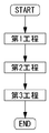
- FIG. 1 is a flowchart illustrating the flow of the method for manufacturing a functional resin body according to the present embodiment.
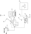
- FIG. 2 is a schematic diagram illustrating a manufacturing system used in the method for manufacturing a functional resin body according to the present embodiment.
- a functional lens is added to the lens 8, which is one of the resin bodies, to add a function of reducing the transmittance in the wavelength region of the blue region using a vapor phase transfer dyeing method.
- the technology of the present disclosure can be applied to the lens 8 regardless of the refractive index.
- the technology of the present disclosure can be applied to lenses having various refractive indexes (for example, low diopter, high diopter, 0 diopter, and the like).
- the techniques exemplified below include resin bodies other than the lens 8 (for example, goggles, cell phone covers, light covers, accessories, toys, films (for example, having a thickness of 400 ⁇ m or less), and plate materials (for example, thicknesses).
- the substrate for function addition 1 exemplified below can also be used in a transfer dyeing process other than the vapor phase transfer dyeing.
- a first step, a second step, and a third step are performed.
- the method for manufacturing a functional resin body according to the present embodiment is performed in the order of a first step, a second step, and a third step.
- the first step is a step of applying a functional dye to a base (for example, the base 2) to obtain a base for adding a function (for example, the base 1 for adding a function).
- the function applied to the function-adding substrate is obtained by heating the function-adding substrate by facing the function-adding substrate obtained in the first step with a resin body (for example, the lens 8).
- the third step is a step of fixing the functional dye to the resin body by heating the resin body to which the functional dye has been attached in the second step.
- the functional dye is a merocyanine-based functional dye that absorbs light in the blue region.
- the method for producing a functional resin body includes, when performing the above process, using the above functional dye, the luminous transmittance is 75% or more, and the average in the blue wavelength region. A function of reducing the transmittance to 10% or less is added to the resin body.
- the method for manufacturing a functional resin body according to the present disclosure includes applying a functional dye having a sublimation property to a merocyanine-based functional dye that absorbs light in a blue region.
- a first step of obtaining a substrate for adding a function a second step of attaching a functional dye to the resin body, and a third step of fixing the functional dye to the resin body.
- a function is added to the resin body such that the luminous transmittance is 75% or more and the average transmittance in the wavelength region of the blue region is 10% or less.
- a resin body having a function of having a luminous transmittance of 75% or more and an average transmittance of 10% or less in a wavelength region of a blue region can be manufactured. That is, for example, a function in which the luminous transmittance is easily 75% or more in a short time and the average transmittance in the blue wavelength region is 10% or less without requiring a complicated process or many processes. Can be produced. Since the luminous transmittance exceeds 75%, the luminous transmittance can be used as a resin body for night operation (for example, a lens for night operation), and the transmittance in the blue wavelength region is reduced. The obtained resin body can be obtained.
- a functional dye can be applied to a substrate, and the functional dye applied to the substrate can be attached to the resin body, so that the functional dye can be used for adding functions to the resin body without waste. That is, it is possible to add a function to the resin body with a smaller number of functional dyes.
- the dye for reducing the transmittance in the wavelength region of the blue region is expensive, the technology of the present disclosure is more useful.
- the luminous transmittance is calculated by the following equation (see JIS T 7331: 2006).
- S ( ⁇ ) indicates the spectral distribution of standard light used for displaying colors.
- y ( ⁇ ) indicates a color matching function in the XYZ color system.
- T ( ⁇ ) indicates the spectral solid angle transmittance.
- the luminous transmittance ( ⁇ V) is obtained by multiplying the distribution of the standard light source D65 by the relative luminosity function in the wavelength range of 380 nm to 780 nm as a denominator, and using a resin body (for example, a lens). Is calculated by multiplying the luminous flux incident through the luminous flux by the relative luminosity function, and multiplying the numerator by 100.
- the luminous transmittance of the resin body is 75% or more, the criterion relating to the luminous transmittance when the resin body is used for night driving can be satisfied.
- an average transmittance of 10% or less indicates that the average value of the transmittance for each wavelength in the blue wavelength region is 10% or less.
- the wavelength range of 380 nm to 500 nm which is generally the wavelength range of the blue region, is taken as an example of the wavelength range of the blue region. That is, in the present embodiment, for example, an average transmittance of 10% or less indicates that the average value of the transmittance at each wavelength in the wavelength range of 380 nm to 500 nm is 10% or less.
- an average transmittance of 10% or less refers to an average wavelength range of 380 nm to 500 nm even if the transmittance of 410 nm to 430 nm, which is the wavelength range of the blue region, exceeds 10%. In the case where the average value of the transmittance at each wavelength is calculated, it may be 10% or less.
- the functional dye a functional dye capable of absorbing light in a blue wavelength range and having a luminous transmittance of 75% or more is used.
- a functional dye (having a maximum absorption peak at 473 nm) that absorbs light in a wavelength region of 400 nm to 500 nm as a wavelength region of a blue region is used.
- the functional dye that absorbs light in the wavelength region of the blue region is not limited to the wavelength region of 400 nm to 500 nm, and an arbitrary wavelength region in the wavelength region of the blue region can be set. it can.
- a functional dye that absorbs light in a specific wavelength range for example, 430 nm to 500 nm
- a wavelength range of 380 nm to 500 nm which is generally a wavelength range of a blue region
- a functional dye that absorbs light in a specific wavelength range for example, 430 nm to 500 nm
- a wavelength range of 380 nm to 500 nm which is generally a wavelength range of a blue region
- a merocyanine-based dye is used as the functional dye that absorbs light in the wavelength region of the blue region.
- the functional dye that absorbs light in the wavelength region of the blue region is not limited to the dye described above, and has a sublimation property and can absorb light in the wavelength region of the blue region. Any functional dye having a function of achieving a ratio of 75% or more may be used.
- At least one functional dye may be used as the functional dye. That is, for example, in the present embodiment, in addition to the merocyanine-based functional dye that absorbs light in the blue region, a function of reducing the transmittance of light in a specific wavelength range is added to the functional resin body. You may make it. In this case, for example, only a merocyanine-based functional dye that absorbs light in the blue region may be used. For example, in this case, in addition to a merocyanine-based functional dye that absorbs light in the blue region, at least one or more functional dyes (for example, one functional dye, two functional dyes, A natural dye, four functional dyes, etc.).
- the first step may be configured to simultaneously apply the plurality of functional dyes to the substrate. Further, for example, when a plurality of functional dyes are used for a resin body, the first step may be configured to apply the plurality of functional dyes to the base at different timings.
- a polycarbonate resin for example, diethylene glycol bisallyl carbonate polymer (CR-39)), a polyurethane resin (Tribex), an allyl resin (for example, allyl diglycol carbonate and its copolymer) Coalesced, diallyl phthalate and copolymers thereof), fumaric acid-based resin (eg, benzyl fumarate copolymer), styrene-based resin, polymethyl acrylate-based resin, fiber-based resin (eg, cellulose propionate), thiourethane
- a function can be added to a resin body made of at least one of a high refractive material such as a resin or thioepoxy, a nylon resin (a polyamide resin), and the like.
- the resin body may be coated with a receiving film on which the functional dye is easily fixed. By coating the resin body with the receiving film, it becomes possible to add functions more easily.
- a sublimable dye for adjusting the color may be used in addition to the functional dye.
- a yellow dye may be used as the sublimable dye.
- a quinophthalone-based functional dye may be used as the yellow dye.
- a function-adding base may be obtained by further applying a sublimable dye, which is a yellow dye for dyeing a resin body and has a sublimation property.
- the sublimable dye applied to the function adding substrate may be sublimated, and the sublimable dye may be attached to the resin body.
- the sublimable dye may be fixed to the resin body by heating the resin body to which the sublimable dye is attached in the second step.
- a function that the luminous transmittance is 75% or more and the transmittance in the entire wavelength region in the blue wavelength region is 15% or less may be added to the resin body. That is, by adding a dye for adjusting the color, it is possible to change the transmittance in a predetermined wavelength range (for example, the transmittance in a blue wavelength range). That is, by adding the sublimable dye for adjusting the color, the transmittance in a predetermined wavelength range (for example, the transmittance in the blue wavelength range) can be finely adjusted by affecting the sublimable dye.
- a yellow dye for dyeing a resin body using a sublimable dye having sublimability and a functional dye, having a luminous transmittance of 75% or more and all wavelengths in a blue wavelength region.
- a function of reducing the transmittance of the region to 10% or less may be added to the resin body.
- the transmittance can be uniformly reduced in the entire wavelength region in the blue wavelength region. That is, if the light has a wavelength peak in the wavelength region of the blue region, the transmittance can be satisfactorily reduced. That is, even when various lights having different wavelength peaks are irradiated, the transmittance can be satisfactorily reduced for each light.
- the luminous transmittance is 75% or more, and the blue region is used.
- the first step may be configured to simultaneously apply the functional dye and the sublimable dye to the substrate.
- the first step may be configured to apply the functional dye and the sublimable dye to the substrate at different timings.
- the sublimable dye another sublimable dye may be used in addition to the yellow dye.
- the sublimable dye may further include at least one of a red dye and a blue dye.
- a function can be added and an arbitrary color can be added, so that a functional resin body dyed in a desired color can be easily obtained.
- colors other than the above three colors may be used. For example, a mixed color (green, purple, etc.) dye may be used.
- the manufacturing system 100 is used to perform each step in the method for manufacturing a functional resin body.
- a schematic configuration of the manufacturing system 100 according to the present embodiment will be described with reference to FIG.
- the manufacturing system 100 of the present embodiment includes a dye coating device 10, a vapor deposition device 30, and a dye fixing device (fixing device) 50.
- the dye coating device 10 is used.
- the dye coating apparatus 10 applies a functional dye deposited on a resin body (the lens 8 in the present embodiment) to the base 2 to obtain the function adding base 1 coated with the functional dye.
- the vapor deposition device 30 is used.
- the vapor deposition apparatus 30 causes the functional dye to be sublimated by applying the functional dye to the resin body by heating the functional additive base by facing the functional base 1 to the resin body.
- the fixing device 50 is used.
- the fixing device 50 is used for fixing the functional dye to the resin body by heating the resin body to which the functional dye is attached.
- a functional dye is applied to the substrate 2 by the dye application device 10 to obtain the function-added substrate 1 (manufacture).
- the dye coating device 10 forms the dye portion 6 by attaching a functional dye to be deposited on the lens 8 to the base 2 later.
- the base 2 is a medium that temporarily holds a functional dye used for dyeing the lens 8. The detailed description of the base 2 will be described later.
- a printing device is used as the dye application device 10.
- a dyeing ink containing a functional dye is printed on the base 2 using a printing apparatus, thereby obtaining the function-added base 1.
- This makes it easy to control the amount of the functional dye to be applied with high accuracy, so that the functional dye can be easily and uniformly applied to the substrate 2.
- the number of functional dyes used can be reduced.
- the step of drying the ink printed by the printing apparatus is performed, so that the functional dye is held more firmly.
- a sublimable dye for adjusting the color of a functional resin body is used in addition to the functional dye.
- the functional dye may be used.
- at least one of red, blue, and yellow dyes is used as the sublimable dye.
- the functional resin body can be satisfactorily dyed in various colors. That is, it is possible to easily obtain the function-adding substrate 1 that can satisfactorily dye the functional resin body with various colors.
- colors other than these three colors may be used. For example, a mixed color (green, purple, etc.) may be used.
- the functional dye may be dissolved in a solvent of the ink.
- the ink for adding a function is put into an ink container (for example, an ink pack, an ink cartridge, or the like) for an ink jet printer, and the ink container is mounted on the mounting portion 14 of the ink jet printer 11.
- an ink container for example, an ink pack, an ink cartridge, or the like
- the ink container is mounted on the mounting portion 14 of the ink jet printer 11.
- the ink cartridge 13 is used as an ink container will be described as an example.
- the ink for adding a function is put into an ink cartridge 13 for an ink jet printer, and the cartridge 13 is mounted on a mounting portion 14 of the ink jet printer 11.
- a functional dye that reduces the transmittance of light in a blue wavelength region is used as the functional dye.
- a sublimable dye is used together with the functional dye.
- the sublimable dye may be dissolved in a solvent of the ink, for example, similarly to the ink for adding a function.
- the dyeing ink has at least one of red, blue, and yellow dyeing inks.
- the dyeing ink is put into an ink container (for example, an ink pack, an ink cartridge, or the like) for an ink jet printer, and the ink container is mounted on the mounting portion 14 of the ink jet printer 11.
- an ink container for example, an ink pack, an ink cartridge, or the like
- the dyeing ink is put into each of the ink cartridges 13 for the ink jet printer, and the cartridge 13 is mounted on the mounting portion 14 of the ink jet printer 11.
- a commercially available inkjet printer 11 can be used.
- the sublimable dye a dye having heat resistance enough to withstand heat during sublimation is preferably used.
- a quinophthalone-based sublimable dye or an anthraquinone-based sublimable dye is used. Tachi).
- a configuration in which the function-adding ink and the dyeing ink are placed in separate ink ink containers is taken as an example, but is not limited thereto. Not done.
- a mixed ink obtained by mixing a function adding ink and a dyeing ink may be used.
- the mixed ink may be put in the ink container.
- the injection printer 11 for example, a case where the injection printer 11 is used as a printing device will be described as an example.
- the functional dye is applied to the base 2 by printing using the inkjet printer 11.
- the injection printer 11 includes a mounting unit 14, an inkjet head 15, and a control unit (control unit) 16.
- the injection printer 11 is not limited to the above configuration.
- the mounting unit 14 includes an ink container for a function-adding ink containing a functional dye (for example, an ink cartridge 13 described later) and an ink container for a dyeing ink containing a sublimable dye (for example, an ink described later). And the cartridge 13).
- the inkjet head 15 discharges the function-adding ink and the dyeing ink toward the base 2 from the ink container for the function-adding ink and the ink container for the dyeing ink provided in the mounting unit 14.
- the control unit 16 controls the driving of the inkjet heads 15 so that the function-adding ink and the dyeing ink are ejected independently from the respective inkjet heads 15.
- the control unit 16 discharges the function-adding ink and the dyeing ink from the inkjet head 15 at the same time, and the functional dye and the sublimable dye are discharged.
- “simultaneously” means that the functional dye and the sublimable dye can be applied to the substrate 2 in a mixed state, and includes substantially simultaneously.
- the control unit 16 discharges the function-adding ink and the dyeing ink from the inkjet head 15 at different timings so that the functional dye and the sublimable ink are discharged.
- a dye may be applied to the substrate 2.
- one of the function adding ink and the dyeing ink may be ejected first, and then the other may be ejected thereafter.
- a dyeing ink containing a functional dye for adding a function of reducing the transmittance of light in a blue wavelength range, and a sublimable dye for adjusting the color In order to print the dye ink containing the dye on the base 2, the discharge amount of each dye ink to be printed is adjusted using a personal computer 12 (hereinafter referred to as PC).
- PC personal computer 12
- the amount of the function-adding ink containing the functional dye and the amount of the dye ink containing the sublimable dye for adjusting the color are stored in the memory 20 as color data.
- the color density is stored in the memory 20 as the color data. For example, when an operator selects desired color data, it is possible to call up the color data from the memory 20 and add the same function and reproduce the same color as many times as necessary. Further, for example, since the shading of colors is digitally managed, a color having the same density can be obtained as many times as necessary. Note that, for example, the concentration gradient can be obtained by a gradation function provided in draw software or the like.
- a gradation according to a preference may be set in advance, and may be stored in the PC 12 as original gradation data (color data).
- original gradation data color data
- a gradation pattern having a density gradient will be described as an example of a desired color, but the present invention is not limited to this.
- the desired color various designs (for example, a single color design, an image, etc.) can be printed.
- the concentration of the functional dye may be changeable.
- the transmittance of light can be changed by changing the concentration of the functional dye.
- the concentration of the functional dye may be selectable, and color data for applying the functional dye at the selected concentration may be selected for each concentration of the functional dye.
- the substrate 2 on which the functional dye is printed by a printing apparatus may be a configuration using paper, a metal plate (for example, aluminum, iron, copper, or the like), glass, or the like.
- the base 2 will be described using paper as an example.
- a sheet-shaped base is used as the base 2.
- the printing apparatus will be described by taking the injection printer 11 as an example.
- the substrate 2 is inserted into the injection printer 11, and the operation of the PC 12 is performed to add the functions set in advance, and to print the respective inks so as to obtain the color and the color density.
- the printing device may be configured to apply a functional dye to the base 2 by printing using a laser printer.
- the functional dye is attached to the base 2 by using a toner and a laser printer.
- the configuration in which the functional dye is applied to the base 2 using the printing device as the dye attaching portion 10 is described as an example, but the present invention is not limited to this.
- the dye coating device 10 may have any configuration as long as the functional dye can be coated on the base 2.
- the dye application device 10 may cause the ink for function addition to adhere to the base for function addition 1 by driving a dispenser (liquid metering device), a roller, or the like.
- the function adding ink may be applied to the function adding base 1 by a worker using a brush, a roller, a spray, or the like. In addition, you may make it apply
- the functional dye When the functional dye is applied to the substrate 2, the functional dye may be applied at least once or more.
- the functional dye may be applied to the base 2 by one application (for example, one printing), or the functional dye may be applied by a plurality of applications (for example, multiple printing). It may be applied to the base 2. That is, the number of times the functional dye is applied to the substrate 2 may be changed depending on the color and the density.
- the functional dye a functional dye capable of absorbing light in a blue wavelength region and having a luminous transmittance of 75% or more is used.
- a functional dye (having a maximum absorption peak at 473 nm) that absorbs light in a wavelength region of 400 nm to 500 nm as a wavelength region of a blue region is used.
- the functional dye that absorbs light in the wavelength region of the blue region is not limited to the wavelength region of 400 nm to 500 nm, and an arbitrary wavelength region in the wavelength region of the blue region can be set. it can.
- a functional dye that absorbs light in a specific wavelength range for example, 430 nm to 500 nm
- a wavelength range of 380 nm to 500 nm which is generally a wavelength range of a blue region
- a functional dye that absorbs light in a specific wavelength range for example, 430 nm to 500 nm
- a wavelength range of 380 nm to 500 nm which is generally a wavelength range of a blue region
- a merocyanine-based dye is used as the functional dye that absorbs light in the wavelength region of the blue region.
- the functional dye that absorbs light in the wavelength region of the blue region is not limited to the dye described above, and has a sublimation property and can absorb light in the wavelength region of the blue region. Any functional dye having a function of achieving a ratio of 75% or more may be used.
- the function-adding substrate 1 on which the functional dye is applied is obtained by the inkjet printer 11.
- the second step is performed using the function-adding substrate 1 obtained in the first step.
- the function-adding base 1 obtained in the first step is made to face a resin body (in the present embodiment, the lens 8), and the function-adding base 1 is heated.
- the functional dye and the sublimable dye applied to the substrate 1 are sublimated, and the functional dye and the sublimable dye are attached to the lens 8.
- the vapor deposition device 30 is used.
- the vapor deposition device 30 sublimates the functional dye and the sublimable dye toward the functional lens 8 by heating the functional dye and the sublimable dye attached to the function-adding substrate 1 with electromagnetic waves. As a result, the functional dye and the sublimable dye are deposited on the functional lens 8.
- the functional lens 8 may be formed with various layers such as a receptor film for facilitating fixing of a functional dye and a sublimable dye in a third step described later.
- the vapor deposition device 30 of the present embodiment includes an electromagnetic wave generator 31, a vapor deposition jig 32, a pump 36, and a valve 37.
- the configuration of the vapor deposition device 30 is not limited to the above configuration. In the present embodiment, the case where the functional dye and the sublimable dye are vapor-deposited on the functional lens 8 will be described as an example, but the case where only the functional dye is vapor-deposited on the functional lens 8 will be described. Good.
- the electromagnetic wave generator 31 generates an electromagnetic wave.
- a halogen lamp that generates infrared rays is used as the electromagnetic wave generator 31.
- the electromagnetic wave generator 31 may be any unit that generates an electromagnetic wave. Therefore, in place of the halogen lamp, a configuration for generating electromagnetic waves of other wavelengths such as ultraviolet rays and microwaves may be used.
- the vapor deposition device 30 can raise the temperature of the functional dye in a short time by irradiating the base for function addition 1 with electromagnetic waves.
- the vapor deposition device 30 of the present embodiment can uniformly heat the functional dye and the sublimable dye by the electromagnetic waves from the electromagnetic wave generator 31 that is separated from the function-adding base 1.
- the jig for vapor deposition 32 holds the base for function addition 1 and the lens 8.
- the vapor deposition jig 32 of the present embodiment includes a lens support 33 and a base support 34.
- the lens support 33 includes a cylindrical base and a mounting table arranged inside the base.
- the lens 8 is supported by the mounting table of the lens support 33 while being surrounded by the base.
- the base support 34 is located at the upper end of the cylindrical base and supports the function-adding base 1 above the lens 8.
- a plate-shaped glass is further placed on the upper surface of the function-adding substrate 1 held by the substrate supporting portion 34, so that the sublimated functional dye is placed.
- the sublimation dye may be prevented from spreading to the back side of the function-adding substrate 1.
- the function-adding substrate 1 is arranged such that the surface to which the functional dye and the sublimable dye are attached faces the functional lens 8.
- the base for function addition 1 since the base for function addition 1 is supported above the function lens 8, the base for function addition 1 is placed on the base support part 34 so that the dye-adhering surface faces downward.
- the function-adding base 1 and the lens 8 when they are opposed to each other, they may be opposed in a non-contact manner (for example, 2 mm to 30 mm).
- the function-adding base 1 obtained in the first step is applied to the function-adding base 1 by heating the function-adding base 1 by facing the lens 8 in a non-contact manner.
- the functional dye and the sublimable dye thus obtained may be sublimated, and the functional dye and the sublimable dye may be attached to the lens 8.
- by opposing the substrate in a non-contact manner it is possible to suppress the conduction of heat when the substrate is heated to sublimate the functional dye and the sublimable dye to the resin body. Thereby, it is possible to suppress the resin body from being discolored, contracted, or the like due to heat.
- the functional dye and the sublimable dye can be sufficiently dispersed and adhered to the resin body. it can. As a result, variation in light transmittance and color unevenness in the resin body can be further suppressed, and a dyed resin body with good functions can be manufactured.
- the gradation pattern when a gradation pattern is applied to the substrate in the color of the resin body, the gradation pattern can be preferably reproduced on the resin body.
- the function-adding base 1 and the lens 8 are opposed to each other, they may be opposed to each other in a state where they are in contact with each other.
- the pump 36 discharges the gas inside the vapor deposition device 30 to the outside, and lowers the pressure inside the vapor deposition device 30. That is, for example, the pump 36 discharges the gas inside the vapor deposition device 30 to the outside, and makes the inside of the vapor deposition device 30 a predetermined degree of vacuum.
- the inside of the vapor deposition device 30 is set to a predetermined degree of vacuum by the pump 36 to perform the attaching operation.
- the inside of the vapor deposition device 30 is set to a predetermined vacuum state.
- the present invention is not limited to this. It is also possible to perform the attachment operation inside the vapor deposition device 30 under normal pressure.
- the function-adding base 1 is heated from above using the electromagnetic wave generator 31 to sublimate the functional dye and the sublimable dye.
- the heating temperature is lower than 100 ° C. on the function-adding substrate 1, the functional dye and the sublimable dye are difficult to sublimate from the function-adding substrate 1.
- the heating temperature is preferably between 100 and 250 ° C., but it is preferable to select the highest possible temperature according to the material of the lens 8.
- the second step may be a step of performing at least one evaporation.
- the vapor deposition may be repeated a plurality of times (for example, twice) by using a plurality of function-adding bases 1.
- Such a method is useful, for example, when the amount of dye to be applied to the resin body is large, or when a plurality of types (for example, five types) of dyes are used.
- ⁇ Third step> For example, when the second step is completed, the third step is performed.
- the third step will be described.
- the lens 8 to which the functional dye and the sublimable dye are attached in the second step is heated to fix the functional dye and the sublimable dye.
- the functional dye may be fixed.
- the dye fixing device 50 fixes the functional dye and the sublimable dye to the lens 8 by heating the lens 8 on which the functional dye and the sublimable dye are deposited. For example, when the lens 8 is heated, the functional dye and the sublimable dye are fixed to the lens 8. Thus, the function of reducing the transmittance of light in a specific wavelength range is added to the lens 8 and the color of the lens 8 can be adjusted.
- an oven is used as the dye fixing device 50. If an oven (especially a blow-type constant temperature incubator) is used, the temperature of the lens 8 gradually increases over a long period of time, so that a temperature difference hardly occurs. Therefore, the functional dye and the sublimable dye are easily fixed to the lens 8 uniformly.
- the functional dye and the sublimable dye may be fixed by heating under normal pressure.
- the third step may be performed under a different atmospheric pressure.
- the worker attaches the functional dye and the sublimable dye to the lens 8 in the vapor deposition device 30 and then takes out the lens 8 to which the functional dye and the sublimable dye are attached.
- an operator puts the lens 8 into the dye fixing device 50 and heats it under normal pressure to fix the functional dye and the sublimable dye.
- the heating is performed at a temperature at which the lens 8 is not deformed and sufficient color can be formed.
- the heating temperature may be preferably 110 ° C. or more and 160 ° C. or less (110 ° C. to 160 ° C.).
- the resin body to which the functional dye and the sublimable dye are attached in the second step is heated at a temperature of 110 ° C. to 160 ° C. May be fixed.
- the functional dye and the sublimable dye can easily reach the inside of the resin body (the lens 8 in the present embodiment).
- a function of reducing the transmittance of light in a specific wavelength range can be satisfactorily added, and dyeing can be performed more favorably.
- color omission from the dyed (color-adjusted) resin body (the lens 8 in the present embodiment) can be suppressed.
- by fixing the functional dye and the sublimable dye at a temperature of 160 ° C. or lower in the third step it is possible to prevent the resin body from being excessively heated, and it is more difficult to deform the resin body. can do.
- the above-mentioned temperature is described as a temperature at which the deformation of the resin body is difficult, but the temperature is not limited to this. For example, in the case of a resin body having high heat resistance, deformation can be made difficult even when fixing is performed at a higher temperature according to the resin body.
- the heating temperature is more preferably 120 ° C. or more and 155 ° C. or less.
- the functional dye and the sublimable dye are heated by heating the resin body to which the functional dye and the sublimable dye are attached in the second step at a temperature of 120 ° C. to 155 ° C. May be fixed.
- a function of reducing the transmittance of light in a specific wavelength range can be satisfactorily added.
- Dyeing can be performed.
- color loss from the dyed resin body can be further suppressed, and deformation of the resin body can be further suppressed.
- the method for manufacturing a functional resin body according to the present disclosure includes applying a functional dye having a sublimation property to a base, which is a merocyanine-based functional dye that absorbs light in a blue region.
- a first step of obtaining a substrate for adding a function a second step of attaching a functional dye to the resin body, and a third step of fixing the functional dye to the resin body.
- a function is added to the resin body such that the luminous transmittance is 75% or more and the average transmittance in the wavelength region of the blue region is 10% or less.
- a resin body having a function of having a luminous transmittance of 75% or more and an average transmittance of 10% or less in a wavelength region of a blue region can be manufactured. That is, for example, a function in which the luminous transmittance is easily 75% or more in a short time and the average transmittance in the blue wavelength region is 10% or less without requiring a complicated process or many processes. Can be produced. Since the luminous transmittance exceeds 75%, the luminous transmittance can be used as a resin body for night operation (for example, a lens for night operation), and the transmittance in the blue wavelength region is reduced. The obtained resin body can be obtained.
- a functional dye can be applied to a substrate, and the functional dye applied to the substrate can be attached to the resin body, so that the functional dye can be used for adding functions to the resin body without waste. That is, it is possible to add a function to the resin body with a smaller number of functional dyes.
- the dye for reducing the transmittance in the wavelength region of the blue region is expensive, the technology of the present disclosure is more useful.
- the shape (printing shape) of the dye portion 6 is circular, but is not limited thereto, and may be, for example, a semicircular shape or another shape (for example, square shape). Good.
- the method for heating the function-adding substrate 1 is described as being performed from above, but is not limited thereto.
- the functional dye can be similarly sublimated by heating from the side or from below.
- the structure of the dye fixing device 50 can be changed.
- the dye fixing device 50 may heat the lens 8 by scanning a laser on the lens 8.
- the dye fixing device 50 can intentionally generate a temperature difference according to the position of the lens 8.
- the dye fixing device 50 may control laser scanning in accordance with a target gradation state, for example, in a case where gradation dyeing or a functional dye is applied in a gradation form.
- the dye fixing device 50 may control laser scanning according to the thickness of the lens 8 or the like so that the temperature of each part of the lens 8 becomes a desired temperature.
- the dye fixing device 50 may heat the lens by directly irradiating the lens 8 with an electromagnetic wave.
- two or more of the steps (for example, the first step, the second step, the third step, etc.) performed in each of the dye coating apparatus 10, the vapor deposition apparatus 30, and the dye fixing apparatus 50 are performed by one apparatus. May be done.
- a dyeing apparatus that performs both the second step performed by the vapor deposition device 30 and the third step performed by the dye fixing device 50 may be used.
- the same heating means for example, an infrared heater or the like
- the dyeing apparatus may automatically perform a plurality of steps (for example, from the second step to the third step) in a series of flows.
- the transmittance of light in a specific wavelength region may not be reduced uniformly. There is. Therefore, for example, the region where the functional dye is applied may be different from the region where the other dye is applied.
- the functional dye may be fixed to the entire resin body, and another dye different from the functional dye may be fixed to a part of the resin body.
- the functional resin body may be further coated (for example, a hard coat, an antireflection coat, an antifouling coat, and the like).
- a specific function of the functional resin body may be improved by performing coating.
- Comparative Example 1 a functional dye was immersed in a resin body using a dip dyeing method to obtain a functional resin body.
- Comparative Examples 2 to 4 a sublimable dye was adhered to the resin body without using a functional dye, and the resin body having the sublimable dye adhered to the surface was heated. was fixed on a resin body to obtain a dyed resin body.
- Comparative Examples 5 to 7 coating treatment was performed on the dyed resin bodies obtained in Comparative Examples 2 to 4 to obtain coated dyed resin bodies. The wavelength transmittances of the functional resin bodies and the dyed resin bodies obtained in the experimental examples and the comparative examples were evaluated.
- a functional dye capable of absorbing light in the wavelength range of 430 nm to 500 nm was used as the wavelength range of the blue region.
- a dyeing ink used for a printer is prepared.
- the functional dye FDB-006 ink (Yamada Chemical Industry Co., Ltd.), which is a merocyanine dye capable of absorbing light in the wavelength range of 430 nm to 500 nm, was used.
- a functional dye, pure water, and a dispersant were placed in a container, and sufficiently stirred to produce a dyeing ink.
- Demol MS Karl MS (Kao Corporation) was used as a dispersant.
- the composition ratio of the dye, the dispersant, and pure water was 6.0% by weight of the dye, 2.5% by weight of the dispersant, and 91.5% by weight of pure water.
- the amount of the functional dye is preferably 0.1 to 20% by weight, more preferably 0.5 to 10% by weight.
- the amount of the functional dye is not limited to the above-mentioned weight%, and can be used in any amount.
- the amount of the functional dye is less than 0.1% by weight, the dye is difficult to fix, and a desired concentration may not be obtained. If the amount of the functional dye exceeds 20% by weight, the dispersibility of the functional dye may be deteriorated.
- the functional dye to be used does not decompose by heat and must have heat resistance. In this experimental example, the amount of the functional dye was 6.0% by weight.
- the container containing the dyeing ink After thoroughly dispersing the dispersant to disperse the functional dye, place the container containing the dyeing ink in the container containing water for cooling, and perform the treatment for the specified time with an ultrasonic homogenizer to obtain the functional dye. To the desired particle size. Thereafter, the dyeing ink is suction-filtered with a filter having a pore size of about 1 ⁇ m (glass fiber filter paper GF / B) to remove particles having a large particle size and dust. Thereafter, pure water is added and adjusted so as to have a designated ink concentration, and if necessary, a humectant and a surfactant for adjusting surface tension are added to prepare a function-adding ink. Although an ultrasonic homogenizer was used for dispersing this time, a micronizing device such as a bead mill may be used. In this way, a function-adding ink is manufactured.
- a filter having a pore size of about 1 ⁇ m glass fiber filter paper GF
- the inside of the ink cartridge for the (EPSON @ PX-6250S) function-adding ink of the printer was thoroughly washed, and then the prepared function-adding ink containing the functional dye was charged and set in the printer. After repeating the cleaning many times, it was confirmed that the ink was switched, and the printing software TTS-PS2 (Nidek Co., Ltd.) was applied to a substrate (high quality PPC paper) with a paper thickness of 100 ⁇ m and a black back surface.
- ⁇ Dyeing was performed using the thus obtained substrate for adding functions.
- the function-imparting substrate was attached to a dyeing jig in a vapor deposition apparatus (NTM-TTM-1000), and a functional dye was vapor-deposited on the MR8 lens (S-0.00).
- the distance between the stained surface side of the MR8 lens and the substrate for adding functions was 15 mm.
- the pressure in the vapor deposition apparatus was reduced to 60 Pa by a pump
- the surface temperature of the substrate for function addition was heated to 200 ° C. by a heating unit (a halogen lamp was used in this experimental example).
- the temperature near the substrate for function addition was measured by a temperature sensor (not shown), and when the temperature reached 200 ° C., the power of the halogen lamp was turned off, and the functional dye was sublimated and adhered.
- the luminous transmittance was calculated by calculating the transmittance in the wavelength region of 380 to 780 nm in the blue region, and substituting the calculated transmittance in each wavelength region into Equation 1 above.
- Luminous transmittance is 75% or more: ⁇ Luminous transmittance is greater than 75%: ⁇ [Evaluation of relative visibility decay rate Q value for signal light recognition (see JIS T 7330)] It has Q value for all signal light of red signal light, yellow signal light, green signal light and blue signal light: ⁇ Q value for all signal light of red signal light, yellow signal light, green signal light and blue signal light Not: ⁇ ⁇ Experimental example 2>
- a yellow sublimable dye for adjusting the color was prepared, and the function was added to the MR8 lens in the same manner as in Experimental Example 1, except that the function was added and the color was adjusted.
- a substrate for adding functions was manufactured.
- a function was added to the MR8 lens using the manufactured substrate for adding function, and the same evaluation as in Experimental Example 1 was performed. Table 1 shows the above results.
- Example 5 A function was added to the MR8 lens and evaluation was performed in the same manner as in Experimental Example 2 except that a coating process was performed on the functional MR8 lens obtained by adding a function to the MR8 lens.
- a hard coat film and an anti-reflection film were formed on the manufactured functional MR8 lens to complete a functional MR8 lens with a coating.
- the hard coat film was formed by applying a silicone-based thermosetting hard coat liquid by an immersion method, and then heating.
- the antireflection film is deposited by a vacuum deposition method at a degree of vacuum of 1.0 ⁇ 10 ⁇ 3 Pa or less and an internal temperature of the deposition machine of 70 ° C.
- a SiO2 film was formed on the second layer at 60 nm, a ZrO2 film was formed on the third layer at 120 nm, a SiO2 film was formed on the fourth layer at 110 nm, and the four layers were formed as an antireflection film. After completing the coated functional MR8 lens, the same evaluation as in Experimental Example 1 was performed. Table 1 shows the results.
- Example 6 A functional MR8 lens was coated in the same manner as in Experimental Example 5 except that the functional MR8 lens to which the function was added was replaced with the functional MR8 lens manufactured in Experimental Example 3, and the same evaluation as in Experimental Example 1 was performed. . Table 1 shows the results.
- Example 7 A functional MR8 lens was coated in the same manner as in Experimental Example 5 except that the functional MR8 lens to which the function was added was replaced with the functional MR8 lens manufactured in Experimental Example 4, and the same evaluation as in Experimental Example 1 was performed. Table 1 shows the results.
- a functional MR8 lens was produced by a conventional dip dyeing method. 60 g of FDB-006 (Yamada Chemical Industry Co., Ltd.), 30 g of Demol MS (Kao Corporation), and 3 g of Succinol (Senka Corporation) are placed in a 1 L stainless steel beaker, and then 60 g of water at about 70 ° C. is added. Stir well until homogeneously mixed.
- a function-adding solution having a concentration of FDB-006 of 0.6%.
- the concentration is a function-adding liquid having a concentration about twice as high as the concentration of the dye used in the conventional permeation method.
- the liquid for function addition in a stainless beaker was maintained at 95 ° C. while stirring in a water bath, and the function was added by immersing the MR8 lens and leaving it for 60 minutes.
- the average transmittance of light in the blue wavelength range from 380 nm to 500 nm is 10% or less.
- the transmittance is 75% or more, a function that hardly transmits light in the wavelength region of the blue region can be added, so that it was confirmed that a resin body having a higher function could be provided. .
- the luminous transmittance is 75% or more, and It was confirmed that a function of providing a transmittance of 5% or less for each wavelength of 410 nm to 430 nm in the blue wavelength region could be added to the resin body. That is, by using a yellow dye, the wavelength range from 410 nm to 430 nm was higher when the yellow dye was not added, as compared with the transmittance in the other blue region. Also, it was confirmed that the transmittance in Example 2 was able to be reduced to the same level as the transmittance in the wavelength region of the other blue region.
- this resin body has light having a wavelength peak in the wavelength region of the blue region, it is possible to satisfactorily reduce the transmittance for almost all wavelengths and obtain a more effective resin body. It was shown that it could be done. That is, the resin body can satisfactorily reduce the transmittance for each light even in the case of irradiating various lights having different wavelength peaks in the wavelength region of almost the entire blue region. It has been shown.
- the average transmittance in the wavelength region of the blue region of 380 nm to 500 nm was obtained. Can be set to 5% or less, and the transmittance can be reduced more effectively. Further, as shown in Experimental Examples 2 to 7 in Table 1, the average transmittance in the wavelength range of 400 nm to 490 nm can be set to 1% or less, and the transmittance can be more effectively reduced. it can.
Landscapes
- Engineering & Computer Science (AREA)
- Physics & Mathematics (AREA)
- Chemical & Material Sciences (AREA)
- Ophthalmology & Optometry (AREA)
- Health & Medical Sciences (AREA)
- General Physics & Mathematics (AREA)
- Optics & Photonics (AREA)
- Mechanical Engineering (AREA)
- Manufacturing & Machinery (AREA)
- Life Sciences & Earth Sciences (AREA)
- Materials Engineering (AREA)
- Wood Science & Technology (AREA)
- Organic Chemistry (AREA)
- General Health & Medical Sciences (AREA)
- Chemical Kinetics & Catalysis (AREA)
- General Chemical & Material Sciences (AREA)
- Eyeglasses (AREA)
- Optical Filters (AREA)
- Inks, Pencil-Leads, Or Crayons (AREA)
Abstract
L'invention concerne un procédé de production de corps en résine fonctionnelle qui réduit la transmittance à travers un corps en résine de la plage de longueurs d'onde dans la région bleue. Le procédé comprend : une première étape de revêtement sur un corps de base par un colorant fonctionnel, qui peut se sublimer et est un colorant fonctionnel à base de mérocyanine qui absorbe la lumière dans la région bleue, pour obtenir un corps de base avec ajout de fonction ; une deuxième étape de mise en contact d'un corps de résine face à face avec le corps de base avec ajout de fonction obtenu par la première étape, et de chauffage du corps de base avec ajout de fonction, ce qui permet de sublimer le colorant fonctionnel et de faire adhérer le colorant fonctionnel sur le corps en résine ; et une troisième étape de chauffage du corps en résine sur lequel le colorant fonctionnel a adhéré par la deuxième étape, ce qui permet de fixer le colorant fonctionnel sur le corps en résine. Le procédé ajoute au corps de résine une fonction permettant une transmittance dans le visible à 75 % ou plus, et permettant une transmittance moyenne dans la plage de longueur d'onde de la région bleue inférieure ou égale à 10 %.
Priority Applications (1)
| Application Number | Priority Date | Filing Date | Title |
|---|---|---|---|
| JP2020536343A JP7306396B2 (ja) | 2018-08-10 | 2019-05-28 | 機能樹脂体の製造方法 |
Applications Claiming Priority (2)
| Application Number | Priority Date | Filing Date | Title |
|---|---|---|---|
| JP2018150983 | 2018-08-10 | ||
| JP2018-150983 | 2018-08-10 |
Publications (1)
| Publication Number | Publication Date |
|---|---|
| WO2020031469A1 true WO2020031469A1 (fr) | 2020-02-13 |
Family
ID=69415493
Family Applications (1)
| Application Number | Title | Priority Date | Filing Date |
|---|---|---|---|
| PCT/JP2019/021145 Ceased WO2020031469A1 (fr) | 2018-08-10 | 2019-05-28 | Procédé de production de corps en résine fonctionnelle |
Country Status (2)
| Country | Link |
|---|---|
| JP (1) | JP7306396B2 (fr) |
| WO (1) | WO2020031469A1 (fr) |
Cited By (2)
| Publication number | Priority date | Publication date | Assignee | Title |
|---|---|---|---|---|
| WO2022163295A1 (fr) * | 2021-01-29 | 2022-08-04 | 株式会社ニデック | Système de teinture |
| WO2025254231A1 (fr) * | 2024-06-04 | 2025-12-11 | 배석만 | Milieu de transport de lumière de type fibre ayant une lentille formée in situ, et son procédé de fabrication |
Citations (7)
| Publication number | Priority date | Publication date | Assignee | Title |
|---|---|---|---|---|
| JP2002258004A (ja) * | 2001-03-06 | 2002-09-11 | Nidek Co Ltd | プラスチックレンズの染色用インク及び該インクを用いたプラスチックレンズの染色方法。 |
| JP2004121435A (ja) * | 2002-09-30 | 2004-04-22 | Nidek Co Ltd | 眼内レンズの着色方法及び該方法にて得られる着色眼内レンズ |
| JP2011064954A (ja) * | 2009-09-17 | 2011-03-31 | Hoya Corp | 染色プラスチックレンズの製造方法 |
| JP2013205522A (ja) * | 2012-03-27 | 2013-10-07 | Hoya Corp | プラスチックレンズの昇華染色方法 |
| JP2015118122A (ja) * | 2013-12-16 | 2015-06-25 | 東海光学株式会社 | 眼鏡レンズ及び眼鏡 |
| JP2017502352A (ja) * | 2013-12-23 | 2017-01-19 | エシロル アンテルナショナル(コンパーニュ ジェネラル ドプテーク) | 無色外観を有する透明光学物品 |
| WO2017171075A1 (fr) * | 2016-03-31 | 2017-10-05 | ホヤ レンズ タイランド リミテッド | Verre de lunettes et lunettes |
Family Cites Families (1)
| Publication number | Priority date | Publication date | Assignee | Title |
|---|---|---|---|---|
| US9813338B2 (en) * | 2015-12-10 | 2017-11-07 | Cisco Technology, Inc. | Co-existence of routable and non-routable RDMA solutions on the same network interface |
-
2019
- 2019-05-28 WO PCT/JP2019/021145 patent/WO2020031469A1/fr not_active Ceased
- 2019-05-28 JP JP2020536343A patent/JP7306396B2/ja active Active
Patent Citations (7)
| Publication number | Priority date | Publication date | Assignee | Title |
|---|---|---|---|---|
| JP2002258004A (ja) * | 2001-03-06 | 2002-09-11 | Nidek Co Ltd | プラスチックレンズの染色用インク及び該インクを用いたプラスチックレンズの染色方法。 |
| JP2004121435A (ja) * | 2002-09-30 | 2004-04-22 | Nidek Co Ltd | 眼内レンズの着色方法及び該方法にて得られる着色眼内レンズ |
| JP2011064954A (ja) * | 2009-09-17 | 2011-03-31 | Hoya Corp | 染色プラスチックレンズの製造方法 |
| JP2013205522A (ja) * | 2012-03-27 | 2013-10-07 | Hoya Corp | プラスチックレンズの昇華染色方法 |
| JP2015118122A (ja) * | 2013-12-16 | 2015-06-25 | 東海光学株式会社 | 眼鏡レンズ及び眼鏡 |
| JP2017502352A (ja) * | 2013-12-23 | 2017-01-19 | エシロル アンテルナショナル(コンパーニュ ジェネラル ドプテーク) | 無色外観を有する透明光学物品 |
| WO2017171075A1 (fr) * | 2016-03-31 | 2017-10-05 | ホヤ レンズ タイランド リミテッド | Verre de lunettes et lunettes |
Cited By (4)
| Publication number | Priority date | Publication date | Assignee | Title |
|---|---|---|---|---|
| WO2022163295A1 (fr) * | 2021-01-29 | 2022-08-04 | 株式会社ニデック | Système de teinture |
| JPWO2022163295A1 (fr) * | 2021-01-29 | 2022-08-04 | ||
| EP4286581A4 (fr) * | 2021-01-29 | 2024-12-18 | Nidek Co., Ltd. | Système de teinture |
| WO2025254231A1 (fr) * | 2024-06-04 | 2025-12-11 | 배석만 | Milieu de transport de lumière de type fibre ayant une lentille formée in situ, et son procédé de fabrication |
Also Published As
| Publication number | Publication date |
|---|---|
| JPWO2020031469A1 (ja) | 2021-08-26 |
| JP7306396B2 (ja) | 2023-07-11 |
Similar Documents
| Publication | Publication Date | Title |
|---|---|---|
| JP2001214386A (ja) | プラスチックレンズの染色方法及び染色用基体 | |
| JP6999273B2 (ja) | 染色装置及び染色方法 | |
| JP7306396B2 (ja) | 機能樹脂体の製造方法 | |
| US20020148053A1 (en) | Method of dyeing a plastic lens, a plastic lens obtained by use of the dyeing method, and a dyeing system, a dyeing device, and a dyeing jig for a plastic lens | |
| JP4421176B2 (ja) | プラスチックレンズの染色方法、染色装置及び染色レンズ | |
| EP3461945B1 (fr) | Procédé de teinture et procédé de fabrication d'un corps de base pour teinture | |
| WO2002071108A1 (fr) | Encre de coloration de lentille plastique et procede de coloration de lentille plastique utilisant cette encre | |
| JP7404866B2 (ja) | 染色偏光レンズの製造方法 | |
| JP4365060B2 (ja) | プラスチックレンズ染色方法及び該方法に用いるプラスチックレンズ染色用インク | |
| JP2001159746A (ja) | プラスチックレンズ染色方法及び染色レンズ | |
| WO2019167388A1 (fr) | Procédé de fabrication d'un corps en résine coloré fonctionnel | |
| JP4268767B2 (ja) | プラスチックレンズの染色方法 | |
| EP3761081B1 (fr) | Procédé de fabrication d'un corps en résine multifonctionnelle | |
| US11623419B2 (en) | Method of producing photochromic resin body and method of producing function-adding base body | |
| JP6972848B2 (ja) | 染色方法及び染色用基体の製造方法 | |
| JP4068310B2 (ja) | 紫外線吸収効果を有するプラスチックレンズの製造方法及び該方法に使用する紫外線吸収用インク | |
| EP2868484B1 (fr) | Objet de base donneur de colorant, méthode de fabrication d'un corps de résine coloré et méthode de fabrication d'un objet de base donneur de colorant | |
| JP2004121434A (ja) | 眼内レンズの着色方法及び該方法にて得られる着色眼内レンズ | |
| JP6977452B2 (ja) | 印刷装置及びキャリア剤インクのインク容器 | |
| JP2019059205A (ja) | キャリア剤インク |
Legal Events
| Date | Code | Title | Description |
|---|---|---|---|
| 121 | Ep: the epo has been informed by wipo that ep was designated in this application |
Ref document number: 19847093 Country of ref document: EP Kind code of ref document: A1 |
|
| ENP | Entry into the national phase |
Ref document number: 2020536343 Country of ref document: JP Kind code of ref document: A |
|
| NENP | Non-entry into the national phase |
Ref country code: DE |
|
| 122 | Ep: pct application non-entry in european phase |
Ref document number: 19847093 Country of ref document: EP Kind code of ref document: A1 |