WO2020031471A1 - Dispositif d'évaluation, procédé d'évaluation et programme d'évaluation - Google Patents
Dispositif d'évaluation, procédé d'évaluation et programme d'évaluation Download PDFInfo
- Publication number
- WO2020031471A1 WO2020031471A1 PCT/JP2019/021401 JP2019021401W WO2020031471A1 WO 2020031471 A1 WO2020031471 A1 WO 2020031471A1 JP 2019021401 W JP2019021401 W JP 2019021401W WO 2020031471 A1 WO2020031471 A1 WO 2020031471A1
- Authority
- WO
- WIPO (PCT)
- Prior art keywords
- display
- data
- display screen
- subject
- gazing point
- Prior art date
- Legal status (The legal status is an assumption and is not a legal conclusion. Google has not performed a legal analysis and makes no representation as to the accuracy of the status listed.)
- Ceased
Links
- RPZUBXWEQBPUJR-UHFFFAOYSA-N C(C1)C2C1CCCC2 Chemical compound C(C1)C2C1CCCC2 RPZUBXWEQBPUJR-UHFFFAOYSA-N 0.000 description 1
Images













Classifications
-
- A—HUMAN NECESSITIES
- A61—MEDICAL OR VETERINARY SCIENCE; HYGIENE
- A61B—DIAGNOSIS; SURGERY; IDENTIFICATION
- A61B10/00—Instruments for taking body samples for diagnostic purposes; Other methods or instruments for diagnosis, e.g. for vaccination diagnosis, sex determination or ovulation-period determination; Throat striking implements
-
- A—HUMAN NECESSITIES
- A61—MEDICAL OR VETERINARY SCIENCE; HYGIENE
- A61B—DIAGNOSIS; SURGERY; IDENTIFICATION
- A61B3/00—Apparatus for testing the eyes; Instruments for examining the eyes
- A61B3/10—Objective types, i.e. instruments for examining the eyes independent of the patients' perceptions or reactions
- A61B3/113—Objective types, i.e. instruments for examining the eyes independent of the patients' perceptions or reactions for determining or recording eye movement
-
- A—HUMAN NECESSITIES
- A61—MEDICAL OR VETERINARY SCIENCE; HYGIENE
- A61B—DIAGNOSIS; SURGERY; IDENTIFICATION
- A61B5/00—Measuring for diagnostic purposes; Identification of persons
- A61B5/16—Devices for psychotechnics; Testing reaction times ; Devices for evaluating the psychological state
Definitions
- the present invention relates to an evaluation device, an evaluation method, and an evaluation program.
- Patent Literature 1 since the test subject selects an answer by operating the touch panel or the like, it is difficult to perform verification including contingency, and it is difficult to obtain high evaluation accuracy. Therefore, it has been required to accurately evaluate cognitive dysfunction and brain dysfunction.
- the present invention has been made in view of the above, and an object of the present invention is to provide an evaluation device, an evaluation method, and an evaluation program capable of accurately evaluating cognitive dysfunction and cerebral dysfunction.
- An evaluation device includes a display screen, a gazing point detection unit that detects a position of a gazing point of a subject who observes the display screen, and a first display that displays question information to be a question for the subject on the display screen. Operation, a second display operation of displaying a guidance target that guides the subject's gazing point to a target position on the display screen, and a plurality of response objects serving as answers to the question after the second display operation are displayed.
- a display control unit that performs a display operation including: a third display operation that is arranged and displayed at a position that does not overlap with the guidance position of the display screen; and a specific area corresponding to a specific target object among the plurality of answer target objects; An area setting unit configured to set a comparison area corresponding to a comparison target object different from the specific target object; and determining the fixation point during the display period in which the third display operation is performed based on the position of the fixation point.
- Area and A determining unit that determines whether or not the point is present in the comparison area, based on a determination result in the determining unit, a calculating unit that calculates gazing point data in the display period, and based on the gazing point data, An evaluation unit for obtaining evaluation data of the subject.
- the evaluation method includes displaying an image on a display screen, detecting a position of a gazing point of a subject observing the display screen, and displaying question information serving as a question for the subject on the display screen.
- a first display operation, a second display operation of displaying a guidance target that guides the subject's gazing point to a target position on the display screen, and a plurality of answer targets serving as answers to the question after the second display operation Performing a display operation including a third display operation of arranging and displaying an object at a position that does not overlap with the guidance position of the display screen, and a specific area corresponding to a specific object among the plurality of answer objects.
- a comparison area corresponding to a comparison object different from the specific object, and based on the position of the point of interest, the point of interest is set to the specific area during a display period in which the third display operation is performed. as well as Determining whether or not the subject exists in the comparison area; calculating gazing point data in the display period based on the determination result; and obtaining evaluation data of the subject based on the gazing point data.
- the evaluation program includes a process of displaying an image on a display screen, a process of detecting a position of a gazing point of a subject observing the display screen, and displaying question information serving as a question for the subject on the display screen.
- a first display operation, a second display operation of displaying a guidance target that guides the subject's gazing point to a target position on the display screen, and a plurality of answer targets serving as answers to the question after the second display operation Performing a display operation including a third display operation of arranging and displaying an object at a position that does not overlap with the guidance position of the display screen; and a specific area corresponding to the specific object among the plurality of answer objects.
- an evaluation device an evaluation method, and an evaluation program capable of accurately evaluating cognitive dysfunction and cerebral dysfunction.
- FIG. 1 is a perspective view schematically illustrating an example of a visual line detection device according to the present embodiment.
- FIG. 2 is a diagram illustrating an example of a hardware configuration of the visual line detection device according to the present embodiment.
- FIG. 3 is a functional block diagram illustrating an example of the visual line detection device according to the present embodiment.
- FIG. 4 is a schematic diagram for explaining a method of calculating the position data of the corneal curvature center according to the present embodiment.
- FIG. 5 is a schematic diagram for explaining a method of calculating the position data of the corneal curvature center according to the present embodiment.
- FIG. 6 is a schematic diagram for explaining an example of the calibration process according to the present embodiment.
- FIG. 1 is a perspective view schematically illustrating an example of a visual line detection device according to the present embodiment.
- FIG. 2 is a diagram illustrating an example of a hardware configuration of the visual line detection device according to the present embodiment.
- FIG. 3 is a functional block diagram illustrating an example of the
- FIG. 7 is a schematic diagram for explaining an example of the gazing point detection process according to the present embodiment.
- FIG. 8 is a diagram illustrating an example of the question information displayed on the display screen.
- FIG. 9 is a diagram illustrating an example of the guidance target displayed on the display screen.
- FIG. 10 is a diagram illustrating an example of the answer target displayed on the display screen.
- FIG. 11 is a diagram illustrating an example of an area set on the display screen.
- FIG. 12 is a diagram illustrating an example of the question information displayed on the display screen.
- FIG. 13 is a diagram illustrating an example of the guidance target displayed on the display screen.
- FIG. 14 is a diagram illustrating an example of the answer target displayed on the display screen.
- FIG. 15 is a diagram illustrating an example of an area set on the display screen.
- FIG. 16 is a diagram illustrating another display example of the guidance target object displayed on the display screen.
- FIG. 17 is a diagram illustrating another display example of the answer target displayed on the display screen.
- FIG. 18 is a diagram illustrating an example of the instruction information displayed on the display screen.
- FIG. 19 is a diagram illustrating an example of the question information displayed on the display screen.
- FIG. 20 is a diagram illustrating an example of the guidance target displayed on the display screen.
- FIG. 21 is a diagram illustrating an example of the answer target displayed on the display screen.
- FIG. 22 is a diagram illustrating another display example of the answer target displayed on the display screen.
- FIG. 23 is a flowchart illustrating an example of the evaluation method according to the present embodiment.
- FIG. 23 is a flowchart illustrating an example of the evaluation method according to the present embodiment.
- FIG. 24 is a diagram illustrating an example of the operation after performing the second display operation.
- FIG. 25 is a flowchart illustrating another example of the evaluation method according to the present embodiment.
- FIG. 26 is a diagram illustrating another example of the operation after the second display operation.
- FIG. 27 is a diagram illustrating an example of the answer target displayed on the display screen.
- FIG. 28 is a flowchart illustrating another example of the evaluation method according to the present embodiment.
- FIG. 29 is a diagram illustrating another example of the question information displayed on the display screen.
- FIG. 30 is a diagram illustrating another example of the question information displayed on the display screen.
- FIG. 31 is a diagram illustrating another example of the question information displayed on the display screen.
- FIG. 32 is a diagram illustrating another example of the guidance target object displayed on the display screen.
- FIG. 33 is a diagram illustrating another example of the answer target displayed on the display screen.
- FIG. 34 is a flowchart illustrating another example of the process in the first display operation.
- FIG. 35 is a flowchart illustrating another example of the processing in the first display operation and the second display operation.
- FIG. 36 is a diagram illustrating another example of the instruction information displayed on the display screen.
- FIG. 37 is a diagram illustrating another example of the question information displayed on the display screen.
- FIG. 38 is a diagram illustrating another example of the guidance target object displayed on the display screen.
- FIG. 39 is a diagram illustrating another example of the question information displayed on the display screen.
- FIG. 40 is a diagram illustrating another example of the question information displayed on the display screen.
- FIG. 41 is a diagram illustrating another example of the question information displayed on the display screen.
- FIG. 42 is a diagram illustrating another example of the guidance target displayed on the display screen.
- a three-dimensional global coordinate system is set and the positional relationship of each part is described.
- the direction parallel to the first axis of the predetermined surface is defined as the X-axis direction
- the direction parallel to the second axis of the predetermined surface orthogonal to the first axis is defined as the Y-axis direction
- a direction parallel to the third axis is defined as a Z-axis direction.
- the predetermined plane includes the XY plane.
- FIG. 1 is a perspective view schematically illustrating an example of a visual line detection device 100 according to the first embodiment.
- the gaze detection device 100 is used as an evaluation device for evaluating cognitive dysfunction and brain dysfunction.
- the visual line detection device 100 includes a display device 101, a stereo camera device 102, and a lighting device 103.
- the display device 101 includes a flat panel display such as a liquid crystal display (LCD) or an organic EL display (organic electroluminescence display: OLED).
- the display device 101 has a display screen 101S.
- the display screen 101S displays an image.
- the display screen 101S displays, for example, an index for evaluating the visual function of the subject.
- the display screen 101S is substantially parallel to the XY plane.
- the X axis direction is the horizontal direction of the display screen 101S
- the Y axis direction is the vertical direction of the display screen 101S
- the Z axis direction is the depth direction orthogonal to the display screen 101S.
- the stereo camera device 102 has a first camera 102A and a second camera 102B.
- the stereo camera device 102 is disposed below the display screen 101S of the display device 101.
- the first camera 102A and the second camera 102B are arranged in the X-axis direction.
- the first camera 102A is arranged in the ⁇ X direction with respect to the second camera 102B.
- Each of the first camera 102A and the second camera 102B includes an infrared camera, and has, for example, an optical system capable of transmitting near-infrared light having a wavelength of 850 [nm] and an image sensor capable of receiving the near-infrared light. .
- the lighting device 103 includes a first light source 103A and a second light source 103B.
- the lighting device 103 is arranged below the display screen 101S of the display device 101.
- the first light source 103A and the second light source 103B are arranged in the X-axis direction.
- the first light source 103A is arranged in the ⁇ X direction with respect to the first camera 102A.
- the second light source 103B is arranged in the + X direction more than the second camera 102B.
- Each of the first light source 103A and the second light source 103B includes an LED (light emitting diode) light source, and can emit, for example, near-infrared light having a wavelength of 850 [nm].
- the first light source 103A and the second light source 103B may be arranged between the first camera 102A and the second camera 102B.
- the illumination device 103 emits near-infrared light, which is detection light, to illuminate the eyeball 111 of the subject.
- the stereo camera device 102 captures a part of the eyeball 111 (hereinafter, referred to as “eyeball”) with the second camera 102B when the detection light emitted from the first light source 103A is applied to the eyeball 111. Then, when the detection light emitted from the second light source 103B is applied to the eyeball 111, the eyeball 111 is photographed by the first camera 102A.
- a frame synchronization signal is output from at least one of the first camera 102A and the second camera 102B.
- the first light source 103A and the second light source 103B emit detection light based on the frame synchronization signal.
- the first camera 102A captures image data of the eyeball 111 when the detection light emitted from the second light source 103B is applied to the eyeball 111.
- the second camera 102B captures image data of the eyeball 111 when the detection light emitted from the first light source 103A is applied to the eyeball 111.
- the detection light When the detection light is applied to the eyeball 111, a part of the detection light is reflected by the pupil 112, and the light from the pupil 112 enters the stereo camera device 102.
- a corneal reflection image 113 that is a virtual image of the cornea is formed on the eyeball 111, and light from the corneal reflection image 113 enters the stereo camera device 102.
- the intensity of light incident on the stereo camera device 102 from the pupil 112 decreases, and the cornea
- the intensity of light incident on the stereo camera device 102 from the reflection image 113 increases. That is, the image of the pupil 112 captured by the stereo camera device 102 has low brightness, and the image of the corneal reflection image 113 has high brightness.
- the stereo camera device 102 can detect the position of the pupil 112 and the position of the corneal reflection image 113 based on the luminance of the captured image.
- FIG. 2 is a diagram illustrating an example of a hardware configuration of the eye-gaze tracking device 100 according to the present embodiment.
- the gaze detection device 100 includes a display device 101, a stereo camera device 102, a lighting device 103, a computer system 20, an input / output interface device 30, a drive circuit 40, and an output device 50. , An input device 60.
- the computer system 20, the drive circuit 40, the output device 50, and the input device 60 perform data communication via the input / output interface device 30.
- the computer system 20 includes an arithmetic processing device 20A and a storage device 20B.
- the arithmetic processing device 20A includes a microprocessor such as a CPU (central processing unit).
- the storage device 20B includes a memory or storage such as a ROM (read only memory) and a RAM (random access memory).
- the arithmetic processing device 20A performs arithmetic processing according to the computer program 20C stored in the storage device 20B.
- the drive circuit 40 generates a drive signal and outputs the drive signal to the display device 101, the stereo camera device 102, and the lighting device 103. Further, the drive circuit 40 supplies the image data of the eyeball 111 captured by the stereo camera device 102 to the computer system 20 via the input / output interface device 30.
- the output device 50 includes a display device such as a flat panel display. Note that the output device 50 may include a printing device.
- the input device 60 generates input data when operated. Input device 60 includes a keyboard or mouse for a computer system. Note that the input device 60 may include a touch sensor provided on a display screen of the output device 50 that is a display device.
- the display device 101 and the computer system 20 are separate devices. Note that the display device 101 and the computer system 20 may be integrated.
- the tablet personal computer may include the computer system 20, the input / output interface device 30, the drive circuit 40, and the display device 101.
- FIG. 3 is a functional block diagram illustrating an example of the eye gaze detecting device 100 according to the present embodiment.
- the input / output interface device 30 has an input / output unit 302.
- the driving circuit 40 generates a driving signal for driving the display device 101 and outputs the driving signal to the display device 101, and a driving signal for driving the first camera 102A to generate a driving signal for the first camera 102A.
- the first camera input / output unit 404A supplies image data of the eyeball 111 captured by the first camera 102A to the computer system 20 via the input / output unit 302.
- the second camera input / output unit 404B supplies the image data of the eyeball 111 captured by the second camera 102B to the computer system 20 via the input / output unit 302.
- the computer system 20 controls the visual line detection device 100.
- the computer system 20 includes a display control unit 202, a light source control unit 204, an image data acquisition unit 206, an input data acquisition unit 208, a position detection unit 210, a curvature center calculation unit 212, a fixation point detection unit 214, , An area setting unit 216, a determination unit 218, a calculation unit 220, a storage unit 222, an evaluation unit 224, and an output control unit 226.
- the functions of the computer system 20 are exhibited by the arithmetic processing unit 20A and the storage device 20B.
- the display control unit 202 performs a first display operation of displaying question information, which is a question for the subject, on the display screen 101S, and a second display operation of displaying, on the display screen, a guidance target that guides the subject's gazing point to a target position. And a third display operation of arranging and displaying, after the second display operation, a plurality of answer objects serving as answers to the questions at positions not overlapping the guidance position of the display screen 101S.
- the question information includes characters, designs, and the like.
- the guidance target includes an eye-catching image or the like for guiding a gazing point to a desired position on the display screen 101S. The eye-catching video allows the subject to start watching from the target position of the evaluation image.
- the target position can be set to a position in the evaluation image at which the subject is to be watched when the display of the evaluation image is started.
- the plurality of answer objects include, for example, a specific object that is a correct answer to the question and a comparison object that is different from the specific object.
- the question information, the guidance target object, and the answer target object are included in, for example, an evaluation video or an evaluation image to be visually recognized by a subject.
- the display control unit 202 displays such an evaluation video or an evaluation image on the display screen 101S.
- the light source control unit 204 controls the light source driving unit 406 to control the operation state of the first light source 103A and the second light source 103B.
- the light source control unit 204 controls the first light source 103A and the second light source 103B such that the first light source 103A and the second light source 103B emit detection light at different timings.
- the image data acquisition unit 206 acquires image data of the subject's eye 111 taken by the stereo camera device 102 including the first camera 102A and the second camera 102B from the stereo camera device 102 via the input / output unit 302.
- the input data acquisition unit 208 acquires input data generated by operating the input device 60 from the input device 60 via the input / output unit 302.
- the position detection unit 210 detects the position data of the pupil center based on the image data of the eyeball 111 acquired by the image data acquisition unit 206. Further, the position detection unit 210 detects the position data of the corneal reflection center based on the image data of the eyeball 111 acquired by the image data acquisition unit 206.
- the pupil center is the center of the pupil 112.
- the corneal reflection center is the center of the corneal reflection image 113.
- the position detection unit 210 detects the position data of the pupil center and the position data of the corneal reflection center for each of the left and right eyeballs 111 of the subject.
- the center of curvature calculating unit 212 calculates the position data of the center of the corneal curvature of the eyeball 111 based on the image data of the eyeball 111 acquired by the image data acquiring unit 206.
- the gaze point detection unit 214 detects the position data of the gaze point of the subject based on the image data of the eyeball 111 acquired by the image data acquisition unit 206.
- the position data of the gazing point refers to position data of an intersection point between the subject's line of sight vector defined by the three-dimensional global coordinate system and the display screen 101S of the display device 101.
- the gazing point detection unit 214 detects the line-of-sight vectors of the left and right eyeballs 111 of the subject based on the pupil center position data and the corneal curvature center position data acquired from the image data of the eyeball 111. After the gaze vector is detected, the gazing point detection unit 214 detects gazing point position data indicating an intersection between the gazing vector and the display screen 101S.
- the area setting unit 216 sets a specific area corresponding to the specific object and a comparison area corresponding to each comparative object on the display screen 101S of the display device 101 during the display period in which the third display operation is performed. .
- the determination unit 218 determines whether or not the gazing point exists in the specific area and the comparison area based on the viewpoint position data during the display period in which the third display operation is performed, and outputs the determination data.
- the determination unit 218 determines, for example, at regular time intervals, whether or not the point of regard exists in the specific area and the comparison area.
- the fixed time can be, for example, the period of the frame synchronization signal output from the first camera 102A and the second camera 102B (for example, every 20 [msec]).
- Calculating section 220 calculates movement progress data indicating the progress of the movement of the gazing point during the display period (sometimes referred to as gazing point data) based on the determination data of determination section 218.
- the movement progress data includes the arrival time data from the start of the display period to the arrival point of the gaze point to the specific area for the first time, and the movement time data between the plurality of comparison areas until the gaze point first reaches the specific area.
- Movement count data indicating the number of times the position of the viewpoint moves
- existence time data indicating the existence time when the fixation point was in the specific area or the comparison area during the display period, and the fixation point during the display time in the specific area and the comparison area.
- final area data indicating the last existing area.
- the arithmetic unit 220 has a management timer that manages the playback time of the video, and a detection timer T that detects the time that has elapsed since the video was displayed on the display screen 101S.
- the arithmetic unit 220 has a counter that counts the number of times that the point of interest is determined to be present for the specific area.
- the evaluation unit 224 obtains evaluation data of the subject based on the movement progress data.
- the evaluation data is data for evaluating whether or not the subject can gaze at the specific target object displayed on the display screen 101S in the display operation.
- the storage unit 222 stores the above-described determination data, movement progress data (existing time data, movement count data, final area data, arrival time data), and evaluation data.
- the storage unit 222 displays the image on the display screen, detects the position of the gazing point of the subject observing the display screen, and displays the question information for the subject on the display screen.
- An operation, a second display operation of displaying on the display screen a guidance target that guides the subject's gazing point to the target position, and a plurality of response objects serving as answers to the questions after the second display operation are displayed on the display screen.
- a display operation including a third display operation of arranging and displaying at a position that does not overlap with a specific area of a plurality of answer objects and a comparison object different from the specific object
- the judgment result There are a process of calculating the gaze point data in the display period, on the basis of the gaze point data, and stores the evaluation program for executing a process of obtaining the evaluation data of the subject into the computer.
- the output control unit 226 outputs data to at least one of the display device 101 and the output device 50.
- the center-of-curvature calculation unit 212 calculates the position data of the center of the corneal curvature of the eyeball 111 based on the image data of the eyeball 111.
- 4 and 5 are schematic diagrams for explaining a method of calculating position data of the corneal curvature center 110 according to the present embodiment.
- FIG. 4 shows an example in which the eyeball 111 is illuminated by one light source 103C.
- FIG. 5 shows an example in which the eyeball 111 is illuminated by the first light source 103A and the second light source 103B.
- the light source 103C is arranged between the first camera 102A and the second camera 102B.
- Pupil center 112C is the center of pupil 112.
- the corneal reflection center 113C is the center of the corneal reflection image 113.
- a pupil center 112C indicates a pupil center when the eyeball 111 is illuminated by one light source 103C.
- the corneal reflection center 113C indicates a corneal reflection center when the eyeball 111 is illuminated by one light source 103C.
- the corneal reflection center 113C exists on a straight line connecting the light source 103C and the corneal curvature center 110.
- the corneal reflection center 113C is positioned at an intermediate point between the corneal surface and the corneal curvature center 110.
- the corneal curvature radius 109 is the distance between the corneal surface and the corneal curvature center 110.
- the position data of the corneal reflection center 113C is detected by the stereo camera device 102.
- the corneal curvature center 110 exists on a straight line connecting the light source 103C and the corneal reflection center 113C.
- the curvature center calculation unit 212 calculates, as the position data of the corneal curvature center 110, position data at which the distance from the corneal reflection center 113C on the straight line becomes a predetermined value.
- the predetermined value is a value determined in advance from a general radius of curvature of the cornea or the like, and is stored in the storage unit 222.
- the first camera 102A and the second light source 103B and the second camera 102B and the first light source 103A are bilaterally symmetric with respect to a straight line passing through an intermediate position between the first camera 102A and the second camera 102B. It is arranged at the position. It can be considered that the virtual light source 103V exists at an intermediate position between the first camera 102A and the second camera 102B.
- the corneal reflection center 121 indicates a corneal reflection center in an image of the eyeball 111 captured by the second camera 102B.
- the corneal reflection center 122 indicates a corneal reflection center in an image obtained by photographing the eyeball 111 with the first camera 102A.
- the corneal reflection center 124 indicates a corneal reflection center corresponding to the virtual light source 103V.
- the position data of the corneal reflection center 124 is calculated based on the position data of the corneal reflection center 121 and the position data of the corneal reflection center 122 captured by the stereo camera device 102.
- the stereo camera device 102 detects the position data of the corneal reflection center 121 and the position data of the corneal reflection center 122 in a three-dimensional local coordinate system defined by the stereo camera device 102.
- camera calibration is performed in advance by the stereo calibration method, and conversion parameters for converting the three-dimensional local coordinate system of the stereo camera device 102 into a three-dimensional global coordinate system are calculated.
- the conversion parameters are stored in the storage unit 222.
- the center-of-curvature calculation unit 212 converts the position data of the corneal reflection center 121 and the position data of the corneal reflection center 122 captured by the stereo camera device 102 into position data in a three-dimensional global coordinate system using the conversion parameters.
- the curvature center calculating unit 212 calculates the position data of the corneal reflection center 124 in the three-dimensional global coordinate system based on the position data of the corneal reflection center 121 and the position data of the corneal reflection center 122 defined in the three-dimensional global coordinate system. I do.
- the corneal curvature center 110 exists on a straight line 123 connecting the virtual light source 103V and the corneal reflection center 124.
- the center-of-curvature calculation unit 212 calculates position data at which the distance from the corneal reflection center 124 on the straight line 123 becomes a predetermined value as position data of the corneal curvature center 110.
- the predetermined value is a value determined in advance from a general radius of curvature of the cornea or the like, and is stored in the storage unit 222.
- the corneal curvature center 110 is calculated by the same method as the method in the case where there is one light source.
- the corneal curvature radius 109 is the distance between the corneal surface and the corneal curvature center 110. Accordingly, the corneal curvature radius 109 is calculated by calculating the corneal surface position data and the corneal curvature center 110 position data.
- FIG. 6 is a schematic diagram for explaining an example of the calibration process according to the present embodiment.
- a target position 130 is set to make the subject gaze.
- the target position 130 is defined in a three-dimensional global coordinate system.
- the target position 130 is set, for example, at the center position of the display screen 101S of the display device 101. Note that the target position 130 may be set at an end position of the display screen 101S.
- the output control unit 226 displays a target image at the set target position 130.
- the straight line 131 is a straight line connecting the virtual light source 103V and the corneal reflection center 113C.
- the straight line 132 is a straight line connecting the target position 130 and the pupil center 112C.
- the corneal curvature center 110 is the intersection of the straight line 131 and the straight line 132.
- the center-of-curvature calculation unit 212 calculates the position data of the corneal curvature center 110 based on the position data of the virtual light source 103V, the position data of the target position 130, the position data of the pupil center 112C, and the position data of the corneal reflection center 113C. Can be calculated.
- FIG. 7 is a schematic diagram for explaining an example of the gazing point detection process according to the present embodiment.
- a point of regard 165 indicates a point of regard obtained from the center of the corneal curvature calculated using a general curvature radius value.
- the gazing point 166 indicates a gazing point obtained from the corneal curvature center calculated using the distance 126 obtained by the calibration process.
- Pupil center 112C indicates the pupil center calculated in the calibration process
- corneal reflection center 113C indicates the corneal reflection center calculated in the calibration process.
- the straight line 173 is a straight line connecting the virtual light source 103V and the corneal reflection center 113C.
- the corneal curvature center 110 is a position of the corneal curvature center calculated from a general curvature radius value.
- the distance 126 is a distance between the pupil center 112C and the corneal curvature center 110 calculated by the calibration process.
- the corneal curvature center 110H indicates the position of the corrected corneal curvature center obtained by correcting the corneal curvature center 110 using the distance 126.
- the corneal curvature center 110H is obtained from the fact that the corneal curvature center 110 exists on the straight line 173 and that the distance between the pupil center 112C and the corneal curvature center 110 is a distance 126.
- the line of sight 177 calculated when using a general radius of curvature is corrected to the line of sight 178.
- the gazing point on the display screen 101S of the display device 101 is corrected from the gazing point 165 to the gazing point 166.
- evaluation method Next, an evaluation method according to the present embodiment will be described.
- a cognitive dysfunction and a cerebral dysfunction of a subject are evaluated by using the above-described gaze detection device 100.
- FIG. 8 is a diagram showing an example of the question information I1 displayed on the display screen 101S in the evaluation method according to the present embodiment.
- the display control unit 202 displays question information I1 as a question for the subject on the display screen 101S as a first display operation.
- the question information I1 is a question to gaze at a correct symbol as a development of the cube.
- the display control unit 202 displays, for example, character information I1a such as a sentence and symbol information I1b such as a symbol as the question information I1, but is not limited thereto, and may include only the character information I1a.
- FIG. 9 is a diagram illustrating an example of the guidance target E1 displayed on the display screen 101S.
- the display control unit 202 performs eye catching on the image of the guidance target E1 in which the question information I1 is reduced toward the predetermined target position P1 in the display screen 101S.
- the image is displayed on the display screen 101S as an image.
- the center position of the display screen 101S is set as the target position P1, but the present invention is not limited to this.
- the display control unit 202 displays an object different from the question information I1 on the display screen 101S as a guidance target in a state where the question information I1 is displayed on the display screen 101S, and displays the object on the display screen 101S.
- An image reduced toward the target position P1 may be displayed on the display screen 101S as an eye catching image.
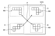
- FIG. 10 is a diagram showing an example of the answer target displayed on the display screen 101S.
- the display control unit 202 displays, as a third display operation, a pattern in which six squares are connected as a plurality of answer objects M1 to M4 on the display screen. Displayed on 101S.
- the display control unit 202 determines, as the plurality of answer objects M1 to M4, a specific object M1 that is correct for the question information I1, and an incorrect answer for the question information I1 unlike the specific object M1.
- the comparison objects M2 to M4 are displayed on the display screen 101S.
- the display control unit 202 arranges the plurality of answer objects M1 to M4 at positions not overlapping each other. Further, the display control unit 202 arranges the plurality of answer objects M1 to M4 at positions not overlapping with the guidance position. For example, the display control unit 202 arranges a plurality of answer objects M1 to M4 around the guidance position.
- the guidance position is a target position P1 at which the target of interest is guided by the guidance target E1.
- the display control unit 202 can arrange the plurality of answer objects M1 to M4 at positions equidistant from the target position P1, which is the guidance position.
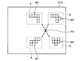
- FIG. 11 is a diagram illustrating an example of an area set on the display screen 101S during a display period in which the third display operation is performed.
- the area setting unit 216 sets a specific area A corresponding to the specific target M1.
- the area setting unit 216 sets comparison areas BD corresponding to the comparison objects M2 to M4, respectively.
- the area setting unit 216 can set the specific area A in an area including at least a part of the specific target object M1.
- the region setting unit 216 can set comparison regions B to D in regions including at least a part of the comparison objects M2 to M4, respectively.
- the area setting unit 216 sets the specific area A and the comparison areas BD to positions that do not overlap each other. Note that the specific area A and the comparison areas BD are not displayed on the display screen 101S.
- FIG. 11 shows an example of the gazing point P displayed as a result after measurement, for example, on the display screen 101S, but the gazing point P is not actually displayed on the display screen 101S.
- the detection of the gazing point position data is performed, for example, at the cycle of the frame synchronization signal output from the first camera 102A and the second camera 102B (for example, every 20 [msec]).
- the first camera 102A and the second camera 102B capture images synchronously.
- the area setting unit 216 sets the specific area A in a rectangular range including the specific target M1 that is correct for the question information I1. Similarly, the area setting unit 216 sets the comparison areas B to D in rectangular ranges including the comparison objects M2 to M4 which are incorrect for the question information I1.
- the shapes of the specific region A and the comparison regions BD are not limited to a rectangle, but may be other shapes such as a circle, an ellipse, and a polygon.
- Symptoms of cognitive dysfunction and brain dysfunction are known to affect the cognitive ability of the subject. If the subject is not a cognitive dysfunction or a cerebral dysfunction, it is determined that a square cannot be assembled by looking at each of the comparison objects M2 to M4 displayed on the display screen 101S in the third display operation. Specifically, it is possible to find and gaze at the specific target M1. When the subject has cognitive dysfunction and cerebral dysfunction, the above-described assembly may not be performed, and the specific target M1 may not be watched. On the other hand, in the method in which the answer objects M1 to M4 are displayed on the display screen 101S, at the start of the third display operation, the gazing point of the subject may be accidentally placed on the specific object M1 that is the correct answer. In such a case, there is a possibility that the subject is determined to be correct regardless of whether the subject has a cognitive dysfunction or a cerebral dysfunction. Therefore, it is difficult to evaluate the subject with high accuracy.
- the question information I1 is displayed on the display screen 101S to have the subject confirm it.
- the guidance target is displayed on the display screen 101S, and the gazing point of the subject is guided to the target position P1.
- a plurality of answer objects M1 to M4 are displayed on the display screen 101S around the guidance position (target position P1).
- the determination unit 218 determines whether the subject's gazing point exists in the specific area A and the plurality of comparison areas BD. Outputs the judgment data.
- Calculating section 220 calculates movement progress data indicating the progress of movement of gazing point P during the display period based on the determination data.
- the arithmetic unit 220 calculates existence time data, movement count data, final area data, and arrival time data as movement progress data.
- the existence time data indicates the existence time when the point of regard P exists in the specific area A or the comparison areas BD.
- the existence time data can be the number of times that the determination unit 218 determines that the gazing point exists in the specific area A or the comparison areas BD. That is, the arithmetic unit 220 can use the count values CNTA, CNTB, CNTC, and CNTD of the counter as the existence time data.
- the number-of-movements data indicates the number of times the position of the gazing point P moves between the plurality of comparison areas BD until the gazing point P first reaches the specific area A. Accordingly, the arithmetic unit 220 counts how many times the point of regard P has moved between the specific area A and the comparison areas BD, and counts the count result until the point of regard P reaches the specific area A. Can be data.
- the final area data indicates the area where the fixation point P was present last in the display time of the specific area A and the comparison areas B to D, that is, the area where the subject was gazing last as the answer.
- the arithmetic unit 220 updates the area where the point of interest P is present each time the point of interest P is detected, so that the detection result at the end of the display period can be used as the final area data.
- the arrival time data indicates the time from the start of the display period to the arrival of the gazing point at the specific area A for the first time. Therefore, the arithmetic unit 220 measures the elapsed time from the start of the display period by the timer T, and sets the flag value to 1 when the gazing point first reaches the specific area A, and detects the measured value of the timer T. The detection result of the timer T can be used as arrival time data.
- the evaluation unit 224 obtains evaluation data based on existence time data, movement count data, final area data, and arrival time data.
- the data value of the last area data is D1
- the data value of the existence time data of the specific area A is D2
- the data value of the arrival time data is D3
- the data value of the movement count data is D4.
- the data value D1 of the final area data is 1 if the final fixation point P of the subject exists in the specific area A (that is, if the answer is correct), and if it does not exist in the specific area A (that is, , 0 if incorrect).
- the data value D2 of the existence time data is the number of seconds during which the point of interest P exists in the specific area A. Note that the data value D2 may have an upper limit value of the number of seconds shorter than the display period.
- the data value D3 of the arrival time data is the reciprocal of the arrival time (for example, 1 / (arrival time) / 10) (10: the minimum arrival time is 0.1 second and the arrival time evaluation value is 1 or less). Coefficient).
- the counter value is used as it is as the data value D4 of the movement count data. Note that the data value D4 may be appropriately provided with an upper limit.
- K1 to K4 are constants for weighting.
- the constants K1 to K4 can be set as appropriate.
- the evaluation value ANS expressed by the above equation is obtained when the data value D1 of the final area data is 1, the data value D2 of the existence time data is large, the data value D3 of the arrival time data is small, When the value of the value D4 is large, the value becomes large. That is, the final gazing point P exists in the specific area A, the existence time of the gazing point P in the specific area A is long, the arrival time at which the gazing point P reaches the specific area A from the start of the display period is short, The evaluation value ANS increases as the number of times the gazing point P moves in each area increases.
- the data value D1 of the final area data is 0, the data value D2 of the existence time data is small, the data value D3 of the arrival time data is large, and the data value D4 of the movement count data is If smaller, the value will be smaller. That is, the final gazing point P does not exist in the specific area A, the existence time of the gazing point P in the specific area A is short, and the arrival time at which the gazing point P reaches the specific area A from the start of the display period is long. The smaller the number of times that the gazing point P moves in each area, the smaller the evaluation value ANS.
- the evaluation unit 224 can obtain evaluation data by determining whether the evaluation value ANS is equal to or greater than a predetermined value. For example, when the evaluation value ANS is equal to or more than a predetermined value, it can be evaluated that the subject is unlikely to have a cognitive dysfunction and a cerebral dysfunction. When the evaluation value ANS is less than the predetermined value, it can be evaluated that the subject is highly likely to have cognitive dysfunction and cerebral dysfunction.
- the evaluation unit 224 may determine the subject's evaluation value based on at least one of the above-mentioned gazing point data. For example, if the existence time data CNTA of the specific area A is equal to or more than a predetermined value, the evaluation unit 224 can evaluate that the subject is less likely to be a person with cognitive dysfunction and cerebral dysfunction. Further, the evaluation unit 224 may perform the evaluation using the existence time data CNTB, CNTC, and CNTD of the comparison areas BD.
- the evaluation unit 224 determines, for example, the ratio of the total time of the existence time data CNTA of the specific area A and the existence time data CNTB, CNTC, and CNTD of the comparison areas BD (the gaze rates of the specific area A and the comparison areas BD). If the ratio is equal to or more than the predetermined value, it can be evaluated that the subject is unlikely to be a person with cognitive dysfunction and cerebral dysfunction. Further, if the ratio between the existence time data CNTA of the specific region A and the entire gaze time (the ratio of the gaze time of the specific region A to the total gaze time) is equal to or greater than a predetermined value, the evaluation unit 224 determines that the subject In addition, it can be evaluated that the possibility of being a cerebral dysfunction person is low.
- the evaluation unit 224 determines that if the final region is the specific region A, the subject is less likely to be a person with cognitive dysfunction and cerebral dysfunction. It can be evaluated that there is a high possibility that the subject is a person with a disability and brain dysfunction.
- ⁇ Evaluation section 224 can store the value of evaluation value ANS in storage section 222.
- an evaluation value ANS for the same subject may be cumulatively stored, and an evaluation may be performed when the evaluation value ANS is compared with a past evaluation value. For example, when the evaluation value ANS becomes higher than the past evaluation value, it can be evaluated that the brain function is improved compared to the previous evaluation. When the cumulative value of the evaluation value ANS is gradually increased, it is possible to evaluate that the brain function is gradually improved.
- the evaluation unit 224 may evaluate the existence time data, the number of times of movement, the final area data, and the arrival time data individually or in combination. For example, when the gazing point P accidentally reaches the specific area A while viewing many objects, the data value D4 of the number-of-movements data becomes small. In this case, the evaluation can be performed in combination with the data value D2 of the existence time data described above. For example, when the existence time is long even when the number of times of movement is small, it can be evaluated that the specific area A which is the correct answer can be watched. Further, when the number of movements is small and the existence time is short, it can be evaluated that there is a case where the gazing point P accidentally passes through the specific area A.
- the gazing point has reached the correct specific area A with little movement of the gazing point.
- the number of times of movement is small, if the final area is not the specific area A, it can be evaluated that, for example, the gazing point P has accidentally passed the specific area A.
- the output control unit 226 when the evaluation unit 224 outputs the evaluation data, the output control unit 226 responds to the evaluation data, for example, “It is considered that the subject is less likely to have cognitive dysfunction and brain dysfunction.” And the character data of "the subject is likely to have cognitive dysfunction and brain dysfunction" can be output to the output device 50.
- the output control unit 226 When the evaluation value ANS for the same subject is higher than the past evaluation value ANS, the output control unit 226 outputs character data such as “improved brain function” to the output device 50. Can be output.
- FIG. 12 is a diagram showing an example of the question information I2 displayed on the display screen 101S.
- the display control unit 202 displays question information I2 including character information I2a and symbol information I2b on the display screen 101S.
- the question information I2 is a question that determines the number of triangles present in the symbol shown as symbol information I2b and pays attention to the correct numerical value.
- the display control unit 202 displays both the character information I2a and the symbol information I2b as the question information I2.
- FIG. 13 is a diagram illustrating an example of the guidance target E2 displayed on the display screen 101S.
- the display control unit 202 sets, as an eye-catching image, an image of the guidance target E2 in which only the symbol information I2b of the question information I2 is reduced toward the target position P1. It is displayed on the display screen 101S.
- the display control unit 202 can use a part of the question information I2 as the guidance target E2.
- FIG. 14 is a diagram showing an example of the answer target displayed on the display screen 101S.
- the display control unit 202 displays a plurality of answer objects M5 to M8 each indicating a numerical value of “9” to “16” on the display screen 101S.
- the display control unit 202 determines, as the plurality of answer objects M5 to M8, a specific object M5 that is correct for the question information I2, and, unlike the specific object M5, is incorrect for the question information I2.
- the comparison objects M6 to M8 are displayed on the display screen 101S.
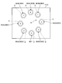
- the display control unit 202 arranges the plurality of answer objects M5 to M8 at positions that do not overlap each other. Further, the display control unit 202 arranges the plurality of answer objects M5 to M8 at positions not overlapping the guidance position. For example, the display control unit 202 arranges a plurality of answer objects M5 to M8 around a target position P1, which is a guidance position. The display control unit 202 can radially arrange the plurality of answer objects M5 to M8 at positions equidistant from the target position P1, which is the guidance position. For example, the display control unit 202 can arrange the plurality of answer objects M5 to M8 at the same pitch on the same circumference centering on the target position P1.
- FIG. 15 is a diagram showing an example of an area set on the display screen 101S during a display period in which the third display operation is performed.
- the area setting unit 216 sets a specific area A corresponding to the specific target M5.
- the region setting unit 216 sets comparison regions B to D corresponding to the comparison objects M6 to M8, respectively.
- the area setting unit 216 sets the specific area A and the comparison areas BD to positions that do not overlap each other.
- the region setting unit 216 determines, for example, a comparison target M6a indicating a difference of “14” and a comparison target M6b indicating “12” on the basis of the numerical value “13” indicated by the specific target M5 that is a correct answer. Is a comparison area B. Further, a comparison target M7a indicating two different numerical values “15” and a comparison target M7b indicating “11” are set as a comparison area C. The comparison object M8a indicating three or more different numerical values “16”, the comparison object M8b indicating “10”, and the comparison object M8c indicating “9” are referred to as a comparison area D.
- the data value D1 when the final point of gaze P of the subject does not exist in the specific area A, the data value D1 is not set to 0 but a numerical value close to the correct answer is answered.
- a fixed data value can be given in order. For example, 0.6 when the subject's final fixation point P exists in the comparison area B, 0.2 when the subject's final fixation point P exists in the comparison area C, When the final gaze point P of the subject exists in the comparison area D, the data value D1 may be obtained as 0, for example.
- FIG. 16 is a diagram showing another display example of the guidance target object E2 displayed on the display screen 101S.
- the display control unit 202 may set the target position P1a at a position shifted from the center of the display screen 101S.
- the display control unit 202 displays, on the display screen 101S, an image of the guidance target E2 in which only the symbol information I2b of the question information I2 is reduced toward the target position P1a as an eye-catching image. indicate.
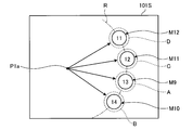
- FIG. 17 is a diagram illustrating another display example of the answer target displayed on the display screen 101S.
- the display control unit 202 displays a plurality of answer objects M9 to M12 on the display screen 101S as a third display operation.
- the display control unit 202 determines, as the plurality of answer targets M9 to M12, a specific target M9 that is correct for the question information I2, and, unlike the specific target M9, is incorrect for the question information I2.
- the comparison objects M10 to M12 are displayed on the display screen 101S.
- the display control unit 202 arranges the plurality of answer objects M9 to M12 at positions that do not overlap each other, as described above. Further, the display control unit 202 arranges the plurality of answer objects M9 to M12 at positions not overlapping the guidance position. For example, the display control unit 202 arranges a plurality of answer objects M9 to M12 around a target position P1a that is a guidance position. The display control unit 202 can arrange the plurality of answer objects M9 to M12 at positions that are equidistant from the target position P1a that is the guidance position. For example, the display control unit 202 can arrange the plurality of answer objects M9 to M12 at equal pitches on an arc R centered on the target position P1a. Further, as shown in FIG.
- the area setting unit 216 sets the specific area A corresponding to the specific target M9. Further, the region setting unit 216 sets comparison regions B to D corresponding to the comparison objects M10 to M12, respectively. In this case, the area setting unit 216 sets the specific area A and the comparison areas BD to positions that do not overlap each other.
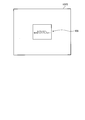
- FIG. 18 is a diagram showing an example of the instruction information displayed on the display screen 101S.
- the display control unit 202 can display instruction information I3 for instructing the subject to store the information that is the premise of the question information.
- the instruction information I3 includes image information I3b indicating a person's face and character information I3a instructing to store the person's face indicated by the image information I3b.
- FIG. 19 is a diagram showing an example of the question information displayed on the display screen 101S.
- the display control unit 202 displays question information I4 for the subject as a first display operation.
- the question information I4 is a question that the user looks at the same person as the face of the person indicated by the image information I3b.
- the question information I4 includes character information I4a indicating the content of the question and image information I4b which is the same image as the image information I3b.
- FIG. 20 is a diagram illustrating an example of the guidance target object E3 displayed on the display screen 101S.
- the display control unit 202 sets, as the eye-catching image, an image of the guidance target E3 in which only the image information I4b of the question information I4 is reduced toward the target position P1. It is displayed on the display screen 101S.
- the display control unit 202 can use a part of the question information I4 as the guidance target E3.
- FIG. 21 is a diagram showing an example of the answer target displayed on the display screen 101S.
- the display control unit 202 displays a plurality of answer objects M13 to M16 each showing a face image of a different person on the display screen 101S.
- the display control unit 202 determines, as the plurality of answer targets M13 to M16, a specific target M13 that is correct for the question information I4, and, unlike the specific target M13, is incorrect for the question information I4.
- the comparison objects M14 to M16 are displayed on the display screen 101S.
- the correct image of the specific target M13 is the same image as the image information I3b and the image information I4b.
- the display control unit 202 arranges the plurality of answer objects M13 to M16 at positions not overlapping each other. Further, the display control unit 202 arranges the plurality of answer objects M13 to M16 at positions not overlapping with the guidance position. For example, the display control unit 202 arranges a plurality of answer objects M13 to M16 around the guidance position.
- the guidance position is a target position P1 for guiding the gazing point of the subject by the guidance target E3.
- the display control unit 202 can arrange the plurality of answer objects M13 to M16 at positions that are equidistant from the target position P1, which is the guidance position.
- FIG. 21 also shows an example of an area set on the display screen 101S during the display period in which the third display operation is performed.
- the area setting unit 216 sets a specific area A corresponding to the specific target M13.
- the region setting unit 216 sets comparison regions BD corresponding to the comparison objects M14 to M16, respectively.
- the area setting unit 216 sets the specific area A and the comparison areas BD to positions that do not overlap each other.
- Symptoms of cognitive and brain dysfunctions are known to affect memory.
- the subject is not a cognitive dysfunction or a cerebral dysfunction, he looks at each of the comparison objects M14 to M16 displayed on the display screen 101S in the third display operation, and looks at the image information I4b stored in the first display operation. After comparing with the person, it is determined that they are not the same, and finally, the specific target M13 can be found and watched.
- the specific object M13 may not be memorized or may be immediately forgotten even if memorized. Therefore, the above-mentioned comparison cannot be performed, and the specific target M13 may not be watched.
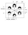
- FIG. 22 is a diagram showing another display example of the answer target displayed on the display screen 101S.
- the display control unit 202 can radially arrange a plurality of answer objects M17 to M20 at positions equidistant from the target position P1, which is a guidance position.
- the display control unit 202 can arrange the plurality of answer objects M17 to M20 at the same pitch on the same circumference centering on the target position P1.
- FIG. 22 also shows an example of a region set on the display screen 101S during a display period in which the third display operation is performed.
- the area setting unit 216 sets a specific area A corresponding to the specific target M17.
- the region setting unit 216 determines, for example, the comparison target B with respect to the comparison target object M18 whose gender is the same female as the specific target object M17. I do.
- a comparison target M19 whose gender is male but whose expressions are relatively common in expression such as eyebrows and nose shape is set as a comparison area C.
- the comparison target M20 (M20a to M20c) whose gender is male and whose expression has little in common is set as a comparison area D.
- the area setting unit 216 sets the specific area A and the comparison areas BD to positions that do not overlap each other.
- the data value D1 when the final point of gaze P of the subject does not exist in the specific area A, the data value D1 is not set to 0 but a numerical value close to the correct answer is answered.
- a fixed data value can be given in order. For example, 0.6 when the subject's final fixation point P exists in the comparison area B, 0.2 when the subject's final fixation point P exists in the comparison area C, When the final gaze point P of the subject exists in the comparison area D, the data value D1 may be obtained as 0, for example.
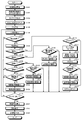
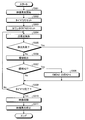
- FIG. 23 is a flowchart illustrating an example of the evaluation method according to the present embodiment.
- the display control unit 202 starts playback of a video (Step S101). After the elapse of the waiting time up to the evaluation video portion (step S102), the timer T is reset (step S103), the count value CNTA of the counter is reset (step S104), and the flag value is set to 0 (step S105). .
- the gaze point detection unit 214 detects the gaze point of the subject on the display screen 101S of the display apparatus 101 at a predetermined sampling cycle (for example, 20 [msec]) in a state where the video displayed on the display device 101 is shown to the subject.
- Position data is detected (step S106).
- the determination unit 218 determines an area where the point of regard P exists based on the position data (Step S108). If the position data is not detected (Yes in step S107), the process from step S130 described later is performed.
- the calculating unit 220 determines whether or not the flag value is 1, that is, the gazing point P has reached the specific area A. It is determined whether it is the first time (1: reached, 0: not reached) (step S110). When the flag value is 1 (Yes in step S110), the arithmetic unit 220 skips the following steps S111 to S113 and performs the processing of step S114 described later.
- the calculation unit 220 uses the measurement result of the timer T as the arrival time data. It is extracted (step S111). In addition, the calculation unit 220 causes the storage unit 222 to store the number-of-movements data indicating how many times the gazing point P has moved between the regions before reaching the specific region A (step S112). After that, the calculation unit 220 changes the flag value to 1 (Step S113).
- the arithmetic unit 220 determines whether or not the region where the point of regard P exists in the latest detection, that is, the final region is the specific region A (step S114). When determining that the final area is the specific area A (Yes in step S114), the arithmetic unit 220 skips the following steps S115 and S116 and performs the processing of step S117 described later. If it is determined that the final area is not the specific area A (No in step S114), the calculation unit 220 sets the number of integrations indicating how many times the point of regard P has moved between the areas to +1 (step S115). The last area is changed to the specific area A (step S116).
- the arithmetic unit 220 sets the count value CNTA indicating the existence time data in the specific area A to +1 (step S117). After that, the arithmetic unit 220 performs the processing of step S130 and thereafter, which will be described later.
- the calculation unit 220 determines whether or not the gazing point P exists in the comparison area B (step S118). When it is determined that the gazing point P exists in the comparison area B (Yes in step S118), the calculation unit 220 determines whether or not the area where the gazing point P exists in the latest detection, that is, the final area is the comparison area B. Is determined (step S119). When determining that the final area is the comparison area B (Yes in step S119), the arithmetic unit 220 skips the following steps S120 and S121 and performs the processing of step S130 described later.
- step S119 If it is determined that the final region is not the comparison region B (No in step S119), the arithmetic unit 220 sets the number of integrations indicating how many times the point of regard P has moved between the regions to +1 (step S120). The last area is changed to the comparison area B (step S121). After that, the arithmetic unit 220 performs the processing of step S130 and thereafter, which will be described later.
- the arithmetic unit 220 determines whether or not the point of regard P exists in the comparison area C (step S122). When it is determined that the fixation point P exists in the comparison area C (Yes in step S122), the calculation unit 220 determines whether the area where the fixation point P exists in the latest detection, that is, the final area is the comparison area C. Is determined (step S123). When determining that the final area is the comparison area C (Yes in step S123), the arithmetic unit 220 skips steps S124 and S125 below and performs the processing of step S130 described later.
- step S123 If it is determined that the final area is not the comparison area C (No in step S123), the arithmetic unit 220 sets the number of times of integration indicating how many times the point of regard P has moved between the areas (step S124). The final area is changed to the comparison area C (step S125). After that, the arithmetic unit 220 performs the processing of step S130 and thereafter, which will be described later.
- the calculation unit 220 determines whether or not the gazing point P exists in the comparison area D (step S126). When it is determined that the gazing point P exists in the comparison area D (Yes in step S126), the calculation unit 220 determines whether or not the area where the gazing point P exists in the latest detection, that is, the final area is the comparison area D. Is determined (step S127). When it is determined that the gazing point P does not exist in the comparison area D (No in step S126), the processing in step S130 described later is performed.
- step S127 When determining that the final area is the comparison area D (Yes in step S127), the arithmetic unit 220 skips the following steps S128 and S129 and performs the processing of step S130 described later. If it is determined that the final area is not the comparison area D (No in step S127), the calculation unit 220 sets the number of integrations indicating how many times the point of regard P has moved between the areas to +1 (step S128). The last area is changed to the comparison area D (step S129). After that, the arithmetic unit 220 performs the processing of step S130 and thereafter, which will be described later.
- step S130 the arithmetic unit 220 determines whether or not the time to complete the reproduction of the video has reached. If the arithmetic unit 220 determines that the time to complete the reproduction of the video has not reached (No in step S130), the processing from step S106 onward is repeated.
- step S131 the evaluation unit 224 calculates the evaluation value ANS based on the existence time data, the number of times of movement, the final area data, and the arrival time data obtained from the above processing result ( Step S132), evaluation data is obtained based on the evaluation value ANS.
- the output control unit 226 outputs the evaluation data obtained by the evaluation unit 224 (Step S133).
- the evaluation apparatus includes the display screen 101S, the gazing point detection unit 214 that detects the position of the gazing point of the subject who observes the image displayed on the display screen 101S, A first display operation of displaying question information on the display screen 101S, a second display operation of displaying a guidance target for guiding the gazing point P of the subject to the predetermined target position P1, and a second display operation
- a display control unit 202 that performs a display operation including: a third display operation of arranging and displaying a plurality of answer objects serving as answers to the questions at positions not overlapping the guidance position of the display screen 101S after the An area setting unit 216 for setting a specific area A corresponding to a specific object among the objects and comparison areas BD corresponding to a comparative object different from the specific object; Then, a determination unit 218 that determines whether or not the gazing point P exists in the specific area A and the comparison areas BD during the display period in which the third display operation is performed.
- the evaluation method detects the position of the gazing point of the subject who observes the image displayed on the display screen 101S, and displays the question information as a question for the subject on the display screen 101S.
- a display operation, a second display operation of displaying a guidance target for guiding the gazing point P of the subject to the predetermined target position P1 on the display screen 101S, and a plurality of answer objects serving as answers to the questions after the second display operation Performing a display operation including a third display operation of arranging at a position that does not overlap the guidance position of the display screen 101S, and a specific area A corresponding to a specific target object among a plurality of answer target objects; Setting the comparison areas B to D corresponding to the comparison object different from the specific object, and, based on the position of the point of interest P, the point of interest P is set to the specific area A during the display period in which the third display operation is performed. as well as Determining whether or not the subject exists in the comparison areas B to D, calculating gazing
- the evaluation program includes a process of detecting a position of a gazing point of a subject observing an image displayed on the display screen 101S, and a first process of displaying question information serving as a question for the subject on the display screen 101S.
- the evaluation device 100 can evaluate the subject with high accuracy.
- the area setting unit 216 sets the specific area A and the comparison areas B to D at positions that do not overlap each other. As a result, the answer of the subject can be determined with high accuracy, and the subject can be evaluated with higher accuracy.
- the display control unit 202 arranges a plurality of answer targets at positions that are equidistant from the guidance position. As a result, chances can be further reduced, and the answer of the subject can be determined with high accuracy.
- the movement progress data includes arrival time data indicating the time from the start of the display period to the arrival of the point of interest P for the first time in the specific area A; Is the number of movements of the position of the gazing point P between the plurality of comparison areas B to D until the gazing point P first reaches the specific area A, and the gazing point P exists in the specific area A during the display period.
- the data includes at least one of the existence time data indicating the existence time, and the final area data indicating the area where the fixation point P last existed in the display time among the specific area A and the comparison areas BD.
- the evaluation unit 224 obtains evaluation data by weighting at least one piece of data included in the movement history data. By assigning priorities to the data, more accurate evaluation data can be obtained.
- FIG. 24 is a diagram showing an example of the operation after performing the second display operation.
- the determination unit 218 detects whether or not the gazing point exists in the predetermined area Q including the target position P1 after the second display operation based on the gazing point position data. The determination may be made when it is detected that Q exists.
- the predetermined area Q can be set to a range that includes the target position P1 and does not overlap the specific area A and the comparison areas B to D set in the third display operation.
- FIG. 25 is a flowchart showing another example of the evaluation method according to the present embodiment.
- FIG. 25 shows an operation of making a determination when it is detected that the point of gaze exists in the predetermined area Q.
- the display control unit 202 starts the reproduction of the video as in the above embodiment (step S101).
- the gazing point detection unit 214 displays the video displayed on the display device 101 to the subject, and sets a predetermined sampling period (for example, 20 [msec]). ).
- the position data of the gazing point of the subject on the display screen 101S of the display device 101 is detected (step S140).
- the determination unit 218 detects an area where the point of regard P exists based on the position data (Step S142).
- step S143 When it is determined that the gazing point P exists in the predetermined area Q (Yes in step S143), the timer T is reset (step S103), the count value CNTA of the counter is reset (step S104), and the flag value is set to 0. (Step S105). Then, the processing after step S106 is performed.
- the position data is not detected (Yes in step S141) and when it is determined that the gazing point P does not exist in the predetermined area Q (No in step S143), the image reproduction is stopped (step S144).
- the process after step S101 is repeatedly performed. Thereby, the gazing point P of the subject can be more reliably positioned at the target position P1 or the predetermined area Q around the target position P1.
- FIG. 26 is a diagram showing another example of the operation after the second display operation is performed.
- the gazing point detection unit 214 determines the position of the gazing point P after the second display operation, that is, the position of the gazing point P guided by the guidance target, based on the position data of the gazing point. May be required.
- the position of the gazing point P can be obtained based on, for example, the X coordinate (Px) and the Y coordinate (Py) based on the origin position (for example, the lower right corner in the drawing) of the display screen 101S.
- the fixation point detection unit 214 sets the calculated position of the fixation point P as the calculated position P2.
- FIG. 27 is a diagram illustrating an example of the answer target displayed on the display screen 101S.
- the display control unit 202 arranges a plurality of answer objects M1 to M4 around the guidance position as a third display operation.
- the guidance position is a calculated position P2 calculated after the second display operation.
- the display control unit 202 can arrange the plurality of answer objects M1 to M4 at positions that are equidistant from the calculated position P2 that is the guidance position.
- the area setting unit 216 sets the specific area A corresponding to the specific object M1 arranged as described above, and sets the comparison areas BD corresponding to the respective comparison objects M2 to M4.
- FIG. 28 is a flowchart showing another example of the evaluation method according to the present embodiment.
- FIG. 28 shows an operation of calculating the position of the gazing point P and arranging the answering objects M1 to M4 using the calculated position P2 as a guidance position.
- the display control unit 202 starts playback of a video (Step S101).
- the gazing point detection unit 214 displays the video displayed on the display device 101 to the subject and sets a prescribed sampling period (for example, 20 [msec]). ),
- the position data of the gazing point of the subject on the display screen 101S of the display device 101 is detected (step S140).
- the determination unit 218 sets the calculated position P2, which is the position of the point of regard P, based on the position data (Step S145).
- the display control unit 202 arranges a plurality of answer objects M1 to M4 around the calculation position P2 (step S146).
- the timer T is reset (step S103)
- the count value CNTA of the counter is reset (step S104)
- the flag value is set to 0 (step S105). Then, the processing after step S106 is performed.
- step S141 If no position data is detected (Yes in step S141), the video reproduction is stopped (step S144), and the processes in and after step S101 are repeatedly performed. Thereby, the positions of the plurality of answer objects M1 to M4 are set based on the positions of the gazing points P of the subject after the second display operation. The arrangement on the answer objects M1 to M4 can be suppressed more reliably.
- the evaluation device 100 is used as an evaluation device for evaluating the possibility of cognitive dysfunction and cerebral dysfunction has been described as an example.
- the present invention is not limited to this.
- the evaluation device 100 may be used as an evaluation device that evaluates a subject who does not have a cognitive dysfunction such as a developmental disorder or a cerebral dysfunction.
- the question information displayed on the display screen 101S in the first display operation is not limited to the question information in which the correct symbols and numerical values are gazed at the questions described in the above embodiment.
- the question information for example, the question may be such that the subject stores the number of symbols that meet a predetermined condition among a plurality of symbols, and causes the subject to calculate using the stored number.
- FIGS. 29 to 31 are diagrams showing examples of the question information displayed on the display screen 101S.
- the display control unit 202 displays question information I5, a plurality of apple symbols FA1 and a plurality of lemon symbols FB1 on the display screen 101S.
- the question information I5 is a question for storing the number of apple symbols FA1 by obtaining the number of apple symbols FA1 from the plurality of symbols.
- the area setting unit 216 sets a corresponding area A1 corresponding to the apple symbol FA1.
- the region setting unit 216 can set the corresponding region A1 in a region including at least a part of the apple symbol FA1.
- the display control unit 202 displays the question information I5, a plurality of apple symbols FA1 and a plurality of lemon symbols FB1 on the display screen 101S for a predetermined period.
- the gazing point detection unit 214 detects the position data of the gazing point of the subject on the display screen 101S of the display device 101 at a specified sampling period (for example, 20 [msec]) during this period.
- the determining unit 218 determines whether or not the gazing point of the subject exists in the corresponding area A1 in each sampling cycle, and outputs the determination data.
- the calculation unit 220 calculates first gaze time data indicating a gaze time for the apple symbol FA1 indicated by the question information I5 based on the determination data.
- the display control unit 202 After displaying the question information I5, the plurality of apple symbols FA1 and the plurality of lemon symbols FB1 on the display screen 101S for a predetermined period, the display control unit 202 changes the question information I6 and the plurality of bananas as shown in FIG. And a plurality of strawberry symbols FB2 are displayed on the display screen 101S.
- the question information I6 is a question for storing the number by obtaining the number of banana symbols FA2 among a plurality of symbols.
- the area setting unit 216 sets a corresponding area A2 corresponding to the banana symbol FA2.
- the region setting unit 216 can set the corresponding region A2 in a region including at least a part of the banana design FA2.
- the display control unit 202 displays the question information I6, the plurality of banana symbols FA2, and the plurality of strawberry symbols FB2 on the display screen 101S for a predetermined period.
- the gazing point detection unit 214 detects the position data of the gazing point of the subject on the display screen 101S of the display device 101 at a specified sampling period (for example, 20 [msec]) during this period.
- the determining unit 218 determines whether or not the gazing point of the subject exists in the corresponding area A2 in each sampling cycle, and outputs the determination data.
- the calculation unit 220 calculates second gaze time data indicating a gaze time for the symbol FA2 of the banana indicated by the question information I6 based on the determination data.
- the display control unit 202 After displaying the question information I6, the plurality of banana symbols FA2, and the plurality of strawberry symbols FB2 on the display screen 101S for a predetermined period, the display control unit 202 sets the question information I7 as the question information I7 as shown in FIG. A question to the effect that the subject is to calculate the difference between the number of bananas and the number of bananas is displayed on the display screen 101S.
- FIG. 32 is a diagram illustrating another example of the guidance target displayed on the display screen 101S.
- the display control unit 202 displays an image of the guidance target object E4 in which the entire image including the question information I7 is reduced toward a predetermined target position in the display screen 101S. Is displayed on the display screen 101S as an eye-catching image.
- the center position of the display screen 101S is set as the target position, but is not limited to this.
- FIG. 33 is a diagram illustrating another example of the answer target displayed on the display screen 101S.
- the display control unit 202 displays a plurality of answer objects M21 to M24 each indicating a numerical value of “1” to “8” on the display screen 101S.
- the display control unit 202 determines, as the plurality of answer objects M21 to M24, a specific object M21 that is correct for the question information I7, and, unlike the specific object M21, is incorrect for the question information I7.
- the comparison objects M22 to M24 are displayed on the display screen 101S.
- the display control unit 202 arranges the plurality of answer objects M21 to M24 at positions not overlapping with each other. Further, the display control unit 202 arranges the plurality of answer objects M21 to M24 at positions not overlapping with the guidance position. For example, the display control unit 202 arranges a plurality of answer objects M21 to M24 around a target position which is a guidance position. The display control unit 202 can radially arrange the plurality of answer objects M21 to M24 at positions equidistant from the target position, which is the guidance position. For example, the display control unit 202 can arrange the plurality of answer objects M21 to M24 at the same pitch on the same circumference centering on the target position.
- the area setting unit 216 sets the specific area A corresponding to the specific target M21.
- the area setting unit 216 sets comparison areas BD corresponding to the comparison objects M22 to M24, respectively. In this case, the area setting unit 216 sets the specific area A and the comparison areas BD to positions that do not overlap each other.
- the region setting unit 216 determines, for example, a comparison target M22a indicating a numerical value “5” which is one difference different from the numerical value “4” indicated by the specific target M21 which is a correct answer, and a comparison target M22b indicating “3”. Is a comparison area B.
- the comparison target M23a indicating two different numerical values “6” and the comparison target M23b indicating “2” are set as the comparison area C.
- a comparison object M24a indicating three or more different numerical values “7”, a comparison object M24b indicating “1”, and a comparison object M24c indicating “8” are referred to as a comparison area D.
- the data value D1 when obtaining the data value D1 in the evaluation, the data value D1 is not set to 0 when the final gazing point P of the subject does not exist in the specific area A, but is set to the correct answer.
- a constant data value can be assigned in the order in which numerical values close to are answered. For example, 0.6 when the subject's final fixation point P exists in the comparison area B, 0.2 when the subject's final fixation point P exists in the comparison area C, When the final gaze point P of the subject exists in the comparison area D, the data value D1 may be obtained as 0, for example.
- the gazing point detection unit 214 detects the position data of the gazing point of the subject on the display screen 101S of the display device 101 at a prescribed sampling period (for example, 20 [msec]).
- a prescribed sampling period for example, 20 [msec]
- the determining unit 218 determines whether or not the gazing point of the subject exists in the specific area A and the plurality of comparison areas BD in each of the sampling periods, and determines the determination data.
- the calculation unit 220 calculates movement progress data indicating the progress of movement of the point of regard P during the display period based on the determination data.
- the arithmetic unit 220 calculates existence time data, movement count data, final area data, and arrival time data as movement progress data.
- the evaluation unit 224 includes first gaze time data and second gaze time data obtained in the first display operation, and existence time data, movement count data, final area data, and arrival time data obtained in the third display operation. Is used to obtain evaluation data. Note that obtaining evaluation data based on the existence time data, movement count data, final area data, and arrival time data obtained in the third display operation is the same as in the above embodiment.
- Subjects who may have cognitive dysfunction or brain dysfunction tend not to look well at, for example, the symbols indicated by the question information I5 and the question information I6.
- subjects who are less likely to have cognitive dysfunction and cerebral dysfunction tend to follow the questions displayed on the display screen 101S and often see the symbols indicated by the question information I5 and the question information I6.
- the gaze time for the symbol indicated by the question information can be reflected in the evaluation.
- FIG. 34 is a flowchart illustrating another example of the process in the first display operation.
- the display control unit 202 starts reproduction of an evaluation video including the question information I5, the apple symbol FA1 and the lemon symbol FB1 (step S201).
- the timer T1 is reset (step S202), and the count value CNTA1 of the counter is reset (step S203).
- the timer T1 is a timer for obtaining the timing at which the evaluation video including the question information I5, the apple symbol FA1 and the lemon symbol FB1 ends.
- the counter CNTA1 is for measuring a count value CNTA1 indicating first gaze time data.
- the timer T1 and the counter CNTA1 are provided, for example, in the calculation unit 220.
- the gaze point detection unit 214 detects the gaze point of the subject on the display screen 101S of the display apparatus 101 at a predetermined sampling cycle (for example, 20 [msec]) in a state where the video displayed on the display device 101 is shown to the subject.
- Position data is detected (step S204). If the position data has not been detected (Yes in step S205), the processing from step S209 described below is performed.
- the determination unit 218 determines an area where the point of regard P exists based on the position data (step S206).
- step S207 If it is determined that the gazing point P exists in the corresponding area A1 (Yes in step S207), the arithmetic unit 220 sets the count value CNTA1 indicating the first gazing time data in the corresponding area A1 to +1 (step S208). After that, the calculation unit 220 performs the processing of step S209 and thereafter, which will be described later. When it is determined that the gazing point P does not exist in the corresponding area A1 (No in step S207), the processing in step S209 and thereafter described below is performed.
- step S209 the arithmetic unit 220 determines whether or not the time to complete the reproduction of the video has reached. If the arithmetic unit 220 determines that the time to complete the video reproduction has not reached (No in step S209), the processing from step S204 onward is repeated.
- step S210 the display control unit 202 stops the reproduction of the video (step S210). After the reproduction of the video is stopped, the display operation of the question information I6 and the like is performed.
- FIG. 35 is a flowchart showing another example of the processing in the first display operation and the second display operation.
- the display control unit 202 starts reproduction of an evaluation video including the question information I6, the banana design FA2, and the strawberry design FB2 (step S301).
- the timer T2 is reset (step S302), and the count value CNTA2 of the counter is reset (step S303).
- the timer T2 is a timer for obtaining timing at which the evaluation video including the question information I6, the banana design FA2, and the strawberry design FB2 ends.
- the counter CNTA2 is for measuring a count value CNTA2 indicating the second fixation time data.
- the timer T2 and the counter CNTA2 are provided, for example, in the arithmetic unit 220.
- the gazing point detection unit 214 detects the position data of the gazing point of the subject in the same manner as the display operation of the question information I5 and the like (step S304). If the position data is not detected (Yes in step S305), the following step will be described. The processing after S309 is performed. When the position data is detected (No in step S305), the determination unit 218 determines an area where the point of regard P exists based on the position data (step S306).
- step S307 If it is determined that the gazing point P exists in the corresponding area A2 (Yes in step S307), the calculation unit 220 sets the count value CNTA2 indicating the second gazing time data in the corresponding area A2 to +1 (step S308). After that, the calculation unit 220 performs the processing of step S309 and thereafter, which will be described later. When it is determined that the gazing point P does not exist in the corresponding area A2 (No in step S307), the processing of step S309 and later described later is performed.
- step S309 the arithmetic unit 220 determines whether or not the time at which the reproduction of the video is completed has been reached. If the arithmetic unit 220 determines that the time at which the reproduction of the video has not been reached has been reached (No at step S309), the processing from step S304 is repeated.
- the display control unit 202 includes the question information I7 in the evaluation video. The part is displayed on the display screen 101S. After displaying the question information I7 for a predetermined time, the display control unit 202 performs the second display operation by displaying the video of the guidance target object E4 as the eye-catching video (Step S310). After displaying the video of the guidance target object E4, the display control unit 202 stops the reproduction of the video (Step S311).
- step S311 the display control unit 202 performs the third display operation by causing the display screen 101S to display an evaluation video including the plurality of answer targets M21 to M24.
- the evaluation unit 224 obtains evaluation data.
- the output control unit 226 outputs the evaluation data.
- the processing in the third display operation, the processing for obtaining the evaluation data, and the processing for outputting the evaluation data are the same as steps S101 to S133 in the above embodiment (see FIG. 23).
- the display control unit 202 displays the plurality of symbols in the first display operation, and displays the first question information for causing the subject to store the number of symbols that satisfy the predetermined condition among the plurality of symbols.
- the second question information By displaying the second question information to be calculated by the subject using the number of symbols stored based on the first question information, a more objective and accurate evaluation can be obtained in a short time. This makes it possible to reduce the effects of making a mistake in a healthy person.
- FIGS. 36 and 37 are diagrams showing another example of the question information displayed on the display screen 101S.
- the display control unit 202 displays the instruction information I8, a design of a bag containing a plurality of apples (designation of an apple is designated as a design GA1, design of a bag is designated as a design GA2), and a plurality of oranges.
- the pattern GB1 is displayed on the display screen 101S.
- the instruction information I8 is an instruction for storing the number of apples per bag by calculating the number of symbols GA1 of a plurality of apples in a bag.
- the area setting unit 216 sets a corresponding area A1 corresponding to the apple symbol GA1.
- the region setting unit 216 can set the corresponding region A1 in a region including at least a part of the apple symbol GA1.
- the corresponding area A1 is set as a rectangular area including the symbol GA1 of two apples.
- the present invention is not limited to this, and the corresponding area A1 may be set for each apple symbol GA1. .
- the display control unit 202 displays the instruction information I8, a plurality of apple symbols GA1, a bag symbol GA2, and a plurality of orange symbols GB1 on the display screen 101S for a predetermined period.
- the gazing point detection unit 214 detects the position data of the gazing point of the subject on the display screen 101S of the display device 101 at a specified sampling period (for example, 20 [msec]) during this period.
- the determining unit 218 determines whether or not the gazing point of the subject exists in the corresponding area A1 in each sampling cycle, and outputs the determination data.
- the calculating unit 220 calculates first gaze time data indicating a gaze time for the symbol GA1 of the apple indicated by the instruction information I8 based on the determination data.
- the display control unit 202 changes the question information I9 as shown in FIG. And the pattern GA2 of a plurality of bags and the pattern GB2 of a plurality of oranges are displayed on the display screen 101S.
- the question information I9 is a question for calculating the number of apple symbols GA1 (see FIG. 36) in the bag based on the number of symbols GA2 in the bag. Specifically, it is a question for causing the subject to perform multiplication using the numerical value stored.
- the area setting unit 216 sets a corresponding area A2 corresponding to the design GA2 of the bag.
- the region setting unit 216 can set the corresponding region A2 in a region including at least a part of the bag pattern GA2.
- the display control unit 202 displays the question information I9, the symbols GA2 of a plurality of bags, and the symbols GB2 of a plurality of oranges on the display screen 101S for a predetermined period.
- the gazing point detection unit 214 detects the position data of the gazing point of the subject on the display screen 101S of the display device 101 at a specified sampling period (for example, 20 [msec]) during this period.
- the determining unit 218 determines whether or not the gazing point of the subject exists in the corresponding area A2 in each sampling cycle, and outputs the determination data.
- the calculation unit 220 calculates second gaze time data indicating a gaze time for the symbol GA2 of the bag indicated by the question information I9 based on the determination data.
- FIG. 38 is a diagram illustrating another example of the guidance target object displayed on the display screen 101S. As shown in FIG. 38, in the second display operation, the display control unit 202 displays the entire image including the question information I9, the symbols GA2 of a plurality of bags, and the symbols GB2 of a plurality of oranges on a predetermined target in the display screen 101S.
- the image of the guidance target E5 reduced toward the position is displayed on the display screen 101S as an eye-catching image.
- the center position of the display screen 101S is set as the target position, but is not limited to this.
- the display control unit 202 After performing the second display operation, the display control unit 202 performs a third display operation. The processing after the third display operation is the same as described above.
- FIGS. 39 to 41 are diagrams showing other examples of the question information displayed on the display screen 101S.
- the display control unit 202 displays question information I10, a plurality of symbols HA1 of a kettle, and a symbol HB1 of a plurality of creatures (fish, frog, squid) on a display screen 101S.
- the question information I10 is a question for storing the number by obtaining the number of the symbols HA1 of the kankan from the plurality of symbols.
- the degree of difficulty is higher because there are more types of symbols to be displayed than in the above examples. Questions with such a high degree of difficulty correspond to the evaluation of subjects with relatively low risk of cognitive dysfunction and cerebral dysfunction. It is valid.
- the area setting unit 216 sets a corresponding area A1 corresponding to the symbol HA1 of the kayak.
- the area setting unit 216 can set the corresponding area A1 in an area including at least a part of the pattern HA1 of the kayak.
- the display control unit 202 displays the above-mentioned question information I10, the symbols HA1 of a plurality of kettles, and the symbols HB1 of a plurality of creatures on a display screen 101S for a predetermined period.
- the gazing point detection unit 214 detects the position data of the gazing point of the subject on the display screen 101S of the display device 101 at a specified sampling period (for example, 20 [msec]) during this period.
- the determining unit 218 determines whether or not the gazing point of the subject exists in the corresponding area A1 in each sampling cycle, and outputs the determination data.
- the calculation unit 220 calculates first gaze time data indicating a gaze time for the pattern HA1 of the yakan indicated by the question information I10 based on the determination data.
- the display control unit 202 After displaying the question information I10 and the symbols HA1 of a plurality of kankan and the symbols HB1 of a plurality of creatures on the display screen 101S for a predetermined period, the display control unit 202, as shown in FIG. And the symbol HB2 of a plurality of creatures (fish, frog) are displayed on the display screen 101S.
- the question information I11 is a question for obtaining the number of the cup symbols HA2 out of the plurality of symbols and storing the number.
- the region setting unit 216 sets a corresponding region A2 corresponding to the symbol HA2 of the cup.
- the region setting unit 216 can set the corresponding region A2 in a region including at least a part of the cup design HA2.
- the display control unit 202 displays the question information I11, the symbol HA2 of a plurality of cups, and the symbol HB2 of a plurality of creatures on the display screen 101S for a predetermined period.
- the gazing point detection unit 214 detects the position data of the gazing point of the subject on the display screen 101S of the display device 101 at a specified sampling period (for example, 20 [msec]) during this period.
- the determining unit 218 determines whether or not the gazing point of the subject exists in the corresponding area A2 in each sampling cycle, and outputs the determination data.
- the calculation unit 220 calculates second gaze time data indicating a gaze time for the symbol HA2 of the cup indicated by the question information I11 based on the determination data.
- the question information I11, the symbol HA2 of the plurality of cups, and the symbol HB2 of the creatures are displayed on the display screen 101S for a predetermined period. Thereafter, as illustrated in FIG. 41, the display control unit 202 displays, on the display screen 101S, as the question information I12, a question that the subject is to calculate the difference between the number of the cup designs HA2 and the number of the kettle designs HA1. I do.
- a value is calculated by subtracting the number of symbols HA1 of the kettle displayed earlier in time from the number of symbols HA2 of the cup displayed later in time. Therefore, the difficulty level is higher than when calculating the number obtained by subtracting the number of symbols displayed later from the number of symbols displayed earlier in time.
- FIG. 42 is a diagram illustrating another example of the guidance target displayed on the display screen 101S.
- the display control unit 202 displays the image of the guidance target E6 in which the entire image including the question information I12 is reduced toward a predetermined target position in the display screen 101S. Is displayed on the display screen 101S as an eye-catching image.
- the center position of the display screen 101S is set as the target position, but is not limited to this.
- A specific area
- A1, A2 corresponding area
- B to D comparison area
- D1, D2, D3, D4, D5 data value
- E1, E2, E3, E4, E5, E6 guide object
- FA1, FB1, FA2, FB2, GA1, GB1, GA2, GB2, HA1, HB1, HA2, HB2 design, I1, I2, I4, I5, I6, I7, I9, I10, I11, I12 ... question information, I3, I8 ... Instruction information, M1, M5, M9, M13, M17 ... Specific object, M2 to M4, M6 to M8, M10 to M12, M14 to M16, M18 to M20 ... Comparative object, P ... Point of interest, P1, P1a ...
- Target position, P2 ... Calculation position, Q ... Area, M1-M20 ... Response target, 100 ... Gaze detection device (evaluation device), 101 ... Display device, 101S ... Display screen, 202 ... Display control unit, 214 ... Gaze Detector, 216 ... area setting unit, 218 ... determining unit, 220 ... arithmetic unit, 224 ... evaluation unit
Landscapes
- Health & Medical Sciences (AREA)
- Life Sciences & Earth Sciences (AREA)
- Engineering & Computer Science (AREA)
- Veterinary Medicine (AREA)
- Public Health (AREA)
- General Health & Medical Sciences (AREA)
- Animal Behavior & Ethology (AREA)
- Surgery (AREA)
- Molecular Biology (AREA)
- Medical Informatics (AREA)
- Heart & Thoracic Surgery (AREA)
- Biomedical Technology (AREA)
- Pathology (AREA)
- Biophysics (AREA)
- Physics & Mathematics (AREA)
- Social Psychology (AREA)
- Psychology (AREA)
- Psychiatry (AREA)
- Hospice & Palliative Care (AREA)
- Educational Technology (AREA)
- Developmental Disabilities (AREA)
- Child & Adolescent Psychology (AREA)
- Human Computer Interaction (AREA)
- Ophthalmology & Optometry (AREA)
- Eye Examination Apparatus (AREA)
Abstract
L'invention concerne un dispositif d'évaluation pourvu : d'un écran d'affichage ; d'une unité de détection de point de regard pour détecter l'emplacement du point de regard d'un sujet observant l'écran d'affichage ; d'une unité de commande d'affichage pour effectuer des opérations d'affichage comprenant une première opération d'affichage pour afficher des informations de question sur un écran d'affichage, une deuxième opération d'affichage pour afficher un objet devant être guidé sur l'écran d'affichage, et une troisième opération d'affichage pour afficher de multiples objets correspondant à des réponses à des positions ne chevauchant pas une position de guidage sur l'écran d'affichage après la deuxième opération d'affichage ; d'une unité de définition de région pour définir une région spécifique correspondant à un objet spécifique parmi les multiples objets correspondant à des réponses et une région de comparaison correspondant à un objet de comparaison différent de l'objet spécifique ; d'une unité de détermination pour déterminer, sur la base de l'emplacement du point de regard, si le point de regard est situé dans la région spécifique et la région de comparaison dans une période d'affichage dans laquelle la troisième opération d'affichage est effectuée ; d'une unité de calcul pour calculer des données de point de regard dans la période d'affichage sur la base du résultat de détermination provenant de l'unité de détermination ; et d'une unité d'évaluation pour obtenir des données d'évaluation du sujet sur la base du point de données de regard.
Priority Applications (2)
| Application Number | Priority Date | Filing Date | Title |
|---|---|---|---|
| EP19847281.3A EP3815621B1 (fr) | 2018-08-08 | 2019-05-29 | Dispositif d'évaluation, procédé d'évaluation et programme d'évaluation |
| US17/155,124 US20210153794A1 (en) | 2018-08-08 | 2021-01-22 | Evaluation apparatus, evaluation method, and evaluation program |
Applications Claiming Priority (4)
| Application Number | Priority Date | Filing Date | Title |
|---|---|---|---|
| JP2018-149559 | 2018-08-08 | ||
| JP2018149559 | 2018-08-08 | ||
| JP2019013002A JP7067502B2 (ja) | 2018-08-08 | 2019-01-29 | 評価装置、評価方法、及び評価プログラム |
| JP2019-013002 | 2019-06-13 |
Related Child Applications (1)
| Application Number | Title | Priority Date | Filing Date |
|---|---|---|---|
| US17/155,124 Continuation US20210153794A1 (en) | 2018-08-08 | 2021-01-22 | Evaluation apparatus, evaluation method, and evaluation program |
Publications (1)
| Publication Number | Publication Date |
|---|---|
| WO2020031471A1 true WO2020031471A1 (fr) | 2020-02-13 |
Family
ID=69415473
Family Applications (1)
| Application Number | Title | Priority Date | Filing Date |
|---|---|---|---|
| PCT/JP2019/021401 Ceased WO2020031471A1 (fr) | 2018-08-08 | 2019-05-29 | Dispositif d'évaluation, procédé d'évaluation et programme d'évaluation |
Country Status (1)
| Country | Link |
|---|---|
| WO (1) | WO2020031471A1 (fr) |
Cited By (1)
| Publication number | Priority date | Publication date | Assignee | Title |
|---|---|---|---|---|
| WO2020256097A1 (fr) * | 2019-06-19 | 2020-12-24 | 株式会社Jvcケンウッド | Dispositif d'évaluation, méthode d'évaluation et programme d'évaluation |
Citations (10)
| Publication number | Priority date | Publication date | Assignee | Title |
|---|---|---|---|---|
| JP2003038443A (ja) * | 2001-07-31 | 2003-02-12 | Matsushita Electric Works Ltd | 脳機能検査方法とその装置、脳機能検査システム、脳機能検査サービス方法及びそのプログラムと装置 |
| US20100092929A1 (en) * | 2008-10-14 | 2010-04-15 | Ohio University | Cognitive and Linguistic Assessment Using Eye Tracking |
| JP2011083403A (ja) | 2009-10-15 | 2011-04-28 | Hokkaido Univ | 認知機能評価システム |
| JP2014068932A (ja) * | 2012-09-28 | 2014-04-21 | Jvc Kenwood Corp | 診断支援装置および診断支援方法 |
| WO2014208761A1 (fr) * | 2013-06-28 | 2014-12-31 | 株式会社Jvcケンウッド | Dispositif d'aide au diagnostic et procédé d'aide au diagnostic |
| WO2016052646A1 (fr) * | 2014-09-30 | 2016-04-07 | 国立大学法人浜松医科大学 | Dispositif, système et procédé de mesure de l'inattention |
| JP2017158866A (ja) * | 2016-03-10 | 2017-09-14 | 株式会社Jvcケンウッド | 診断支援装置、診断支援方法、トレーニング支援装置、及びトレーニング支援方法 |
| JP2018140007A (ja) * | 2017-02-28 | 2018-09-13 | 株式会社Jvcケンウッド | 評価装置、評価方法、及び評価プログラム |
| WO2018216347A1 (fr) * | 2017-05-22 | 2018-11-29 | 株式会社Jvcケンウッド | Dispositif d'évaluation, procédé d'évaluation et programme d'évaluation |
| WO2019098173A1 (fr) * | 2017-11-14 | 2019-05-23 | 国立大学法人大阪大学 | Appareil de diagnostic de dysfonctionnement cognitif et programme de diagnostic de dysfonctionnement cognitif |
-
2019
- 2019-05-29 WO PCT/JP2019/021401 patent/WO2020031471A1/fr not_active Ceased
Patent Citations (10)
| Publication number | Priority date | Publication date | Assignee | Title |
|---|---|---|---|---|
| JP2003038443A (ja) * | 2001-07-31 | 2003-02-12 | Matsushita Electric Works Ltd | 脳機能検査方法とその装置、脳機能検査システム、脳機能検査サービス方法及びそのプログラムと装置 |
| US20100092929A1 (en) * | 2008-10-14 | 2010-04-15 | Ohio University | Cognitive and Linguistic Assessment Using Eye Tracking |
| JP2011083403A (ja) | 2009-10-15 | 2011-04-28 | Hokkaido Univ | 認知機能評価システム |
| JP2014068932A (ja) * | 2012-09-28 | 2014-04-21 | Jvc Kenwood Corp | 診断支援装置および診断支援方法 |
| WO2014208761A1 (fr) * | 2013-06-28 | 2014-12-31 | 株式会社Jvcケンウッド | Dispositif d'aide au diagnostic et procédé d'aide au diagnostic |
| WO2016052646A1 (fr) * | 2014-09-30 | 2016-04-07 | 国立大学法人浜松医科大学 | Dispositif, système et procédé de mesure de l'inattention |
| JP2017158866A (ja) * | 2016-03-10 | 2017-09-14 | 株式会社Jvcケンウッド | 診断支援装置、診断支援方法、トレーニング支援装置、及びトレーニング支援方法 |
| JP2018140007A (ja) * | 2017-02-28 | 2018-09-13 | 株式会社Jvcケンウッド | 評価装置、評価方法、及び評価プログラム |
| WO2018216347A1 (fr) * | 2017-05-22 | 2018-11-29 | 株式会社Jvcケンウッド | Dispositif d'évaluation, procédé d'évaluation et programme d'évaluation |
| WO2019098173A1 (fr) * | 2017-11-14 | 2019-05-23 | 国立大学法人大阪大学 | Appareil de diagnostic de dysfonctionnement cognitif et programme de diagnostic de dysfonctionnement cognitif |
Non-Patent Citations (1)
| Title |
|---|
| See also references of EP3815621A4 * |
Cited By (1)
| Publication number | Priority date | Publication date | Assignee | Title |
|---|---|---|---|---|
| WO2020256097A1 (fr) * | 2019-06-19 | 2020-12-24 | 株式会社Jvcケンウッド | Dispositif d'évaluation, méthode d'évaluation et programme d'évaluation |
Similar Documents
| Publication | Publication Date | Title |
|---|---|---|
| JP6737234B2 (ja) | 評価装置、評価方法、及び評価プログラム | |
| US11925464B2 (en) | Evaluation apparatus, evaluation method, and non-transitory storage medium | |
| JP7067502B2 (ja) | 評価装置、評価方法、及び評価プログラム | |
| JP2020032077A (ja) | 評価装置、評価方法、及び評価プログラム | |
| JP7239856B2 (ja) | 評価装置、評価方法、及び評価プログラム | |
| US11937928B2 (en) | Evaluation apparatus, evaluation method, and evaluation program | |
| JP2020092924A (ja) | 評価装置、評価方法、及び評価プログラム | |
| JP2023015167A (ja) | 評価装置、評価方法、及び評価プログラム | |
| JP7027958B2 (ja) | 評価装置、評価方法、及び評価プログラム | |
| WO2019181272A1 (fr) | Dispositif d'évaluation, méthode d'évaluation et programme d'évaluation | |
| US12138082B2 (en) | Evaluation device, evaluation method, and non-transitory storage medium | |
| WO2019188152A1 (fr) | Dispositif, procédé et programme d'évaluation | |
| WO2020183792A1 (fr) | Dispositif d'affichage, procédé d'affichage et programme d'affichage | |
| JP7247690B2 (ja) | 評価装置、評価方法、及び評価プログラム |
Legal Events
| Date | Code | Title | Description |
|---|---|---|---|
| 121 | Ep: the epo has been informed by wipo that ep was designated in this application |
Ref document number: 19847281 Country of ref document: EP Kind code of ref document: A1 |
|
| ENP | Entry into the national phase |
Ref document number: 2019847281 Country of ref document: EP Effective date: 20210129 |
|
| NENP | Non-entry into the national phase |
Ref country code: DE |