WO2020031565A1 - Scie circulaire - Google Patents
Scie circulaire Download PDFInfo
- Publication number
- WO2020031565A1 WO2020031565A1 PCT/JP2019/026476 JP2019026476W WO2020031565A1 WO 2020031565 A1 WO2020031565 A1 WO 2020031565A1 JP 2019026476 W JP2019026476 W JP 2019026476W WO 2020031565 A1 WO2020031565 A1 WO 2020031565A1
- Authority
- WO
- WIPO (PCT)
- Prior art keywords
- chip
- pitch
- circular saw
- cutting
- adjacent
- Prior art date
- Legal status (The legal status is an assumption and is not a legal conclusion. Google has not performed a legal analysis and makes no representation as to the accuracy of the status listed.)
- Ceased
Links
Images


Classifications
-
- B—PERFORMING OPERATIONS; TRANSPORTING
- B23—MACHINE TOOLS; METAL-WORKING NOT OTHERWISE PROVIDED FOR
- B23D—PLANING; SLOTTING; SHEARING; BROACHING; SAWING; FILING; SCRAPING; LIKE OPERATIONS FOR WORKING METAL BY REMOVING MATERIAL, NOT OTHERWISE PROVIDED FOR
- B23D61/00—Tools for sawing machines or sawing devices; Clamping devices for these tools
- B23D61/02—Circular saw blades
-
- B—PERFORMING OPERATIONS; TRANSPORTING
- B27—WORKING OR PRESERVING WOOD OR SIMILAR MATERIAL; NAILING OR STAPLING MACHINES IN GENERAL
- B27B—SAWS FOR WOOD OR SIMILAR MATERIAL; COMPONENTS OR ACCESSORIES THEREFOR
- B27B33/00—Sawing tools for saw mills, sawing machines, or sawing devices
- B27B33/02—Structural design of saw blades or saw teeth
- B27B33/08—Circular saw blades
Definitions
- the present invention relates to a circular saw in which a plurality of cutting tips are joined to an outer periphery of a base metal, the sound pressure level of noise generated during cutting can be reduced, and the cutting tips can be easily polished by an automatic polishing machine. It relates to a circular saw to be obtained.
- Circular saws with a large number of cutting tips joined to the outer periphery of a circular base are used for rotary cutting (hereinafter called cutting) of various materials (hereinafter referred to as work material) such as wood, metal, synthetic resin, etc. .
- the noise generated during cutting depends on the material of the work material and its hardness, softness or shape. I'm making it worse.
- the interval (pitch) between adjacent cutting tips is uniform, and when cutting, the work material and each cutting tip Is constant. For this reason, during the cutting of the work material, a sound of a specific frequency is generated loudly, which is a source of noise.
- the pitch refers to the spacing between adjacent tooth edges of a saw tooth in one chip group (A, B, C,%) (Timber Processing Glossary Dictionary Japan Wood Society Machine Processing Study Group). Say.
- the pitch of the cutting tip is the same, a high frequency sound of a specific frequency is generated during cutting, which causes noise, so in order to improve this, the pitch of the cutting tip is intentionally changed.
- Irregular circular saws have been proposed. For example, with regard to the cutting tips to be joined to the outer circumference of the circular base, if one set of teeth is arranged in sequence with five tips, the four cutting tips will have the same pitch in one set (5 tips). The other one of the cutting tips has a circular saw in which the pitch with respect to the other cutting tips is changed. This can be evaluated in that the sound generated during cutting does not have a specific frequency and the peak frequency is dispersed, which is effective in reducing noise during cutting.
- An automatic polishing machine is generally used for cutting and re-polishing a cutting tip in the circular saw. That is, the circular saw mounted on the index shaft of the automatic polishing machine is rotated by one pitch at a time corresponding to the number of cutting chips, and the chips are polished with a grindstone rotating at a fixed position. This operation has no problem for the automatic polishing machine as long as the pitch of each cutting tip in the circular saw is constant.
- the pitch of the cutting tip described above is irregular, the irregular pitch must be numerically controlled by the control device of the automatic polishing machine, and in some cases, the numerical control is out of the possible range. There is a problem that it cannot be dealt with by an automatic polishing machine.
- the invention according to claim 1 In a circular saw made by joining the required number of cutting tips to the outer periphery of the base metal, Two or more chip groups in which a large number of cutting chips are arranged on the outer periphery of the circular saw are provided,
- the pitch of the chips in each chip group is such that the pitch between the last chip and the first chip is an arbitrary value, and the others are set equal.
- a pitch dimension is different between an equal pitch of at least one chip group and an equal pitch of another chip group in the two or more chip groups,
- the gist is that three or more chips of the same chip group are not continuously arranged in the outer peripheral direction.
- the pitch of each cutting chip is simply stored in the automatic polishing machine for each chip group. Automatic polishing can be achieved without significant numerical changes. Further, since three or more chips of the same chip group are not continuously arranged in the outer peripheral direction, the chips of each chip group are dispersed throughout the circular saw, so that the pitch of adjacent chips is not biased.
- At least one of the chip groups has the same pitch.
- the gist is that two chip groups are provided.
- polishing can be performed with an automatic polishing machine without major changes.
- the circular saw shows an arrangement when there are two chip groups of cutting chips
- (a) is a partial plan view of the arrangement of cutting chips
- (b) is a base metal Partial front view of an array of cutting tips joined in a large number in the circumferential direction.
- (C) is the shape of the rake face of each tip in (1), (2) and (3) described in (a) and (b). It is a figure which shows, and the upper side is a front-end
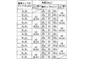
- It is a schematic front view of the circular saw which shows the modification 1 of the Example shown in FIG. 3 is a table showing pitches of a circular saw chip group A and a chip group B shown in a modification example 1 of FIG. 2 and pitches of adjacent chips.
- FIG. 5 It is a schematic front view of the circular saw which shows the modification 2 of the Example shown in FIG. 5 is a table showing pitches of a circular saw chip group A and a chip group B and a pitch of adjacent chips shown in Modification 2 of FIG. 4.
- FIG. 7 It is a schematic front view of the circular saw which shows the modification 3 of the Example shown in FIG. 7 is a table showing pitches of a circular saw chip group A, a chip group B, and a chip group C shown in Modification Example 3 of FIG. 6 and pitches of adjacent chips.
- the circular saw according to the present invention has the above-described basic structure in which the pitch of a plurality of cutting tips bonded to the outer periphery of the circular saw base is intentionally changed in order to reduce noise when cutting a work material. It is common with the conventional circular saw. However, in the present invention, a certain regularity is given to the pitch of the cutting tip so that the cutting tip can be polished within the range of numerical control by the automatic polishing machine.
- FIG. 1 shows an arrangement of cutting tips in a circular saw according to a preferred embodiment of the present invention.
- FIG. 1 (b) shows a circular saw 10 in which a number of cutting tips 14 are joined to an outer periphery of a base metal 12.
- 1 (a) is a partial plan view of the arrangement of the cutting tips 14 shown in FIG. 1 (b) observed from above.
- the number of cutting chips in the chip group A is 75
- the number of cutting chips in the chip group B is 75. That is, as shown in FIGS. 1A and 1B, on the outer periphery of the base metal 12, the chips A 1 to A 75 of the chip group A in which a plurality of cutting tips 14 are arranged on the outer periphery of the circular saw 10 as well.
- the chips B 1 to B 75 of the chip group B are alternately arranged.
- the number of cutting chips 14 in each of the chip groups A (B) may be arbitrary. Further, in this embodiment, two groups of the chip groups A and B are used, but the number of chip groups may be further increased.
- the chip A 0 is used to indicate an arbitrary chip in the chip group A.
- the chip A 1 , chip A 2, ... Chip A m ⁇ 1 it referred to as the chip a m.
- the chip B 0 is used when indicating an arbitrary chip in the chip group B, and when indicating an individual specific chip, the chip B 1 , chip B 2, ... Chip B n ⁇ 1 , chip Bn .
- the pitch of the chip A 0 constituting the chip group A has become equal pitch chi.
- the pitch between the last chip A 75 and the first chip A 1 in the base metal circumferential direction is set to a pitch ⁇ ′ different from the equal pitch ⁇ .
- All pitch of the chip B 0 in the chip group B has become equal pitch y.
- the chips A 0 , B 0 ,... Of the same chip group A, B,. More than one are not continuously arranged in the outer peripheral direction.
- ⁇ 4.8196 °
- ⁇ ′ 3.3496 °
- y 4.8 °.
- each of the chips A 0 and B 0 in the chip group A and the chip group B as shown in FIG. 1C, for example, three types of chips having different shapes are represented by (1), (2), (3), The arrangement is repeated in the order of (1), (2), (3),. That is, in FIG. 1C, the tip cutting edge of the tip shown in (1) is inclined on the right side, and the tip cutting edge of the tip shown in (2) is inclined on the left side. The tip cutting edge of the tip shown in (3) is inclined on both sides. Thus, the noise at the time of cutting can be suppressed low by sequentially changing the shape of the rake face of each chip.
- the cutting noise when cutting an aluminum sash at a rotation speed of 3600 rpm using a circular saw having an outer diameter of 455 mm is 98 dBA, which is lower than that of a conventional circular saw having all teeth having the same pitch of 103 dBA.
- the chip (1) and the chip (2) may be provided with a horizontal rake angle, in which case the noise can be further reduced.
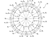
- the first modification relates to another pitch in the cutting tip 14.
- the circular saw 10 shown in FIG. 2 includes the tip A 0 of the tip group A including the large number of cutting tips 14 and the tip group B similarly. and chip B 0 are alternately arranged.
- the pitch of each chip shown in FIG. 2 is represented by a central angle.
- each central angle in the chip groups A and B has a relationship shown in the table of FIG.
- the pitch of the chip A 1 and the chip A 2 is 60 ° to the sum of the pitch alpha 1 of the adjacent chip (25 °) and of the adjacent chip pitch ⁇ 2 (35 °), chip A 2 and the chip pitch of a 3 in the 60 ° of the sum of the pitch alpha 3 of the adjacent chip (27 °) to the pitch ⁇ 4 (33 °) of the adjacent chip, following the same way and the last chip a 6 and the first chip a 1 the pitch is adapted to 60 ° of the sum of the pitch alpha 11 adjacent the chip and the pitch alpha 12 adjacent chips. Therefore, in the embodiment shown in FIG. 2, the pitches in the chip group A are all equal.
- the pitch between the chip B 1 and the chip B 2 is 62 ° which is the sum of the pitch ⁇ 2 (35 °) of the adjacent chip and the pitch ⁇ 3 (27 °) of the adjacent chip, and the chip B 2 and the chip B
- the pitch of 3 is 62 ° which is the sum of the pitch ⁇ 4 (33 °) of the adjacent chip and the pitch ⁇ 5 (29 °) of the adjacent chip.
- the pitch of chip B 5 and chip B 6 is adjacent.
- the sum of the pitch ⁇ 10 (27 °) of the chip and the pitch ⁇ 11 (35 °) of the adjacent chip is 62 °.
- the pitch between the last chip B 6 and the first chip B 1 is 50 ° which is the sum of the pitch ⁇ 12 (25 °) of the adjacent chip and the pitch ⁇ 1 (25 °) of the adjacent chip, and is earlier than that. Is different from the pitch 62 ° of each chip in the chip group B.
- the adjacent chips of the circular saw are six types in the range of 25 ° to 35 °, and are arranged irregularly and at an irregular pitch.
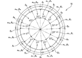
- Modification 2 Next, in Modification Example 2 shown in FIGS. 4 and 5, in one chip group A, there is one in which the pitch between the chip A 0 and the next chip A 0 is not equal, and also in the other chip group B, shows an embodiment in which unequal to the pitch of the chip B 0 and the next chip B 0 is present.
- a chip A 0 of chip group A consisting of the plurality of cutting tip 14, also is the chip B 0 of chip group B are alternately arranged.
- the pitch of each chip shown in FIG. 4 is represented by a central angle.
- each central angle in the chip groups A and B has the relationship shown in the table of FIG.
- the pitch between the chips A 1 and A 2 is 58 ° which is the sum of the pitch ⁇ 1 (25 °) of the adjacent chip and the pitch ⁇ 2 (33 °) of the adjacent chip
- the sum of the pitch ⁇ 9 (41 °) and the pitch ⁇ 10 (17 °) of the adjacent chip is 58 °.
- the pitch of the chip A 6 and the chip A 1 is adapted to 70 ° of the sum of the pitch of the adjacent chip ⁇ 11 (45 °) to the pitch ⁇ 12 (25 °) of the adjacent chip.
- the chip group B, the pitch of the chip B 1 and the chip B 2 is, 62 ° of the sum of the pitch beta 2 adjacent chip (33 °) to the pitch ⁇ 3 (29 °) of the adjacent chip, chip B 2 and the chip pitch of B 3, the pitch of the adjacent chip pitch beta 4 and (29 °) at 62 ° of the sum of the pitch ⁇ 5 (33 °) of the adjacent chip, and the chip B 5 and the chip B 6 in the same manner the The sum of the pitch ⁇ 10 (17 °) of the adjacent chip and the pitch ⁇ 11 (45 °) of the adjacent chip is 62 °.
- the pitch between the last chip B 6 and the first chip B 1 is 50 ° which is the sum of the pitch ⁇ 12 (25 °) of the adjacent chip and the pitch ⁇ 1 (25 °) of the adjacent chip. This is different from the previous pitch of 62 °.
- the pitches of the adjacent chips of the circular saw are unequally arranged at irregular intervals in eight types ranging from 17 ° to 45 °.
- the pitch of the chip A 0 in the chip group A are all equal.
- the chip group B, the pitch of the chip B 1 and the chip B 2 includes a pitch beta 2 adjacent chip (33 °), the pitch beta 3 adjacent chip (25 °), the pitch of the adjacent chip beta 4 ( 38.5 °), which is 88.5 °.
- the pitch of the chip B 2 and the chip B 3 includes a pitch beta 5 adjacent chips (31.5 °), the pitch beta 6 adjacent chip (28 °), the pitch beta 7 adjacent chip (29 °) 88.5 ° of the sum.
- the pitch of the chip B 3 and the chip B 4 includes a pitch beta 8 adjacent chip (30 °), the pitch beta 9 adjacent chips with (31 °), the pitch of the adjacent chip beta 10 (27.5 88.5 °).
- the pitch of the chip B 4 and the chip B 1 represents a pitch beta 11 of adjacent chips (28.5 °), and the pitch between adjacent chips ⁇ 12 (34 °), the pitch beta 1 adjacent chip (32 °) It is 94.5 ° of the sum.
- the chip group C, the pitch of chips C 1 and the chip C 2 includes a pitch gamma 3 of the adjacent chip (25 °), the pitch gamma 4 adjacent chips (30.5 °), the pitch between adjacent chips gamma 5 ( 31.5 °), which is 87 °.
- the pitch of the chip C 2 and the chip C 3 has a pitch gamma 6 adjacent chip (28 °), the pitch gamma 7 of adjacent chips (29 °), the sum of the pitch gamma 8 adjacent chip (30 °) 87 °.
- the pitches of the chips C 3 and C 4 are the pitch ⁇ 9 (31 °) of the adjacent chip, the pitch ⁇ 10 (27.5 °) of the adjacent chip, and the pitch ⁇ 11 (28 .5 °), which is 87 °.
- the pitch between the chips C 4 and C 1 is the sum of the pitch ⁇ 12 (34 °) of the adjacent chip, the pitch ⁇ 1 (32 °) of the adjacent chip, and the pitch ⁇ 2 (33 °) of the adjacent chip. It is 99 °.
- the pitches of the adjacent chips of the circular saw are unequal pitches in which all pitches are irregularly arranged in 12 types in a range of 25 ° to 34 °.
- the pitch of a large number of cutting tips is changed according to each chip group. Therefore, by simply storing the pitch of each chip group in the control device of the automatic polishing machine, the automatic polishing of each cutting chip can be achieved without a large numerical change.
- the chip group A polished by 60 ° pitch, then for chip group B can be polished at a 62 ° pitch after polishing chip B 1.
- polishing can be performed at a pitch of 58 ° from the chip A 1 of the chip group A and at a pitch of 62 ° from the chip B 1 of the chip group B.
Landscapes
- Engineering & Computer Science (AREA)
- Mechanical Engineering (AREA)
- Life Sciences & Earth Sciences (AREA)
- Wood Science & Technology (AREA)
- Forests & Forestry (AREA)
- Sawing (AREA)
- Polishing Bodies And Polishing Tools (AREA)
Abstract
Selon l'invention, en ce qui concerne de multiples pointes de coupe liées sur la périphérie d'un métal de base de scie circulaire, il est possible de réduire le bruit lors de la coupe d'une pièce à travailler en faisant varier le pas entre des pointes adjacentes. Cependant, un problème existait selon lequel, en fonction du pas des pointes de coupe, lesdites pointes ne pouvaient pas être polies au moyen d'une machine de polissage automatisée. La solution selon l'invention porte sur une scie circulaire (10) obtenue par liaison du nombre requis de pointes de coupe (14) sur la périphérie d'un métal de base (12), ladite scie circulaire étant conçue de telle sorte qu'un grand nombre de pointes de coupe (14) sont disposées en tant qu'au moins deux groupes de pointes (A, B, …) agencés en réseau sur la périphérie de la scie circulaire (10) ; le pas de chaque groupe de pointes (A, B, …) est réglé de façon à être le même, à l'exception du pas entre la dernière pointe (Am, Bn, …) et la première pointe (A1, B1, …) ; et le pas d'au moins l'un desdits groupes de pointes (A, B, …) est amené à différer du pas desdits autres groupes de pointes (A, B, …).
Priority Applications (2)
| Application Number | Priority Date | Filing Date | Title |
|---|---|---|---|
| CN201980032261.2A CN112088063B (zh) | 2018-08-08 | 2019-07-03 | 圆锯 |
| JP2020536384A JP7260547B2 (ja) | 2018-08-08 | 2019-07-03 | 丸鋸 |
Applications Claiming Priority (2)
| Application Number | Priority Date | Filing Date | Title |
|---|---|---|---|
| JP2018149711 | 2018-08-08 | ||
| JP2018-149711 | 2018-08-08 |
Publications (1)
| Publication Number | Publication Date |
|---|---|
| WO2020031565A1 true WO2020031565A1 (fr) | 2020-02-13 |
Family
ID=69413734
Family Applications (1)
| Application Number | Title | Priority Date | Filing Date |
|---|---|---|---|
| PCT/JP2019/026476 Ceased WO2020031565A1 (fr) | 2018-08-08 | 2019-07-03 | Scie circulaire |
Country Status (3)
| Country | Link |
|---|---|
| JP (1) | JP7260547B2 (fr) |
| CN (1) | CN112088063B (fr) |
| WO (1) | WO2020031565A1 (fr) |
Citations (5)
| Publication number | Priority date | Publication date | Assignee | Title |
|---|---|---|---|---|
| US5038653A (en) * | 1988-02-02 | 1991-08-13 | The Disston Company | Circular saw blade |
| JP2004050367A (ja) * | 2002-07-23 | 2004-02-19 | Tenryu Saw Mfg Co Ltd | ディスクカッター |
| JP2006142462A (ja) * | 2004-11-24 | 2006-06-08 | Kanefusa Corp | 回転切削工具 |
| EP3075480A1 (fr) * | 2015-04-02 | 2016-10-05 | Leitz GmbH & Co. KG | Lame de scie circulaire comprenant une denture de groupes |
| WO2016178307A1 (fr) * | 2015-05-07 | 2016-11-10 | 兼房株式会社 | Scie circulaire |
Family Cites Families (9)
| Publication number | Priority date | Publication date | Assignee | Title |
|---|---|---|---|---|
| DE4405475A1 (de) * | 1993-02-22 | 1994-08-25 | Miller Martin Ag | Kreissägeblatt |
| JP2000025006A (ja) * | 1998-07-15 | 2000-01-25 | Kanefusa Corp | 丸 鋸 |
| US7225715B2 (en) | 2002-03-19 | 2007-06-05 | Black & Decker Inc. | Variable tooth saw blade |
| JP4301806B2 (ja) * | 2002-12-19 | 2009-07-22 | 株式会社アマダ | 鋸刃 |
| US7913601B2 (en) * | 2006-04-28 | 2011-03-29 | Simonds International Corporation | Enhanced performance saw blade toothform pattern |
| CN101020345A (zh) * | 2006-09-26 | 2007-08-22 | 广西大学 | 多孔基体与非等弧长节块复合结构的减振降噪金刚石圆锯片 |
| CN102179566B (zh) * | 2011-04-01 | 2012-12-26 | 山东黑旋风锯业有限公司 | 复合型消音硬质合金锯片及其制造方法 |
| JP5903345B2 (ja) * | 2012-07-17 | 2016-04-13 | 株式会社アマダホールディングス | 鋸刃各歯の最適配置方法及び鋸刃 |
| JP5827281B2 (ja) * | 2013-08-23 | 2015-12-02 | サンゴバン株式会社 | 切断ブレード |
-
2019
- 2019-07-03 JP JP2020536384A patent/JP7260547B2/ja active Active
- 2019-07-03 CN CN201980032261.2A patent/CN112088063B/zh not_active Expired - Fee Related
- 2019-07-03 WO PCT/JP2019/026476 patent/WO2020031565A1/fr not_active Ceased
Patent Citations (5)
| Publication number | Priority date | Publication date | Assignee | Title |
|---|---|---|---|---|
| US5038653A (en) * | 1988-02-02 | 1991-08-13 | The Disston Company | Circular saw blade |
| JP2004050367A (ja) * | 2002-07-23 | 2004-02-19 | Tenryu Saw Mfg Co Ltd | ディスクカッター |
| JP2006142462A (ja) * | 2004-11-24 | 2006-06-08 | Kanefusa Corp | 回転切削工具 |
| EP3075480A1 (fr) * | 2015-04-02 | 2016-10-05 | Leitz GmbH & Co. KG | Lame de scie circulaire comprenant une denture de groupes |
| WO2016178307A1 (fr) * | 2015-05-07 | 2016-11-10 | 兼房株式会社 | Scie circulaire |
Also Published As
| Publication number | Publication date |
|---|---|
| CN112088063B (zh) | 2023-03-28 |
| CN112088063A (zh) | 2020-12-15 |
| JPWO2020031565A1 (ja) | 2021-08-12 |
| JP7260547B2 (ja) | 2023-04-18 |
Similar Documents
| Publication | Publication Date | Title |
|---|---|---|
| JP4447665B2 (ja) | 改良された帯鋸 | |
| US7640838B2 (en) | Saw blade with secondary teeth separated by deep gullets | |
| AU617313B2 (en) | Circular saw blade | |
| US20070193427A1 (en) | Bandsaw blade and cutter tooth arrangement therfor | |
| US10328503B2 (en) | T-slot cutter | |
| TW269653B (en) | Saw blade tooth form and method therefor | |
| US2528226A (en) | Circular saw and method of making same | |
| BR0101513A (pt) | Corpo cortante para uma ferramenta de corterotativa, e, ferramenta de corte com duas placasde corte | |
| JPS58132417A (ja) | 歯面を切削加工する工具 | |
| US8042443B2 (en) | Disk-shaped tool with vibration reduction | |
| US4034638A (en) | Circular saw having reduced noise | |
| US156748A (en) | Improvement in circular saws | |
| WO2020031565A1 (fr) | Scie circulaire | |
| CN210525162U (zh) | 切割锯 | |
| US5529528A (en) | Saw blade with sanding surface | |
| US20060207402A1 (en) | Saw blade | |
| JPH08187702A (ja) | 低騒音丸鋸 | |
| RU2004101704A (ru) | Круглая строгальная пила | |
| JP2509299Y2 (ja) | 回転切削工具 | |
| JP2020519465A (ja) | 多刃リーマ | |
| US11376679B2 (en) | Bandsaw blade | |
| US3814155A (en) | Tool heads for use in machining timber | |
| CN110449668B (zh) | 一种高效齿轮铣刀 | |
| CN202344068U (zh) | 一种螺纹加工刀片 | |
| JPH07323403A (ja) | 超硬丸のこ |
Legal Events
| Date | Code | Title | Description |
|---|---|---|---|
| 121 | Ep: the epo has been informed by wipo that ep was designated in this application |
Ref document number: 19846070 Country of ref document: EP Kind code of ref document: A1 |
|
| ENP | Entry into the national phase |
Ref document number: 2020536384 Country of ref document: JP Kind code of ref document: A |
|
| NENP | Non-entry into the national phase |
Ref country code: DE |
|
| 122 | Ep: pct application non-entry in european phase |
Ref document number: 19846070 Country of ref document: EP Kind code of ref document: A1 |