WO2020031579A1 - Procédé de production d'un alliage super résistant à la chaleur à base de ni, et alliage super résistant à la chaleur à base de ni - Google Patents
Procédé de production d'un alliage super résistant à la chaleur à base de ni, et alliage super résistant à la chaleur à base de ni Download PDFInfo
- Publication number
- WO2020031579A1 WO2020031579A1 PCT/JP2019/026836 JP2019026836W WO2020031579A1 WO 2020031579 A1 WO2020031579 A1 WO 2020031579A1 JP 2019026836 W JP2019026836 W JP 2019026836W WO 2020031579 A1 WO2020031579 A1 WO 2020031579A1
- Authority
- WO
- WIPO (PCT)
- Prior art keywords
- heat
- plastic working
- less
- heat treatment
- working
- Prior art date
- Legal status (The legal status is an assumption and is not a legal conclusion. Google has not performed a legal analysis and makes no representation as to the accuracy of the status listed.)
- Ceased
Links
Images







Classifications
-
- C—CHEMISTRY; METALLURGY
- C22—METALLURGY; FERROUS OR NON-FERROUS ALLOYS; TREATMENT OF ALLOYS OR NON-FERROUS METALS
- C22C—ALLOYS
- C22C19/00—Alloys based on nickel or cobalt
- C22C19/03—Alloys based on nickel or cobalt based on nickel
- C22C19/05—Alloys based on nickel or cobalt based on nickel with chromium
-
- C—CHEMISTRY; METALLURGY
- C22—METALLURGY; FERROUS OR NON-FERROUS ALLOYS; TREATMENT OF ALLOYS OR NON-FERROUS METALS
- C22F—CHANGING THE PHYSICAL STRUCTURE OF NON-FERROUS METALS AND NON-FERROUS ALLOYS
- C22F1/00—Changing the physical structure of non-ferrous metals or alloys by heat treatment or by hot or cold working
- C22F1/10—Changing the physical structure of non-ferrous metals or alloys by heat treatment or by hot or cold working of nickel or cobalt or alloys based thereon
-
- C—CHEMISTRY; METALLURGY
- C22—METALLURGY; FERROUS OR NON-FERROUS ALLOYS; TREATMENT OF ALLOYS OR NON-FERROUS METALS
- C22F—CHANGING THE PHYSICAL STRUCTURE OF NON-FERROUS METALS AND NON-FERROUS ALLOYS
- C22F1/00—Changing the physical structure of non-ferrous metals or alloys by heat treatment or by hot or cold working
Definitions
- the present invention relates to a method for producing a Ni-base super-heat-resistant alloy and a Ni-base super-heat-resistant alloy. More specifically, the present invention relates to a Ni-base super-heat-resistant alloy having a gamma prime phase equilibrium precipitation at 700 ° C. of 35 mol% or more. The present invention relates to a method for producing a heat-resistant alloy and a Ni-based super heat-resistant alloy.
- Ni-based super heat-resistant alloys such as Inconel (registered trademark) 718 alloy are often used. With the high performance and low fuel consumption of gas turbines, heat-resistant parts having high heat-resistant temperatures are required.
- a gamma prime (hereinafter also referred to as “ ⁇ ′”) phase which is a precipitation strengthening phase of an intermetallic compound having Ni 3 Al as a main composition.
- the high-temperature strength of the Ni-based super heat-resistant alloy can be further improved by further containing Al, Ti, and Nb, which are ⁇ '-forming elements, in the Ni-based super heat-resistant alloy.
- a Ni-based super heat-resistant alloy having a larger amount of ⁇ 'phase is required.
- Ni-base super heat-resistant alloy is difficult to work because the deformation resistance of hot working increases as the ⁇ 'phase increases.
- the amount of the ⁇ 'phase is 35 to 40 mol% or more, the processability is particularly reduced.
- alloys such as Inconel (registered trademark) 713C alloy, IN939, IN100, and Mar-M247 have a specially large ⁇ 'phase, which makes plastic working impossible, and is usually as-cast as a cast alloy. Used in.
- Patent Document 1 discloses a Ni-based super heat-resistant alloy ingot having a composition in which the ⁇ ′ mole ratio is 40 mol% or more, and a work rate of 5%.
- a manufacturing method is described in which cold working is performed at less than 30% and then heat treatment is performed at a temperature exceeding the ⁇ ′ solid solution temperature. This method obtains a recrystallization rate of 90% or more at which hot working can be applied to a Ni-base super heat-resistant alloy by a combination of a cold working step and a heat treatment step.
- a thin wire of a Ni-base super heat-resistant alloy is required as a forming material.
- This thin wire can be used after being processed into a part shape such as a spring.
- the wire diameter (diameter) of the fine wire of the Ni-base super heat-resistant alloy is as thin as, for example, 5 mm or less, and further 3 mm or less.
- Patent Document 1 is effective for Ni-base super heat-resistant alloys to which hot working is applied.
- the method of Patent Document 2 is effective for producing a fine wire with a limited component composition, but can be applied only to the component composition, and the amount of the ⁇ ′ phase is “35 mol% or more” described later.
- the method of Patent Document 2 has a problem that the process is complicated and the manufacturing cost is increased. Further, in producing a fine wire or a wire rod, if a crack occurs in the middle of the process, the processing rate is limited, and there has been a problem that a plastic working cannot be performed to a predetermined wire diameter.
- a method of manufacturing a Ni-base superalloy comprising (A) a material having a carbon content of 0.01 to 0.25% by mass and a component composition in which the equilibrium precipitation amount of a gamma prime phase at 700 ° C. is 35 mol% or more is 500 ° C. or less; A step of performing a plurality of times of plastic working so that the cumulative working ratio from the material is 40% or more to produce a first working material; (B) performing a heat treatment on the first processed material at a temperature of 900 ° C.
- the first heat-treated material is subjected to one or more times of plastic working at a temperature of 500 ° C. or less so that the cumulative working ratio from the first heat-treated material is 10% or more. 2) a step of producing a processed material.
- the method further includes (d) a step of performing a heat treatment on the second workpiece at a temperature of 900 ° C. or higher.
- step (c) it is preferable to perform the set of the steps (b) and (c) one or more times to produce a second processed material.
- the working ratio of one plastic working in the plastic working of steps (a) and (c) is 30% or less.
- the step (b) includes a step of removing the surface of the material after the heat treatment.
- the Ni-based super heat-resistant alloy is C: 0.01 to 0.25%, Cr: 8.0 to 25.0%, Al: 0.5 to 8.0%, Ti: 0.4 to 7.0%, Co: 0 to 28.0%, Mo: 0 to 8.0%, W: 0 to 15.0%, Nb: 0 to 4.0%, Ta: 0 to 5.0%, Fe: 0 to 10.0%, V: 0 to 1.2%, Hf: 0 to 3.0%, B: 0 to 0.300%, Zr: 0 to 0.300% And the balance preferably has a composition consisting of Ni and impurities.
- a method of manufacturing a Ni-based superalloy (A) A material having a carbon content of 0.01 to 0.25% by mass and a component composition having an equilibrium precipitation amount of a gamma prime phase at 700 ° C. of 35 mol% or more at a temperature of 500 ° C. or less, A step of performing a plastic working to produce a first processed material; (B) heat-treating the first processed material at a temperature of 900 ° C. or higher to produce a first heat-treated material; (C) performing a plastic working on the first heat-treated material at a temperature of 500 ° C.
- step (A) Performing the set of step (A) and step (B) one or more times, Finally if the first dimension d perpendicular to the longitudinal direction of the workpiece to be subjected to a heat treatment step (B) is more than 1.5 times the final product dimensions d f for performing, or size d the difference d-d f of the final product dimensions d f is of 1mm greater.
- Ni-base superalloy has a component composition in which the carbon content is 0.01 to 0.25 mass% and the equilibrium precipitation amount of the gamma prime phase at 700 ° C. is 35 mol% or more.
- the defect rate is 0.5 area% or less.
- EBSD electron backscatter diffraction
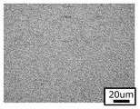
- 7 is a cross-sectional microstructure (curling liquid etching) of an outer peripheral portion of a wire having a wire diameter of 1.0 mm in Example 1.
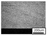
- 7 is a cross-sectional microstructure (curling liquid etching) of a central portion of a wire having a wire diameter of 1.0 mm in Example 1.
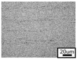
- 14 is a cross-sectional microstructure (curling liquid etching) of an outer peripheral portion of a wire having a wire diameter of 2.5 mm in Example 3.
- 14 shows a cross-sectional microstructure (curling liquid etching) of a central portion of a wire having a wire diameter of 2.5 mm in Example 3.
- 14 is an EBSD image showing an example of a cross-sectional structure of a hot extruded material (raw material) in Example 4.
- FIG. 8 is a diagram showing a grain size distribution of crystal grains recognized in the EBSD image of FIG. 7.
- 14 is a microstructure photograph showing an example of a cross-sectional structure of a hot extruded material (raw material) in Example 4.
- 11 is a microstructure photograph of a material (diameter: 4.5 mm) after the first plastic working in Example 4.
- 11 is a microstructure photograph of a material (diameter: 4.5 mm) after the first heat treatment in Example 4.
- 19 is a microstructure photograph of the material (diameter: 4.0 mm) after the fourth pass in the second plastic working in Example 4.
- the present invention provides a new method capable of producing a Ni-base super heat-resistant alloy having excellent plastic workability by a new approach different from conventional hot plastic working.
- the present inventors have studied the plastic workability of a Ni-base superalloy having a large amount of ⁇ 'phase. As a result, the inventors have found a phenomenon in which cold plastic working can be performed on a Ni-base super heat-resistant alloy material at a working ratio of 40% or more. At that time, it was found that nanocrystalline grains were generated in the structure of the Ni-base superalloy by cold plastic working at a working ratio of 30% or more. It is presumed that the formation of the nanocrystal grains contributes to a drastic improvement in the plastic workability of the Ni-base superalloy.
- the method for producing a Ni-base superalloy having a component composition in which the equilibrium precipitation amount of the gamma prime phase at 700 ° C. is not less than 35 mol% according to the present invention is as follows.
- the first heat-treated material is subjected to one or more times of plastic working at a temperature of 500 ° C. or less so that the cumulative working rate from the first heat-treated material becomes 10% or more. And a step of producing a second processed material.
- the Ni-base superalloy targeted by the present invention has a carbon content of 0.01 to 0.25% by mass and an equilibrium precipitation amount of gamma prime ( ⁇ ′) phase at 700 ° C. of 35 mol% or more. Having a composition.
- the amount of the ⁇ ′ phase of the Ni-based super heat-resistant alloy can be represented by a numerical index such as “volume ratio” or “area ratio” of the ⁇ ′ phase.
- the amount of the ⁇ ′ phase is expressed by a numerical index of “ ⁇ ′ molar ratio”.
- the ⁇ ′ molar ratio is a stable equilibrium precipitation amount of a gamma prime phase at which a Ni-base superalloy can precipitate in a thermodynamic equilibrium state.
- the value in which the equilibrium precipitation amount of the gamma prime phase is represented by “molar ratio” is determined by the component composition of the Ni-base superalloy.
- the value of mol% of the equilibrium precipitation amount can be determined by analysis by thermodynamic equilibrium calculation. In the analysis by thermodynamic equilibrium calculation, it is possible to accurately and easily obtain the accuracy by using various thermodynamic equilibrium calculation software.
- the ⁇ ′ molar ratio of the Ni-base superalloy is defined as “equilibrium precipitation at 700 ° C.”.
- the high-temperature strength of the Ni-base superalloy can be evaluated by the equilibrium precipitation amount of the gamma prime phase in the structure, and the higher the high-temperature strength, the more difficult the hot plastic working becomes.
- the equilibrium precipitation amount of the gamma prime phase in the structure generally has a small temperature dependence at about 700 ° C. or less and becomes substantially constant. Therefore, the value at the above “700 ° C.” is used as a reference.
- nano crystal grains are most easily generated from a phase interface between an austenite phase (gamma ( ⁇ )), which is a matrix of the Ni-base superalloy, and a gamma prime phase.
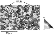
- FIG. 1 shows an example of an EBSD image of a cross-sectional microstructure generated by cold plastic working of a wire in the manufacturing method of the present invention.
- the measurement conditions of EBSD are as follows: Scanning electron microscope “ULTRA55 (manufactured by Zeiss)” EBSD measurement system “OIM Version 5.3.1 (manufactured by TSL Solution)” attached to the scanning electron microscope, magnification: 10000 times, scanning Step: The grain boundary was defined as 0.01 ⁇ m, and the crystal grain was defined as having a misorientation of 15 ° or more.
- the maximum diameter (maximum length) of the nanocrystal grains (encircled portion) confirmed in the EBSD image in FIG. 1 is as small as about 25 nm.
- a component composition in which the equilibrium precipitation amount of the gamma prime phase at 700 ° C. is 40 mol% or more is more preferable. More preferably, the equilibrium precipitation amount of the gamma prime phase is 50 mol% or more, and still more preferably 60 mol% or more.
- the particularly preferred equilibrium precipitation amount of the gamma prime phase is 63 mol% or more, more preferably 66 mol% or more, and even more preferably 68 mol% or more.
- the upper limit of the equilibrium precipitation amount of the gamma prime phase at 700 ° C. is not particularly limited, but is practically about 75 mol%.
- Ni-base superalloy having an equilibrium precipitation amount of the gamma prime phase at 700 ° C. of 35 mol% or more, for example, in mass%, C: 0.01 to 0.25%, Cr: 8.0 to 25.0%, Al: 0.5 to 8.0%, Ti: 0.4 to 7.0%, Co: 0 to 28.0%, Mo: 0 to 8.0%, W: 0 to 15 0.0%, Nb: 0 to 4.0%, Ta: 0 to 5.0%, Fe: 0 to 10.0%, V: 0 to 1.2%, Hf: 0 to 3.0%, B : 0 to 0.300% and Zr: 0 to 0.300%, with the balance being preferably composed of Ni and impurities.
- C is contained as an element for improving the castability of a Ni-base superalloy.
- Ni-base super heat-resistant alloys having a large amount of ⁇ 'phase are usually used as cast parts because plastic working is difficult, and a certain amount of C is added. This added C remains in the cast structure as carbides, and some are formed as coarse eutectic carbides. Such a coarse carbide becomes a starting point of a crack and a propagation path of the crack when the Ni-base superalloy is plastically worked, particularly when it is plastically worked at room temperature. Adversely affect sex.
- the Ni-base superalloy having a large amount of the ⁇ 'phase is not used as a cast part, but for the present invention aimed at producing the Ni-base superalloy by plastic working, the Ni-base superalloy in the Ni-base superalloy It is preferable to reduce C.
- the content of C is set to 0.25% or less. Preferably it is 0.20% or less. It is more preferably at most 0.15%.
- C is also an element that increases the strength of the heat-resistant component, and it is preferable that C be contained in consideration of producing or repairing such a heat-resistant component.
- the method for producing a Ni-based super heat-resistant alloy of the present invention plastic working becomes possible even with an alloy having a high C content due to the effect of the nanocrystal grains described above. Even in such a case, in the case of an alloy having a high C content, if a fine wire or a wire is to be produced by plastic working, the working ratio is limited by the problem that the above-mentioned carbide can be a starting point of a crack and a crack propagation path.
- the first and second intermediate heat treatments described below can cope with the above-described problem of carbide cracking. For example, the same C content as that in a cast part can be allowed. .
- C is contained at 0.01% or more. It is preferably at least 0.03%, more preferably at least 0.05%, further preferably at least 0.07%. Furthermore, C may be contained at 0.1% or more.
- Chrome (Cr) Cr is an element that improves oxidation resistance and corrosion resistance. However, when Cr is excessively contained, an embrittlement phase such as a sigma (sigma) phase is formed, and strength and hot workability at the time of material preparation are reduced. Therefore, the content of Cr is preferably set to, for example, 8.0 to 25.0%. More preferably, it is 8.0 to 22.0%. A preferred lower limit is 9.0%, and a more preferred lower limit is 9.5%. A more preferred lower limit is 10.0%. Further, a preferred upper limit is 18.0%, and a more preferred upper limit is 16.0%. A more preferred upper limit is 14.0%. A particularly preferred upper limit is 12.5%.
- Mo Molybdenum
- Mo contributes to solid solution strengthening of the matrix and has an effect of improving high-temperature strength.
- Mo is set to 0 to 8.0% (it may be not added (or may be an unavoidable impurity level)). More preferably, it is 2.0 to 7.0%.
- a still more preferred lower limit is 2.5%, and a more preferred lower limit is 3.0%.
- a more preferred lower limit is 3.5%.
- a more preferable upper limit is 6.0%, and a more preferable upper limit is 5.0%.
- Aluminum (Al) Al is an element that forms a ⁇ ′ (Ni 3 Al) phase as a strengthening phase and improves high-temperature strength.
- the content of Al is preferably 0.5 to 8.0%. More preferably, it is 2.0 to 8.0%.
- a still more preferred lower limit is 2.5%, and a more preferred lower limit is 3.0%.
- a still more preferred lower limit is 4.0%, and a still more preferred lower limit is 4.5%.
- a particularly preferred lower limit is 5.1%.
- a more preferred upper limit is 7.5%, and a more preferred upper limit is 7.0%.
- a more preferred upper limit is 6.5%.
- the reduced Al content can be allowed.
- the upper limit of Cr is set to 13.5%
- the lower limit of the Al content is preferably set to 3.5%.
- Titanium (Ti) Ti is an element that forms a ⁇ ′ phase and solid-solution strengthens the ⁇ ′ phase to increase the high-temperature strength.
- Ti is preferably, for example, 0.4 to 7.0%.
- a preferable lower limit of Ti is 0.6%, and a more preferable lower limit is 0.7%.
- a more preferred lower limit is 0.8%.
- a preferable upper limit is 6.5%, and a more preferable upper limit is 6.0%.
- a more preferred upper limit is 4.0%, and a particularly preferred upper limit is 2.0%.
- Co Cobalt (Co) Co improves the stability of the structure, and makes it possible to maintain the hot workability at the time of preparing the material, even if a large amount of Ti as a strengthening element is contained.
- Co is one of the optional elements that can be contained in a range of, for example, 28.0% or less in combination with another element.
- a preferable lower limit when Co is added is set to 8.0%.
- a more preferred lower limit is 10.0%.
- a preferable upper limit of Co is 18.0%.
- a more preferred upper limit is 16.0%. If Co may be added at a non-addition level (the unavoidable impurity level of the raw material) based on the balance with the ⁇ ′ generating element and the Ni matrix, the lower limit of Co is set to 0%.
- Tungsten (W) W is one of the selective elements that contribute to the solid solution strengthening of the matrix.
- the upper limit is set to 15.0%.
- a preferred upper limit is 13.0%, a more preferred upper limit is 11.0%, and a still more preferred upper limit is 9.0%.
- the lower limit of W is preferably set to 1.0%.
- the lower limit of W may be 3.0%, 5.0%, or 7.0%.
- W is preferably added at 0.8% or more. Note that, in the case where W can be set to the non-addition level (the unavoidable impurity level of the raw material) by sufficient addition of Mo, the lower limit of W is set to 0%.
- Nb Niobium (Nb) Like Al and Ti, Nb is one of the selected elements that forms a ⁇ ′ phase and strengthens the ⁇ ′ phase by solid solution strengthening to increase the high-temperature strength. However, excessive addition of Nb forms a harmful ⁇ (delta) phase, and impairs hot workability in preparing a material. Therefore, the upper limit of Nb is, for example, 4.0%. A preferred upper limit is 3.5%, and a more preferred upper limit is 2.5%. In order to more reliably exert the effect of Nb, the lower limit of Nb is preferably set to 1.0%. A preferable lower limit is set to 2.0%. In a case where Nb may be at a non-addition level (inevitable impurity level) by adding another ⁇ ′ generating element, the lower limit of Nb is set to 0%.
- Tantalum (Ta) Ta is one of the selected elements that forms a ⁇ ′ phase and solid-solution strengthens the ⁇ ′ phase to increase the high-temperature strength.
- Ta is set to, for example, 5.0% or less. It is preferably at most 4.0%, more preferably at most 3.0%, even more preferably at most 2.5%.
- the lower limit of Ta is preferably set to 0.3%.
- the lower limit of Ta may be set to 0.8%, 1.5%, and 2.0%.
- the lower limit of Ta is set to 0%.
- Iron (Fe) Fe is one of the selective elements used as a substitute for expensive Ni and Co, and is effective in reducing alloy costs. In order to obtain this effect, it is better to determine whether to add in combination with other elements. However, when Fe is contained excessively, an embrittlement phase such as a sigma (sigma) phase is formed, and the strength and the hot workability in preparing the material are reduced. Therefore, the upper limit of Fe is, for example, 10.0%. A preferred upper limit is 9.0%, and a more preferred upper limit is 8.0%. On the other hand, in the case where Fe may be added at a non-addition level (inevitable impurity level) based on the balance with the ⁇ ′ generating element and the Ni matrix, the lower limit of Fe is set to 0%.
- Vanadium (V) V is one of the selective elements useful for solid solution strengthening of the matrix and grain boundary strengthening by carbide formation.
- the upper limit of V is, for example, 1.2%.
- a preferred upper limit is 1.0%, and a more preferred upper limit is 0.8%.
- the lower limit of V is preferably set to 0.5% in order to more reliably exert the effect of V described above.
- V may be a non-addition level (inevitable impurity level) depending on the balance with other alloy elements in the alloy
- the lower limit of V is set to 0%.
- Hafnium (Hf) Hf is one of the selective elements useful for improving the oxidation resistance of the alloy and strengthening the grain boundary by forming carbides.
- the upper limit of Hf is, for example, 3.0%, preferably 2.0%, and more preferably 1.5%.
- the lower limit of Hf is preferably set to 0.1% in order to more reliably exert the effect of Hf.
- the lower limit of Hf can be set to 0.5%, 0.7%, and 1.0%.
- the lower limit of Hf is set to 0%.
- B B is an element that improves grain boundary strength and improves creep strength and ductility.
- B does not exceed 0.300%, for example, because B has a large effect of lowering the melting point, and the formation of coarse borides impairs the hot workability during material preparation.
- a preferred upper limit is 0.200%, and a more preferred upper limit is 0.100%.
- a more preferred upper limit is 0.050%, and a particularly preferred upper limit is 0.020%.
- the content is preferably at least 0.001%.
- a more preferred lower limit is 0.003%, and a still more preferred lower limit is 0.005%.
- a particularly preferred lower limit is 0.010%.
- the lower limit of B is set to 0%.
- Zirconium (Zr) Zr like B, has the effect of improving the grain boundary strength.
- the upper limit of Zr is, for example, 0.300%.
- a preferred upper limit is 0.250%, and a more preferred upper limit is 0.200%.
- a more preferred upper limit is 0.100%, and a particularly preferred upper limit is 0.050%.
- the content is preferably 0.001% or more.
- a more preferred lower limit is 0.005%, and a still more preferred lower limit is 0.010%.
- the lower limit of Zr is set to 0%.
- Ni but may include unavoidable impurities.
- a material having the component composition described above is prepared.
- the method for producing this material is not particularly limited.
- this material can be obtained by a melting method in which a molten metal is poured into a mold to produce an ingot.
- vacuum melting and ordinary methods such as vacuum arc remelting and electroslag remelting may be combined and applied.
- the material may be obtained by a powder metallurgy method. Then, for the ingot or the alloy ingot produced by the powder metallurgy method, if necessary, hot working such as hot forging, hot rolling, hot extrusion or machining (for example, dimensional adjustment) Or cutting, polishing, grinding, etc.
- a material having a predetermined shape for example, a bar material shape.
- a heat treatment such as soaking can be performed between these operations. For example, soaking (for example, holding at 1100 ° C. to 1280 ° C. for 5 to 60 hours) may be performed to eliminate elemental segregation of the ingot. Alternatively, for example, soaking may be performed after finishing into a shape of a material (billet) to be subjected to hot extrusion.
- the structure of the material and the crystal grain size are not limited. Therefore, when the material is subjected to soaking or heat treatment, the subsequent cooling may be any of rapid cooling, cooling, and furnace cooling.
- the above-mentioned material is hot-extruded and finished into a bar-shaped material having a predetermined shape.
- the hot extrusion is preferably performed at an extrusion temperature (heating temperature of the material) of 1050 ° C. to 1200 ° C., an extrusion ratio of 4 to 20, and an extrusion speed (stem speed) of 5 to 80 mm / s.
- the cross-sectional diameter of extruded (material) is, for example, 10 mm or more, or more than 20 mm. And it is 200 mm or less, for example.
- the surface of the extruded material can be finished by machining or the like, or a bar having a predetermined size can be obtained from the extruded material.
- the cross-sectional diameter of the bar may be, for example, 150 mm or less, 100 mm or less, 50 mm or less, 30 mm or less, 10 mm or less. Further, the cross-sectional diameter of the bar may be, for example, 3 mm or more, 4 mm or more, 5 mm or more. Reducing the cross-sectional diameter of the bar is advantageous in that the number of plastic workings (the number of passes) can be reduced when a wire or a thin wire having a smaller cross-sectional diameter is produced by cold plastic working described later. preferable.
- the crystal grain size of the material is not limited. However, by performing hot extrusion, the material can have a recrystallized grain size of, for example, 200 ⁇ m or less.
- the recrystallized structure preferably has a size of 150 ⁇ m or less, more preferably 100 ⁇ m or less, and still more preferably 50 ⁇ m or less.
- the recrystallized structure preferably has a recrystallized structure of 0.1 ⁇ m or more, more preferably 0.5 ⁇ m or more, further preferably 0.8 ⁇ m or more, and still more preferably 1.5 ⁇ m or more.
- the crystal grains generated by recrystallization have less intragrain distortion, and the crystal grain boundaries are increased by making the crystal grains fine, so that if cold plastic working described later is performed on this, Processing strain is evenly applied to the entire tissue. Further, the refinement of the crystal grains is also effective in generating nanocrystal grains described later. Therefore, by performing this step, the deformation in the plastic processing in the next step becomes more uniform, and the occurrence of abnormal deformation or bending during the processing can be avoided, and the yield can be drastically improved. To further improve this effect, the hot extruded material may be subjected to a heat treatment for removing residual stress due to processing. The heat-treated material is cooled by standing to cool.
- the crystal grain size of the material can be confirmed by an EBSD image of the cross section of the material (FIG. 7).
- the measurement condition of EBSD is scan step: 0.1 ⁇ m, and the crystal grain size distribution showing the relationship between the maximum diameter and the number of the individual crystal grains with respect to the crystal grains recognizable at the grain boundary having the orientation difference of 15 ° or more. From FIG. 8, the average diameter of the maximum diameter of the crystal grains can be obtained.
- the crystal grain size distribution may be confirmed by those recognized as crystal grains under the above measurement conditions, and for example, can be confirmed by crystal grains having a maximum diameter of 0.2 ⁇ m or more.
- the crystal grain size of the material refers to the above-mentioned “average diameter of the maximum diameter of the crystal grains”.
- the carbide can also be recognized as a crystal grain defined by “a grain boundary having a misorientation of 15 ° or more” in the EBSD image (for example, an arrow in FIG. 7). In such a case, this carbide may also be included in the above-described crystal grain size distribution as crystal grains.
- the average diameter of the crystal grains of the Ni-base superalloy having a large amount of the ⁇ 'phase can be determined. It is suitable.
- the crystal grain size of the material can be measured from the cross-sectional structure of the material.
- the cross section of the material is corroded with a curling liquid, and the cross-sectional structure after the corrosion is observed with an optical microscope having a predetermined magnification.
- the evaluation can be performed using “grain size number G” based on JIS-G-0551 (ASTM-E112), and the result can be converted into “average diameter d of crystal grains” corresponding to the grain size number G.
- the crystal grain size of the material refers to the above-mentioned “average diameter d of crystal grains”.
- the crystal grain size of the material can also be evaluated by the method using the particle size number G.
- the hardness of the raw material is not limited, but is preferably low in order to secure the initial workability by cold plastic working in a state where the nanocrystal grains described later are not generated in the structure.
- it can be 550 HV or less or less than 500 HV. It is more preferably at most 470 HV, even more preferably at most 450 HV.
- the lower limit of the hardness of the material is not particularly limited, but about 250 HV is realistic. Then, for example, it can be set to 300 HV or more or 350 HV or more. Hardness greater than 400 HV can also be achieved.
- the hardness of the material can be measured on the cross section of the material.
- the above material is subjected to cold plastic working. More specifically, cold plastic working is performed a plurality of times so that the cumulative working ratio from the material becomes 40% or more.
- the present invention is different from the conventional "hot" plastic working in that a Ni-based superalloy is produced by "cold" plastic working.
- a cumulative working ratio of 40% or more can be obtained by cold plastic working, and processing is performed in hot plastic working.
- the plastic working temperature in the present invention is preferably set to “500 ° C. or less”.
- the temperature is more preferably 300 ° C. or lower, further preferably 100 ° C. or lower, even more preferably 50 ° C. or lower (for example, room temperature).
- the method for producing a Ni-based super heat-resistant alloy of the present invention is suitable for a wire material form, but can also be applied to a plate material, a band material and the like. Therefore, the Ni-base superalloy manufactured by the manufacturing method of the present invention has an intermediate product shape of a wire (wire @ material), a plate (sheet @ material), and a strip (strip @ material), and also has a fine wire (wire @ material). product, a thin product (sheet @ product), and a thin product (strip @ product). Regarding the relationship between the dimensions of a plate (thin plate) and a band (thin band), the wire diameter (diameter) of a wire (thin wire) can be read as a plate thickness or a band thickness.
- the hot-extruded material of the Ni-based super heat-resistant alloy is a bar
- bar processing for compressing the cross-sectional area can be performed.
- the "bar" of the Ni-base super heat-resistant alloy is used as a starting material, and as a mode of plastic working performed on this bar, pressure can be uniformly applied to the bar.
- Process of compressing the cross-sectional area of a simple cross-section ".
- the bar material is subjected to a process of plastically compressing the cross-sectional area (bar diameter) to increase the length.
- the processing rate is represented by the area reduction rate when swaging or die drawing is performed on the bar. Reduction of area, in relation to the cross-sectional area A 0 of the plastic working before the bar, the cross-sectional area A 1 of the wire and fine lines after the plastic working, [(A 0 -A 1 ) / A 0 ] ⁇ 100 (%) (1) Is calculated by the following equation. On the other hand, when rolling is performed, the processing rate is represented by the rolling reduction.
- the cumulative working rate indicates the working rate for the material of the final workpiece when plastic working is performed a plurality of times or over a plurality of passes.
- the cumulative working ratio from the above cold plastic working material is increased to 40% or more.
- the plastic working at this working rate can be completed not by one plastic working but by a plurality of plastic workings. No heat treatment is performed during multiple plastic workings.
- the heat treatment referred to here is a heat treatment in a high temperature region where recovery or recrystallization occurs, for example, heat treatment at a temperature exceeding 500 ° C.
- heat treatment is not required between passes of cold working, and a plurality of strong cold workings can be continuously performed to increase a cumulative working rate (cumulative surface reduction rate). It should be noted that formation of nanocrystal grains in the structure of the Ni-based super heat-resistant alloy that has been subjected to strong working can be observed.
- the cumulative working ratio is preferably set to 40% or more.
- the cumulative processing rate is preferably 45% or more, more preferably 50% or more, and even more preferably 55% or more.
- the upper limit of the cumulative processing rate is not particularly limited, but is preferably about 80%.
- the cumulative working rate it is preferable to temporarily set to 80% or less in order to make the effect of repairing material defects by the first heat treatment described later effective. It is more preferably at most 75%, further preferably at most 70%, even more preferably at most 65%. It is preferable that the processing rate (area reduction rate) by one plastic processing (pass) is 30% or less. More preferably, it can be 28% or less. This is because performing plastic working with a large working rate at one time may cause cracks or defects in the material.
- the working ratio of the one plastic working (pass) can be further reduced. For example, when the number of times of plastic working (pass) is three or more, the working rate by one plastic working (pass) can be set to a maximum of 25%. Further, when the number of times of the plastic working (pass) is four or more, the working rate by one plastic working (pass) can be set to a maximum of 23%.
- the working rate (reduction rate) in a given plastic working (pass) is calculated from the working rate (reduction rate) in the previous plastic working (pass). It is also possible to increase the processing efficiency by increasing the size.
- the processing rate may be increased for each plastic working (pass).
- the term “pass” refers to “1” when plastic working is performed by one (or a pair of) dies or rolls in the above-described plastic working such as swaging, die drawing, and rolling. Path ".
- one pass when used, it indicates the above-mentioned one “plastic working”.
- the material of the Ni-base super heat-resistant alloy is a bar
- plastic working such as compressing the cross-sectional area of the bar from the peripheral surface of the bar toward the axis is effective.
- a plastic working method in which pressure is evenly applied to the entire periphery of the bar to be plastically worked is advantageous. As a specific example, there is a swaging process.
- the swaging process is preferable for generating nanocrystal grains because the swaging process forges the circumferential surface of the bar while rotating a plurality of dies surrounding the entire circumference of the bar.
- other plastic working such as cassette roller die drawing and hole type die drawing can be applied.
- Step (b) [B] A heat treatment is performed on the processed material at a temperature of 900 ° C. or higher. The effect of this heat treatment will be described with reference to FIG.
- the Ni-based super heat-resistant alloy which has been subjected to the strong working with the cumulative working rate of 40% or more is in a state where the working can be further continued. Therefore, it is possible to perform cold working to a higher working ratio without performing heat treatment during plastic working.
- the Ni-base superalloy targeted by the present invention contains 0.01 to 0.25% by mass of carbon, coarse carbides 2 are precipitated in the structure of the raw material 1.
- the processed material 3 of the Ni-base superalloy after the cold plastic working (i) with the cumulative working ratio of 40% or more has a linear structure in which the ⁇ phase and the ⁇ 'phase extend in the stretching direction.
- the carbides are pulverized by plastic working to become fine carbides 4, but exist in the processed structure as carbide aggregates in which the fine carbides are connected in the direction in which the structure extends.
- Material defects 6 are formed between the fine carbides. If the plastic working (ii) is further performed in this state, the defects 6 between the fine carbides 4 may spread and combine with the adjacent defects 6, and may be a starting point of a crack.
- the material defect 6 formed between the fine carbides 4 is repaired by performing a heat treatment.
- the defect rate can be 0.5 area% or less. This is considered because the material softens and the alloy component fills the gap due to the diffusion of the alloy component. Therefore, when plastic working is further performed after the heat treatment (iii), cracks do not occur starting from material defects.
- the time of heat treatment that is, the stage at which the carbide aggregate connected in the stretching direction is formed differs depending on the carbide content, the size and type of the carbide depending on the material production method, and the like. For example, the cumulative processing rate is 40% or more.
- the target is 45% or more, 50% or more, 55% or more.
- the upper limit of the cumulative processing rate is preferably set to about 80%.
- the timing of the heat treatment varies depending on the carbide content, the size and type of the carbide depending on the material production method, and the like, but it is preferable to perform the heat treatment at a time when the wire diameter does not become too small. In the case where oxide scale or the like to be described later is removed after the heat treatment, if the wire diameter is too small, the rate of material loss due to this removal increases, and the product yield may be reduced. Then, for example, it is assumed that the wire diameter is 2.7 mm or more.
- the upper limit can be, for example, about 4.5 mm.
- the heat treatment is performed at 900 ° C. or higher. If the temperature is lower than 900 ° C., the above-mentioned defect is not repaired, that is, the alloy component is insufficient to diffuse the defect.
- the upper limit of the temperature of the heat treatment is not particularly limited, it is about 1200 ° C. Since the heat treatment aims at repairing the defect by processing as described above, it is sufficient if the defect can be repaired regardless of the solid solution of the ⁇ 'phase.
- the heat treatment time can be, for example, 10 minutes or more, 30 minutes or more, or 60 minutes or more depending on the size and shape of the material, and the upper limit may be appropriately determined, such as 120 minutes or less and 90 minutes or less.
- the heat treatment is preferably performed in an inert atmosphere such as a vacuum, a reducing atmosphere, or Ar to avoid surface oxidation, but may be performed in an oxidizing atmosphere (for example, an air atmosphere).
- an oxide scale is formed on the surface. If cold plastic working is performed while the oxide scale is formed, there is a possibility that cracks and defects may be formed. Then, you may remove mechanically or chemically by grinding
- the above heat treatment time is preferably completed in a short time, for example, 100 minutes or less, 90 minutes or less, or 80 minutes or less.
- the heat-treated material is further subjected to plastic working at a temperature of 500 ° C. or less. More specifically, plastic working is performed one or more times so that the cumulative working ratio from the heat-treated material is 10% or more.
- plastic working in the case of a wire, swaging, cassette roller die drawing, hole die drawing, and the like can also be used in the production of a sheet material, a band material, and the like. it can.
- the first heat treatment causes the reworked structure to recrystallize, but the material defects formed between the fine carbides are repaired, so that even if cold plastic working is further performed, cracks are generated from the material defects. There is no.
- plastic working is performed up to the final product dimensions.
- the hardness of the material of the final product dimensions can be 500 HV or more, 550 HV or more, 600 HV or more.
- the cumulative working ratio of the second plastic working can be 10% or more.
- the upper limit of the cumulative working rate is not particularly limited, a working rate similar to that of the first plastic working is aimed at.
- the cumulative working rate of the second plastic working is , Can be smaller than the cumulative working rate of the first plastic working.
- Other processing conditions are the same as in the first plastic working. For example, when performing plastic working a plurality of times, it is possible to increase the working rate in a given pass to be greater than the working rate in the previous pass to increase the working efficiency. The processing rate may be increased for each pass.
- Second heat treatment and third plastic working [re-process (b) [B] and process (c) [C]] If the second plastic working cannot be performed to the final product dimensions, the first heat treatment and the second plastic working described above can be further repeated one or more times to perform the processing to the target dimensions. Processing conditions, heat treatment conditions, and the like are as described above. For example, for the second heat treatment, the temperature, time, atmosphere, and the like can be determined in the manner of the first heat treatment. Further, when heat treatment is performed in an oxidizing atmosphere to form oxide scale on the surface, the oxide scale can be removed. Then, the timing of performing the heat treatment can be determined, for example, based on the cumulative working ratio of the second plastic working (that is, the immediately preceding plastic working).
- the cumulative working ratio can be 10% or more.
- the upper limit of the cumulative working rate is not particularly limited, a working rate similar to that of the first plastic working can be aimed at. Then, the cumulative working rate of the third plastic working can be made smaller than the cumulative working rate of the first plastic working. Further, in the case of performing the plastic working a plurality of times in the third plastic working, it is possible to increase the working rate in a given pass to be larger than the working rate in the previous pass to increase the working efficiency. .
- the processing rate may be increased for each pass.
- the set of the second heat treatment and the third plastic working as described above can be performed once or a plurality of times depending on the final product dimensions.
- the Ni-based super heat-resistant alloy (first processed material) to be subjected to the heat treatment in the last step (B) is performed.
- dimension d in the direction perpendicular to the longitudinal direction is preferably at least 1.5 times the final product dimensions d f.
- the Ni-base super heat-resistant alloy (first processed material) is elongated by plastic working and has an elongated shape such as a linear shape, a plate shape, and a band shape
- the dimension d in the direction perpendicular to the longitudinal direction is defined as a line.
- the shape means a diameter
- the thickness means a plate or a band.
- the final product dimensions d f the dimension in the above direction in the final product shape also including cases of and processing less for finishing.
- heat treatment particularly, heat treatment in an oxidizing atmosphere such as an air atmosphere
- an oxide scale is formed on the surface. Therefore, the heat is removed mechanically or chemically by polishing or grinding. Is preferred.
- the ratio of the amount of loss of the alloy due to polishing or the like increases as the plastic working proceeds and the alloy becomes thinner and thinner, and the yield decreases. Therefore, it is preferable that the heat treatment between the plastic working and the plastic working be performed at a stage sufficiently larger than the finished dimension.
- the dimension d as described above is preferably 1.5 times or more of the final product dimensions d f, more preferably not less than 1.8 times. Further, from the same viewpoint, it is preferably, more preferably the difference d-d f 1.2 mm or more difference d-d f of the dimensions d and final product size d f as described above is 1mm greater. Then, the relationship between the dimensions d and d f described above, it is preferable that meets when the heat treatment of any of the steps (B), in particular, it meets the time of the heat treatment of the last performed step (B) Is preferred. While satisfying these conditions, it is more preferable that the following final product dimensions d f 2 mm.
- the alloy obtained by the cold plastic working described above can be made into a “fine wire”, a “thin plate”, or a “thin strip” which is a final product shape.
- the fine wire has a wire diameter (diameter) of, for example, 5 mm or less, 4 mm or less, 3 mm or less, and finally 2 mm or less, 1 mm or less.
- the thin plate and the thin band have a thickness of, for example, 5 mm or less, 4 mm or less, 3 mm or less, and finally 2 mm or less, 1 mm or less.
- the thin wire, the thin plate, and the thin strip have a longer length, for example, 50 times or more, 100 times or more, and 300 times or more of the above-described wire diameter or thickness.
- the alloy in this case has, for example, a linear structure in which the ⁇ phase and the ⁇ ′ phase in the structure extend in the stretching direction.
- the hardness of the alloy is 500 HV or more. And it is also conceivable that a processing defect exists in the alloy.
- the processing defect has a defect rate of more than 0.5 area%. However, actually, it is 1.0 area% or less. The presence of such processing defects does not cause any problem in that no further plastic working is performed.
- heat treatment for example, holding at 900 ° C. to 1200 ° C. for 30 minutes to 3 hours
- the hardness can be adjusted to less than 500 HV, 450 HV or less, or 420 HV or less. And, for example, the hardness is 300 HV or more, or 350 HV or more.
- the processing defect can be repaired by this heat treatment, and for example, the defect rate can be reduced to 0.5 area% or less in a cross-sectional structure including the central axis in the length direction of the alloy (that is, the plastic working direction). The defect rate can be further reduced to 0.4 area% or less, 0.3 area% or less, and 0.2 area% or less, in combination with the effect of the heat treatment performed during the conventional plastic working. If it is desired to reduce processing defects in the usage form of the Ni-based super heat-resistant alloy, this heat treatment can be performed. It is conceivable that crystal grains in the above equiaxed crystal structure have grown by performing the above heat treatment.
- the grain size of the crystal grain may reach the wire diameter at the maximum. Then, if the effect of suppressing coarsening of crystal grains (pinning effect) effectively functions by the carbide aggregates connected in the stretching direction, the growth of crystal grains is suppressed.
- the size of the crystal grains after the heat treatment is an average particle size in the cross-sectional structure, for example, a particle size of 100 ⁇ m or less, 75 ⁇ m or less, 50 ⁇ m or less, 25 ⁇ m or less, 10 ⁇ m or less.
- the surface of the final product can be mechanically or chemically finished by, for example, polishing or grinding.
- Ni-based superalloy according to the present invention has been described above. According to the present invention, plastic working of a Ni-base superalloy having a cumulative working rate of 40% or more at a temperature of 500 ° C. or less is performed, so that complicated manufacturing steps such as repetition of hot working and heat treatment are not required. Cold plastic working is possible, and the number of heat treatments during plastic working can be reduced. Therefore, the simplification of the process can be achieved, and the manufacturing cost can be reduced. Further, if necessary, a product having a small defect rate of 1.0 area% or less, particularly a wire rod, can be obtained. This effect is particularly remarkable in a Ni-based super heat-resistant alloy having a large carbon content in which processing defects easily occur.
- Table 1 shows the component composition of the Ni-base super heat-resistant alloy A (% by mass). Table 1 also shows the "[gamma] 'molar ratio" of the ingot. This value was calculated using commercially available thermodynamic equilibrium calculation software “JMatPro (Version 8.0.1, a product of Sente Software Ltd.)”. The content of each element listed in Table 1 was input to the thermodynamic equilibrium calculation software, and the above “ ⁇ ′ molar ratio” (%) was determined.
- the ingot of the Ni-base super heat-resistant alloy A was subjected to a heat treatment at a holding temperature of 1200 ° C. for a holding time of 8 hours, cooled in a furnace, and then formed into a cylindrical shape having a length of 150 mm and a diameter of 60 mm in a direction parallel to the length direction of the ingot. Material was collected. This cylindrical material was sealed in a SUS304 capsule and subjected to hot extrusion.
- the hot extrusion conditions were an extrusion temperature of 1150 ° C., an extrusion ratio of 10 (including capsules), and an extrusion stem speed of 15 mm / s.
- An extruded material having a diameter of 27 mm was obtained by hot extrusion.
- the crystal grain size (average crystal grain size) of the extruded material was 200 ⁇ m or less.
- FIG. 3 shows a cross-sectional microstructure of the bar in the longitudinal direction at the center (axial portion) observed by an optical microscope. The observation was performed by etching with a curling liquid after polishing the cross section. Although the ⁇ 'phase is uniformly precipitated in the ⁇ structure, carbides (MC, M 23 C 6, etc.) of several microns to several tens of microns were observed. The hardness at the center was 449 HV.
- FIG. 4A and FIG. 4B show the microstructures in the central section in the longitudinal direction by an optical microscope before and after the heat treatment. Before the heat treatment (FIG.
- the ⁇ phase and the ⁇ ′ phase have a linear structure extending in the stretching direction.
- the carbide a carbide aggregate continued in the stretching direction was observed, and a defect (enclosure) starting from the carbide was observed.
- the structure after the heat treatment (FIG. 4B) is a recrystallized structure in which the ⁇ ′ phase is uniformly precipitated in the granular ⁇ phase.
- the carbide continued in the stretching direction also remained, the carbide particles spread and were separated by the metal structure, and the defective portion was not observed.
- the material subjected to the first heat treatment is further subjected to two-pass cold plastic working (second plastic working), and when the cumulative working ratio from the material after the first heat treatment reaches 37.7%. Then, heat treatment and centerless polishing were performed again (second heat treatment).
- the material whose wire diameter became 2.8 mm by the centerless polishing is further subjected to four passes of cold plastic working (third plastic working), and the cumulative working rate from the material after the second heat treatment is 49.0%. Then, heat treatment and centerless polishing were performed again (third heat treatment).
- the material having a wire diameter of 1.75 mm by the centerless polishing is finally subjected to two-pass cold plastic working in which the cumulative working ratio from the material after the third heat treatment becomes 40.5% (fourth).
- FIG. 5A and FIG. 5B show the microstructures of the outer peripheral portion and the central portion of the wire rod having a wire diameter of 1.0 mm in the longitudinal direction by an optical microscope, respectively.
- a linear structure in which the ⁇ phase and the ⁇ ′ phase extended in the stretching direction was obtained as in FIG. 4A.
- a carbide aggregate connected in the stretching direction was observed, no defect was observed between the carbide particles even in FIG. 5B in which the magnification was enlarged.
- the hardness at the center of the wire having a diameter of 1.0 mm was 570 HV.
- the dimension d (2.0 mm) of the material subjected to the third heat treatment was 2.0 times the final product dimension d f (1.0 mm).
- Example 2 After performing a final heat treatment (1150 ° C., 60 minutes) on the wire having a wire diameter of 1.35 mm obtained in Example 1 in the air, a centerless polishing for finish processing was performed to finally obtain a wire having a wire diameter of 1.0 mm.
- a final dimension wire having a length of about 1 m was produced.
- the ⁇ ′ phase is uniformly precipitated in the granular ⁇ phase in any case as in FIG. 4B.
- a recrystallized structure was obtained.
- a carbide aggregate continued in the stretching direction was observed, but no defect was observed between the carbide particles.
- the hardness at the center of the wire having a diameter of 1.0 mm was 379 HV.
- the size of the crystal grains in the microstructure at the center in the cross section in the longitudinal direction of this wire was about 8 ⁇ m in average grain size excluding twins.
- Example 3 A bar having a diameter of 6 mm and a length of 60 mm cut out of a hot extruded material of the Ni-base superalloy A produced under the method and conditions described in Example 1 was subjected to multiple passes in the same manner as in Example 1. Unlike Example 1, the intermediate heat treatment (that is, the first heat treatment) was performed at 1150 ° C. for 30 minutes, and thereafter, the plastic working was continuously performed without forming the centerless polishing while the oxide scale was formed (see Table 1). 3). In Example 3, a wire rod having a wire diameter of 2.7 mm could be manufactured. The structure of this wire was a linear structure in which the ⁇ phase and the ⁇ ′ phase extended in the stretching direction, as in FIG.
- FIGS. 6A and 6B show the microstructures of the outer peripheral portion and the central portion, respectively, of the longitudinal section taken by an optical microscope.
- the structure of this wire was also a linear structure in which the ⁇ phase and ⁇ ′ phase extended in the stretching direction, as in FIG.
- the ingot of the Ni-base super heat-resistant alloy B was subjected to a heat treatment at a holding temperature of 1200 ° C. and a holding time of 8 hours, cooled in a furnace, and then formed into a cylindrical shape having a length of 150 mm and a diameter of 66 mm in a direction parallel to the length direction of the ingot. Material was collected. This cylindrical material was sealed in a SUS304 capsule and subjected to hot extrusion. The hot extrusion conditions were an extrusion temperature of 1150 ° C., an extrusion ratio of 10 (including capsules), and an extrusion stem speed of 15 mm / s. An extruded material having a diameter of 27 mm was obtained by hot extrusion.
- FIG. 9 shows a cross-sectional microstructure of an axis portion of the cut surface observed by a scanning electron microscope (magnification: 2000). The microstructure various carbide (MC, M 6 C, M 23 C 6 , etc.) was observed (dispersion in the figure). The hardness of the microstructure was 496 HV at the center (axial line).
- the crystal grain size of the material was evaluated by an EBSD image.
- the measurement location was a position at a distance of D / 4 (D is the diameter of the extruded material) from the surface of the extruded material toward the axis on the cut surface.
- the EBSD measurement conditions were determined using an EBSD measurement system “Aztec Version 3.2 (manufactured by Oxford Instruments)” attached to a scanning electron microscope “JIB-4700F (manufactured by JEOL Ltd.)” at a magnification of 2000 ⁇ . Scan step: 0.1 ⁇ m, and a crystal grain was defined with a grain boundary having an orientation difference of 15 ° or more.
- the crystal grain size distribution based on the relationship between the maximum diameter (maximum length) and the number of individual crystal grains is confirmed, and the crystal grains are determined.
- the average diameter of the maximum diameter was determined.
- the EBSD image at this time is shown in FIG. 7, and the crystal grain size distribution is shown in FIG.
- the crystal grain diameter (maximum diameter of crystal grains) on the horizontal axis is collectively shown every 0.2 ⁇ m.
- a crystal grain having a maximum diameter of 0.2 ⁇ m or more and less than 0.4 ⁇ m is “0.4 ⁇ m”.
- the crystal grains having a maximum diameter of 0.6 ⁇ m or more and less than 0.8 ⁇ m are grouped in a group of “0.8 ⁇ m”.
- the largest value among the individual crystal grains was 6.43 ⁇ m.
- the smallest value was 0.36 ⁇ m.
- the average diameter of the maximum diameter of the crystal grains was 1.1 ⁇ m.
- a bar having a diameter of 6 mm and a length of 60 mm was cut out from the extruded material.
- the longitudinal direction of the bar was set parallel to the axial direction of the extruded material.
- the ⁇ ′ phase is uniformly precipitated in the ⁇ structure in the cross-sectional microstructure of the Ni-based superalloy B rod, and as described above, various carbides (MC, M 6 C , M 23 C 6, etc.) were observed.
- the hardness of the bar of the Ni-base super heat-resistant alloy B was 496 HV at the center in the longitudinal direction as in the above.
- This rod was subjected to cold plastic working in a plurality of passes at room temperature (about 25 ° C.) using a rotary swaging apparatus (first plastic working).
- the processing rate (area reduction rate) of each pass was 30% or less.
- a heat treatment (1150 ° C., 30 minutes) was performed in vacuum (first heat treatment).
- the material subjected to the first heat treatment is not subjected to centerless polishing of the surface, but is subjected to two-pass cold plastic working (second plastic working).
- second heat treatment When the cumulative processing rate of 39.5% became 39.5%, only heat treatment was performed again (second heat treatment).
- the third to sixth plastic workings and the third to fifth heat treatments (in vacuum, without centerless polishing) performed during the plastic working are performed to obtain a wire diameter of 1.
- a 3 mm wire was used.
- a centerless polishing of a finishing process is performed to remove an oxide scale formed on the surface.
- a wire having a final diameter of 1.0 mm and a length of about 1 m was manufactured.
- the hardness of the material at each point in time is the hardness at the center of the material, and after the material (diameter 5.5 mm) at the end of the first pass in the first plastic working was 563 HV, It was 500 HV or more when the plastic working was completed (it was approximately 610 HV). In addition, when heat treatment was performed after completion of each plastic working, the value was less than 500 HV.
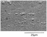
- FIG. 10 shows a cross-sectional microstructure of the material (diameter 4.5 mm) after the first plastic working, observed by a scanning electron microscope (1000-fold magnification).
- the cross-sectional microstructure in FIG. 10 was a linear processed structure in which the ⁇ phase and the ⁇ ′ phase extended in the stretching direction (the longitudinal direction of the material).
- the carbides tended to aggregate in the stretching direction. Then, no defective portion originating from carbide was found, but at this time, the first heat treatment was performed.
- FIG. 11 shows a cross-sectional microstructure of the material (4.5 mm in diameter) after the first heat treatment, observed by a scanning electron microscope (1000-fold magnification).
- FIG. 12 shows a cross-sectional microstructure of a material (diameter: 4.0 mm) after the fourth pass in the second plastic working, observed by a scanning electron microscope (1000-fold magnification).
- the cross-sectional microstructure in FIG. 12 was a linear processed structure in which the ⁇ phase and the ⁇ ′ phase extended in the stretching direction (the longitudinal direction of the material).
- the carbides tended to aggregate in the stretching direction. Then, the first heat treatment was performed at the time after the first plastic working, and no defect starting from carbide was found.
- the microstructure of the outer peripheral part and the central part by the optical microscope in the longitudinal section of the wire rod having the final dimension of the wire diameter of 1.0 mm has a ⁇ ′ phase in a granular ⁇ phase in any case as in FIG. 4B.
- a uniformly precipitated recrystallization structure was obtained.
- a carbide aggregate continued in the stretching direction was observed, but no defect was observed between the carbide particles.
- the hardness at the center of the wire having a diameter of 1.0 mm was 382 HV.
- the dimension d (1.5 mm) of the material subjected to the fifth heat treatment was 1.5 times the final product dimension d f (1.0 mm).
- the examples show that a thin wire of a Ni-based super heat-resistant alloy can be manufactured by cold plastic working.
- the Ni-based super heat-resistant alloy produced by the production method of the present invention can be worked into a wire having an arbitrary wire diameter by cold plastic working.
- the present embodiment is applied to the manufacture of a wire, it is also applicable to the manufacture of other shapes such as a plate.
Landscapes
- Chemical & Material Sciences (AREA)
- Engineering & Computer Science (AREA)
- Materials Engineering (AREA)
- Mechanical Engineering (AREA)
- Metallurgy (AREA)
- Organic Chemistry (AREA)
- Physics & Mathematics (AREA)
- Thermal Sciences (AREA)
- Crystallography & Structural Chemistry (AREA)
- Turbine Rotor Nozzle Sealing (AREA)
- Heat Treatment Of Steel (AREA)
Abstract
L'invention concerne un procédé de production d'un alliage super résistant à la chaleur à base de Ni ayant une formule compositionnelle telle que le volume d'équilibre pour des précipitations dans une phase gamma prime à 700 °C peut devenir supérieur ou égal à 35 % en moles ; et un alliage super résistant à la chaleur à base de Ni. Le procédé selon la présente invention comprend les étapes suivantes : (a) soumission d'un matériau ayant une formule compositionnelle telle que la teneur en carbone est de 0,01 à 0,25 % en masse et le volume d'équilibre pour des précipitations dans une phase gamma prime à 700 °C peut devenir 35 % en moles ou plus à une procédure de travail du plastique plusieurs fois à une température de 500 °C ou moins de telle sorte que le rapport de travail cumulé du matériau peut devenir 40 % ou plus, produisant ainsi un premier matériau travaillé ; (b) soumission du premier matériau travaillé à un traitement thermique à une température de 900 °C ou plus, produisant ainsi un premier matériau traité thermiquement ; et (c) soumission supplémentaire du premier matériau traité thermiquement à une procédure de travail du plastique une ou plusieurs fois à une température de 500 °C ou moins de telle manière que le rapport de travail cumulé du premier matériau traité thermiquement peut devenir de 10 % ou plus, ce qui permet de produire un second matériau travaillé. L'alliage super résistant à la chaleur à base de Ni selon la présente invention présente la formule compositionnelle susmentionnée, le taux de défauts dans une structure de section transversale étant de 0,5 % en surface ou moins.
Priority Applications (1)
| Application Number | Priority Date | Filing Date | Title |
|---|---|---|---|
| JP2019564552A JP6748951B2 (ja) | 2018-08-07 | 2019-07-05 | Ni基超耐熱合金の製造方法およびNi基超耐熱合金 |
Applications Claiming Priority (4)
| Application Number | Priority Date | Filing Date | Title |
|---|---|---|---|
| JP2018-148418 | 2018-08-07 | ||
| JP2018148418 | 2018-08-07 | ||
| JP2018-244048 | 2018-12-27 | ||
| JP2018244048 | 2018-12-27 |
Publications (1)
| Publication Number | Publication Date |
|---|---|
| WO2020031579A1 true WO2020031579A1 (fr) | 2020-02-13 |
Family
ID=69415470
Family Applications (1)
| Application Number | Title | Priority Date | Filing Date |
|---|---|---|---|
| PCT/JP2019/026836 Ceased WO2020031579A1 (fr) | 2018-08-07 | 2019-07-05 | Procédé de production d'un alliage super résistant à la chaleur à base de ni, et alliage super résistant à la chaleur à base de ni |
Country Status (2)
| Country | Link |
|---|---|
| JP (1) | JP6748951B2 (fr) |
| WO (1) | WO2020031579A1 (fr) |
Cited By (2)
| Publication number | Priority date | Publication date | Assignee | Title |
|---|---|---|---|---|
| KR20220138825A (ko) * | 2021-04-06 | 2022-10-13 | 다이도 토쿠슈코 카부시키가이샤 | 내열 합금 부재, 이것에 이용하는 소재 및 이들의 제조 방법 |
| CN115505788A (zh) * | 2022-09-20 | 2022-12-23 | 北京北冶功能材料有限公司 | 一种抗应变时效开裂的镍基高温合金及其制备方法和应用 |
Families Citing this family (2)
| Publication number | Priority date | Publication date | Assignee | Title |
|---|---|---|---|---|
| DE102022103420A1 (de) | 2022-02-14 | 2023-08-17 | MTU Aero Engines AG | Nickellegierung, Pulver zur Herstellung einer Nickellegierung, Bauteil, Verfahren zur Herstellung einer Nickellegierung sowie Verfahren zur Herstellung eines Bauteils |
| CN114737084A (zh) * | 2022-06-07 | 2022-07-12 | 中国航发北京航空材料研究院 | 高强抗蠕变高温合金及其制备方法 |
Citations (4)
| Publication number | Priority date | Publication date | Assignee | Title |
|---|---|---|---|---|
| US5976280A (en) * | 1993-06-10 | 1999-11-02 | United Technologies Corp. | Method for making a hydrogen embrittlement resistant γ' strengthened nickel base superalloy material |
| WO2016129485A1 (fr) * | 2015-02-12 | 2016-08-18 | 日立金属株式会社 | PROCÉDÉ DE FABRICATION D'UN ALLIAGE À HAUTE RÉSISTANCE THERMIQUE À BASE DE Ni |
| WO2018061317A1 (fr) * | 2016-09-30 | 2018-04-05 | 日立金属株式会社 | Procédé de fabrication de matériau extrudé d'alliage très résistant à la chaleur à base de ni, et matériau extrudé d'alliage très résistant à la chaleur à base de ni |
| WO2018061540A1 (fr) * | 2016-09-29 | 2018-04-05 | 日立金属株式会社 | Procédé de moulage par extrusion à chaud pour alliage à base de ni très résistant à la chaleur et procédé de production d'un matériau d'extrusion d'alliage à base de ni très résistant à la chaleur |
-
2019
- 2019-07-05 WO PCT/JP2019/026836 patent/WO2020031579A1/fr not_active Ceased
- 2019-07-05 JP JP2019564552A patent/JP6748951B2/ja active Active
Patent Citations (4)
| Publication number | Priority date | Publication date | Assignee | Title |
|---|---|---|---|---|
| US5976280A (en) * | 1993-06-10 | 1999-11-02 | United Technologies Corp. | Method for making a hydrogen embrittlement resistant γ' strengthened nickel base superalloy material |
| WO2016129485A1 (fr) * | 2015-02-12 | 2016-08-18 | 日立金属株式会社 | PROCÉDÉ DE FABRICATION D'UN ALLIAGE À HAUTE RÉSISTANCE THERMIQUE À BASE DE Ni |
| WO2018061540A1 (fr) * | 2016-09-29 | 2018-04-05 | 日立金属株式会社 | Procédé de moulage par extrusion à chaud pour alliage à base de ni très résistant à la chaleur et procédé de production d'un matériau d'extrusion d'alliage à base de ni très résistant à la chaleur |
| WO2018061317A1 (fr) * | 2016-09-30 | 2018-04-05 | 日立金属株式会社 | Procédé de fabrication de matériau extrudé d'alliage très résistant à la chaleur à base de ni, et matériau extrudé d'alliage très résistant à la chaleur à base de ni |
Cited By (3)
| Publication number | Priority date | Publication date | Assignee | Title |
|---|---|---|---|---|
| KR20220138825A (ko) * | 2021-04-06 | 2022-10-13 | 다이도 토쿠슈코 카부시키가이샤 | 내열 합금 부재, 이것에 이용하는 소재 및 이들의 제조 방법 |
| KR102684607B1 (ko) | 2021-04-06 | 2024-07-11 | 다이도 토쿠슈코 카부시키가이샤 | 내열 합금 부재, 이것에 이용하는 소재 및 이들의 제조 방법 |
| CN115505788A (zh) * | 2022-09-20 | 2022-12-23 | 北京北冶功能材料有限公司 | 一种抗应变时效开裂的镍基高温合金及其制备方法和应用 |
Also Published As
| Publication number | Publication date |
|---|---|
| JPWO2020031579A1 (ja) | 2020-08-20 |
| JP6748951B2 (ja) | 2020-09-02 |
Similar Documents
| Publication | Publication Date | Title |
|---|---|---|
| JP6889418B2 (ja) | Ni基超耐熱合金の製造方法およびNi基超耐熱合金 | |
| US11085104B2 (en) | Method for manufacturing Ni-based heat-resistant superalloy wire, and Ni-based heat-resistant super alloy wire | |
| JP6422045B1 (ja) | Ni基超耐熱合金およびその製造方法 | |
| JP6826766B1 (ja) | Ni基超耐熱合金の製造方法およびNi基超耐熱合金 | |
| JP5652730B1 (ja) | Ni基超耐熱合金及びその製造方法 | |
| JP6252704B2 (ja) | Ni基超耐熱合金の製造方法 | |
| JP6150192B2 (ja) | Ni基超耐熱合金の製造方法 | |
| JP6826879B2 (ja) | Ni基超耐熱合金の製造方法 | |
| JP6748951B2 (ja) | Ni基超耐熱合金の製造方法およびNi基超耐熱合金 | |
| JP6120200B2 (ja) | Ni基超耐熱合金およびそれを用いたタービンディスク | |
| JP6315320B2 (ja) | Fe−Ni基超耐熱合金の製造方法 | |
| JP6660042B2 (ja) | Ni基超耐熱合金押出材の製造方法およびNi基超耐熱合金押出材 | |
| JP2019183263A (ja) | 冷間加工用Ni基超耐熱合金素材 | |
| WO2017170433A1 (fr) | Procédé destiné à la production d'alliage à base de ni à très haute résistance à la chaleur | |
| JP2021011601A (ja) | Ni基超耐熱合金の製造方法 | |
| JP2020001047A (ja) | Ni基超耐熱合金溶接材 |
Legal Events
| Date | Code | Title | Description |
|---|---|---|---|
| ENP | Entry into the national phase |
Ref document number: 2019564552 Country of ref document: JP Kind code of ref document: A |
|
| 121 | Ep: the epo has been informed by wipo that ep was designated in this application |
Ref document number: 19846146 Country of ref document: EP Kind code of ref document: A1 |
|
| NENP | Non-entry into the national phase |
Ref country code: DE |
|
| 122 | Ep: pct application non-entry in european phase |
Ref document number: 19846146 Country of ref document: EP Kind code of ref document: A1 |