WO2020031621A1 - 超音波流量計 - Google Patents
超音波流量計 Download PDFInfo
- Publication number
- WO2020031621A1 WO2020031621A1 PCT/JP2019/027783 JP2019027783W WO2020031621A1 WO 2020031621 A1 WO2020031621 A1 WO 2020031621A1 JP 2019027783 W JP2019027783 W JP 2019027783W WO 2020031621 A1 WO2020031621 A1 WO 2020031621A1
- Authority
- WO
- WIPO (PCT)
- Prior art keywords
- ultrasonic
- partition plate
- measurement
- flow
- measurement channel
- Prior art date
- Legal status (The legal status is an assumption and is not a legal conclusion. Google has not performed a legal analysis and makes no representation as to the accuracy of the status listed.)
- Ceased
Links
Images
Classifications
-
- G—PHYSICS
- G01—MEASURING; TESTING
- G01F—MEASURING VOLUME, VOLUME FLOW, MASS FLOW OR LIQUID LEVEL; METERING BY VOLUME
- G01F1/00—Measuring the volume flow or mass flow of fluid or fluent solid material wherein the fluid passes through a meter in a continuous flow
- G01F1/66—Measuring the volume flow or mass flow of fluid or fluent solid material wherein the fluid passes through a meter in a continuous flow by measuring frequency, phase shift or propagation time of electromagnetic or other waves, e.g. using ultrasonic flowmeters
- G01F1/662—Constructional details
-
- G—PHYSICS
- G01—MEASURING; TESTING
- G01F—MEASURING VOLUME, VOLUME FLOW, MASS FLOW OR LIQUID LEVEL; METERING BY VOLUME
- G01F1/00—Measuring the volume flow or mass flow of fluid or fluent solid material wherein the fluid passes through a meter in a continuous flow
- G01F1/66—Measuring the volume flow or mass flow of fluid or fluent solid material wherein the fluid passes through a meter in a continuous flow by measuring frequency, phase shift or propagation time of electromagnetic or other waves, e.g. using ultrasonic flowmeters
- G01F1/667—Arrangements of transducers for ultrasonic flowmeters; Circuits for operating ultrasonic flowmeters
-
- G—PHYSICS
- G01—MEASURING; TESTING
- G01F—MEASURING VOLUME, VOLUME FLOW, MASS FLOW OR LIQUID LEVEL; METERING BY VOLUME
- G01F15/00—Details of, or accessories for, apparatus of groups G01F1/00 - G01F13/00 insofar as such details or appliances are not adapted to particular types of such apparatus
Definitions
- the present invention relates to an ultrasonic flowmeter for measuring a flow rate by dividing a measurement flow path into a multilayer flow path by a partition plate.
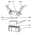
- FIG. 6 there is an ultrasonic flowmeter in which a measurement flow path 101, a plurality of partition plates 102, and a winding flow suppression sheet 103 are configured as separate components.
- the measurement flow path 101 has a component insertion port 106, and after inserting a plurality of partition plates 102 from the component insertion port 106 into the measurement flow path 101 at a predetermined angle, the component insertion port 106 is wrapped around the flow suppression sheet. Cover with 103.
- the ultrasonic sensor mounting block 104 is fixed to the measurement channel 101 by a method such as heat welding to close the component insertion port 106, and the pair of ultrasonic sensors 105a and 105b are mounted on the ultrasonic sensor mounting block 104.
- the ultrasonic flowmeter shown in FIG. 6 has a configuration in which the fluid to be measured does not leak. Further, the winding flow suppressing sheet 103 is provided with openings 103a and 103b through which ultrasonic waves pass (for example, see Patent Document 1). The reason why the partition plate 102 is provided in the measurement channel 101 is to make the flow velocity distribution of the fluid flowing in the measurement channel 101 uniform.
- Patent Literature 1 has a problem that the number of parts increases and the cost increases.
- the partition plate 102 is formed by stamping a metal plate with a metal mold, burrs and warpage occur at the time of molding, so the state is different between the front and back surfaces. Therefore, in order to improve the measurement accuracy, it is necessary to align the front and back, and a device for identifying the front and back of the partition plate 102 is required.
- the present disclosure reduces the cost as compared with the conventional configuration by integral molding of the measurement flow path and the partition plate, and, due to the draft angle of the mold generated in the partition plate due to the integral molding of the measurement flow path and the partition plate, the partition plate. It is possible to suppress the problem that the flow direction of the fluid to be measured is varied due to a deviation in the traveling direction of the reflected sound wave or separation of the fluid at the end of the partition plate. And, an ultrasonic flowmeter capable of improving the variation in measurement due to the disturbance of the received waveform caused by this problem is provided.
- An ultrasonic flowmeter includes a measurement flow path in which a cross section of a flow path through which a fluid to be measured flows is rectangular, one or more partition plates that divide the measurement flow path into a plurality of layered flow paths, A pair of ultrasonic sensors arranged upstream and downstream on the road and capable of transmitting and receiving ultrasonic signals. Further, the ultrasonic flowmeter according to the present disclosure is based on the propagation time from when the ultrasonic signal transmitted from one of the ultrasonic sensors propagates through the fluid to be measured and is received by the other ultrasonic sensor. A flow measuring unit for detecting a flow rate of the measurement fluid. Further, the measurement channel and the partition plate are integrally formed, and the partition plate is formed to have a shape that becomes thinner from a portion having the maximum thickness toward the measurement channel inlet side and the measurement channel outlet side.
- the ultrasonic flow meter reduces the number of components and reduces the cost of components compared to the related art, while the fluid to be measured is separated at the end of the partition plate, and the flow of the fluid to be measured is disturbed. This can improve the variation in measurement that occurs.
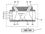
- FIG. 1 is a sectional view of the ultrasonic flow meter according to the first embodiment.
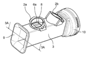
- FIG. 2 is a perspective view of a measurement flow channel of the ultrasonic flowmeter according to the first embodiment.
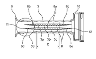
- FIG. 3A is a sectional view taken along line 3A-3A of FIG.
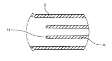
- FIG. 3B is an enlarged view of a portion 3B in FIG. 3A.
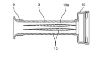
- FIG. 4 is a cross-sectional view of the ultrasonic flow meter according to the second embodiment in a direction perpendicular to a partition plate.
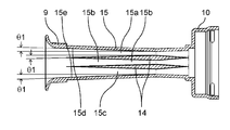
- FIG. 5 is a cross-sectional view of the ultrasonic flow meter according to the third embodiment in a direction perpendicular to the partition plate.
- FIG. 6 is an exploded perspective view of a conventional ultrasonic flowmeter.
- FIG. 1 is a cross-sectional view of the ultrasonic flow meter according to the first embodiment.
- FIG. 2 is a perspective view of a measurement flow channel of the ultrasonic flowmeter according to the first embodiment.
- FIG. 3A is a sectional view taken along line 3A-3A in FIG.
- FIG. 3B is an enlarged view of a portion 3B in FIG. 3A.
- the measurement flow path 3 for passing the measured fluid from the measurement flow path inlet 9 to the measurement flow path outlet 10 is a pipe through which the measured fluid is passed. It is divided into laminar flow paths 3a, 3b, 3c. Openings 6 a and 6 b through which ultrasonic waves propagate obliquely with respect to the measurement flow path 3 are formed on the measurement flow path upper surface 4, and the ultrasonic waves are reflected by the measurement flow path bottom surface 5.
- the ultrasonic sensors 1a and 1b are fixed to the mounting portions 2a and 2b so as to pass through the propagation paths P1 and P2.
- the flow rate measuring unit 7 calculates the flow rate based on the propagation time of the ultrasonic wave between the ultrasonic sensors 1a and 1b.
- the measurement channel 3, the partition plate 8, and the mounting portions 2a and 2b are integrally formed of resin. Thereby, the number of parts can be reduced as compared with the conventional ultrasonic flow meter, and the cost can be reduced.
- the shape of the partition plate 8 in the present embodiment is intended to increase the accuracy of flow measurement when the measurement channel 3 and the partition plate 8 are integrally molded.
- the part of the partition plate 8 from the portion 8a having the maximum thickness toward the measurement flow channel inlet 9 and the measurement flow channel outlet 10 side of the measurement flow channel 3 gradually moves toward the tips 11 and 12 of the partition plate 8. It has a thin shape.
- the partition plate 8 needs a certain thickness.
- the fluid to be measured is provided by providing sharpened portions 8b and 8c in which the thickness of the partition plate 8 is reduced from the portion 8a where the partition plate 8 has the maximum thickness toward the respective tips 11 and 12 of the partition plate 8. Can be suppressed, and the flow rate measurement can be stabilized.
- the partition plate 8 forms a plane parallel to the direction in which the fluid to be measured flows and the sound radiation direction of the ultrasonic sensors 1a and 1b.
- the partition plates 8 are formed by streamlines.
- the ultrasonic waves transmitted and received by the ultrasonic sensors 1a and 1b propagate, the ultrasonic waves are reflected on the surface of the partition plate 8, and when the reflection surface is a curved surface, the direction of reflection of the sound waves is 8, and the finally obtained reception waveform becomes unstable. Therefore, in the region C where the ultrasonic wave propagates, the partition plate 8 is formed as a plane as much as possible, and a plane parallel to the direction in which the fluid to be measured flows and the sound radiation direction of the ultrasonic sensors 1a and 1b. Variations in the received waveform are smaller than when the surface of the partition plate 8 has an inclination, and more stable measurement can be performed.
- the tip 11 of the partition plate 8 on the measurement channel inlet 9 side may be a curved surface.
- the tip 12 of the partition plate 8 on the measurement flow path outlet 10 side may be a curved surface.
- a teardrop-shaped cross-sectional shape with a rounded front edge and a sharpened rear edge is said to have the least fluid separation and low resistance.
- a backflow also occurs. If the trailing edge is thin and sharp, a backflow occurs, and the angle of the inflow of the fluid to be measured deviates from the angle of the partition plate. At the trailing edge, separation of the fluid to be measured occurs at the trailing edge. For this reason, the flow in the region where the ultrasonic wave measured by the ultrasonic sensor propagates is disturbed, and a difference may occur in the flow measurement value between the forward flow and the backward flow.
- the tip of the partition plate 8 is made to be an acute angle, a short shot in which the resin does not enter into the tip at the time of molding occurs, and the tip shape becomes uneven, which may also cause a disturbance in the flow of the fluid to be measured. For this reason, more stable flow rate measurement can be performed by making the tips 11 and 12 of the partition plates 8 on both the measurement channel inlet 9 side and the measurement channel outlet 10 side curved.
- FIG. 4 is a cross-sectional view of the ultrasonic flowmeter according to the second embodiment in a direction perpendicular to a partition plate.
- a cross-sectional view in a direction parallel to the partition plate 8 is the same as FIG.
- the thickness portion 13a is closer to the rear edge (measurement flow path exit 10 side) than the front edge (measurement flow path entrance 9 side), not the middle point of the partition plate 13.
- the ultrasonic flow meter according to the present embodiment can suppress the separation of the fluid in the region where the ultrasonic wave is measured in the case of the forward flow, and can perform more stable measurement.
- the measurement area of the ultrasonic sensors 1a and 1b (area where ultrasonic waves propagate), if the surface of the partition plate 13 has a curved surface, the reflection direction of the sound wave depends on where on the partition plate 13 the light is reflected. On the other hand, since the reception waveform becomes unstable, the measurement area of the ultrasonic sensors 1a and 1b may be formed as a flat surface without providing a curved surface as much as possible.
- FIG. 5 is a cross-sectional view of the ultrasonic flow meter according to the third embodiment in a direction perpendicular to the partition plate.
- a cross-sectional view in the direction parallel to the partition plate 14 is the same as FIG.
- the inner walls 15 d and 15 e parallel to the partition plate 14 are provided with gradients that are symmetric with the gradient of the opposing partition plate 14. That is, in order to make the shape of the three layered flow paths 15a, 15b, 15c formed by dividing the measurement flow path 15 by the two partition plates 14, the draft ⁇ 1 provided in the partition plate 14 The same gradient is provided on the inner walls 15d and 15e of the flow path.
- the present disclosure it is possible to reduce the cost as compared with the conventional configuration by integrally molding the measurement flow path and the partition plate, and to remove the die generated in the partition plate due to the integral molding of the measurement flow path and the partition plate. It is a gradient. Due to this configuration, the traveling direction of the sound wave reflected by the partition plate is deviated, or the flow of the fluid to be measured is varied due to the separation of the fluid at the end of the partition plate, and the measurement due to the disturbance of the received waveform is performed. Variation can be improved.
- the ultrasonic flowmeter includes a measurement flow channel having a rectangular cross-section of a flow channel through which a fluid to be measured flows, and one or more measurement flow channels that divide the measurement flow channel into a plurality of layered flow channels. And a pair of ultrasonic sensors disposed upstream and downstream of the laminar flow path and capable of transmitting and receiving ultrasonic signals. Further, the ultrasonic flow meter according to the present disclosure is based on the propagation time until the ultrasonic signal transmitted from one of the ultrasonic sensors propagates through the fluid to be measured and is received by the other ultrasonic sensor. A flow rate measuring unit for detecting a flow rate. Further, the measurement channel and the partition plate are integrally formed, and the partition plate is formed to have a shape that becomes thinner from a portion having the maximum thickness toward the measurement channel inlet side and the measurement channel outlet side.
- the ultrasonic flowmeter according to the first disclosure reduces the number of components and reduces the cost of components compared to the conventional one, while the fluid to be measured is separated at the end of the partition plate, and the flow of the fluid to be measured is reduced. Can be improved due to the fluctuation of the measurement.
- a portion having a maximum thickness is configured by a surface parallel to a flowing direction of a fluid to be measured and a radiation direction of sound of the ultrasonic sensor, It may include at least a part of a region where the sound wave transmitted by the ultrasonic sensor propagates.
- the ultrasonic flowmeter makes the propagation of the sound wave in the measurement area measured by the ultrasonic wave and the flow of the fluid to be measured uniform, and can perform more stable measurement.
- At least the distal end of the partition plate on the measurement channel entrance side may be configured to have a curved surface.
- the ultrasonic flowmeter according to the third disclosure narrows the end of the partition plate while suppressing a short shot generated at the tip of the partition plate during molding, and suppresses the turbulence of the flow of the fluid to be measured. And more stable measurement can be performed.
- At least the tip of the partition plate on the measurement channel inlet side may be configured to have a curved surface.
- the ultrasonic flowmeter according to the fourth disclosure narrows the end of the partition plate while suppressing a short shot generated at the tip of the partition plate at the time of molding, and suppresses the turbulence of the flow of the fluid to be measured. And more stable measurement can be performed.
- a portion where a maximum thickness of the partition plate is at a midpoint of a propagation path in a measurement flow path of the ultrasonic sensor. May be closer to the measurement channel outlet side.
- the ultrasonic flow meter according to the fifth disclosure can suppress the separation of the fluid in the region where the ultrasonic wave is measured in the case of the forward flow, and can perform more stable measurement.
- the ultrasonic flowmeter is adapted to the shape of the partition plate such that the shape of the plurality of layered flow channels of the measurement flow channel is the same. May have a gradient.
- the ultrasonic flowmeter according to the seventh disclosure may have a gradient according to the shape of the partition plate so that the shape of the plurality of laminar flow channels of the measurement flow channel is particularly the same as in the fifth disclosure. Good.
- the ultrasonic flowmeter according to the eighth disclosure is, in particular, according to any one of the first to fourth disclosures, further including a sensor mounting portion for mounting an ultrasonic sensor, and includes a measurement channel, a partition plate, and a sensor mounting portion.
- the part may be integrally molded.
- the ultrasonic flowmeter according to the ninth disclosure in particular, according to the fifth disclosure, further includes a sensor mounting portion for mounting an ultrasonic sensor, and the measurement channel, the partition plate, and the sensor mounting portion are integrally formed. Is also good.
- the ultrasonic flow meter according to the tenth disclosure is, in particular, provided in the sixth disclosure, further comprising a sensor mounting portion for mounting an ultrasonic sensor, and integrally forming the measurement flow path, the partition plate, and the sensor mounting portion. Is also good.
- the ultrasonic flowmeter according to the eleventh disclosure is particularly characterized in that, in the seventh disclosure, the ultrasonic flowmeter further includes a sensor mounting portion for mounting an ultrasonic sensor, and the measurement channel, the partition plate, and the sensor mounting portion are integrally formed. Is also good.
- the ultrasonic flowmeter according to the present disclosure is caused by the fact that the fluid to be measured is peeled off at the end of the partition plate and the flow of the fluid to be measured is disturbed while reducing the cost of the parts that have conventionally occurred. Since it is possible to improve the variation in measurement due to the thickness, it can be applied to uses such as a gas meter.
Landscapes
- Physics & Mathematics (AREA)
- Fluid Mechanics (AREA)
- General Physics & Mathematics (AREA)
- Electromagnetism (AREA)
- Measuring Volume Flow (AREA)
Priority Applications (6)
| Application Number | Priority Date | Filing Date | Title |
|---|---|---|---|
| EP19847012.2A EP3835733B1 (de) | 2018-08-08 | 2019-07-12 | Ultraschallflussmesser |
| US17/256,452 US11686604B2 (en) | 2018-08-08 | 2019-07-12 | Ultrasonic flow meter having one or more integrally molded partition plates dividing the measurement path and having thinner upstream and downstream edges |
| ES19847012T ES2940772T3 (es) | 2018-08-08 | 2019-07-12 | Caudalímetro ultrasónico |
| CN202411320354.4A CN119197668A (zh) | 2018-08-08 | 2019-07-12 | 超声波流量计 |
| CN201980052050.5A CN112534213B (zh) | 2018-08-08 | 2019-07-12 | 超声波流量计 |
| PL19847012.2T PL3835733T3 (pl) | 2018-08-08 | 2019-07-12 | Przepływomierz ultradźwiękowy |
Applications Claiming Priority (2)
| Application Number | Priority Date | Filing Date | Title |
|---|---|---|---|
| JP2018148964A JP7126048B2 (ja) | 2018-08-08 | 2018-08-08 | 超音波流量計 |
| JP2018-148964 | 2018-08-08 |
Publications (1)
| Publication Number | Publication Date |
|---|---|
| WO2020031621A1 true WO2020031621A1 (ja) | 2020-02-13 |
Family
ID=69414735
Family Applications (1)
| Application Number | Title | Priority Date | Filing Date |
|---|---|---|---|
| PCT/JP2019/027783 Ceased WO2020031621A1 (ja) | 2018-08-08 | 2019-07-12 | 超音波流量計 |
Country Status (8)
| Country | Link |
|---|---|
| US (1) | US11686604B2 (de) |
| EP (1) | EP3835733B1 (de) |
| JP (1) | JP7126048B2 (de) |
| CN (2) | CN119197668A (de) |
| ES (1) | ES2940772T3 (de) |
| PL (1) | PL3835733T3 (de) |
| PT (1) | PT3835733T (de) |
| WO (1) | WO2020031621A1 (de) |
Cited By (2)
| Publication number | Priority date | Publication date | Assignee | Title |
|---|---|---|---|---|
| IT202200003077A1 (it) | 2022-02-18 | 2023-08-18 | Pietro Fiorentini Spa | Dispositivo perfezionato per la misura di un fluido, preferibilmente di un gas. |
| IT202200008975A1 (it) | 2022-05-03 | 2023-11-03 | Pietro Fiorentini Spa | Dispositivo perfezionato per la misura di un fluido, preferibilmente di un gas. |
Families Citing this family (3)
| Publication number | Priority date | Publication date | Assignee | Title |
|---|---|---|---|---|
| JP7620927B2 (ja) * | 2022-02-21 | 2025-01-24 | パナソニックIpマネジメント株式会社 | 超音波流量計 |
| CN115265684B (zh) * | 2022-07-27 | 2024-03-15 | 杭州思筑智能设备有限公司 | 一种带渐变条状格栅的反射型扁平流道及流量计系统 |
| CN115200658B (zh) * | 2022-07-27 | 2024-12-20 | 杭州思筑智能设备有限公司 | 一种带超声波陷阱结构的扁平流道及流量计系统 |
Citations (3)
| Publication number | Priority date | Publication date | Assignee | Title |
|---|---|---|---|---|
| JP2004170384A (ja) * | 2002-11-01 | 2004-06-17 | Matsushita Electric Ind Co Ltd | 流体の流れ計測装置 |
| JP2004316685A (ja) * | 2003-04-11 | 2004-11-11 | Yazaki Corp | 流路ユニット、積層部及び当該積層部の製造方法 |
| JP2014215060A (ja) | 2013-04-23 | 2014-11-17 | パナソニック株式会社 | 流量計測装置 |
Family Cites Families (19)
| Publication number | Priority date | Publication date | Assignee | Title |
|---|---|---|---|---|
| FR2683046B1 (fr) * | 1991-10-25 | 1994-02-04 | Schlumberger Industries | Dispositif de mesure de la vitesse d'un fluide. |
| US5600073A (en) * | 1994-11-02 | 1997-02-04 | Foster-Miller, Inc. | Method and system for analyzing a two phase flow |
| JP3398251B2 (ja) * | 1995-03-08 | 2003-04-21 | 東京瓦斯株式会社 | 流量計 |
| UA51734C2 (uk) * | 1996-10-03 | 2002-12-16 | Візувіус Крусібл Компані | Занурений стакан для пропускання рідкого металу і спосіб пропускання рідкого металу через нього |
| EP1612520B1 (de) * | 2003-02-24 | 2019-01-16 | Panasonic Corporation | Fluidmesseinrichtung des ultraschalltyps |
| CA2439242C (en) * | 2003-09-03 | 2008-01-29 | Photon Control Inc. | Optical flow meter for measuring gases and liquids in pipelines |
| DE102004060065B4 (de) | 2004-12-14 | 2016-10-20 | Robert Bosch Gmbh | Ultraschall Durchflussmesser mit Leitelementen |
| CN100533046C (zh) * | 2006-09-29 | 2009-08-26 | 汉拏空调株式会社 | 用于热交换器的板 |
| EP2343516A4 (de) * | 2008-11-05 | 2012-05-02 | Panasonic Corp | Mehrschichtiges kanalelement und ultraschall-flüssigkeitsmessvorrichtung damit |
| JP2011112378A (ja) * | 2009-11-24 | 2011-06-09 | Panasonic Corp | 流路部材および超音波式流体計測装置 |
| JP5712358B2 (ja) * | 2009-11-24 | 2015-05-07 | パナソニックIpマネジメント株式会社 | 超音波式流体計測構造および超音波式流体計測装置 |
| RU2422777C1 (ru) | 2010-01-29 | 2011-06-27 | Александр Михайлович Деревягин | Ультразвуковой способ измерения расхода жидких и/или газообразных сред и устройство для его осуществления |
| JP2012247299A (ja) * | 2011-05-27 | 2012-12-13 | Panasonic Corp | 超音波式流量計測ユニットおよびこれを用いたガス流量計 |
| JP5815437B2 (ja) * | 2012-02-28 | 2015-11-17 | アズビル株式会社 | 超音波流体測定装置 |
| JP6028215B2 (ja) * | 2012-03-09 | 2016-11-16 | パナソニックIpマネジメント株式会社 | 超音波流量計 |
| GB2504295B (en) * | 2012-07-24 | 2019-07-31 | Titan Entpr Ltd | Flowmeter with annular passage |
| EP2787329B1 (de) * | 2013-04-04 | 2017-02-15 | Nanjing Youyang Control Technology Co. Ltd | Messen eines flusses eines fluids durch einen zylinderförmigen rohrabschnitt |
| JP6362548B2 (ja) * | 2014-04-30 | 2018-07-25 | ニチアス株式会社 | ウォータジャケット用スペーサの製造方法 |
| JP5898369B1 (ja) * | 2015-11-16 | 2016-04-06 | 東京計装株式会社 | 超音波流量計 |
-
2018
- 2018-08-08 JP JP2018148964A patent/JP7126048B2/ja active Active
-
2019
- 2019-07-12 US US17/256,452 patent/US11686604B2/en active Active
- 2019-07-12 EP EP19847012.2A patent/EP3835733B1/de active Active
- 2019-07-12 PL PL19847012.2T patent/PL3835733T3/pl unknown
- 2019-07-12 ES ES19847012T patent/ES2940772T3/es active Active
- 2019-07-12 CN CN202411320354.4A patent/CN119197668A/zh active Pending
- 2019-07-12 CN CN201980052050.5A patent/CN112534213B/zh active Active
- 2019-07-12 PT PT198470122T patent/PT3835733T/pt unknown
- 2019-07-12 WO PCT/JP2019/027783 patent/WO2020031621A1/ja not_active Ceased
Patent Citations (3)
| Publication number | Priority date | Publication date | Assignee | Title |
|---|---|---|---|---|
| JP2004170384A (ja) * | 2002-11-01 | 2004-06-17 | Matsushita Electric Ind Co Ltd | 流体の流れ計測装置 |
| JP2004316685A (ja) * | 2003-04-11 | 2004-11-11 | Yazaki Corp | 流路ユニット、積層部及び当該積層部の製造方法 |
| JP2014215060A (ja) | 2013-04-23 | 2014-11-17 | パナソニック株式会社 | 流量計測装置 |
Non-Patent Citations (1)
| Title |
|---|
| See also references of EP3835733A4 |
Cited By (2)
| Publication number | Priority date | Publication date | Assignee | Title |
|---|---|---|---|---|
| IT202200003077A1 (it) | 2022-02-18 | 2023-08-18 | Pietro Fiorentini Spa | Dispositivo perfezionato per la misura di un fluido, preferibilmente di un gas. |
| IT202200008975A1 (it) | 2022-05-03 | 2023-11-03 | Pietro Fiorentini Spa | Dispositivo perfezionato per la misura di un fluido, preferibilmente di un gas. |
Also Published As
| Publication number | Publication date |
|---|---|
| EP3835733B1 (de) | 2023-03-01 |
| PT3835733T (pt) | 2023-03-14 |
| EP3835733A4 (de) | 2021-09-08 |
| ES2940772T3 (es) | 2023-05-11 |
| JP2020024149A (ja) | 2020-02-13 |
| CN119197668A (zh) | 2024-12-27 |
| PL3835733T3 (pl) | 2023-06-19 |
| CN112534213B (zh) | 2024-11-15 |
| JP7126048B2 (ja) | 2022-08-26 |
| US20210270649A1 (en) | 2021-09-02 |
| EP3835733A1 (de) | 2021-06-16 |
| CN112534213A (zh) | 2021-03-19 |
| US11686604B2 (en) | 2023-06-27 |
Similar Documents
| Publication | Publication Date | Title |
|---|---|---|
| WO2020031621A1 (ja) | 超音波流量計 | |
| JP3877777B2 (ja) | 流れ媒体の質量を測定する装置 | |
| JP4186645B2 (ja) | 超音波流量計測装置 | |
| US11802782B2 (en) | Ultrasonic flowmeter with a flow path inner wall surface with a draft of a mold for integral molding | |
| US20210293593A1 (en) | Ultrasonic flow meter | |
| JP5816831B2 (ja) | 超音波流量計 | |
| CN112050874A (zh) | 超声波流量测量计、其在闭塞器具中的使用和闭塞器具 | |
| JP6028215B2 (ja) | 超音波流量計 | |
| JP7660328B2 (ja) | 超音波流量計 | |
| JP6982737B2 (ja) | 超音波流量計 | |
| JP3689975B2 (ja) | 超音波式流量計 | |
| JP6496905B2 (ja) | 超音波流量計 | |
| EP4484902A1 (de) | Ultraschall-durchflussmesser | |
| JP7373772B2 (ja) | 物理量計測装置 | |
| JP2009109239A (ja) | 超音波流量計 | |
| JP2019191040A (ja) | 超音波流量計 | |
| JP3053444B2 (ja) | フルイディック流量計 | |
| JP2019196968A (ja) | 超音波流量計 |
Legal Events
| Date | Code | Title | Description |
|---|---|---|---|
| 121 | Ep: the epo has been informed by wipo that ep was designated in this application |
Ref document number: 19847012 Country of ref document: EP Kind code of ref document: A1 |
|
| NENP | Non-entry into the national phase |
Ref country code: DE |
|
| ENP | Entry into the national phase |
Ref document number: 2019847012 Country of ref document: EP Effective date: 20210309 |