WO2020031640A1 - Pneu de motocyclette - Google Patents
Pneu de motocyclette Download PDFInfo
- Publication number
- WO2020031640A1 WO2020031640A1 PCT/JP2019/028128 JP2019028128W WO2020031640A1 WO 2020031640 A1 WO2020031640 A1 WO 2020031640A1 JP 2019028128 W JP2019028128 W JP 2019028128W WO 2020031640 A1 WO2020031640 A1 WO 2020031640A1
- Authority
- WO
- WIPO (PCT)
- Prior art keywords
- tire
- side wall
- land portion
- land
- motorcycle
- Prior art date
- Legal status (The legal status is an assumption and is not a legal conclusion. Google has not performed a legal analysis and makes no representation as to the accuracy of the status listed.)
- Ceased
Links
Images


Classifications
-
- B—PERFORMING OPERATIONS; TRANSPORTING
- B60—VEHICLES IN GENERAL
- B60C—VEHICLE TYRES; TYRE INFLATION; TYRE CHANGING; CONNECTING VALVES TO INFLATABLE ELASTIC BODIES IN GENERAL; DEVICES OR ARRANGEMENTS RELATED TO TYRES
- B60C11/00—Tyre tread bands; Tread patterns; Anti-skid inserts
- B60C11/03—Tread patterns
- B60C11/0311—Patterns comprising tread lugs arranged parallel or oblique to the axis of rotation
-
- B—PERFORMING OPERATIONS; TRANSPORTING
- B60—VEHICLES IN GENERAL
- B60C—VEHICLE TYRES; TYRE INFLATION; TYRE CHANGING; CONNECTING VALVES TO INFLATABLE ELASTIC BODIES IN GENERAL; DEVICES OR ARRANGEMENTS RELATED TO TYRES
- B60C11/00—Tyre tread bands; Tread patterns; Anti-skid inserts
- B60C11/03—Tread patterns
- B60C11/0302—Tread patterns directional pattern, i.e. with main rolling direction
-
- B—PERFORMING OPERATIONS; TRANSPORTING
- B60—VEHICLES IN GENERAL
- B60C—VEHICLE TYRES; TYRE INFLATION; TYRE CHANGING; CONNECTING VALVES TO INFLATABLE ELASTIC BODIES IN GENERAL; DEVICES OR ARRANGEMENTS RELATED TO TYRES
- B60C11/00—Tyre tread bands; Tread patterns; Anti-skid inserts
- B60C11/03—Tread patterns
- B60C11/032—Patterns comprising isolated recesses
-
- B—PERFORMING OPERATIONS; TRANSPORTING
- B60—VEHICLES IN GENERAL
- B60C—VEHICLE TYRES; TYRE INFLATION; TYRE CHANGING; CONNECTING VALVES TO INFLATABLE ELASTIC BODIES IN GENERAL; DEVICES OR ARRANGEMENTS RELATED TO TYRES
- B60C11/00—Tyre tread bands; Tread patterns; Anti-skid inserts
- B60C11/03—Tread patterns
- B60C11/0327—Tread patterns characterised by special properties of the tread pattern
- B60C11/033—Tread patterns characterised by special properties of the tread pattern by the void or net-to-gross ratios of the patterns
-
- B—PERFORMING OPERATIONS; TRANSPORTING
- B60—VEHICLES IN GENERAL
- B60C—VEHICLE TYRES; TYRE INFLATION; TYRE CHANGING; CONNECTING VALVES TO INFLATABLE ELASTIC BODIES IN GENERAL; DEVICES OR ARRANGEMENTS RELATED TO TYRES
- B60C11/00—Tyre tread bands; Tread patterns; Anti-skid inserts
- B60C11/03—Tread patterns
- B60C11/11—Tread patterns in which the raised area of the pattern consists only of isolated elements, e.g. blocks
-
- B—PERFORMING OPERATIONS; TRANSPORTING
- B60—VEHICLES IN GENERAL
- B60C—VEHICLE TYRES; TYRE INFLATION; TYRE CHANGING; CONNECTING VALVES TO INFLATABLE ELASTIC BODIES IN GENERAL; DEVICES OR ARRANGEMENTS RELATED TO TYRES
- B60C2200/00—Tyres specially adapted for particular applications
- B60C2200/10—Tyres specially adapted for particular applications for motorcycles, scooters or the like
-
- B—PERFORMING OPERATIONS; TRANSPORTING
- B60—VEHICLES IN GENERAL
- B60C—VEHICLE TYRES; TYRE INFLATION; TYRE CHANGING; CONNECTING VALVES TO INFLATABLE ELASTIC BODIES IN GENERAL; DEVICES OR ARRANGEMENTS RELATED TO TYRES
- B60C2200/00—Tyres specially adapted for particular applications
- B60C2200/14—Tyres specially adapted for particular applications for off-road use
Definitions
- the present invention relates to a tire for a motorcycle, and more particularly, to a tire for a motorcycle in which uneven wear in use on a pavement road surface is suppressed without impairing steering stability on an uneven road surface or a pavement road surface.
- tires for motorcycles are divided into a plurality of grooves on a tread in order to secure traveling performance such as steering stability on irregular terrain.
- a number of land areas are located.
- the motorcycle tire described in Patent Literature 1 has a slope on a stepping side wall of a land portion in order to maintain good running performance by a land portion under running conditions on a bad road such as a motocross race.
- a bad road such as a motocross race.
- an object of the present invention is to provide a motorcycle tire that suppresses occurrence of uneven wear in use on a pavement road surface without impairing steering stability on an uneven road surface or a pavement road surface.
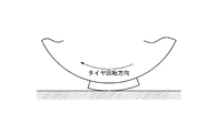
- motorcycle tires generally have a semicircular cross section having a larger curvature than that of four-wheeled vehicle tires. It has been newly discovered that when traveling straight on, the central portion of the tread comes into contact with the ground, and particularly in a land portion arranged at the central portion of the tread, preferential wear is likely to occur on one side in the circumferential direction of the tire. Furthermore, the inventor has found that by devising the shape of the side wall extending in the direction crossing the circumferential direction of the land portion, such preferential wear can be prevented and occurrence of uneven wear can be suppressed, and the present invention is completed. Reached.
- the motorcycle tire of the present invention has a plurality of width directions extending in the tire width direction at a center portion, which is a region of 50% of the length in the tire width direction along the periphery of the tread surface of the tire and centered on the tire equatorial plane.
- a motorcycle tire having one or more land portions defined by a groove and a plurality of circumferential grooves extending in a circumferential direction of the tire and having a designated rotation direction, at least one of the land portions has a circumference of the tire.
- the cross section in the direction with respect to an imaginary line connecting each of the boundaries between the side walls on the kicking side and the stepping side in the tire rotation direction facing the width direction groove of the land portion and the bottom of the width direction groove at the shortest.
- the inclination angle of the side wall on the kick side with respect to the reference line is the land portion.
- the angle is ⁇ 10 ° or more and 5 ° or less
- the inclination angle of the side wall on the kicking side is a boundary between the surface of the land portion and the side wall on the stepping side of the perpendicular. Is smaller than the inclination angle of the side wall on the stepping side with respect to a line segment passing through.
- pattern pitch in the present specification refers to the length in the tire circumferential direction per unit of a tread pattern repeated in the tire circumferential direction, and the length in the tire circumferential direction per unit changes in the tire circumferential direction. If so, it shall mean the average length.
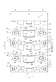
- FIG. 1 is a view showing a part of a tread surface of a tire according to an embodiment of the present invention, which is developed in a tire width direction.
- FIG. 2 is a diagram showing a cross section taken along line II-II of FIG. 1. It is a figure showing the state where the central part of the land part touched down at the time of load rolling of a tire.
- FIG. 3B is a diagram showing a state where the contact area has shifted from the state of FIG. 3A.
- FIG. 1 shows a part of a tread tread surface 2 of a tire 1 according to an embodiment of the present invention developed in a tire width direction.
- the tire 1 has a carcass straddling between a pair of bead portions as a skeleton, a pair of sidewall portions on the tire radial direction outside of the bead portion, and a tread straddling between the sidewall portions. have.
- the tire 1 is a tire whose rotation direction is specified in the direction of the arrow in the illustrated example.
- a center portion TC is a region of 50% of the length w1 in the tire width direction along the periphery of the tread tread surface 2 of the tire 1 centered on the tire equatorial plane CL.
- the tread edge TE side of the center portion TC is defined as a shoulder portion TS.
- a plurality of width direction grooves extending in the tire width direction W, 3a and 3b in the illustrated example, and a plurality of circumferential grooves extending along the tire circumferential direction, in the illustrated example, the width direction grooves 3a and 3b. It has a plurality of land portions 5a and 5b partitioned by communicating circumferential grooves 4a, 4b, 14a and 14b.
- FIG. 2 is a cross-sectional view taken along the line II-II of FIG. 1 and shows a cross section along the circumferential direction Y of the tire.
- the inclination angle ⁇ 1 with respect to the line segment L2 is ⁇ 10 ° or more and 5 ° or less when the direction inclining toward the land portion 5a is minus.
- FIGS. 3A and 3B show the deformation behavior of the land portion when the tire is rolling.
- the center of the land portion touches the road surface after stepping on, and the contact area shifts from here to the state shown in FIG. 3B.
- a crushing deformation as shown by oblique lines occurs.
- the crushing deformation is a state in which the land portion is compressed in the tire radial direction and the tread rubber swells in the tire circumferential direction or the tire width direction. When this occurs, the portion protruding due to the crushing deformation is worn together with the land portion surface, thereby causing uneven wear on the land portion.
- the inclination angle ⁇ 1 of the side wall 50A on the kick-out side is set to 5 ° or less, the amount of rubber existing outside the reference line is reduced, and the bulging to the width direction groove side is suppressed. The preferential wear of the swollen portion due to the crushing deformation can be avoided. Furthermore, by setting the inclination angle ⁇ 1 to ⁇ 10 ° or more, the rigidity of the land portion 5a is sufficiently maintained, so that the grip with the road surface is exhibited, and the land portion 5a is prevented from being chipped or scorched. be able to. By setting the inclination angle ⁇ 1 to ⁇ 10 ° or more, sufficient durability can be imparted to land portions.
- ⁇ 1 is preferably -5 ° or more and 4 ° or less, and more preferably -5 ° or more and 0 ° or less. In particular, when ⁇ 1 is set to 0 ° or less, bulging due to crushing deformation can be effectively suppressed.
- the inclination angle ⁇ 1 of the side wall 50A is smaller than the inclination angle ⁇ 2 of the side wall 50B with respect to a line L3 passing through the boundary v2 between the surface 5s of the land portion 5a and the side wall 50B, of the perpendicular to the virtual line L1. It is important. According to the above configuration, it is possible to enhance the effect of suppressing uneven wear of the land portion by avoiding the crushing deformation due to the inclination angle of the side wall 50A, and it is possible to prevent the land portion 5a from being chipped or scorched. .
- the inclination angle ⁇ 2 of the side wall 50B is not less than 10 ° and not more than 30 °. By setting the inclination angle ⁇ 2 of the side wall 50B on the stepping side in the tire rotation direction to 10 ° or more, sufficient rigidity can be imparted to the land portion 5a. Ability can be exhibited.
- the dimensions of the land portions 5a and 5b are arbitrary, but the land portion 5a will be exemplified below as a typical example.
- the surface 5s of the land portion 5a preferably has a maximum length y1 in the tire circumferential direction Y of 10 mm or more and 55 mm or less.
- a maximum length y1 in the tire circumferential direction Y of 10 mm or more and 55 mm or less.
- the maximum length y1 By setting the maximum length y1 to 10 mm or more, sufficient rigidity can be imparted to the land portion 5a and steering stability can be enhanced.
- By setting the maximum length y1 to 55 mm or less drainage and soil discharging properties are maintained.
- it is 11 mm or more and 50 mm or less, more preferably 12 mm or more and 45 mm or less.
- the maximum length w2 of the land portion 5a in the width direction of the tread tread 2 along the peripheral is preferably 10% or more and 40% or less of the width w1 of the tread tread 2 along the peripheral.
- the maximum length w2 is preferably 10% or more of the width w1 in the width direction, sufficient rigidity can be imparted to the land portion 5a, and the steering stability can be enhanced. Can maintain drainage.
- the maximum length in the tire width direction W of the land portion 5a and the land portion 5b is different from the viewpoint of the balance between drainage and rigidity, but may be the same.
- the maximum height h1 of the land portion 5a is preferably 6 mm or more and 9 mm or less.
- the maximum height h1 of the land portion 5a indicates the maximum distance from the bottoms u1 and u2 to the surface 5s.
- the grip force with the road surface can be increased, and by setting the maximum height h1 to 9 mm or less, the rigidity of the land portions 5a and 5b can be increased.
- the maximum height h1 is 7 mm or more and 9 mm or less. By setting the maximum height h1 to 9 mm or less, the absolute amount of crushing deformation of the land portion 5a can be reduced.
- the side wall 50A on the kicking-out side is arc-shaped convex to the outside of the land portion 5a on the kicking-out side in the tire rotation direction, and the side wall 50B on the stepping side is kicked in the tire rotation direction. It is preferable that it is an arc shape that protrudes inward of the land portion 5a on the delivery side. According to such a configuration, uneven wear can be more effectively suppressed in the side wall 50A on the kick-out side, and the side wall 50B on the step-in side has an arc shape that is concave with respect to the tire rotation direction. In addition, on an uneven terrain surface, soil and mud on the road surface can be effectively captured, and grip on the road surface can be improved.
- the side walls 50A and 50B extend in the tire width direction W with the same radius of curvature, but by having different radii of curvature, from the tire equatorial plane CL toward the tread end TW.
- the land portion width in the tire circumferential direction Y may be gradually increased or decreased.
- the land portion 5b has side walls 50C and 50D facing the width direction grooves 3b and 3a.
- the side walls 50A and 50B one or both sides of the kick side and the step side in the tire rotation direction can be formed in an arc shape convex to the kick side or the step side.
- the side wall 50C on the kicking-out side be formed in an arc shape convex toward the kicking-out side in the tire rotation direction.
- the land portion having an arc-shaped side wall is preferably 30% or more of the total number of land portions arranged in the center portion TC over the entire circumference of the tire 1.
- the ratio of the number of land portions 5a in which the side walls 50A and 50B are arc-shaped and the number of land portions 5b in which the side walls 50C and 50D are arc-shaped out of the total number of land portions arranged in the center portion TC is 30. % Is preferable.
- land portions other than the land portions 5a and 5b may be arranged in the center portion TC, but it is assumed that only the land portions entirely located in the center portion TC are included in the calculation.
- the contact pressure of the center portion TC tends to be particularly high, it is important to suppress uneven wear and enhance grip with a road surface by arranging a land portion having an arc-shaped side wall over a certain amount.
- the above ratio is more preferably 40% or more, and even more preferably, all of the land portions 5a and 5b arranged in the center portion TC are land portions whose side walls are arc-shaped.
- the land portions entirely located in the center portion TC are only the land portions 5a and 5b, and all the land portions have a configuration in which the side walls are arc-shaped.
- the shoulder portion TS is defined by widthwise grooves 3a and 3b extending in the tire width direction W and circumferential grooves 4a, 4b, 10a and 10b extending in the tire circumferential direction Y. have.
- the shoulder land portions 6a and 6b are arranged adjacent to both sides of the land portion 5a.
- the side wall 60A and the side wall 60C facing the width direction groove 3a of the shoulder land portions 6a and 6b extend on the same arc of the side wall 50A, that is, on the arc r1.
- the side walls 60B and 60D facing the width direction groove 3b of the shoulder land portions 6a and 6b extend on the same arc of the side wall 50B, that is, on the arc r2.
- shoulder land portions 8a and 8b which are defined by the width direction grooves 3a and 3b and the circumferential direction grooves 14a, 14b, 9a and 9b extending in the tire circumferential direction Y, are arranged in the shoulder portion TS. Further, shoulder land portions 7a and 7b defined by the width direction grooves 3a and 3b, the circumferential direction grooves 9a and 9b extending in the tire circumferential direction Y, and the tread end TE are arranged.
- the shape of the side wall of the shoulder land portions 6a, 6b, 7a, 7b, 8a and 8b facing the width direction groove is not particularly limited, but the inclination angle may be defined similarly to the land portions 5a and 5b.
- the shoulder land portions 6a, 6b, 7a, and 7b may include shallow grooves 11a, 11b, 11c, and 11d on tread treads, respectively.
- the shallow groove means that the maximum groove width is 0.1 mm or more and 2.0 mm or less, preferably 0.5 mm or more and 1.5 mm or less, and the maximum groove depth is 0.1 mm or more and 2 mm or less.
- the land portion 5a and the shoulder land portions 6a and 6b are arranged symmetrically with respect to the tire equatorial plane CL from the viewpoint of steering stability, and similarly, the land portion 5b, the shoulder land portion 7a, 7b, 8a and 8b are also arranged symmetrically with respect to the tire equatorial plane CL as an axis, but may be arranged in different shapes and phases around the equatorial plane CL.
- the number of land portions disposed between the tread ends TE, which is sandwiched between the width direction grooves 3a and 3b is one or more and seven or less. More preferably, it is two or more and six or less, and still more preferably three or more and five or less. In the illustrated example, three land portions sandwiched between the width direction grooves 3a and 3b, rows in which the land portions 5a, 6a and 6b are arranged, and five land portions sandwiched between the width direction grooves 3b and 3a. The row where the land portions, land portions 5b, 7a, 7b, 8a and 8b are arranged, is shown.
- the ratio of the area excluding the surface of the land portion to the total area of the tread surface 2 in plan view is preferably 55% or more and 70% or less.
- land portions 5a and 5b are arranged in the center portion TC, and a part of the shoulder land portions 6a, 6b, 8a and 8b is present.
- the ratio of the area is calculated based on the surface area existing in the center part TC. As described above, by setting the ratio of the area excluding the surface of the land portion to 55% or more of the total area, it is possible to maintain driving performance such as steering stability even on an irregular road surface, and to 70% or less. By doing so, it is possible to exert grip on the pavement road surface and to maintain steering stability.
- the pattern pitch in the tire circumferential direction Y is preferably 12 or more.
- the tire 1 is first arranged along the tire circumferential direction Y.
- the length p1 in the tire circumferential direction up to the line connecting the points P1 'and P2' on the tread end TE side of the edge facing the width direction groove 3a of the land portions 7a and 7b is one pattern pitch, and such a pattern is provided.
- the pitch is repeated 12 or more in the tire circumferential direction Y.
- the pattern pitch is 14 or more.
- the tire size of the tire 1 in the present invention is illustrated, it is not limited to such a tire.
- the tire 1 is preferably, for example, a tire having a total width of 80 mm or more and 130 mm or less, an aspect ratio of 70% or more and 100% or less, and a rim diameter of 18 inches or more and 21 inches or less.
- the tire 1 is preferably mounted as a front wheel of a motorcycle.
- the effect of suppressing uneven wear can be enhanced.
- Inventive tires and comparative tires having a tire size of 110 / 80B19 and a negative ratio of 65.5% at the center are prototyped under the specifications shown in Table 1, and the uneven wear resistance is evaluated.
- Each tire obtained is assembled into a wheel, and is assembled into a front wheel of a motorcycle with an internal pressure of 220 kPa and a displacement of 1200 cc.
- a conventional tire is used for the rear wheel.
- the tire size of the rear wheel is 150 / 70B17, and the internal pressure is 250 kPa.
- a depth gauge is installed to measure the uneven wear of the land part of the part with reference to the edge on the stepping side, and the amount of wear on the edge on the kick-out side is measured.
- the reference height on the stepping side of the land portion is set to 100, and the height on the kicking side is represented by a ratio. The larger the value, the better the uneven wear resistance.
Landscapes
- Engineering & Computer Science (AREA)
- Mechanical Engineering (AREA)
- Tires In General (AREA)
Abstract
L'invention concerne un pneu de motocyclette ayant au moins une section de méplat dans sa section centrale, ayant une direction de rotation spécifiée et étant caractérisé par : un angle d'inclinaison pour une paroi latérale sur le côté bord de fuite dans la direction de rotation du pneu compris entre -10 et 5° si l'inclinaison vers la section de méplat est considérée comme négative, lorsqu'une ligne qui passe à travers la limite entre une surface de la section de méplat et une paroi latérale sur le côté bord de fuite est considérée comme ligne de référence parmi des lignes perpendiculaires à des lignes virtuelles qui réalisent la connexion la plus courte entre chacune des limites entre la section inférieure d'une rainure de direction de largeur et les deux parois latérales sur le côté bord de fuite et un côté bord d'attaque, lorsqu'au moins une des sections de méplat fait face à la rainure de direction de largeur de la section de méplat dans une section transversale du pneu dans la direction circonférentielle ; et l'angle d'inclinaison pour la paroi latérale sur le côté bord de fuite étant inférieur à l'angle d'inclinaison de la paroi latérale sur le côté bord d'attaque, par rapport à une ligne parmi les lignes perpendiculaires, qui passe à travers la limite entre la surface de la section de méplat et la paroi latérale du côté bord d'attaque.
Priority Applications (3)
| Application Number | Priority Date | Filing Date | Title |
|---|---|---|---|
| CN201980052754.2A CN112533768B (zh) | 2018-08-09 | 2019-07-17 | 机动两轮车用轮胎 |
| EP19847668.1A EP3795386B1 (fr) | 2018-08-09 | 2019-07-17 | Pneu de motocyclette |
| JP2020536414A JP7186782B2 (ja) | 2018-08-09 | 2019-07-17 | 自動二輪車用タイヤ |
Applications Claiming Priority (2)
| Application Number | Priority Date | Filing Date | Title |
|---|---|---|---|
| JP2018150852 | 2018-08-09 | ||
| JP2018-150852 | 2018-08-09 |
Publications (1)
| Publication Number | Publication Date |
|---|---|
| WO2020031640A1 true WO2020031640A1 (fr) | 2020-02-13 |
Family
ID=69413588
Family Applications (1)
| Application Number | Title | Priority Date | Filing Date |
|---|---|---|---|
| PCT/JP2019/028128 Ceased WO2020031640A1 (fr) | 2018-08-09 | 2019-07-17 | Pneu de motocyclette |
Country Status (4)
| Country | Link |
|---|---|
| EP (1) | EP3795386B1 (fr) |
| JP (1) | JP7186782B2 (fr) |
| CN (1) | CN112533768B (fr) |
| WO (1) | WO2020031640A1 (fr) |
Cited By (1)
| Publication number | Priority date | Publication date | Assignee | Title |
|---|---|---|---|---|
| JP2024006708A (ja) * | 2022-07-04 | 2024-01-17 | 住友ゴム工業株式会社 | 不整地走行用の二輪車用タイヤ |
Citations (8)
| Publication number | Priority date | Publication date | Assignee | Title |
|---|---|---|---|---|
| JP2005199927A (ja) * | 2004-01-16 | 2005-07-28 | Marui:Kk | 自転車用タイヤ |
| JP2006273052A (ja) * | 2005-03-28 | 2006-10-12 | Bridgestone Corp | 空気入りタイヤ |
| JP2007112396A (ja) | 2005-10-24 | 2007-05-10 | Sumitomo Rubber Ind Ltd | 空気入りタイヤ |
| JP2010023585A (ja) * | 2008-07-16 | 2010-02-04 | Bridgestone Corp | 二輪車用空気入りタイヤ |
| JP2012011953A (ja) * | 2010-07-02 | 2012-01-19 | Sumitomo Rubber Ind Ltd | 不整地走行用空気入りタイヤ |
| JP2013082350A (ja) * | 2011-10-11 | 2013-05-09 | Bridgestone Corp | タイヤ |
| JP2013249014A (ja) * | 2012-06-01 | 2013-12-12 | Bridgestone Corp | タイヤ |
| JP2015147546A (ja) * | 2014-02-07 | 2015-08-20 | 住友ゴム工業株式会社 | 不整地走行用の自動二輪車用タイヤ |
Family Cites Families (7)
| Publication number | Priority date | Publication date | Assignee | Title |
|---|---|---|---|---|
| JP3332340B2 (ja) * | 1998-03-02 | 2002-10-07 | 住友ゴム工業株式会社 | 自動二輪車用タイヤ |
| JP4272244B2 (ja) * | 2007-09-13 | 2009-06-03 | 住友ゴム工業株式会社 | 不整地走行用空気入りタイヤ |
| JP5303255B2 (ja) * | 2008-12-18 | 2013-10-02 | 株式会社ブリヂストン | 二輪車用タイヤ |
| JP5039191B2 (ja) * | 2010-08-26 | 2012-10-03 | 住友ゴム工業株式会社 | 不整地走行用の自動二輪車用タイヤ |
| JP5564071B2 (ja) * | 2012-05-18 | 2014-07-30 | 住友ゴム工業株式会社 | 不整地走行用の自動二輪車用タイヤ |
| JP6805738B2 (ja) * | 2016-11-08 | 2020-12-23 | 住友ゴム工業株式会社 | 不整地走行用のタイヤ |
| JP6772785B2 (ja) * | 2016-11-25 | 2020-10-21 | 住友ゴム工業株式会社 | 不整地走行用のタイヤ |
-
2019
- 2019-07-17 WO PCT/JP2019/028128 patent/WO2020031640A1/fr not_active Ceased
- 2019-07-17 EP EP19847668.1A patent/EP3795386B1/fr active Active
- 2019-07-17 CN CN201980052754.2A patent/CN112533768B/zh active Active
- 2019-07-17 JP JP2020536414A patent/JP7186782B2/ja active Active
Patent Citations (8)
| Publication number | Priority date | Publication date | Assignee | Title |
|---|---|---|---|---|
| JP2005199927A (ja) * | 2004-01-16 | 2005-07-28 | Marui:Kk | 自転車用タイヤ |
| JP2006273052A (ja) * | 2005-03-28 | 2006-10-12 | Bridgestone Corp | 空気入りタイヤ |
| JP2007112396A (ja) | 2005-10-24 | 2007-05-10 | Sumitomo Rubber Ind Ltd | 空気入りタイヤ |
| JP2010023585A (ja) * | 2008-07-16 | 2010-02-04 | Bridgestone Corp | 二輪車用空気入りタイヤ |
| JP2012011953A (ja) * | 2010-07-02 | 2012-01-19 | Sumitomo Rubber Ind Ltd | 不整地走行用空気入りタイヤ |
| JP2013082350A (ja) * | 2011-10-11 | 2013-05-09 | Bridgestone Corp | タイヤ |
| JP2013249014A (ja) * | 2012-06-01 | 2013-12-12 | Bridgestone Corp | タイヤ |
| JP2015147546A (ja) * | 2014-02-07 | 2015-08-20 | 住友ゴム工業株式会社 | 不整地走行用の自動二輪車用タイヤ |
Cited By (1)
| Publication number | Priority date | Publication date | Assignee | Title |
|---|---|---|---|---|
| JP2024006708A (ja) * | 2022-07-04 | 2024-01-17 | 住友ゴム工業株式会社 | 不整地走行用の二輪車用タイヤ |
Also Published As
| Publication number | Publication date |
|---|---|
| CN112533768A (zh) | 2021-03-19 |
| CN112533768B (zh) | 2022-11-04 |
| EP3795386B1 (fr) | 2023-11-01 |
| JP7186782B2 (ja) | 2022-12-09 |
| EP3795386A1 (fr) | 2021-03-24 |
| EP3795386A4 (fr) | 2022-06-22 |
| JPWO2020031640A1 (ja) | 2021-08-10 |
Similar Documents
| Publication | Publication Date | Title |
|---|---|---|
| JP5227355B2 (ja) | 重荷重用タイヤ | |
| US7874330B2 (en) | Motorcycle tire for off-road traveling | |
| JP4814980B2 (ja) | 不整地走行用の空気入りタイヤ | |
| JP5647642B2 (ja) | 不整地走行用空気入りタイヤ | |
| JP4312226B2 (ja) | 不整地走行用の空気入りタイヤ | |
| CN105415982A (zh) | 不平地面行驶用的摩托车用充气轮胎 | |
| JP6958327B2 (ja) | 不整地走行用の自動二輪車用タイヤ | |
| JP2014141163A (ja) | 不整地走行用の自動二輪車用タイヤ | |
| JP2020100193A (ja) | 空気入りタイヤ | |
| JP6834464B2 (ja) | タイヤ | |
| JP7186782B2 (ja) | 自動二輪車用タイヤ | |
| JP2020179781A (ja) | 不整地走行用の自動二輪車用タイヤ | |
| JP5944746B2 (ja) | タイヤ | |
| JP2022178198A (ja) | 不整地走行用タイヤ | |
| JP7404820B2 (ja) | 不整地走行用の二輪車用タイヤ | |
| JP7186783B2 (ja) | 自動二輪車用タイヤ | |
| JP7087890B2 (ja) | タイヤ | |
| US12036821B2 (en) | Truck tire tread with decoupling void and associated decoupling void sipe | |
| JPH1178427A (ja) | 空気入りタイヤ | |
| JP7206933B2 (ja) | 不整地走行用のタイヤ | |
| JP7346960B2 (ja) | タイヤ | |
| JP7290056B2 (ja) | タイヤ | |
| JP7188103B2 (ja) | 不整地走行用のタイヤ | |
| JP5281422B2 (ja) | 建設車両用タイヤ | |
| JP2006137314A (ja) | 空気入りラジアルタイヤ |
Legal Events
| Date | Code | Title | Description |
|---|---|---|---|
| 121 | Ep: the epo has been informed by wipo that ep was designated in this application |
Ref document number: 19847668 Country of ref document: EP Kind code of ref document: A1 |
|
| ENP | Entry into the national phase |
Ref document number: 2020536414 Country of ref document: JP Kind code of ref document: A |
|
| ENP | Entry into the national phase |
Ref document number: 2019847668 Country of ref document: EP Effective date: 20201216 |
|
| NENP | Non-entry into the national phase |
Ref country code: DE |