WO2020031665A1 - 端末装置、基地局装置、および、方法 - Google Patents
端末装置、基地局装置、および、方法 Download PDFInfo
- Publication number
- WO2020031665A1 WO2020031665A1 PCT/JP2019/028538 JP2019028538W WO2020031665A1 WO 2020031665 A1 WO2020031665 A1 WO 2020031665A1 JP 2019028538 W JP2019028538 W JP 2019028538W WO 2020031665 A1 WO2020031665 A1 WO 2020031665A1
- Authority
- WO
- WIPO (PCT)
- Prior art keywords
- packet loss
- loss rate
- rate report
- base station
- information
- Prior art date
- Legal status (The legal status is an assumption and is not a legal conclusion. Google has not performed a legal analysis and makes no representation as to the accuracy of the status listed.)
- Ceased
Links
Images


Classifications
-
- H—ELECTRICITY
- H04—ELECTRIC COMMUNICATION TECHNIQUE
- H04L—TRANSMISSION OF DIGITAL INFORMATION, e.g. TELEGRAPHIC COMMUNICATION
- H04L43/00—Arrangements for monitoring or testing data switching networks
- H04L43/08—Monitoring or testing based on specific metrics, e.g. QoS, energy consumption or environmental parameters
- H04L43/0823—Errors, e.g. transmission errors
- H04L43/0829—Packet loss
-
- H—ELECTRICITY
- H04—ELECTRIC COMMUNICATION TECHNIQUE
- H04W—WIRELESS COMMUNICATION NETWORKS
- H04W28/00—Network traffic management; Network resource management
- H04W28/02—Traffic management, e.g. flow control or congestion control
- H04W28/0231—Traffic management, e.g. flow control or congestion control based on communication conditions
- H04W28/0236—Traffic management, e.g. flow control or congestion control based on communication conditions radio quality, e.g. interference, losses or delay
-
- H—ELECTRICITY
- H04—ELECTRIC COMMUNICATION TECHNIQUE
- H04L—TRANSMISSION OF DIGITAL INFORMATION, e.g. TELEGRAPHIC COMMUNICATION
- H04L43/00—Arrangements for monitoring or testing data switching networks
- H04L43/06—Generation of reports
- H04L43/062—Generation of reports related to network traffic
-
- H—ELECTRICITY
- H04—ELECTRIC COMMUNICATION TECHNIQUE
- H04L—TRANSMISSION OF DIGITAL INFORMATION, e.g. TELEGRAPHIC COMMUNICATION
- H04L43/00—Arrangements for monitoring or testing data switching networks
- H04L43/06—Generation of reports
- H04L43/065—Generation of reports related to network devices
-
- H—ELECTRICITY
- H04—ELECTRIC COMMUNICATION TECHNIQUE
- H04L—TRANSMISSION OF DIGITAL INFORMATION, e.g. TELEGRAPHIC COMMUNICATION
- H04L65/00—Network arrangements, protocols or services for supporting real-time applications in data packet communication
- H04L65/1066—Session management
- H04L65/1101—Session protocols
- H04L65/1104—Session initiation protocol [SIP]
-
- H—ELECTRICITY
- H04—ELECTRIC COMMUNICATION TECHNIQUE
- H04W—WIRELESS COMMUNICATION NETWORKS
- H04W8/00—Network data management
- H04W8/22—Processing or transfer of terminal data, e.g. status or physical capabilities
- H04W8/24—Transfer of terminal data
-
- H—ELECTRICITY
- H04—ELECTRIC COMMUNICATION TECHNIQUE
- H04W—WIRELESS COMMUNICATION NETWORKS
- H04W80/00—Wireless network protocols or protocol adaptations to wireless operation
- H04W80/02—Data link layer protocols
-
- H—ELECTRICITY
- H04—ELECTRIC COMMUNICATION TECHNIQUE
- H04W—WIRELESS COMMUNICATION NETWORKS
- H04W24/00—Supervisory, monitoring or testing arrangements
- H04W24/10—Scheduling measurement reports ; Arrangements for measurement reports
Definitions
- the present invention relates to a terminal device, a base station device, and a method.
- Priority is claimed on Japanese Patent Application No. 2018-148466, filed on August 7, 2018, the content of which is incorporated herein by reference.
- EPC Evolved Packet Core
- Non-Patent Document 1 As a wireless access method and a wireless network technology for a fifth generation cellular system, a technical study of LTE-Advanced Advanced, which is an extension of LTE, and NR (New Radio Technology), a new wireless access technology. And standards are being formulated (Non-Patent Document 1). Also, 5GC (5 Generation Core Network), which is a core network for the fifth generation cellular system, is being studied (Non-Patent Document 2).
- VoIP Voice over IP
- IMS IP Multimedia Subsystem
- 3GPP RP-170855 “Work Item on New Radio (NR) Access Technology” 3GPP TS 23.501 v15.2.0, "System Architecture for the 5G System; Stage 2” 3GPP ⁇ TS ⁇ 36.300 ⁇ v15.2.0, "Evolved ⁇ Universal ⁇ Terrestrial ⁇ Radio ⁇ Access ⁇ (E-UTRA) and ⁇ Evolved ⁇ Universal ⁇ Terrestrial ⁇ Radio ⁇ Access ⁇ Neutral ⁇ E-Native; 3GPP TS 36.331 v15.2.1, “Evolved Universal TerrestrialeRadio Access (E-UTRA); Radio” Resource Control (RRC); Protocol specifications ” 3GPP TS 36.323 v15.0.0, "Evolved Universal Terrestrial Radio Access (E-UTRA); Packet Data Convergence Protocol (PDCP) specialization” 3GPP TS 36.322 v15.1.0, “Evolved Universal Terrestrial Radio Access” (E-UTRA); Radio Link Control (RLC
- VoIP Voice Call
- GERAN GSM (registered trademark) EDGE Radio Access Network
- UTRAN Universal Terrestrial Radio Radio
- SRVCC Single Radio Voice Communication
- the base station determines based on the radio quality state in the current radio access network where the terminal is located, and instructs the terminal to perform the SRVCC handover.
- the threshold of the SRVCC handover is determined only based on the radio condition where the terminal is located without considering the codec used for the VoIP call and the robustness of the codec against packet loss, the VoIP is considered. From the viewpoint of call quality, even if SRVCC handover is not necessary, SRVCC handover is instructed, and there is a possibility that the call may be switched to a circuit switched network with lower call quality than VoIP call, and the call quality may be degraded on the contrary. There were challenges.
- Non-Patent Document 19 discloses that a terminal transmits parameters related to robustness such as a maximum packet loss rate (Maximum Packet Loss Rate) to a base station based on information such as a codec negotiated for a VoIP call session and a codec setting.
- a maximum packet loss rate Maximum Packet Loss Rate
- a method of updating a parameter such as a packet loss rate of the base station has been studied and disclosed, it does not specifically disclose how to notify the base station.
- One aspect of the present invention has been made in view of the above circumstances, and reduces the complexity of protocol processing, suppresses deterioration of call quality, and enables a terminal device, a base station device, and a communication device that can efficiently communicate. Another object is to provide a method used for the terminal device and an integrated circuit mounted on the terminal device.
- one embodiment of the present invention employs the following means. That is, a terminal device that communicates with the base station device, a receiving unit that receives an RRC message from the base station device, and a packet loss rate prohibition timer set according to a packet loss rate report prohibition timer field included in the RRC message; Upon receiving a notification about the packet loss rate from the upper layer, and based on the fact that the packet loss rate report prohibition timer is not running, the content of the packet loss rate report is sent according to the content of the notification about the packet loss rate received from the upper layer.
- a processing unit that starts the packet loss rate report prohibition timer and transmits the packet loss rate report content to the base station apparatus, wherein the packet loss rate report content is in an upward direction. Or information on the direction indicating whether it is a down direction and the packet loss rate. Including the information to be.
- a receiving unit that receives an RRC message from a base station device, and a packet loss rate reporting cycle timer set according to a packet loss rate reporting cycle timer field included in the RRC message, Based on the expiration of the rate report cycle timer, according to the content of the notification of the packet loss rate received from the upper layer, to create a packet loss rate report content, and a processing unit to transmit to the base station device,
- the contents of the packet loss rate report include information on the direction indicating whether the packet is in the uplink direction or the downlink direction, and information on the packet loss rate.
- Another aspect of the present invention is a base station device that communicates with a terminal device, wherein the transmitting unit transmits an RRC message to the terminal device, the RRC message includes a packet loss rate report prohibition timer field, And a processing unit for performing a process, the process receives the notification of the packet loss rate from the upper layer, based on the fact that the packet loss rate report prohibition timer is not running, received from the upper layer According to the content of the notification regarding the packet loss rate, the packet loss rate report content is created, the packet loss rate report prohibition timer is started, and the packet loss rate report content is transmitted to the base station device.
- the loss rate report content includes information on the direction indicating whether the direction is the up direction or the down direction, and the path. Including information about the Ttorosu rate.
- Another aspect of the present invention is a base station device that communicates with a terminal device, wherein the transmitting unit transmits an RRC message to the terminal device, and the RRC message includes a packet loss rate period timer field.
- Another aspect of the present invention is a method of a terminal device communicating with a base station device, the method comprising receiving an RRC message from the base station device, and performing packet loss rate report prohibition timer field included in the RRC message.
- Setting a prohibition timer receiving a notification about the packet loss rate from the upper layer, and based on the fact that the packet loss rate report prohibition timer is not running, according to the content of the notification about the packet loss rate received from the upper layer, Create a packet loss rate report content, start the packet loss rate report prohibition timer, send the packet loss rate report content to the base station device, and check whether the packet loss rate report content is in the uplink direction. , Or information on the direction, indicating whether it is the downlink direction, and the packet loss rate Containing boric.
- Another aspect of the present invention is a method of a terminal device communicating with a base station device, the method comprising receiving an RRC message from the base station device, and performing a packet loss rate report period timer field included in the RRC message. Setting a rate reporting cycle timer, based on the expiration of the packet loss rate reporting cycle timer, creating a packet loss rate report content according to the content of the notification regarding the packet loss rate received from the upper layer, and And the packet loss rate report content includes information on the direction, indicating whether the packet is in the uplink direction or the downlink direction, and information on the packet loss rate.
- Another aspect of the present invention is a method of a base station device communicating with a terminal device, wherein the RRC message is transmitted to the terminal device, and the RRC message includes a packet loss rate report prohibition timer field.
- the processing is performed, and the processing is performed based on the fact that the notification regarding the packet loss rate is received from the upper layer and the content of the notification regarding the packet loss rate received from the upper layer based on the fact that the packet loss rate report prohibition timer is not running.
- the packet loss rate report content is created, the packet loss rate report prohibition timer is started, and the packet loss rate report content is transmitted to the base station device.
- the packet loss rate report content includes: Information on the direction indicating whether the direction is the up direction or the down direction, and the packet loss rate Containing boric.
- Another aspect of the present invention is a method of a base station apparatus for communicating with a terminal apparatus, the method including transmitting an RRC message to the terminal apparatus, the RRC message including a packet loss rate period timer field, and processing the terminal apparatus.
- the processing is based on the expiration of the packet loss rate report period timer, creates a packet loss rate report content according to the content of the notification regarding the packet loss rate received from the upper layer, the base station apparatus
- the packet loss rate report content includes information on the direction indicating whether the packet is transmitted in the uplink direction or the downlink direction, and information on the packet loss rate.
- the terminal device can reduce the complexity of the protocol processing, suppress the deterioration of the communication quality, and perform efficient communication.
- FIG. 4 is a diagram illustrating a protocol stack of UP and CP of a terminal device and a base station device in E-UTRA according to the embodiment of the present invention.
- FIG. 4 is a diagram illustrating a protocol stack of UP and CP of a terminal device and a base station device in NR in the embodiment of the present invention.
- An example of a 3GPP VoIP network configuration. 4 is an example of a flow of a procedure until a VoIP call using 3GPP IMS is performed.
- 7 is an example of a flow of a UE capability procedure and an RRC connection reset procedure in each embodiment of the present invention.
- FIG. 4 is a diagram illustrating a protocol stack of UP and CP of a terminal device and a base station device in E-UTRA according to the embodiment of the present invention.
- FIG. 4 is a diagram illustrating a protocol stack of UP and CP of a terminal device and a base station device in NR in the embodiment of the present invention.
- FIG. 2 is a block diagram illustrating a configuration of a terminal device (UE122) according to each embodiment of the present invention.
- FIG. 3 is a block diagram illustrating a configuration of a base station device (eNB 102) according to each embodiment of the present invention.
- ASN.1 representing an information element included in the UE capability information message in FIG. An example of one description.
- ASN.1 representing the information element included in the RRC connection reconfiguration message in FIG.
- FIG. 6 shows an example of a processing method of UE 122 in Embodiment 1 of the present invention.
- FIG. 15 is an example of a packet loss rate report information element in a packet loss rate report format when transmitting packet loss rate report contents to an eNB in an RRC message according to each embodiment of the present invention.
- an example of a packet loss rate report MAC @ CE in a packet loss rate report format when transmitting the packet loss rate report content to the eNB by MAC @ CE. 6 is an example of a table of values for a packet loss rate in each embodiment of the present invention.
- ASN.3 representing an information element included in the RRC connection reconfiguration message in FIG.
- An example of one description. 14 shows an example of a processing method of UE 122 in Embodiment 2 of the present invention.
- LTE (and LTE-A Pro) and NR may be defined as different radio access technologies (RAT: Radio Access Technology).
- RAT Radio Access Technology
- NR may be defined as a technology included in LTE.
- LTE may be defined as a technology included in NR.
- LTE connectable with NR and Multi ⁇ RAT ⁇ Dual ⁇ connectivity may be distinguished from conventional LTE.
- This embodiment may be applied to NR, LTE and other RATs. The following description will be made using terms related to LTE and NR, but may be applied in other technologies using other terms.
- E-UTRA in the present embodiment may be replaced with the term LTE
- LTE may be replaced with the term E-UTRA.
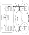
- FIG. 1 is a schematic diagram of a communication system according to each embodiment of the present invention.
- E-UTRA100 is a radio access technology described in Non-Patent Document 3 and the like, and is composed of a cell group (CellCGroup: CG) composed of one or a plurality of frequency bands.
- the eNB (E-UTRAN ⁇ Node ⁇ B) 102 is an E-UTRA base station apparatus.
- EPC (Evolved Packet Core) 104 is a core network described in Non-Patent Document 14 and the like, and is designed as a core network for E-UTRA.
- the interface 112 is an interface between the eNB 102 and the EPC 104, and includes a control plane (Control @ Plane: CP) through which control signals pass and a user plane (User @ Plane: UP) through which the user data passes.
- Control @ Plane: CP Control @ Plane: CP
- User @ Plane: UP user plane
- the NR 106 is a radio access technology described in Non-Patent Document 9 and the like, and includes a cell group (Cell (Group: CG) configured with one or a plurality of frequency bands.
- Cell Group: CG
- gNB g Node B
- the 5GC 110 is a core network described in Non-Patent Document 2 and the like, and is designed as an NR core network, but may be used as an E-UTRA core network having a function of connecting to 5CG.
- E-UTRA may include E-UTRA having a function of connecting to 5CG.
- An interface 114 is an interface between the eNB 102 and the 5GC 110, an interface 116 is an interface between the gNB 108 and the 5GC 110, an interface 118 is an interface between the gNB 108 and the EPC 104, an interface 120 is an interface between the eNB 102 and the gNB 108, and an interface 124 is an EPC 104 and the 5GC 110 Interface between the two.
- the interface 114, the interface 116, the interface 118, the interface 120, and the interface 124 are interfaces that pass only the CP, only the UP, or both the CP and the UP.
- the interface 114, the interface 116, the interface 118, the interface 120, and the interface 124 may not exist depending on the communication system provided by the communication carrier.
- the UE 122 is a terminal device that supports NR or that supports both E-UTRA and NR.
- FIG. 2 is a diagram showing a protocol stack (Protocol @ Stack) of the UP and CP of the terminal device and the base station device in the E-UTRA radio access layer in each embodiment of the present invention.
- Protocol stack Protocol @ Stack
- FIG. 2A is a UP protocol stack diagram used when the UE 122 communicates with the eNB 102.
- PHY (Physical @ layer) 200 is a wireless physical layer (wireless physical layer), and provides a transmission service to an upper layer (upper layer) using a physical channel (Physical @ Channel).
- the PHY 200 is connected to a higher-order MAC (Medium Access Control layer) 202 described later via a transport channel (Transport Channel). Data moves between the MAC 202 and the PHY 200 via the transport channel. Data transmission and reception are performed between the PHY of the UE 122 and the PHY of the eNB 102 via the radio physical channel.
- MAC Medium Access Control layer
- the $ MAC 202 is a medium access control layer that maps various logical channels (Logical @ Channel) to various transport channels.
- the MAC 202 is connected to a higher-order RLC (Radio Link Control layer) 204 described later by a logical channel.
- Logical channels are roughly classified according to the type of information to be transmitted, and are divided into control channels for transmitting control information and traffic channels for transmitting user information.
- the MAC 202 has a function of controlling the PHY 200 to perform intermittent transmission (DRX / DTX), a function of executing a random access (Random @ Access) procedure, a function of notifying transmission power information, a function of performing HARQ control, and the like. (Non-Patent Document 7).
- the RLC 204 divides (segments) data received from a higher-order PDCP (Packet Data Convergence Protocol Protocol) 206 described later, and adjusts the data size so that the lower layer (lower layer) can appropriately transmit data.
- PDCP Packet Data Convergence Protocol Protocol
- Wireless link control layer wireless link control layer.
- the RLC 200 also has a function to guarantee the QoS (Quality of service) required by each data. That is, the RLC 204 has functions such as data retransmission control (Non-Patent Document 6).
- $ PDCP 206 is a packet data convergence protocol layer (packet data convergence protocol layer) for efficiently transmitting an IP packet (IP @ Packet) as user data in a wireless section.
- the PDCP 206 may have a header compression function for compressing unnecessary control information.
- the PDCP 206 may also have a data encryption function (Non-Patent Document 5).
- the data processed in the MAC 202, the RLC 204, and the PDCP 206 are referred to as a MAC PDU (Protocol Data Unit), an RLC PDU, and a PDCP PDU, respectively.
- Data passed from the upper layer to the MAC 202, RLC 204, and PDCP 206 or data passed to the upper layer is called MAC @ SDU (Service @ Data @ Unit), RLC @ SDU, and PDCP @ SDU, respectively.
- FIG. 2B is a protocol stack diagram of a CP used when the UE 122 communicates with the eNB 102.
- the $ CP protocol stack includes an RRC (Radio Resource Control layer) 208 in addition to the PHY 200, the MAC 202, the RLC 204, and the PDCP 206.
- the RRC 208 is a radio link control layer (radio link control layer) that performs setting and resetting of a radio bearer (Radio Bearer: RB) and controls a logical channel, a transport channel, and a physical channel.
- the RB may be divided into a signaling radio bearer (Signaling Radio Bearer: SRB) and a data radio bearer (Data Radio Radio Bearer: DRB), and the SRB is used as a path for transmitting an RRC message that is control information. You may. DRB may be used as a route for transmitting user data.
- Each RB may be set between the eNB 102 and the RRC 208 of the UE 122 (Non-Patent Document 4).
- the above-described function classification of the MAC 202, the RLC 204, the PDCP 206, and the RRC 208 is an example, and some or all of the functions may not be implemented. In addition, some or all of the functions of each layer may be included in another layer.
- the IP layer, the Transmission Control Protocol (TCP) layer above the IP layer, the User Datagram Protocol (UDP) layer, the application layer, and the like are layers higher than the PDCP layer (not shown).
- An RRC layer and a NAS (non Access String) layer are also upper layers of the SDAP layer (not shown).
- the PDCP layer is an RRC layer, a NAS layer, an IP layer, a TCP (Transmission Control Protocol) layer above the IP layer, a UDP (User Datagram Protocol) layer, and a lower layer of an application layer.
- FIG. 3 is a diagram illustrating a protocol stack (Protocol @ Stack) of UP and CP of the terminal device and the base station device in the NR radio access layer in each embodiment of the present invention.
- Protocol stack Protocol @ Stack
- FIG. 3A is a UP protocol stack diagram used when the UE 122 communicates with the gNB 108.
- PHY (Physical @ layer) 300 is a wireless physical layer (wireless physical layer) of NR, and may provide a transmission service to an upper layer using a physical channel (Physical @ Channel).
- the PHY 300 may be connected to a higher-order MAC (Medium Access Control layer) 302 described later via a transport channel (Transport Channel). Data may move between MAC 302 and PHY 300 via a transport channel. Data transmission and reception may be performed between the UE 122 and the PHY of the gNB 108 via the radio physical channel.
- the $ MAC 302 is a medium access control layer that maps various logical channels (Logical @ Channel) to various transport channels.
- the MAC 302 may be connected to a higher-level RLC (Radio Link Control layer) 304 described later by a logical channel.
- Logical channels are largely classified according to the type of information to be transmitted, and may be divided into control channels for transmitting control information and traffic channels for transmitting user information.
- the MAC 302 has a function of controlling the PHY 300 to perform intermittent transmission (DRX / DTX), a function of executing a random access (Random @ Access) procedure, a function of notifying transmission power information, a function of performing HARQ control, and the like. You may have it (Non-Patent Document 13).
- the RLC 304 divides (segments) data received from a higher-order PDCP (Packet Data Convergence Protocol Protocol) 206 described later, and adjusts the data size so that the lower layer can appropriately transmit the data.
- Layer radio link control layer
- the RLC 304 may have a function for guaranteeing the QoS (Quality of service) required by each data. That is, the RLC 304 may have a function such as data retransmission control (Non-Patent Document 12).
- the $ PDCP 306 is a packet data convergence protocol layer (packet data convergence protocol layer) for efficiently transmitting an IP packet (IP @ Packet) as user data in a wireless section.
- the PDCP 306 may have a header compression function for compressing unnecessary control information.
- the PDCP 306 may also have a data encryption function (Non-Patent Document 11).
- An SDAP (Service Data Adaptation Protocol) 310 associates a downlink QoS flow sent from a core network to a terminal device via a base station device with a DRB (mapping), and transmits the downlink QoS flow from the terminal device to the base station device.
- a service data adaptation protocol layer (service data adaptation protocol layer) having a function of mapping an uplink QoS flow sent to a core network to a DRB and storing mapping rule information (Non-Patent Document 16) ).
- the terminal device receives the SDAP @ SDU together with the QoS flow information from the upper layer, the terminal device allocates the SDAP @ SDU to the corresponding DRB based on the stored mapping rule between the QoS flow and the DRB.
- the SDAP @ SDU may be assigned to the default radio bearer (default DRB).
- a QoS flow is composed of one or more service data flows (Service ⁇ Data ⁇ Flow: SDF) that are processed according to the same QoS policy (Non-Patent Document 2).
- the SDAP may have a reflective QoS (Reflective QoS) function of mapping the uplink QoS flow and the DRB based on the information of the downlink QoS flow.
- the end marker PDU is an SDAP control PDU described in Non-Patent Document 16, in which the SDAP entity of the UE determines the QoS flow corresponding to the QoS flow identifier included in the QoS flow identifier field of the end marker PDU, and the end marker PDU. Is used to notify that the mapping with the transmitted radio bearer is finished.
- the IP layer, the Transmission Control Protocol (TCP) layer above the IP layer, the User Datagram Protocol (UDP) layer, and the application layer are upper layers of the SDAP layer (not shown).
- An RRC layer and a NAS (non Access String) layer are also upper layers of the SDAP layer (not shown).
- association between the service data flow and the QoS flow is performed.
- the SDAP layer is an RRC layer, a NAS layer, an IP layer, a TCP (Transmission Control Protocol) layer above the IP layer, a UDP (User Datagram Protocol) layer, and a lower layer of the application layer.
- the data processed in the MAC 302, the RLC 304, the PDCP 306, and the SDAP 310 may be referred to as a MAC PDU (Protocol Data Unit), an RLC PDU, a PDCP PDU, and a SDAP PDU, respectively.
- MAC PDU Protocol Data Unit
- RLC PDU Radio Link Control
- PDCP PDU Packet Control Protocol
- SDAP PDU Secure Access Protocol
- the data passed from the upper layer to the MAC 202, the RLC 204, and the PDCP 206 or the data passed to the upper layer may be called MAC @ SDU (Service @ Data @ Unit), RLC @ SDU, PDCP @ SDU, and SDAP @ SDU, respectively.
- FIG. 3B is a protocol stack diagram of the CP used when the UE 122 communicates with the gNB 108.
- the $ CP protocol stack includes an RRC (Radio Resource Control layer) 308 in addition to the PHY 300, the MAC 302, the RLC 304, and the PDCP 306.
- the RRC 308 is a radio link control layer (radio link control layer) that performs setting and resetting of a radio bearer (Radio Bearer: RB) and controls a logical channel, a transport channel, and a physical channel.
- the RB may be divided into a signaling radio bearer (Signaling Radio Bearer: SRB) and a data radio bearer (Data Radio Radio Bearer: DRB), and the SRB is used as a path for transmitting an RRC message that is control information. You may.
- DRB may be used as a route for transmitting user data.
- Each RB may be set between the gNB 108 and the RRC 308 of the UE 122. Further, a portion of the RB configured by the RLC 304 and the MAC 302 may be called an RLC bearer (Non-Patent Document 10).
- each layer may be included in another layer (layer).
- the MAC 202, the RLC 204, the PDCP 206, and the RRC 208 are respectively referred to as an E-UTRA MAC or an LTE MAC, an E-UTRA RLC or LTE RLC, PDCP for E-UTRA or PDCP for LTE, and RRC for E-UTRA or RRC for LTE.
- the MAC 302, the RLC 304, the PDCP 306, and the RRC 308 may be referred to as an NR MAC, an NR RLC, an NR RLC, and an NR RRC, respectively.
- the space may be described using a space such as E-UTRA @ PDCP, LTE @ PDCP, or NR @ PDCP.
- the eNB 102, the gNB 108, the EPC 104, and the 5GC 110 may be connected via an interface 112, an interface 116, an interface 118, an interface 120, and an interface 114. Therefore, in order to support various communication systems, the RRC 208 of FIG. 2 may be replaced with the RRC 308 of FIG. Further, the PDCP 206 in FIG. 2 may be replaced with the PDCP 306 in FIG. Further, the RRC 308 in FIG. 3 may include the function of the RRC 208 in FIG. Further, the PDCP 306 in FIG. 3 may be the PDCP 206 in FIG.
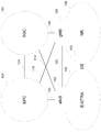
- FIG. 4 shows an example of a 3GPP VoIP network configuration.
- the network shown in FIG. 4 includes an IMS network 426, an IP core network 424 of the operator, base stations 404 and 406, and wireless access networks (wireless access networks) 420 and 422 configured under the base stations.
- terminals (UE: User @ Equipment) 400 and 402 wirelessly connect to base stations 404 and 406 via wireless access networks 420 and 422, respectively, and connect to an IP core network 424 via the base stations 404 and 406.
- the base stations 404 and 406 may be the eNB 102 or the gNB 108.
- the IP core network 424 may be the EPC 104 or the 5GC 110.
- the UEs 400 and 402 may be the UE 122.
- the radio access networks 420 and 422 may be the E-UTRA 100 or the NR 106.
- the IMS network is a network for performing information management for call control and routing of signaling messages (SIP: Session Initiation Protocol) for call control and interconnection with legacy networks of 3GPP and networks other than 3GPP.
- SIP Session Initiation Protocol
- P-CSCFs Proxy Call Session Control Function
- P-CSCFs Proxy Call Session Control Function
- the UE searches for a P-CSCF to which it can connect, and transmits an IMS signaling message to this P-CSCF.
- S-CSCFs (Serving CSCFs) 410 and 414 are CSCFs that manage contact information and manage sessions of UEs.
- the S-CSCFs 410 and 414 download necessary information from an HSS (Home ⁇ Subscriber ⁇ Server) 418 when managing the contact information of the UE.
- HSS Home ⁇ Subscriber ⁇ Server
- the $ I-CSCF (Interrogating $ CSCF) 412 holds CSCF information between management domains (units of a network managed by each operator).
- the IMS signaling message is transferred via the I-CSCF 412 when the P-CSCF and the S-CSCF do not have the next node information to transfer the IMS signaling message.
- the I-CSCF 412 may confirm the information of the message transfer destination CSCF by referring to the HSS 418 for information. For example, a case where a SIP @ INVITE message is sent will be described.
- the SIP @ INVITE message is first sent from the calling UE to the P-CSCF of the domain where the UE is located (the calling domain) via the IP core network, and is sent from the P-CSCF to the calling S-CSCF. Is forwarded to The SIP @ INVITE message is forwarded to the S-CFCS in the called domain after appropriate processing is performed in the calling S-CSCF. At this time, the SIP @ INVITE message may pass through the I-CSCF 112 in some cases. The called S-CSCF transfers the received SIP @ INVITE message to the called UE via the P-CSCF.
- the operator's IP core network 424 shown in FIG. 4 performs routing of communication data, QoS (Quality of Service) control, management of terminal location information, and the like.
- QoS Quality of Service
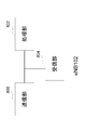
- FIG. 5 is a flowchart showing an example of a procedure until a VoIP call using the 3GPP IMS is performed.
- FIG. 5 shows a flow example when making a call from UE 400 to UE 402.
- a SIP @ INVITE message is transmitted from UE 400 to UE 402 via an IMS network (step S500)
- a SIP @ 183 ⁇ Session ⁇ Progress message is transmitted from UE 402 to UE 400 via an IMS network (step S502).
- the SIP INVITE message and the SIP 183 Session Progress message are exchanged between the UEs, and negotiations regarding communication, for example, negotiations on a codec to be used and a codec mode and a bit rate are performed.
- the SDP (Session Description Protocol) added to the SIP INVITE message includes a mechanism used in the VoIP communication, such as a codec method, a codec mode (bit rate and processing delay, etc.), and a protocol (RTP (Real-time). (Transport @ Protocol) Type of payload format) is described.
- the UE 402 selects one mechanism from a plurality of candidates described in the SDP offer and describes the mechanism in the SDP answer.
- the UE 402 adds the SDP answer to the SIP ⁇ 183 ⁇ Session ⁇ Progress message in step S502 and sends the message to the UE 400.
- the IMS message is not processed by the base station. That is, the base station does not store the contents of the IMS message. Therefore, in order for the base station to determine the SRVCC threshold value in consideration of the packet loss robustness characteristics of the negotiated codec, the negotiated codec and information such as the mode and bit rate used are needed. Information needs to be provided from the UE.
- the packet loss rate and / or allowable packet loss rate in each embodiment of the present invention is the maximum packet loss rate described in Non-Patent Document 19, that is, the maximum end-to-end packet loss in a VoIP call. It may be rate.
- the packet loss rate and / or the allowable packet loss rate in each embodiment of the present invention refers to a packet error loss rate occurring in a wireless interface between a terminal and a base station (see Non-Patent Document 20). (Packet Error Loss Rate: PELR).
- PELR Packet Error Loss Rate
- the packet loss rate and / or the allowable packet loss rate in each embodiment of the present invention may be expressed using other terms such as robustness.
- Embodiment 1 of the present invention will be described with reference to FIGS.
- FIG. 6 is a diagram showing an example of a flow of a UE capability procedure and an RRC connection reconfiguration procedure in each embodiment of the present invention.
- the RRC connection reset procedure may be an RRC reset procedure.
- the UE capability procedure is a means used to transfer the radio access capability information of the UE 122 from the UE 122 to the network in LTE and / or NR.
- the RRC connection reset procedure (RRC Connection Reconfiguration) is described in Non-Patent Document 4, which establishes, changes, and releases RBs in LTE (E-UTRA), and changes and releases secondary cells, and also performs handover. And a procedure used for Measurement and the like.
- the RRC re-establishment procedure (RRC Connection Reconfiguration) performs establishment, change, and release of RB in NR, and change, release, and the like of a secondary cell described in Non-Patent Document 10, and also performs handover (including synchronization). This is a procedure used for resetting, measurement, and the like.
- the RRC connection re-establishment procedure is performed in MR-DC, especially when the core network is the EPC 104 and the master node is the eNB 102, that is, the EN-DC (E-UTRA-NR @ Dual @ Connectivity) and the core network.
- NGEN-DC NG-RAN @ E-UTRA-NR @ Dual @ Connectivity
- eNB102 also referred to as extended eNB102
- extended eNB102 is a core network
- the RRC connection re-establishment procedure includes not only LTE but also establishment, change, and release of RB in NR and change, release, etc.
- the eNB 102 sends a UE capability inquiry (UECapabilityEnquiry) message to the UE 122 to inquire the UE 122 of the UE capability (UE @ Capability) (step S600).
- the UE 122 creates a UE capability information (UECapabilityInformation) message based on the UE capability inquiry received from the eNB 102, and transmits the message to the eNB 102 (Step S602).
- messages such as the UE capability inquiry message and the UE capability information message may have other names.
- the eNB 102 creates an RRC connection reconfiguration message (RRCConnectionReconfiguration) based on the UE capability information acquired in the UE capability procedure, and transmits the message to the UE 122 (step S604).
- the UE 122 performs various settings, for example, a setting of a prohibition timer, a setting of a transmission cycle timer, and the like, according to information elements described later included in the RRC connection reconfiguration message.
- the UE 122 may send an RRC connection reconfiguration completion message (RRCConnectionReconfigurationComplete) or the like to the eNB 102 (not shown).
- the RRC reconfiguration message may be rephrased as RRC reconfiguration
- the RRC reconfiguration complete message may be rephrased as RRC reconfiguration complete.
- FIG. 7 is a block diagram showing a configuration of a terminal device (UE 122) according to each embodiment of the present invention.
- UE 122 terminal device
- FIG. 7 shows only main components closely related to the present invention.
- the UE 122 shown in FIG. 7 receives, from the eNB 102, a message such as a UE capability inquiry message and an RRC connection reconfiguration message, a MAC control element (MAC Control Element: MAC CE), a notification from an upper layer, and the like, and A processing unit 702 that performs processing according to various information elements (IE: Information @ Element) included in the received message, various conditions such as fields, a notification from an upper layer, a message such as a UE capability information message to the eNB 102, and a MAC control element. (MAC ⁇ Control ⁇ Element: MAC @ CE), and a transmission unit 704 for transmitting a notification to an upper layer and the like. Further, a control unit for controlling the operation of each unit based on various conditions may be separately provided.
- IE Information @ Element
- FIG. 8 is a block diagram showing a configuration of the base station apparatus (eNB 102) according to each embodiment of the present invention. In order to avoid a complicated description, FIG. 8 shows only main components closely related to the present invention.
- the eNB 102 illustrated in FIG. 8 transmits a message such as a UE capability inquiry message and an RRC connection reconfiguration message to the UE 122, a transmission unit 800 that transmits a MAC control element (MAC Control Element: MAC CE), and various information elements (IEs).
- MAC Control Element MAC CE
- IEs information elements
- the configuration shown in FIG. 8 may be applied to gNB108.
- the message transmitted from transmitting section 800 to UE 122 may be an RRC reconfiguration message.
- a control unit for controlling the operation of each unit based on various conditions may be separately provided.
- FIG. 9 is a diagram showing an ASN. Representing an information element included in the UE capability information message in FIG. It is an example of one description.
- specifications related to RRC include messages related to RRC and information elements (Information Element (IE)) in ASN. This is described using 1.
- the message and / or information element related to the RRC includes one or more fields and a value of the field (Value). Field values can take other information elements besides integers, byte strings, lists, and the like.
- the description may be made by replacing the “field” with the “information element”.
- the ASN In the example of ⁇ 1>, ⁇ abbreviation> and ⁇ omission> are ASN.
- ASN. 1 is ASN. It does not follow the one notation method correctly, but is an example of RRC reset parameters in the present invention, and other names or other notations may be used. Also, the ASN. The first example shows only an example relating to main information closely related to the present invention in order to avoid a complicated description. Note that, unless otherwise explicitly described, other ASN. The above description also applies to one description.
- the information element represented by UE-CapabilityRAT-ContainerList included in the capability information message has a list of containers represented by UE-CapabilityRAT-Container of the information element as a value (Value), and the UE capability is RAT. Each container may be included in one container.
- the UE-CapabilityRAT-Container includes a rat-Type field having information indicating a type (Type) of a radio access technology (Radio Access Technology: RAT) as a value, and a byte sequence indicating a UE capability of the RAT indicated by rat-Type.
- a ueCapabilityRAT-Container field having a value may be included.
- the value of the ueCapabilityRAT-Container field may include a UE-EUTRA-Capability information element. Also, when the value of rat-Type of UE-CapabilityRAT-Container is associated with NR, the value of the ueCapabilityRAT-Container field includes an information element for NR, for example, a UE-NR-Capability information element. You may.
- the MMTEL-Parameters information element may have the MMTEL-Parameters information element as a value.
- the MMTEL-Parameters information element may include an auxiliary function for VoIP using the IMS of the UE 122, for example, whether to support delay budget (delay @ budget) reporting, whether to support recommended bit rate reception, and the like.
- the MMTEL-Parameters information element may include a field (packetLossRateReporting) indicating that the UE 122 supports the packet loss rate report, as shown in FIG.
- packetLossRateReporting indicates that the packet loss rate report is not supported.
- the packet loss rate report may be that the UE 122 reports an allowable packet loss rate to the eNB 102 based on an instruction or information from an upper layer.
- FIG. 10 shows ASN.1 representing the information element included in the RRC connection reconfiguration message in FIG. 6 according to Embodiment 1 of the present invention. It is an example of one description.
- an information element represented by RRCConnectionReconfiguration-IEs which is an information element of RRC connection reconfiguration, is an information element relating to measurement, an information element relating to radio resource setting, and the like, and an OtherConfig information element relating to other settings. It may include the indicated information element.
- the information element indicated by OtherConfig may include a field indicated by packetLossRateReportingConfig, which is a field indicating the setting for the above-described packet loss rate report.
- the field indicated by packetLossRateReportingConfig may have a structure in which a field indicated by release indicating release and a field indicated by setup indicating setting are selected (CHOICE).
- a field for setting a packet loss rate report prohibition timer which is a timer for prohibiting the above-described packet loss rate report for a certain period, is indicated by a packetLossRateProhibitTimer (packet loss rate report prohibition timer).
- Field the value of the field indicated by packetLossRateProhibitTimer may be enumerated (ENUMERATED) as the value of the packet loss rate report prohibition timer.
- the field indicated by packetLossRateProhibitTimer is included in the OtherConfig information element as an example, and may be included in another information element such as an information element indicating a logical channel setting in MAC, for example.
- the information element indicating the setting of the logical channel may further include a field indicating the priority of the logical channel, an identifier of the logical channel group, or a field indicating the association.
- the processing unit 802 of the eNB 102 creates a UE capability inquiry message including a field indicating a packet loss rate report to cause the UE 122 to perform processing, and transmits the message to the UE 122 from the transmission unit 800 (not shown).
- the receiving unit 700 of the UE 122 receives the UE capability inquiry message from the eNB 102. If the processing unit 702 of the UE 122 supports the packet loss rate report, the processing unit 702 performs a process of creating a UE capability information message including a field indicating the packet loss rate report, and transmits the message from the transmission unit 704 (step S1100).
- the receiving unit 804 of the eNB 102 receives a UE capability information message from the UE 112 (not shown).
- the processing unit 802 of the eNB 102 creates an RRC connection reset message including a field indicating a setting for a packet loss rate report for causing the UE 122 to perform processing, and transmits the message to the UE 122 from the transmitting unit 800 (not shown). .
- the receiving unit 700 of the UE 122 receives the RRC connection reset message from the eNB 102.
- the processing unit 702 of the UE 122 may perform a process of setting a packet loss rate report based on a field indicating a setting for the packet loss rate report included in the RRC connection reconfiguration message received from the eNB 102 (Step 1102).
- the process of setting the packet loss rate report is, for example, if the field indicated by packetLossRateReportingConfig is set (setup), it is determined that transmission of the packet loss rate report is set, and the field indicated by packetLossRateReportingConfig is other than that. For example, it may be determined that the packet loss rate report is not transmitted if the packet is released, and if the packet loss rate report prohibition timer is running, the timer may be stopped. Further, based on the determination that the transmission of the packet loss rate report is set, the upper layer may be notified that the packet loss rate report is to be performed.
- the processing unit 702 of the UE 122 creates a packet loss rate report in accordance with the content of the notification received from the upper layer, and transmits the report to the eNB 102 (step 1104).
- the above-described creation of the packet loss rate report content and transmission to the eNB 102 may be performed based on the determination that transmission of the packet loss rate report has been set in step S1102. Further, the above-described transmission to the eNB 102 or the creation of the above-described packet loss rate report content and the transmission to the eNB 102 may be performed based on the fact that the packet loss rate report prohibition timer is not operating.
- the packet loss rate report prohibition timer may be started or restarted according to the value of the packet loss rate report prohibition timer.
- the notification regarding the packet loss rate received from the upper layer described above may include both the allowable packet loss rate in the uplink direction and the allowable packet loss rate in the downlink direction. Either the allowable packet loss rate in the downlink direction or the allowable packet loss rate in the downlink direction may be included. Further, the notification regarding the packet loss rate received from the upper layer described above may include other information.
- the upper layer may calculate and determine the allowable packet loss rates in the uplink and downlink directions from the codec in use, the codec mode and bit rate, the state of the jitter buffer, and the like.
- the above-described packet loss rate report content may include both the allowable packet loss rate in the uplink direction and the allowable packet loss rate in the downlink direction, or the allowable packet loss rate in the uplink direction. Or the allowable packet loss rate in the downlink direction may be included. Further, the packet loss rate report content described above may include other information.
- the process of receiving the notification of the packet loss rate received from the upper layer and transmitting the packet loss rate report content to the eNB may be performed in the RRC layer or the MAC layer.
- the above-described packet loss rate report content may be transmitted using an RRC message.
- the above-described packet loss rate report content may be transmitted using a MAC control element (MAC @ CE).
- FIG. 12 is an example of a packet loss rate report information element in a packet loss rate report format when transmitting the packet loss rate report content to the eNB using an RRC message in each embodiment of the present invention.
- the packet loss rate report information element may include a field indicated by dl-packetLossRate indicating the packet loss rate in the downlink direction, or may indicate the packet loss rate in the uplink direction.
- a field indicated by ul-packetLossRate may be included. In the field indicated by dl-packetLossRate and the field indicated by ul-packetLossRate, the value of the packet loss rate may be listed (ENUMERATED).
- Plr1, plr2, plr2dot7, and plr4dot5 which are examples of the enumerated packet loss rates shown in FIG. 12, are a packet loss rate of 1%, a packet loss rate of 2%, a packet loss rate of 2.7%, and a packet loss rate, respectively. 4.5 percent.
- a default value of the packet loss rate may be specified. In the example of FIG. 11, 1% indicated by plr1 is specified as the default value of the packet loss rate.
- the packet loss rate report information element may be included in a UE Assistance Information (UE Assistance Information) message described in Non-Patent Document 4, or may be included in a UE information (UE @ Information) procedure described in Non-Patent Document 4. May be included in the UE information response (UEInformationResponse) message, or may be included in another message.
- UE Assistance Information UE Assistance Information
- UE @ Information UE information
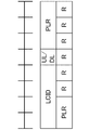
- FIG. 13 is an example of a packet loss rate report MAC @ CE in a packet loss rate report format when transmitting the packet loss rate report content to the eNB by MAC @ CE in each embodiment of the present invention.
- the field represented by the LCID in FIG. 13 is a logical channel identifier field, and may mean an identifier of a logical channel for which a packet loss rate report is performed.
- the identifier of the logical channel for reporting the packet loss rate may be set in a logical channel identifier table for an uplink shared channel (UL-SCH: Uplink Shared Channel) described in Non-Patent Document 7.
- UL-SCH Uplink Shared Channel
- the field indicated by UL / DL may indicate whether the packet loss rate report is a report on the uplink or a report on the downlink. For example, when “0" is set, a report on the uplink may be made, and when "1" is set, a report on the downlink may be made.
- the field indicated by $ PLR may be a field indicating a packet loss rate (Packet Loss Rate).
- FIG. 14 shows an example of a table of values for the packet loss rate in each embodiment of the present invention.
- the table of values for the packet loss rate includes a list of packet loss rates (percent) and an index for each packet loss rate.
- the field indicated by the PLR in FIG. 13 may include the index described in the example of FIG.
- the field indicated by 'R' is a field indicating reservation (Reserve), and '0' may be set.
- each field shown in FIG. 13 may not be as shown in FIG. Some of the fields shown in FIG. 13 may not be present, or another field may be present. Also, the index and the packet loss rate shown in FIG. 14 are examples, and need not be the same.
- an example of a processing method when the packet loss rate report content is transmitted to the eNB by MAC @ CE may be as follows. That is, when the MAC entity receives the notification regarding the packet loss rate from the upper layer for the designated logical channel, the MAC entity performs the direction (uplink, downlink, or uplink) included in the notification regarding the packet loss rate. And downlink), based on the fact that the specified logical channel has not been triggered, the packet loss rate report is generated for the specified logical channel, direction, and packet loss rate. Trigger.
- the above MAC @ CE is assigned to the specified logical channel, direction, and packet loss rate. Create a packet loss rate report. Note that the above-described MAC @ CE creation processing may be performed based on the fact that the packet loss rate report prohibition timer is not running, or the packet loss rate report prohibition timer may be set before canceling the packet loss rate report. You may start.
- Embodiment 1 of the present invention when the UE receives the notification of the packet loss rate from the upper layer, the UE notifies the eNB of the packet loss rate, so that the packet loss rate that the upper layer of the UE can tolerate in the eNB. Can be determined in consideration of SRVCC handover and the like. That is, the terminal device can efficiently perform communication by suppressing deterioration of the communication quality.
- Embodiment 2 of the present invention will be described with reference to FIGS. 1 to 9, FIGS. 12 to 14, and FIGS. FIGS. 1 to 9 and FIGS. 12 to 14 are the same as the first embodiment, but will be described again in the second embodiment.
- FIG. 6 is a diagram showing an example of a flow of a UE capability procedure and an RRC connection reconfiguration procedure in each embodiment of the present invention.
- the RRC connection reset procedure may be an RRC reset procedure.
- the UE capability procedure is a means used to transfer the radio access capability information of the UE 122 from the UE 122 to the network in LTE and / or NR.
- the RRC connection reset procedure (RRC Connection Reconfiguration) is described in Non-Patent Document 4, which establishes, changes, and releases RBs in LTE (E-UTRA), and changes and releases secondary cells, and also performs handover. And a procedure used for Measurement and the like.
- the RRC re-establishment procedure (RRC Connection Reconfiguration) performs establishment, change, and release of RB in NR, and change, release, and the like of a secondary cell described in Non-Patent Document 10, and also performs handover (including synchronization). This is a procedure used for resetting, measurement, and the like.
- the RRC connection re-establishment procedure is performed in MR-DC, especially when the core network is the EPC 104 and the master node is the eNB 102, that is, the EN-DC (E-UTRA-NR @ Dual @ Connectivity) and the core network.
- NGEN-DC NG-RAN @ E-UTRA-NR @ Dual @ Connectivity
- eNB102 also referred to as extended eNB102
- extended eNB102 is a core network
- the RRC connection re-establishment procedure includes not only LTE but also establishment, change, and release of RB in NR and change, release, etc.
- the eNB 102 sends a UE capability inquiry (UECapabilityEnquiry) message to the UE 122 to inquire the UE 122 of the UE capability (UE @ Capability) (step S600).
- the UE 122 creates a UE capability information (UECapabilityInformation) message based on the UE capability inquiry received from the eNB 102, and transmits the message to the eNB 102 (Step S602).
- messages such as the UE capability inquiry message and the UE capability information message may have other names.
- the eNB 102 creates an RRC connection reconfiguration message (RRCConnectionReconfiguration) based on the UE capability information acquired in the UE capability procedure, and transmits the message to the UE 122 (step S604).
- the UE 122 performs various settings, for example, a setting of a prohibition timer, a setting of a transmission cycle timer, and the like, according to information elements described later included in the RRC connection reconfiguration message.
- the UE 122 may send an RRC connection reconfiguration completion message (RRCConnectionReconfigurationComplete) or the like to the eNB 102 (not shown).
- the RRC reconfiguration message may be rephrased as RRC reconfiguration
- the RRC reconfiguration complete message may be rephrased as RRC reconfiguration complete.
- FIG. 7 is a block diagram showing a configuration of a terminal device (UE 122) according to each embodiment of the present invention.
- UE 122 terminal device
- FIG. 7 shows only main components closely related to the present invention.
- the UE 122 shown in FIG. 7 receives, from the eNB 102, a message such as a UE capability inquiry message and an RRC connection reconfiguration message, a MAC control element (MAC Control Element: MAC CE), a notification from an upper layer, and the like, and A processing unit 702 that performs processing according to various information elements (IE: Information @ Element) included in the received message, various conditions such as fields, a notification from an upper layer, a message such as a UE capability information message to the eNB 102, and a MAC control element. (MAC ⁇ Control ⁇ Element: MAC @ CE), and a transmission unit 704 for transmitting a notification to an upper layer and the like. Further, a control unit for controlling the operation of each unit based on various conditions may be separately provided.
- IE Information @ Element
- FIG. 8 is a block diagram showing a configuration of the base station apparatus (eNB 102) according to each embodiment of the present invention. Note that FIG. 8 illustrates only main components which are closely related to one embodiment of the present invention to avoid complicated description.
- the eNB 102 illustrated in FIG. 8 transmits a message such as a UE capability inquiry message and an RRC connection reconfiguration message to the UE 122, a transmission unit 800 that transmits a MAC control element (MAC Control Element: MAC CE), and various information elements (IEs).
- MAC Control Element MAC CE
- IEs information elements
- the configuration shown in FIG. 8 may be applied to gNB108.
- the message transmitted from transmitting section 800 to UE 122 may be an RRC reconfiguration message.
- a control unit for controlling the operation of each unit based on various conditions may be separately provided.
- FIG. 9 is a diagram showing an ASN. Representing an information element included in the UE capability information message in FIG. It is an example of one description.
- specifications related to RRC include messages related to RRC and information elements (Information Element (IE)) in ASN. This is described using 1.
- the message and / or information element related to the RRC includes one or more fields and a value of the field (Value). Field values can take other information elements besides integers, byte strings, lists, and the like.
- the description may be made by replacing the “field” with the “information element”.
- the ASN In the example of ⁇ 1>, ⁇ abbreviation> and ⁇ omission> are ASN.
- ASN. 1 is ASN. It does not follow the one notation method correctly, but is an example of RRC reset parameters in the present invention, and other names or other notations may be used. Also, the ASN. The example 1 shows only an example related to main information which is closely related to one embodiment of the present invention in order to avoid a complicated description. Note that, unless otherwise explicitly described, other ASN. The above description also applies to one description.
- the information element represented by UE-CapabilityRAT-ContainerList included in the capability information message has a list of containers represented by UE-CapabilityRAT-Container of the information element as a value (Value), and the UE capability is RAT. Each container may be included in one container.
- the UE-CapabilityRAT-Container includes a rat-Type field having information indicating a type (Type) of a radio access technology (Radio Access Technology: RAT) as a value, and a byte sequence indicating a UE capability of the RAT indicated by rat-Type.
- a ueCapabilityRAT-Container field having a value may be included.
- the value of the ueCapabilityRAT-Container field may include a UE-EUTRA-Capability information element. Also, when the value of rat-Type of UE-CapabilityRAT-Container is associated with NR, the value of the ueCapabilityRAT-Container field includes an information element for NR, for example, a UE-NR-Capability information element. You may.
- the MMTEL-Parameters information element may have the MMTEL-Parameters information element as a value.
- the MMTEL-Parameters information element may include an auxiliary function for VoIP using the IMS of the UE 122, for example, whether to support delay budget (delay @ budget) reporting, whether to support recommended bit rate reception, and the like.
- the MMTEL-Parameters information element may include a field (packetLossRateReporting) indicating that the UE 122 supports the packet loss rate report, as shown in FIG.
- packetLossRateReporting indicates that the packet loss rate report is not supported.
- the packet loss rate report may be that the UE 122 reports an allowable packet loss rate to the eNB 102 based on an instruction or information from an upper layer.
- the packetLossRateReporting field is included in the MMTEL-Parameters information element as an example, and may be included in another information element.
- FIG. 15 is a diagram illustrating an ASN.3 representing an information element included in the RRC connection reconfiguration message in FIG. 6 according to the second embodiment of the present invention. It is an example of one description.
- an information element represented by RRCConnectionReconfiguration-IEs which is an information element of RRC connection reconfiguration, is an information element relating to measurement, an information element relating to radio resource setting, and the like, and an OtherConfig which is an information element relating to other settings. It may include the indicated information element.
- the information element indicated by OtherConfig may include a field indicated by packetLossRateReportingConfig, which is a field indicating the setting for the above-described packet loss rate report.
- the field indicated by packetLossRateReportingConfig may have a structure in which a field indicated by release indicating release and a field indicated by setup indicating setting are selected (CHOICE).
- the field indicated by setup has a packet loss rate report period timer, which is a field related to the setting of a packet loss rate report period timer, which is a period for transmitting the above described packet loss rate report, and a field (packet loss rate report period timer field) indicated by packetLossRatePeriodicTimer.
- the value of the field indicated by packetLossRatePeriodicTimer may be enumerated (ENUMERATED) as the value of the packet loss rate report cycle timer.
- the packet loss rate report cycle timer is not divided for uplink and downlink, but the packet loss rate report cycle timer is divided into an uplink field and a downlink field. Is also good.
- the field indicated by packetLossRatePeriodicTimer is included in the OtherConfig information element as an example, and may be included in another information element such as an information element indicating the setting of a logical channel in the MAC.
- the information element indicating the setting of the logical channel may further include a field indicating the priority of the logical channel, an identifier of the logical channel group, or a field indicating the association.
- the processing unit 802 of the eNB 102 creates a UE capability inquiry message including a field indicating a packet loss rate report to cause the UE 122 to perform processing, and transmits the message to the UE 122 from the transmission unit 800 (not shown).
- the receiving unit 700 of the UE 122 receives the UE capability inquiry message from the eNB 102. If the processing unit 702 of the UE 122 supports the packet loss rate report, the processing unit 702 performs a process of creating a UE capability information message including a field indicating the packet loss rate report, and transmits the message from the transmission unit 704 (step S1600).
- the receiving unit 804 of the eNB 102 receives a UE capability information message from the UE 112 (not shown).
- the processing unit 802 of the eNB 102 creates an RRC connection reset message including a field indicating a setting for a packet loss rate report for causing the UE 122 to perform processing, and transmits the message to the UE 122 from the transmitting unit 800 (not shown). .
- the receiving unit 700 of the UE 122 receives the RRC connection reset message from the eNB 102.
- the processing unit 702 of the UE 122 may perform a process of setting a packet loss rate report based on a field indicating a setting for the packet loss rate report included in the RRC connection reconfiguration message received from the eNB 102 (Step 1602).
- the process of setting the packet loss rate report is, for example, if the field indicated by packetLossRateReportingConfig is set (setup), it is determined that transmission of the packet loss rate report is set, and the field indicated by packetLossRateReportingConfig is other than that. For example, if the packet is released, it may be determined that the packet loss rate report is not transmitted, and if the packet loss rate transmission cycle timer is running, the timer may be stopped. If it is determined that the transmission of the above-described packet loss rate report is set, the processing may start a packet loss rate transmission cycle timer. Further, based on the determination that the transmission of the packet loss rate report is set, the upper layer may be notified that the packet loss rate report is to be performed.
- the processing unit 702 of the UE 122 When the packet loss rate transmission cycle timer expires (expire), the processing unit 702 of the UE 122 creates a packet loss rate report content according to the content of the notification received from the upper layer, and transmits the report content to the eNB 102 (step 1604). If the UE 122 has not received a notification about the packet loss rate from the upper layer when the packet loss rate transmission cycle timer has expired, the UE 122 may send a default packet loss rate or may make an inquiry to the upper layer. The above-described creation of the packet loss rate report content and transmission to the eNB 102 may be performed based on the determination that transmission of the packet loss rate report has been set in step S1102.
- a packet loss rate report content is created in accordance with the content of the notification received from the upper layer, and transmitted to the eNB 102.
- the packet loss rate report content may be transmitted according to the content of the notification received from the upper layer when the inquiry (Query) is received from the eNB 102 instead of when the above-described packet loss rate report cycle timer expires. You may.
- the packet loss rate reporting cycle timer may be reset or restarted. If the UE 122 does not receive a notification about the packet loss rate from the upper layer when receiving the Query from the eNB 102, the UE 122 may send a default packet loss rate or may make an inquiry to the upper layer to check the packet loss rate. You may receive a notification. Further, each time a query is received from the eNB 102, an inquiry may be made to the upper layer to receive a notification regarding the packet loss rate.
- the notification regarding the packet loss rate received from the upper layer described above may include both the allowable packet loss rate in the uplink direction and the allowable packet loss rate in the downlink direction. Either the allowable packet loss rate in the downlink direction or the allowable packet loss rate in the downlink direction may be included. Further, the notification regarding the packet loss rate received from the upper layer described above may include other information.
- the upper layer may calculate and determine the allowable packet loss rates in the uplink and downlink directions based on the codec in use, the codec mode and bit rate, the status of the jitter buffer, and the like.
- the above-described packet loss rate report content may include both the allowable packet loss rate in the uplink direction and the allowable packet loss rate in the downlink direction, or the allowable packet loss rate in the uplink direction. Or the allowable packet loss rate in the downlink direction may be included. Further, the packet loss rate report content described above may include other information.
- the above-described process of receiving the notification regarding the packet loss rate received from the upper layer transmitting the packet loss rate report content to the eNB, receiving the above Query from the eNB, and transmitting the packet loss rate report content to the eNB.
- the processing may be performed in the RRC layer “or may be performed in the MAC layer.
- the above-described packet loss rate report content and the query are transmitted and received using the RRC message.
- the above-described packet loss rate report content and the query may be transmitted and received using a MAC control element (MAC @ CE).
- FIG. 12 is an example of a packet loss rate report information element in a packet loss rate report format when transmitting the packet loss rate report content to the eNB using an RRC message in each embodiment of the present invention.
- the packet loss rate report information element may include a field indicated by dl-packetLossRate indicating the packet loss rate in the downlink direction, or may indicate the packet loss rate in the uplink direction.
- a field indicated by ul-packetLossRate may be included. In the field indicated by dl-packetLossRate and the field indicated by ul-packetLossRate, the value of the packet loss rate may be listed (ENUMERATED).
- Plr1, plr2, plr2dot7, and plr4dot5 which are examples of the enumerated packet loss rates shown in FIG. 12, are a packet loss rate of 1%, a packet loss rate of 2%, a packet loss rate of 2.7%, and a packet loss rate, respectively. 4.5 percent.
- a default value of the packet loss rate may be specified. In the example of FIG. 11, 1% indicated by plr1 is specified as the default value of the packet loss rate.
- the packet loss rate report information element may be included in a UE Assistance Information (UE Assistance Information) message described in Non-Patent Document 4, or may be included in a UE information (UE @ Information) procedure described in Non-Patent Document 4. May be included in the UE information response (UEInformationResponse) message, or may be included in another message.
- UE Assistance Information UE Assistance Information
- UE @ Information UE information
- a format similar to the packet loss rate report format shown in FIG. 12 may be applied as a field for querying a packet loss rate report, or another The format may be used as a field for packet loss rate report inquiry.
- the field used for the query may be included in a UE information request (UEInformationRequest) message in a UE information (UE @ Information) procedure described in Non-Patent Document 4, or may be included in another message. Is also good.
- FIG. 13 is an example of a packet loss rate report MAC @ CE in a packet loss rate report format when transmitting the packet loss rate report content to the eNB by MAC @ CE in each embodiment of the present invention.
- the field represented by the LCID in FIG. 13 is a logical channel identifier field, and may mean an identifier of a logical channel for which a packet loss rate report is performed.
- the identifier of the logical channel for reporting the packet loss rate may be set in a logical channel identifier table for an uplink shared channel (UL-SCH: Uplink Shared Channel) described in Non-Patent Document 7.
- UL-SCH Uplink Shared Channel
- the field indicated by UL / DL may indicate whether the packet loss rate report is a report on the uplink or a report on the downlink. For example, when “0" is set, a report on the uplink may be made, and when "1" is set, a report on the downlink may be made.
- the field indicated by $ PLR may be a field indicating a packet loss rate (Packet Loss Rate).
- FIG. 14 shows an example of a table of values for the packet loss rate in each embodiment of the present invention.
- the table of values for the packet loss rate includes a list of packet loss rates (percent) and an index for each packet loss rate.
- the field indicated by the PLR in FIG. 13 may include the index described in the example of FIG.
- the field indicated by 'R' is a field indicating reservation (Reserve), and '0' may be set.
- each field shown in FIG. 13 may not be as shown in FIG. Some of the fields shown in FIG. 13 may not be present, or another field may be present. Also, the index and the packet loss rate shown in FIG. 14 are examples, and need not be the same. Further, an index indicating a default packet loss rate may be included in the index illustrated in FIG.
- the packet loss rate report inquiry format may be the same as the packet loss rate report MAC @ CE shown in FIG. 13 or may be another format. Is also good.
- the identifier of the logical channel for the packet loss rate report inquiry may be set in the logical channel identifier table for the downlink shared channel (DL-SCH: Downlink ⁇ Shared ⁇ Channel) described in Non-Patent Document 7.
- an example of a processing method when the packet loss rate report content is transmitted to the eNB by MAC @ CE may be as follows. That is, when the packet loss rate period timer for the specified logical channel has expired, or when the MAC MAC for Query has been received from the eNB on the specified logical channel, the MAC entity performs the specified direction (uplink or downlink). For the specified logical channel, direction, and packet loss rate, based on the fact that the packet loss rate report for the link or the uplink and the downlink) has not been triggered for the specified logical channel, Trigger a packet loss rate report.
- the above MAC @ CE is assigned to the specified logical channel, direction, and packet loss rate. Create a packet loss rate report.
- the UE periodically notifies the eNB of the packet loss rate, so that the threshold of the SRVCC handover or the like in consideration of the packet loss rate that the upper layer of the UE can allow in the eNB is considered. Can be determined. That is, the terminal device can efficiently perform communication by suppressing deterioration of the communication quality.
- the upper layer when UE capability information related to the packet loss rate report is transmitted to the eNB 102, the upper layer may be notified that the packet loss rate report is to be performed.
- each embodiment of the present invention may be applied to communication between the UE and the gNB. It may be applied to RAT.
- the MAC control element may be a MAC control element PDU (Protocol @ Data @ Unit).
- MAC @ CE may be a part of data transmitted and received between the terminal and the base station in response to an RRC message transmitted and received between the terminal and the base station.
- packet loss rate report prohibition timer in the first embodiment of the present invention and the packet loss rate report cycle timer in the second embodiment of the present invention are used for re-establishing the RRC connection and restarting the RRC connection (Resume). If it was operating at that time, it may be stopped.
- the packet loss rate has been described as a method of notifying the information possessed by the upper layer from the terminal device to the base station by receiving the notification from the upper layer. May be applied to a delay budget report (delay @ budget @ reporting) described in Non-Patent Document 4.
- the program that operates on the device according to the present invention may be a program that controls a Central Processing Unit (CPU) or the like so that the computer functions so as to realize the functions of the above-described embodiment according to the present invention.
- the program or information handled by the program is temporarily read into a volatile memory such as a Random Access Memory (RAM) during processing, or is stored in a non-volatile memory such as a flash memory or a Hard Disk Drive (HDD). In response, reading, correction and writing are performed by the CPU.
- a volatile memory such as a Random Access Memory (RAM) during processing
- a non-volatile memory such as a flash memory or a Hard Disk Drive (HDD).
- HDD Hard Disk Drive
- a part of the device in the above-described embodiment may be realized by a computer.
- a program for realizing this control function is recorded on a computer-readable recording medium, and the program recorded on this recording medium is read by a computer system and executed to realize the control function.
- the "computer system” is a computer system built in the apparatus, and includes hardware such as an operating system and peripheral devices.
- the "computer-readable recording medium” may be any of a semiconductor recording medium, an optical recording medium, a magnetic recording medium, and the like.
- a "computer-readable recording medium” means that a program is dynamically held for a short time, such as a communication line for transmitting a program via a network such as the Internet or a communication line such as a telephone line.
- a program that holds a program for a certain period of time such as a volatile memory in a computer system serving as a server or a client in that case, may be included.
- the above-mentioned program may be for realizing a part of the above-mentioned functions, or may be for realizing the above-mentioned functions in combination with a program already recorded in a computer system. .
- each functional block or various features of the device used in the above-described embodiment may be implemented or executed by an electric circuit, that is, typically, an integrated circuit or a plurality of integrated circuits.
- An electrical circuit designed to perform the functions described herein may be a general purpose processor, digital signal processor (DSP), application specific integrated circuit (ASIC), field programmable gate array (FPGA), or other Logic devices, discrete gate or transistor logic, discrete hardware components, or a combination thereof.
- a general purpose processor may be a microprocessor, or, in the alternative, the processor may be a conventional processor, controller, microcontroller, or state machine.
- the general-purpose processor or each of the above-described circuits may be configured by a digital circuit, or may be configured by an analog circuit. Further, in the case where a technology for forming an integrated circuit that substitutes for a current integrated circuit appears due to the progress of semiconductor technology, an integrated circuit based on the technology can be used.
- the present invention is not limited to the above embodiment.
- an example of the device is described.
- the present invention is not limited to this, and stationary or non-movable electronic devices installed indoors and outdoors, for example, AV devices, kitchen devices, It can be applied to terminal devices or communication devices such as cleaning / washing equipment, air conditioning equipment, office equipment, vending machines, and other living equipment.
Landscapes
- Engineering & Computer Science (AREA)
- Computer Networks & Wireless Communication (AREA)
- Signal Processing (AREA)
- Databases & Information Systems (AREA)
- Business, Economics & Management (AREA)
- General Business, Economics & Management (AREA)
- Multimedia (AREA)
- Environmental & Geological Engineering (AREA)
- Mobile Radio Communication Systems (AREA)
Abstract
Description
図1から図14を用いて、本発明の実施の形態1を説明する。
図1から図9、図12から図14、及び図15から図16を用いて、本発明の実施の形態2を説明する。図1から図9、図12から図14は実施の形態1と同じであるが、実施の形態2でも再度説明する。
Claims (10)
- 基地局装置と通信する端末装置であって、
基地局装置からRRCメッセージを受信する受信部と、
前記RRCメッセージに含まれる、パケットロス率報告禁止タイマーフィールドに従って、パケットロス率報告禁止タイマーを設定し、
上位レイヤからパケットロス率に関する通知を受け取る事、及び前記パケットロス率報告禁止タイマーが動いていない事に基づいて、前記上位レイヤから受け取ったパケットロス率に関する通知の内容に従って、パケットロス率報告内容を作成し、前記パケットロス率報告禁止タイマーを開始し、前記パケットロス率報告内容を、前記基地局装置へ送信する処理部と、を有し、
前記パケットロス率報告内容には、上り方向であるか、又は下り方向であるかを示す、方向に関する情報、及びパケットロス率に関する情報を含む、
端末装置。 - 基地局装置と通信する端末装置であって、
基地局装置からRRCメッセージを受信する受信部と、
前記RRCメッセージに含まれる、パケットロス率報告周期タイマーフィールドに従って、パケットロス率報告周期タイマーを設定し、
前記パケットロス率報告周期タイマーが満了する事に基づいて、上位レイヤから受け取ったパケットロス率に関する通知の内容に従って、パケットロス率報告内容を作成し、前記基地局装置へ送信する処理部と、を有し、
前記パケットロス率報告内容には、上り方向であるか、又は下り方向であるかを示す、方向に関する情報、及びパケットロス率に関する情報を含む、
端末装置。 - 前記パケットロス率報告内容は、前記基地局装置へ送信されるRRCメッセージに含まれる、
請求項1、又は請求項2に記載の端末装置。 - 前記パケットロス率報告内容は、前記基地局装置へ送信されるMAC制御要素に含まれる、
請求項1、又は請求項2に記載の端末装置。 - 端末装置と通信する基地局装置であって、
端末装置へRRCメッセージを送信する送信部と、
前記RRCメッセージに、パケットロス率報告禁止タイマーフィールドを含み、前記端末装置に処理を行わせる処理部とを有し、
前記処理は、
上位レイヤからパケットロス率に関する通知を受け取る事、及び前記パケットロス率報告禁止タイマーが動いていない事に基づいて、前記上位レイヤから受け取ったパケットロス率に関する通知の内容に従って、パケットロス率報告内容を作成し、前記パケットロス率報告禁止タイマーを開始し、前記パケットロス率報告内容を、前記基地局装置へ送信する処理であり、
前記パケットロス率報告内容には、上り方向であるか、又は下り方向であるかを示す、方向に関する情報、及びパケットロス率に関する情報を含む、
基地局装置。 - 端末装置と通信する基地局装置であって、
端末装置へRRCメッセージを送信する送信部と、
前記RRCメッセージに、パケットロス率報告周期タイマーフィールドを含み、前記端末装置に処理を行わせる処理部とを有し、
前記処理は、
前記パケットロス率報告周期タイマーが満了する事に基づいて、上位レイヤから受け取ったパケットロス率に関する通知の内容に従って、パケットロス率報告内容を作成し、前記基地局装置へ送信する処理であり、
前記パケットロス率報告内容には、上り方向であるか、又は下り方向であるかを示す、方向に関する情報、及びパケットロス率に関する情報を含む、
基地局装置。 - 基地局装置と通信する端末装置の方法であって、
基地局装置からRRCメッセージを受信し、
前記RRCメッセージに含まれる、パケットロス率報告禁止タイマーフィールドに従って、パケットロス率報告禁止タイマーを設定し、
上位レイヤからパケットロス率に関する通知を受け取る事、及び前記パケットロス率報告禁止タイマーが動いていない事に基づいて、前記上位レイヤから受け取ったパケットロス率に関する通知の内容に従って、パケットロス率報告内容を作成し、前記パケットロス率報告禁止タイマーを開始し、前記パケットロス率報告内容を、前記基地局装置へ送信し、
前記パケットロス率報告内容には、上り方向であるか、又は下り方向であるかを示す、方向に関する情報、及びパケットロス率に関する情報を含む、
方法。 - 基地局装置と通信する端末装置の方法であって、
基地局装置からRRCメッセージを受信し、
前記RRCメッセージに含まれる、パケットロス率報告周期タイマーフィールドに従って、パケットロス率報告周期タイマーを設定し、
前記パケットロス率報告周期タイマーが満了する事に基づいて、上位レイヤから受け取ったパケットロス率に関する通知の内容に従って、パケットロス率報告内容を作成し、前記基地局装置へ送信し、
前記パケットロス率報告内容には、上り方向であるか、又は下り方向であるかを示す、方向に関する情報、及びパケットロス率に関する情報を含む、
方法。 - 端末装置と通信する基地局装置の方法であって、
端末装置へRRCメッセージを送信し、
前記RRCメッセージに、パケットロス率報告禁止タイマーフィールドを含み、前記端末装置に処理を行わせ、
前記処理は、
上位レイヤからパケットロス率に関する通知を受け取る事、及び前記パケットロス率報告禁止タイマーが動いていない事に基づいて、前記上位レイヤから受け取ったパケットロス率に関する通知の内容に従って、パケットロス率報告内容を作成し、前記パケットロス率報告禁止タイマーを開始し、前記パケットロス率報告内容を、前記基地局装置へ送信する処理であり、
前記パケットロス率報告内容には、上り方向であるか、又は下り方向であるかを示す、方向に関する情報、及びパケットロス率に関する情報を含む、
方法。 - 端末装置と通信する基地局装置の方法であって、
端末装置へRRCメッセージを送信し、
前記RRCメッセージに、パケットロス率報告周期タイマーフィールドを含み、前記端末装置に処理を行わせ、
前記処理は、
前記パケットロス率報告周期タイマーが満了する事に基づいて、上位レイヤから受け取ったパケットロス率に関する通知の内容に従って、パケットロス率報告内容を作成し、前記基地局装置へ送信する処理であり、
前記パケットロス率報告内容には、上り方向であるか、又は下り方向であるかを示す、方向に関する情報、及びパケットロス率に関する情報を含む、
方法。
Priority Applications (5)
| Application Number | Priority Date | Filing Date | Title |
|---|---|---|---|
| US17/266,606 US11849345B2 (en) | 2018-08-07 | 2019-07-19 | Terminal apparatus, base station apparatus, and method |
| BR112021002253-8A BR112021002253A2 (pt) | 2018-08-07 | 2019-07-19 | aparelho terminal, aparelho de estação-base e método |
| CN201980052438.5A CN112753240B (zh) | 2018-08-07 | 2019-07-19 | 终端装置、基站装置以及方法 |
| AU2019319257A AU2019319257A1 (en) | 2018-08-07 | 2019-07-19 | Terminal device, base station device, and method |
| EP19846569.2A EP3836606B1 (en) | 2018-08-07 | 2019-07-19 | Terminal device, base station device, and method |
Applications Claiming Priority (2)
| Application Number | Priority Date | Filing Date | Title |
|---|---|---|---|
| JP2018148466A JP7251935B2 (ja) | 2018-08-07 | 2018-08-07 | 端末装置、基地局装置、方法、および、集積回路 |
| JP2018-148466 | 2018-08-07 |
Publications (1)
| Publication Number | Publication Date |
|---|---|
| WO2020031665A1 true WO2020031665A1 (ja) | 2020-02-13 |
Family
ID=69414112
Family Applications (1)
| Application Number | Title | Priority Date | Filing Date |
|---|---|---|---|
| PCT/JP2019/028538 Ceased WO2020031665A1 (ja) | 2018-08-07 | 2019-07-19 | 端末装置、基地局装置、および、方法 |
Country Status (7)
| Country | Link |
|---|---|
| US (1) | US11849345B2 (ja) |
| EP (1) | EP3836606B1 (ja) |
| JP (1) | JP7251935B2 (ja) |
| CN (1) | CN112753240B (ja) |
| AU (1) | AU2019319257A1 (ja) |
| BR (1) | BR112021002253A2 (ja) |
| WO (1) | WO2020031665A1 (ja) |
Families Citing this family (6)
| Publication number | Priority date | Publication date | Assignee | Title |
|---|---|---|---|---|
| WO2020069228A1 (en) * | 2018-09-27 | 2020-04-02 | Apple Inc. | CONNECTION MANAGEMENT SOLUTION TO SUPPORT UNICAST AND GROUPCAST COMMUNICATION OVER SIDELINK FOR eV2X |
| KR102794422B1 (ko) * | 2019-05-07 | 2025-04-11 | 삼성전자주식회사 | 무선 통신 시스템에서 단말 능력을 보고하는 방법 및 장치 |
| CN115604536A (zh) * | 2021-07-08 | 2023-01-13 | 维沃移动通信有限公司(Cn) | 定时器的控制方法、装置及通信设备 |
| WO2023081152A1 (en) * | 2021-11-03 | 2023-05-11 | Interdigital Patent Holdings, Inc. | Methods, architectures, apparatuses and systems for multi-flow synchronization |
| KR20240163440A (ko) * | 2023-05-10 | 2024-11-19 | 삼성전자주식회사 | 무선 통신 시스템에서 상향링크 트래픽 지터를 보고하는 방법 및 장치 |
| KR20250045450A (ko) * | 2023-09-25 | 2025-04-01 | 주식회사 블랙핀 | 무선 이동 통신 시스템에서 이동성을 위한 재구성을 수행하는 방법 및 장치 |
Citations (3)
| Publication number | Priority date | Publication date | Assignee | Title |
|---|---|---|---|---|
| WO2013047002A1 (ja) * | 2011-09-30 | 2013-04-04 | 京セラ株式会社 | 移動通信方法、ユーザ端末、及びプロセッサ |
| WO2013126284A2 (en) * | 2012-02-24 | 2013-08-29 | Vid Scale, Inc. | Video coding using packet loss detection |
| JP2018148466A (ja) | 2017-03-07 | 2018-09-20 | オムロン株式会社 | リーダ装置およびリーダ装置の制御方法 |
Family Cites Families (17)
| Publication number | Priority date | Publication date | Assignee | Title |
|---|---|---|---|---|
| US7333439B2 (en) * | 2000-08-24 | 2008-02-19 | Matsushita Electric Industrial Co., Ltd. | Sending/receiving method, and device for the same |
| US7430617B2 (en) * | 2003-12-19 | 2008-09-30 | Nokia Corporation | Method and system for header compression |
| US8014340B2 (en) * | 2004-02-27 | 2011-09-06 | Telefonaktiebolaget Lm Ericsson (Publ) | Optimising resource usage in a packet switched network |
| KR101347404B1 (ko) * | 2006-10-05 | 2014-01-02 | 엘지전자 주식회사 | 무선통신 시스템에서 음성 패킷의 전송 방법 |
| JP5149314B2 (ja) * | 2007-03-09 | 2013-02-20 | トムソン ライセンシング | チャネル状態をフィードバックするための方法及び受信機 |
| EP2266358B1 (en) * | 2008-03-26 | 2012-05-30 | Nokia Corporation | Reporting channel state information |
| KR100912785B1 (ko) | 2009-06-10 | 2009-08-18 | 엘지전자 주식회사 | 상태 보고를 보고하는 방법 및 수신기 |
| JP2011055435A (ja) | 2009-09-04 | 2011-03-17 | Panasonic Corp | 再送制御装置及び再送制御方法 |
| TW201334585A (zh) * | 2011-11-04 | 2013-08-16 | Interdigital Patent Holdings | 以qos驗証為基礎驅動測試最小化(mdt)方法、裝置及系統 |
| JP2015082747A (ja) | 2013-10-23 | 2015-04-27 | シャープ株式会社 | 基地局装置、端末装置、通信方法および集積回路 |
| US9961581B2 (en) * | 2014-10-31 | 2018-05-01 | Qualcomm Incorporated | Status prohibition timer disabling for partial status report |
| CN106992846B (zh) * | 2016-01-20 | 2023-01-13 | 华为技术有限公司 | 一种数据发送方法、数据接收方法和装置 |
| CN107040959B (zh) * | 2016-02-04 | 2020-06-02 | 中兴通讯股份有限公司 | 车联网业务拥塞控制的方法及装置 |
| US10849022B2 (en) * | 2017-03-17 | 2020-11-24 | Ofinno, Llc | Cell selection of inactive state wireless device |
| WO2018182366A1 (ko) * | 2017-03-30 | 2018-10-04 | 삼성전자 주식회사 | Tcp/ip를 고려한 데이터 처리 방법 |
| US10863389B2 (en) * | 2018-03-12 | 2020-12-08 | Apple Inc. | Network assisted wireless device preferred bandwidth part configuration |
| CN118870560A (zh) * | 2018-05-08 | 2024-10-29 | 交互数字专利控股公司 | 用于无线系统中的逻辑信道优先级排序和业务成形的方法 |
-
2018
- 2018-08-07 JP JP2018148466A patent/JP7251935B2/ja active Active
-
2019
- 2019-07-19 EP EP19846569.2A patent/EP3836606B1/en active Active
- 2019-07-19 US US17/266,606 patent/US11849345B2/en active Active
- 2019-07-19 CN CN201980052438.5A patent/CN112753240B/zh active Active
- 2019-07-19 AU AU2019319257A patent/AU2019319257A1/en not_active Abandoned
- 2019-07-19 BR BR112021002253-8A patent/BR112021002253A2/pt unknown
- 2019-07-19 WO PCT/JP2019/028538 patent/WO2020031665A1/ja not_active Ceased
Patent Citations (3)
| Publication number | Priority date | Publication date | Assignee | Title |
|---|---|---|---|---|
| WO2013047002A1 (ja) * | 2011-09-30 | 2013-04-04 | 京セラ株式会社 | 移動通信方法、ユーザ端末、及びプロセッサ |
| WO2013126284A2 (en) * | 2012-02-24 | 2013-08-29 | Vid Scale, Inc. | Video coding using packet loss detection |
| JP2018148466A (ja) | 2017-03-07 | 2018-09-20 | オムロン株式会社 | リーダ装置およびリーダ装置の制御方法 |
Non-Patent Citations (22)
Also Published As
| Publication number | Publication date |
|---|---|
| EP3836606A4 (en) | 2022-05-04 |
| US20210314805A1 (en) | 2021-10-07 |
| CN112753240B (zh) | 2023-11-14 |
| EP3836606A1 (en) | 2021-06-16 |
| US11849345B2 (en) | 2023-12-19 |
| JP7251935B2 (ja) | 2023-04-04 |
| EP3836606C0 (en) | 2023-09-06 |
| EP3836606B1 (en) | 2023-09-06 |
| BR112021002253A2 (pt) | 2021-05-04 |
| JP2020025180A (ja) | 2020-02-13 |
| AU2019319257A1 (en) | 2021-04-01 |
| CN112753240A (zh) | 2021-05-04 |
Similar Documents
| Publication | Publication Date | Title |
|---|---|---|
| US11134538B2 (en) | Apparatuses for end-to-end coordination of voice over cellular data network communications | |
| JP7251935B2 (ja) | 端末装置、基地局装置、方法、および、集積回路 | |
| US12133128B2 (en) | Terminal apparatus and communication method | |
| EP3855864B1 (en) | Terminal device, and method | |
| JP7645333B2 (ja) | 端末装置、通信方法、および基地局装置 | |
| JP7390149B2 (ja) | 端末装置、基地局装置、方法、および、集積回路 | |
| KR102694443B1 (ko) | 단말 장치, 기지국 장치, 및 방법 | |
| WO2020095838A1 (ja) | 端末装置、基地局装置、および、方法 | |
| WO2020013029A1 (ja) | 端末装置、基地局装置、および、方法 | |
| JP2020137084A (ja) | 端末装置、基地局装置、方法、および、集積回路 | |
| JP6807410B2 (ja) | 端末装置、基地局装置、および、通信方法 | |
| JP2024039057A (ja) | 端末装置、基地局装置、および方法 | |
| WO2020196008A1 (ja) | 端末装置、基地局装置、および通信方法 | |
| WO2020195529A1 (ja) | 端末装置、基地局装置、および、方法 | |
| WO2020166310A1 (ja) | 端末装置、および、方法 | |
| WO2020031664A1 (ja) | 端末装置、基地局装置、方法、および、集積回路 |
Legal Events
| Date | Code | Title | Description |
|---|---|---|---|
| 121 | Ep: the epo has been informed by wipo that ep was designated in this application |
Ref document number: 19846569 Country of ref document: EP Kind code of ref document: A1 |
|
| NENP | Non-entry into the national phase |
Ref country code: DE |
|
| REG | Reference to national code |
Ref country code: BR Ref legal event code: B01A Ref document number: 112021002253 Country of ref document: BR |
|
| ENP | Entry into the national phase |
Ref document number: 2019846569 Country of ref document: EP Effective date: 20210309 |
|
| ENP | Entry into the national phase |
Ref document number: 2019319257 Country of ref document: AU Date of ref document: 20190719 Kind code of ref document: A |
|
| ENP | Entry into the national phase |
Ref document number: 112021002253 Country of ref document: BR Kind code of ref document: A2 Effective date: 20210205 |