WO2020031682A1 - Dispositif de communication - Google Patents
Dispositif de communication Download PDFInfo
- Publication number
- WO2020031682A1 WO2020031682A1 PCT/JP2019/028753 JP2019028753W WO2020031682A1 WO 2020031682 A1 WO2020031682 A1 WO 2020031682A1 JP 2019028753 W JP2019028753 W JP 2019028753W WO 2020031682 A1 WO2020031682 A1 WO 2020031682A1
- Authority
- WO
- WIPO (PCT)
- Prior art keywords
- communication device
- channel
- frame
- frequency
- data
- Prior art date
- Legal status (The legal status is an assumption and is not a legal conclusion. Google has not performed a legal analysis and makes no representation as to the accuracy of the status listed.)
- Ceased
Links
Images








Classifications
-
- H—ELECTRICITY
- H04—ELECTRIC COMMUNICATION TECHNIQUE
- H04W—WIRELESS COMMUNICATION NETWORKS
- H04W74/00—Wireless channel access
- H04W74/08—Non-scheduled access, e.g. ALOHA
- H04W74/0808—Non-scheduled access, e.g. ALOHA using carrier sensing, e.g. carrier sense multiple access [CSMA]
- H04W74/0816—Non-scheduled access, e.g. ALOHA using carrier sensing, e.g. carrier sense multiple access [CSMA] with collision avoidance
Definitions
- the present technology relates to a communication device, and more particularly, to a communication device configured to perform communication on an empty channel in accordance with a usage state of a plurality of frequency channels.
- Conventional wireless LAN (Local Area Network) systems are designed based on a frequency bandwidth of 20 MHz as a communication method based on IEEE 802.11a and IEEE 802.11g standards that use OFDM (Orthogonal Frequency Division Multiplexing). This was defined as one frequency channel.
- OFDM Orthogonal Frequency Division Multiplexing
- the IEEE802.11ac standard adopts a channel bonding technology that combines and uses more frequency channels, and a technology that simultaneously uses up to 8 channels and a frequency bandwidth of 160 MHz. It has been disclosed.
- Patent Document 1 discloses a technique for selecting one frequency channel that can be used for transmission or reception in a receiver from a plurality of frequency channels.
- the present technology has been made in view of such a situation, and is to enable communication to be performed on an empty channel according to the use state of a plurality of frequency channels.
- the communication device generates channel information on a frequency channel that can transmit data, and bandwidth information on a bandwidth of a frequency used for transmitting the data, and generates the bandwidth information from among the transmittable frequency channels.
- the request signal including the generated channel information and the bandwidth information is transmitted to another communication device, and the frequency channel selected as the receivable frequency channel by the other communication device is
- the communication device includes a control unit that controls transmission of the data to the another communication device by using the control unit.
- channel information about a frequency channel that can transmit data and bandwidth information about a bandwidth of a frequency used for transmitting the data are generated.
- the generated request signal including the channel information and the bandwidth information is transmitted to another communication device, the frequency selected as a receivable frequency channel in the other communication device
- the data is transmitted to the other communication device using a channel.
- a communication device relates to channel information transmitted from another communication device and related to a frequency channel in which the other communication device can transmit data, and a bandwidth of a frequency used for transmitting the data.
- a request signal containing bandwidth information is received using a frequency channel selected from the transmittable frequency channels, based on the channel information and the bandwidth information included in the received request signal,
- a communication including a control unit that selects a receivable frequency channel from among the receivable frequency channels, and controls transmission of a response signal to the other communication device using the selected receivable frequency channel.
- channel information transmitted from another communication device and related to a frequency channel in which the other communication device can transmit data and a bandwidth of a frequency used for transmitting the data
- a request signal including bandwidth information relating to the received transmit signal is received using a frequency channel selected from the transmittable frequency channels, and based on the channel information and the bandwidth information included in the received request signal.
- a receivable frequency channel is selected from the receivable frequency channels, and a response signal is transmitted to the other communication device using the selected receivable frequency channel.
- a communication device is a signal for transmitting data to another communication device using a first frequency channel and requesting confirmation of normal reception of the data,
- the communication device generates a request signal including channel information on a frequency channel capable of transmitting a confirmation signal, and generates the request signal using a second frequency channel selected from the transmittable frequency channels.
- a communication device that includes a control unit that controls transmission of the data to the other communication device.
- a signal is transmitted to another communication device using a first frequency channel, and a signal for requesting confirmation of normal reception of the data,
- a request signal including channel information about a frequency channel to which another communication device can transmit a confirmation signal is generated, and the generated request signal is generated using a second frequency channel selected from the transmittable frequency channels.
- a request signal is transmitted to the other communication device.
- a communication device receives data transmitted from another communication device using a first frequency channel, and receives data from the other communication device using a second frequency channel.
- a request signal including a request for confirmation of normal reception of the data that is transmitted and including channel information on a frequency channel capable of transmitting a confirmation signal is received, and the data is normally received.
- a signal for requesting confirmation of normal reception of the data transmitted from a request signal including channel information on a frequency channel capable of transmitting a confirmation signal is received, and the data is normally received.
- a frequency channel is selected from the transmittable frequency channels, and using the selected frequency channel, the confirmation signal is It is transmitted to another communication device.
- the communication device may be an independent device or may be an internal block included in one device.
- FIG. 2 is a diagram illustrating an example of a configuration of a wireless network.
- FIG. 3 is a diagram illustrating an example of access control of a wireless network according to a current scheme.
- FIG. 3 is a diagram illustrating an example of access control of a wireless network according to a new scheme.
- FIG. 2 is a diagram showing an example of an arrangement of frequency channels available in a wireless LAN system.
- FIG. 11 is a diagram illustrating an example of a multi-channel access control procedure according to a new scheme.
- FIG. 3 is a diagram illustrating an example of a configuration of a data frame.
- FIG. 21 is a diagram illustrating an example of a configuration of a multi-channel RTS frame to which the present technology is applied.
- FIG. 4 is a diagram illustrating an example of parameters of channel information in a bitmap format of a map.
- FIG. 5 is a diagram illustrating an example of parameters of bandwidth information.
- FIG. 3 is a diagram illustrating an example of a configuration of a CTS frame.
- FIG. 21 is a diagram illustrating an example of a configuration of a multi-channel BAR frame to which the present technology is applied.
- FIG. 3 is a diagram illustrating an example of a configuration of a block ACK frame.
- FIG. 21 is a block diagram illustrating an example of a configuration of a communication device to which the present technology is applied.
- FIG. 3 is a block diagram illustrating an example of a configuration of a wireless communication module.
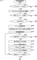
- 5 is a flowchart illustrating an operation of a communication device on the data transmission side.
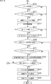
- 5 is a flowchart illustrating an operation of a communication device on the data transmission side.
- 5 is a flowchart illustrating an operation of a communication device on the data receiving side.
- 5 is a flowchart illustrating an operation of a communication device on the data receiving side.
- Conventional wireless LAN systems employ, for example, a technology that simultaneously transmits data on two adjacent frequency channels, or a channel bonding technology that can simultaneously use up to eight channels and a frequency bandwidth of 160 MHz.
- a technology that simultaneously transmits data on two adjacent frequency channels or a channel bonding technology that can simultaneously use up to eight channels and a frequency bandwidth of 160 MHz.
- the communication speed has been increased, but since demand for higher speeds is expected to increase in the future, communication using more frequency channels is expected. Is assumed to be implemented.
- a conventional communication method using a multi-channel includes a method in which a predetermined access control is performed on a primary channel to enable access to a transmission path. If the secondary channel is not used, communication can be performed using the secondary channel in addition to the primary channel.
- channel information allocated in advance to each terminal is transmitted to the RTS (Request @ to A technique of transmitting data as a Send (Send) frame (multi-user RTS) and receiving data of a CTS (Clear to Send) frame from each terminal is disclosed.
- the RTS frame and the CTS frame are exchanged before data transmission, and the network allocation vector (NAV: Network Allocation Vector) is exchanged with the surrounding communication devices.
- NAV Network Allocation Vector
- NAV network allocation vector
- the network allocation vector (NAV) is set for the duration of the duration described in both the RTS frame and the CTS frame. Therefore, even if the communication device that has transmitted the RTS frame has not detected the use of the transmission path, the communication device that has transmitted the CTS frame has detected the signal, or the communication device that has transmitted the CTS frame has detected a signal from an adjacent basic service set (BSS: Basic Service Set) If the network allocation vector (NAV) is set by the signal of (1), there is a problem that the CTS frame cannot be returned (reply), and data cannot be transmitted / received.
- BSS Basic Service Set
- the duration of the Duration is maintained even though data is not transmitted or received. There has been a problem that other communication devices cannot perform transmission over the period.
- a data transmission channel is allocated to each terminal in advance by an access point, and a basic service set (BSS) that overlaps on the terminal side is provided. If the network allocation vector (NAV) from the communication device is not set, the multi-user RTS cannot respond to CTS frames, cannot transmit data, and enables frequency channels. There was a problem that it could not be used for
- the transmission (return) of the ACK (Acknowledgement) frame is requested after the transmission of the data is completed, the ACK frame is transmitted when the communication device of another overlapping network is receiving. There is a problem that the transmission collides with the reception.
- This technology solves the above-mentioned problem and proposes a communication method (new method) for performing communication on an empty channel according to the usage status of a plurality of frequency channels.
- a communication device e.g., a base station
- receives information hereinafter, referred to as a transmittable frequency channel selected from available frequency channels.
- Generating a request signal for example, a request frame such as an MCH_RTS frame
- bandwidth information information regarding a bandwidth (number of frequency channels) of a frequency used for data transmission.
- the request signal thus transmitted is transmitted to a communication device on the receiving side (for example, a terminal station).
- a communication device for example, a terminal station on the data reception side receives a request signal (for example, an MCH_RTS frame) transmitted from a communication device (for example, a base station) on the transmission side and includes the request signal in the received request signal.
- a request signal for example, an MCH_RTS frame
- a receivable frequency channel is selected from receivable frequency channels based on channel information and bandwidth information received, and a response signal (for example, a response frame such as a CTS frame or the like) is ) Is transmitted to the communication device on the transmission side (for example, a base station).
- the communication device e.g., a base station
- receives a response signal e.g., a CTS frame
- receives the response signal e.g., a CTS frame
- the data is transmitted to the communication device (for example, the terminal station) on the receiving side by using the frequency channel selected as the frequency channel that can be received by the terminal station.
- a CTS frame used in the current system is transmitted as a response frame (response signal) to notify surrounding communication devices of reception use, and a network allocation vector corresponding to the reception duration time is transmitted.
- a network allocation vector corresponding to the reception duration time is transmitted.
- a communication device for example, a base station
- uses a first frequency channel for example, frequency channels f3 and f4 to transmit data (for example, frequency channels f3 and f4).
- a data frame is transmitted to a communication device on the receiving side (for example, a terminal station).
- a communication device for example, a terminal station
- uses a first frequency channel for example, frequency channels f3 and f4 to transmit data from a communication device (for example, a base station) on the transmitting side.
- Receive data eg, data frames).
- a signal for requesting confirmation of normal reception of data for example, a data frame
- a signal for requesting confirmation of normal reception of data for example, a data frame
- a request signal for example, BAR
- BAR including information (channel information) on a transmittable frequency channel (for example, a frequency channel on which a receiving communication device (for example, a terminal station) can transmit an acknowledgment signal (for example, ACK frame)) selected from A request frame such as a frame
- the generated request signal for example, a BAR frame
- a second frequency channel for example, a frequency channel f1 different from the frequency channels f3 and f4
- a communication device for example, a terminal station
- uses a second frequency channel for example, frequency channel f1 to transmit a request signal transmitted from a communication device (for example, a base station) on the transmitting side.
- a frequency channel is selected from transmittable frequency channels based on channel information included in the received request signal.
- the acknowledgment signal for example, ACK frame
- the communication device for example, base station
- the request frame (request signal) is a BAR (Block Ack Request) frame
- a frame responding to the request frame (request signal) is an ACK frame used in the current method, so that the ACK frame is reliably returned. Becomes possible.
- FIG. 1 is a diagram illustrating an example of a configuration of a wireless network.
- the wireless network of the basic service set BSS includes a base station AP10, a terminal station STA11, and a terminal station STA12. Further, the base station AP20, the terminal station STA21, and the terminal station STA22 constitute a wireless network of an overlapping basic service set OBSS adjacent thereto.
- the terminal station STA12 of the basic service set BSS and the terminal station STA21 of the basic service set OBSS exist at positions where they can receive each other's signals (dotted arrow A1 in the figure).
- the transmission of the signal by the terminal station STA causes interference with the reception of the other terminal station STA.
- FIG. 2 is a diagram illustrating an example of access control of a wireless network according to a current scheme, based on the configuration of the wireless network illustrated in FIG. 1.
- FIG. 2 shows an access control sequence exchanged between the base station AP10 and the terminal station STA12 of the basic service set BSS and the terminal station STA21 and the base station AP20 of the basic service set OBSS.
- the configuration is such that the radio waves of the STA reach.
- the RTS frame is transmitted from the base station AP10 of the basic service set BSS and the base station AP20 of the basic service set OBSS (S1, S11), respectively.
- the STA 21 responds with a CTS frame (S2, S12).
- FIG. 3 is a diagram illustrating an example of access control of a wireless network according to a new method on the assumption that the configuration of the wireless network illustrated in FIG. 1 is assumed.
- FIG. 3 shows an access control sequence exchanged between the base station AP10 and the terminal station STA12 of the basic service set BSS and the terminal station STA21 and the base station AP20 of the basic service set OBSS, similarly to FIG. , The radio waves of the adjacent terminal stations STA arrive.
- the MCH_RTS frame is transmitted from the base station AP10 of the basic service set BSS and the base station AP20 of the basic service set OBSS on the same frequency channel (f1) (S21, S31).
- the terminal stations STA12 and STA21 that have received the MCH_RTS frame respectively select available frequency channels and respond with a CTS frame.
- the terminal station STA12 returns a CTS frame using the frequency channel (f3) (S22), while the terminal station STA21 returns a CTS frame using the frequency channel (f2) (S32). .
- the base station AP10 and the base station AP20 receive the CTS frame on different frequency channels (f3, f2). Then, the base station AP10 transmits a data frame using the frequency channel (f3) (S23), while the base station AP20 transmits a data frame using the frequency channel (f2). (S33).
- f3 frequency channel
- f2 frequency channel
- S33 data frame using the frequency channel
- the MCH_BAR frame is transmitted from the base station AP20 to the terminal station STA21 using the predetermined frequency channel (f1) (S34).
- the terminal station STA21 since the terminal station STA21 has detected the CTS frame of the frequency channel (f3), the terminal station STA21 selects the frequency channel (f2) excluding the CTS frame and transmits the ACK frame using the selected frequency channel (f2). It is returned (S35).
- a data frame is transmitted from the base station AP10 to the terminal station STA12 (S23). However, since the data frame is transmitted using the frequency channel (f3), no signal collision occurs.
- the channel information on the available frequency channel is described in the request frame (for example, the MCH_RTS frame or the MCH_BAR frame) transmitted from the base station AP, and the terminal station STA
- a response frame for example, a CTS frame or an ACK frame
- an MCH_BAR frame is transmitted from the base station AP10 to the terminal station STA12 by using a predetermined frequency channel (f1) (S24), and the terminal station STA12 removes the frequency except for the frequency channel (f2).
- the channel (f3) is selected, and an ACK frame is returned using the selected frequency channel (f3) (S25).
- a data frame is transmitted from the base station AP20 to the terminal station STA21 (S36), but no signal collision occurs because the data frame is transmitted using the frequency channel (f2).
- FIG. 4 is a diagram illustrating an example of an arrangement of frequency channels that can be used in the wireless LAN system.
- FIG. 4 shows a channel arrangement in, for example, a 5 GHz band which is a currently available frequency band.
- Channels 36, 40, 44, 48, 52, 56, 60 and 64 are arranged from A in FIG.
- channels 100, 104, 108, 112, 116, 120, 124, 128, 132, 136, 140 and 144 are arranged in units of 20 MHz.
- FIG. 4B shows a configuration in which a frequency channel is used in units of 40 MHz. At low frequencies according to the center frequency, channels 38, 46, 54, and 62 are arranged, and at high frequencies, Here, channels 102, 110, 118, 126, 134 and 142 are arranged.
- FIG. 4C shows a configuration in which a frequency channel is used in units of 80 MHz.
- Channels 42 and 58 are arranged at a low frequency according to the center frequency, and channel 106 is arranged at a high frequency.
- 122, 138 are arranged.
- D (fourth stage) in FIG. 4 shows a configuration in the case where a frequency channel is used in units of 160 MHz.
- a channel 50 is arranged at a low frequency according to the center frequency, and a channel 114 is arranged at a high frequency. Is done.
- E (fifth stage) in FIG. 4 and F (sixth stage) in FIG. 4 show configurations in which more frequency channels are bundled and used. , And a case where a 320 MHz channel is used over low and high frequencies.
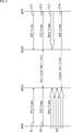
- FIG. 5 is a diagram showing an example of a multi-channel access control procedure according to the new method.
- FIG. 5 shows a procedure of performing multi-channel access control using four frequency channels from f1 to f4 for convenience of description, but the number of frequency channels is an example, and three or less frequency channels are used. Alternatively, access control may be performed using five or more frequency channels.
- ⁇ Circle around (A) ⁇ of FIG. 5 that is, the first stage in the figure represents the operation of the base station AP10, the vertical axis represents the frequency channel (f), and the horizontal axis represents time (t).
- the base station AP10 determines the destination (reception side).
- An MCH_RTS frame containing the channel information and the bandwidth information (“MCH_RTS” in FIG. 5A) is transmitted to the terminal station STA12 using the predetermined frequency channel f1.
- frequency channels f1 to f4 are described as channel information, and two channels (for example, 40 MHz) are described as bandwidth information.
- the base station AP10 waits for reception of a response frame (CTS frame) to the MCH_RTS frame as a request frame on the frequency channels f1 to f4 determined to be available for its own transmission.
- CTS frame a response frame
- a CTS frame (“Rx” in FIG. 5A corresponding to “CTS” in FIG. 5B) from the receiving terminal station STA12 is received on the frequency channels f3 and f4.
- the base station AP10 transmits a data frame (“Data” in FIG. 5A) to the terminal station STA12 using the frequency channels f3 and f4.
- the base station AP10 determines that the frequency channels f1 to f4 that are not used in its surroundings are available for its own transmission, the base station AP10 receives the data frame and receives the data frame. Then, an MCH_BAR frame including the channel information (“MCH_BAR” in FIG. 5A) is transmitted using a predetermined frequency channel f1. For example, in this MCH_BAR frame, frequency channels f1 to f4 are described as channel information.
- the frequency channel (f3, f4) used when transmitting the data frame and the frequency channel (f1) used when transmitting the MCH_BAR frame are different frequency channels.
- the base station AP10 waits for reception of a response frame (ACK frame) for the MCH_BAR frame as a request frame on the frequency channels f1 to f4 determined to be available for its own transmission.
- ACK frame a response frame
- an ACK frame (“Rx” in FIG. 5A corresponding to “ACK” in FIG. 5B) from the receiving terminal station STA12 is received on the frequency channel f3 in this example.
- BB (second stage) in FIG. 5 shows the operation of the terminal station STA12, in which the vertical axis represents the frequency channel (f) and the horizontal axis represents time (t).
- the horizontal axis of B (second stage) in FIG. 5 also corresponds to the time series of the horizontal axis of A (first stage) in FIG. 5, and the times t22 to t27 in FIG. These correspond to time t11 to time t16 in FIG.
- the terminal station STA12 transmits a CTS frame from the terminal station STA21 existing therearound on the frequency channel f2 (“CTS” in FIG. 5B corresponding to “CTS” in FIG. 5C).
- CTS in FIG. 5B corresponding to “CTS” in FIG. 5C.
- Rx ") a network allocation vector ( BUSY / NAV "in FIG. 5B) up to the duration of subsequent data reception is set for the frequency channel f2.
- the terminal station STA12 receives an MCH_RTS frame (“Rx” in FIG. 5B corresponding to “MCH_RTS” in FIG. 5A) addressed to itself from the base station AP10 on the predetermined frequency channel f1. I do.
- MCH_RTS frame frequency channels f1 to f4 are described as channel information, and two channels (for example, 40 MHz) are described as bandwidth information.
- the terminal station STA12 sets the network allocation vector (NAV) for the frequency channel f2 among the frequency channels f1 to f4 described in the channel information included in the MCH_RTS frame.
- the reception time (transmission time) of a data frame can be reduced.
- the terminal station STA12 transmits a CTS frame (“CTS” in FIG. 5B) to the base station AP10 using the selected frequency channels f3 and f4. Thereby, between time t24 and time t25, the terminal station STA12 uses the frequency channels f3 and f4 to transmit the data frame from the base station AP10 (corresponding to “Data” in FIG. 5A corresponding to “Data” in FIG. 5A). B “Rx”) is received.
- CTS CTS frame
- the terminal station STA12 performs reception standby on the frequency channels f1 to f4 previously designated as available by the base station AP10, and in this example, The MCH_BAR frame (“Rx” in FIG. 5B corresponding to “MCH_BAR” in FIG. 5A) from the base station AP10 is received on the predetermined frequency channel f1.
- frequency channels f1 to f4 are described as channel information.
- the terminal station STA12 since the network allocation vector (NAV) is set for the frequency channel f2, or because it is the timing of receiving the ACK frame from the terminal station STA21, the terminal station STA12 transmits the frequency channels f1 to f4. Among them, the frequency channel f3 excluding the frequency channel f2 is selected. Then, at time t27, the terminal station STA12 transmits an ACK frame (“ACK” in FIG. 5B) to the base station AP10 using the selected frequency channel f3.
- NAV network allocation vector
- CC (third stage) in FIG. 5 represents the operation of the terminal station STA21, in which the vertical axis represents the frequency channel (f) and the horizontal axis represents time (t).
- the horizontal axis of C (third stage) in FIG. 5 also corresponds to the time series of the horizontal axis of B (second stage) in FIG. 5, and the time t32 in FIG.
- the time t21 of B and the time t34 of C in FIG. 5 correspond to the time t23 of B in FIG. 5, respectively.
- the terminal station STA21 uses an MCH_RTS frame addressed to itself from the base station AP20 on a predetermined frequency channel f1 (“MCH_RTS” in FIG. 5C corresponding to “MCH_RTS” in FIG. 5D).
- MCH_RTS frequency channel
- Rx frequency channels f1 to f4 are described as channel information, and one channel (for example, 20 MHz) is described as bandwidth information.
- the terminal station STA21 assigns one of the frequency channels f2 (for example, 20 MHz) to the frequency channels f1 to f4 described in the channel information included in the MCH_RTS frame since there is no frequency channel used in the surroundings. select.
- the terminal station STA21 transmits a CTS frame (“CTS” in FIG. 5C) to the base station AP20 using the selected frequency channel f2.
- CTS CTS frame
- the terminal station STA21 uses the frequency channel f2 to transmit a data frame from the base station AP20 (corresponding to “Data” in FIG. 5D in FIG. 5C). “Rx”).
- the terminal station STA21 performs reception standby on the frequency channels f1 to f4 designated as usable by the base station AP20.
- the frequency channels f3 and f4 are set at time t34.
- a network allocation vector (“BUSY / NAV” in FIG. 5C) up to the duration of data reception is set.
- the base station AP20 waits for reception on the frequency channels f1 to f4 previously designated as available, and in this example, the predetermined frequency channel At f1, an MCH_BAR frame (“Rx” in FIG. 5C corresponding to “MCH_BAR” in D in FIG. 5) from the base station AP20 is received.
- MCH_BAR frame (“Rx” in FIG. 5C corresponding to “MCH_BAR” in D in FIG. 5) from the base station AP20 is received.
- frequency channels f1 to f4 are described as channel information.
- the terminal station STA21 since the network allocation vector (NAV) is set for the frequency channels f3 and f4, the terminal station STA21 selects the frequency channel f2 excluding the frequency channels f3 and f4 from the frequency channels f1 to f4. I do. Then, at time t37, the terminal station STA21 transmits an ACK frame (“ACK” in FIG. 5C) to the base station AP20 using the selected frequency channel f2.
- ACK ACK frame
- the horizontal axis of D in FIG. 5 also corresponds to the time series of the horizontal axis of C (third stage) in FIG. 5, and the time t41 to the time t46 in D in FIG. These correspond to time t31 to time t37 (excluding time t34).
- the base station AP20 determines whether the reception destination (reception side) An MCH_RTS frame (“MCH_RTS” in FIG. 5D) including channel information and bandwidth information is transmitted to the terminal station STA21 by using a predetermined frequency channel f1.
- MCH_RTS MCH_RTS frame
- frequency channels f1 to f4 are described as channel information, and one channel (for example, 20 MHz) is described as bandwidth information.
- the base station AP20 waits for reception of the CTS frame for the MCH_RTS frame on the frequency channels f1 to f4 which are determined to be available for its own transmission.
- the channel f2 receives a CTS frame (“Rx” in FIG. 5D corresponding to “CTS” in FIG. 5C) from the receiving terminal station STA21.
- the base station AP20 transmits a data frame (“Data” in FIG. 5D) to the terminal station STA21 using the frequency channel f2.
- an MCH_BAR frame including channel information (“MCH_BAR” in FIG. 5D) is transmitted using a predetermined frequency channel f1.
- MCH_BAR channel information
- the frequency channel (f2) used when transmitting the data frame and the frequency channel (f1) used when transmitting the MCH_BAR frame are different frequency channels.
- the base station AP20 performs reception standby on the frequency channels f1 to f4 determined to be able to use the ACK frame for the MCH_BAR frame in its own transmission.
- the ACK frame (“Rx” in FIG. 5D corresponding to “ACK” in FIG. 5C) from the receiving terminal station STA21 is received on the frequency channel f2.
- a data frame when a data frame is transmitted from the base station AP to the terminal station STA, a plurality of MCH_RTS frames including channel information and bandwidth information are transmitted.
- Data frames can be transmitted and received using an empty channel (f3, f4, f2, etc.) according to the use status of the frequency channel (f1 to f4, etc.).
- the base station AP receives the ACK frame from the terminal station STA, it transmits an MCH_BAR frame including the channel information, so that an available channel (f1 to f4, etc.) according to the use status of a plurality of frequency channels (f1 to f4, etc.).
- ACK frames can be transmitted and received using f3 and f2).
- FIG. 6 is a diagram illustrating an example of the configuration of a data frame.
- the frame configuration shown in FIG. 6 is called MPDU (MAC Protocol Data Unit) and is transmitted following the PHY layer preamble signal.
- MPDU MAC Protocol Data Unit
- the data frame includes Frame Control, Duration, Address1 to Address4, Sequence Control, QoS Control, HT Control, Frame Body, and FCS.
- ⁇ Frame ⁇ Control describes frame control information and the type of frame. Duration describes the duration of the frame. Address1 to Address4 describe address information for identifying a transmission source and a reception destination.
- ⁇ Sequence ⁇ Control describes sequence number information for performing frame sequence control.
- QoS Control describes parameters for QoS control of the frame.
- HT Control describes parameters for high-throughput control.
- the data portion actually transmitted with respect to the MAC header is configured as Frame @ Body, and an FCS (Frame @ Check @ Sequence) for error detection is added to the end.
- FCS Fre @ Check @ Sequence
- FIG. 7 is a diagram illustrating an example of a configuration of a multi-channel RTS frame (MCH_RTS frame) to which the present technology is applied.
- the MCH_RTS frame includes Frame Control, Duration, Transmit Address, Receive Address, Available Channel Map, Requirement Bandwidth, and FCS.
- the MCH_RTS frame includes a Duration in which the duration of transmission is described, a Transmit @ Address (TA) in which the transmission address is described, a Receive @ Address (RA) in which the reception address is described, and a frame of the frame included in the current RTS frame.
- TA Transmit @ Address
- RA Receive @ Address
- FCS Available Channel Map and Requirement Bandwidth
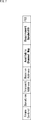
- the Available ⁇ Channel ⁇ Map includes a transmittable frequency channel selected from available frequency channels, that is, a channel related to a frequency channel through which a communication device (eg, a base station AP) on the transmitting side can transmit data (eg, a data frame). Information is described.
- FIG. 8 shows an example in which Available ⁇ Channel ⁇ Map is represented in a bitmap format.
- each bit of the 32-bit bit map is represented by a number from 0 to 31.
- the first bit 0 is expressed as 36 channels
- the next bit 1 is expressed as 40 channels
- the last bit 31 is expressed as 160 channels
- an available frequency channel is allocated to each bit.
- the bit corresponding to the transmittable frequency channel is set to "1"
- the other bits are set to "0". Can be.
- the channel information is expressed in the bitmap format, the present invention is not limited to such a format, and any other format may be used as the channel information as long as the channel number can be specified. You may make it.
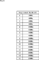
- ⁇ Requirement ⁇ Bandwidth describes bandwidth information relating to the bandwidth (number of frequency channels) of the frequency used for data transmission.
- FIG. 9 illustrates an example of a case where the bandwidth of the frequency to be used is represented in association with a numerical value as Requirement @ Bandwidth.
- a numerical value 0 is a 20 MHz bandwidth
- a numerical value 1 is a 40 MHz bandwidth
- the bandwidth also increases, and the numerical value 15 can be designated as the bandwidth (the number of channels) using the bandwidth of 320 MHz.
- a bandwidth of 20 MHz corresponds to the number of channels of 1
- a bandwidth of 40 MHz is 2, for example. This corresponds to the number of channels.
- FIG. 10 is a diagram illustrating an example of the configuration of a CTS frame.
- the CTS frame includes Frame Control, Duration, Receive Address, and FCS.
- the CTS frame is composed of Duration indicating the duration of transmission, Receive @ Address (RA) indicating the reception address, and FCS at the end of the frame, like the current CTS frame.
- RA Receive @ Address
- FCS FCS at the end of the frame, like the current CTS frame.
- the CTS frame has the same configuration as that of the current state, so that compatibility with the wireless LAN system of the current method can be maintained.
- FIG. 11 is a diagram illustrating an example of a configuration of a multi-channel BAR frame (MCH_BAR frame) to which the present technology is applied.
- the MCH_BAR frame includes Frame Control, Duration, Transmit Address, Receive Address, Available Channel Map, BA Control, BA Information, and FCS.
- the MCH_BAR frame includes a Duration that describes the duration of transmission, a Transmit @ Address (TA) that describes a transmission address, a Receive @ Address (RA) that describes a reception address, and a block ACK included in the current BAR frame.
- TA Transmit @ Address
- RA Receive @ Address
- BA @ Information in which information on a required block ACK is described, and FCS at the end of a frame, Available @ Channel @ Map (a parameter thereof) is newly added.
- the Available ⁇ Channel ⁇ Map is a transmittable frequency channel selected from available frequency channels, such as the information in the bitmap format shown in FIG. 8, for example, a communication device on the receiving side (for example, the terminal station STA). ) Describes channel information about a frequency channel that can transmit a confirmation signal (for example, an ACK frame). In other words, it can be said that the channel information is a frequency channel in which the communication device on the transmission side (for example, the base station AP) can transmit a request signal (for example, an MCH_BAR frame).
- the information (ACK information) of the returned ACK frame is short information (information with a small amount of data) unlike the data. Therefore, in the MCH_BAR frame, the Requirement Bandwidth parameter is omitted as compared with the configuration of the MCH_RTS frame. be able to.
- FIG. 12 is a diagram illustrating an example of the configuration of a block ACK frame.
- the block ACK frame includes Frame Control, Duration, Transmit Address, Receive Address, BA Control, BAformInformation, and FCS.
- the block ACK frame is, like the current block ACK frame, a Duration in which the transmission duration is described, a Transmit @ Address (TA) in which the transmission address is described, a Receive @ Address (RA) in which the reception address is described, It is composed of BA @ Control in which control information of the block ACK is described, BA @ Information in which information on a required block ACK is described, and FCS at the end of the frame.
- the block ACK frame has the same configuration as that of the current state, thereby maintaining compatibility with the wireless LAN system of the current method.
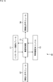
- FIG. 13 is a block diagram illustrating an example of a configuration of a communication device (wireless communication device) to which the present technology is applied.
- the communication device 10 illustrated in FIG. 13 is configured as a base station AP or a terminal station STA in a wireless network (FIG. 1).
- the communication device 10 includes an Internet connection module 11, an information input module 12, a device control unit 13, an information output module 14, and a wireless communication module 15.
- the Internet connection module 11 includes, for example, a circuit having a function of connecting to an Internet network from a fiber optic network or other communication line as a base station AP via a service provider, a peripheral circuit thereof, a microcontroller, a semiconductor memory, and the like. Is done.
- the Internet connection module 11 performs processing related to Internet connection according to the control from the device control unit 13.
- the Internet connection module 11 has a configuration in which a function such as a communication modem for connecting to the Internet network is mounted when the communication device 10 operates as the base station AP.
- the information input module 12 is composed of input devices such as push buttons, a keyboard, and a touch panel.
- the information input module 12 has a function of inputting instruction information corresponding to an instruction from a user to the device control unit 13.
- the device control unit 13 includes, for example, a microprocessor and a microcontroller.
- the device control unit 13 controls each unit (module) in order to operate the communication device 10 as the base station AP or the terminal station STA.
- the device control unit 13 performs processing on information supplied from the Internet connection module 11, the information input module 12, or the wireless communication module 15. Further, the device control unit 13 supplies information obtained as a result of its own processing to the Internet connection module 11, the information output module 14, or the wireless communication module 15.
- the device control unit 13 supplies transmission data passed from an application of a protocol upper layer or the like to the wireless communication module 15 at the time of data transmission or receives data supplied from the wireless communication module 15 at the time of data reception.
- a protocol upper layer for example, the device control unit 13 supplies transmission data passed from an application of a protocol upper layer or the like to the wireless communication module 15 at the time of data transmission or receives data supplied from the wireless communication module 15 at the time of data reception.
- the information output module 14 is configured by an output device including a display element such as a liquid crystal display (LCD: Liquid Crystal Display), an organic EL display (OLED: Organic Light Emitting Diode), and an LED (Light Emitting Diode) display.
- a display element such as a liquid crystal display (LCD: Liquid Crystal Display), an organic EL display (OLED: Organic Light Emitting Diode), and an LED (Light Emitting Diode) display.
- the information output module 14 has a function of displaying necessary information to the user based on information supplied from the device control unit 13.
- the information processed by the information output module 14 includes, for example, an operation state of the communication device 10 and information obtained via the Internet network.
- the wireless communication module 15 includes, for example, a wireless chip, peripheral circuits, a microcontroller, a semiconductor memory, and the like.
- the wireless communication module 15 performs a process related to wireless communication according to control from the device control unit 13. Details of the configuration of the wireless communication module 15 will be described later with reference to FIG.
- a wireless communication module equipped with a wireless communication chip, peripheral circuits, and the like will be described as an example, but the present technology is not limited to the wireless communication module, and is applied to, for example, a wireless communication chip, a wireless communication LSI, and the like. be able to. Further, whether or not the wireless communication module includes an antenna is optional.
- the device control unit 13 and the wireless communication module 15 are essential components, but the Internet connection module 11, the information input module 12, and the information output module 14 other than those are included. Inclusion in the element is optional.
- each communication device 10 operating as the base station AP or the terminal station STA can be configured with only required modules, and unnecessary portions can be simplified or not incorporated. It can be. More specifically, for example, the Internet connection module 11 can be incorporated only into the base station AP, and the information input module 12 and the information output module 14 can be incorporated only into the terminal station STA.
- FIG. 14 is a block diagram showing an example of the configuration of the wireless communication module 15 in FIG.
- the wireless communication module 15 includes an interface 101, a transmission buffer 102, a network management unit 103, a transmission frame construction unit 104, a multi-channel management unit 105, a management information generation unit 106, a control frame transmission processing unit 107, a transmission power control Unit 108, wireless transmission processing unit 109, antenna control unit 110, wireless reception processing unit 111, detection threshold control unit 112, control frame reception processing unit 113, management information processing unit 114, reception data construction unit 115, and reception buffer 116. It is comprised including.
- the interface 101 is composed of, for example, an input / output interface circuit and the like.
- the interface 101 is an interface for exchanging data with the device control unit 13 (FIG. 13), and for exchanging information input thereto and information output therefrom in a predetermined signal format. It has the function of
- the interface 101 writes the transmission data input from the device control unit 13 to the transmission buffer 102.
- the interface 101 supplies information input from the device control unit 13 to the network management unit 103, or outputs information supplied from the network management unit 103 to the device control unit 13.
- the transmission buffer 102 is configured by a semiconductor memory device such as a buffer memory.
- the transmission buffer 102 temporarily stores the transmission data written via the interface 101.
- the network management unit 103 manages address information and the like of the communication device 10 in the wireless network. Further, the network management unit 103 is configured to connect to the Internet network when the communication device 10 operates as the base station AP.
- the transmission frame construction unit 104 reads the transmission data stored in the transmission buffer 102, constructs the data as a data frame to be transmitted by wireless communication, and supplies the data frame to the wireless transmission processing unit 109. Further, the transmission frame construction unit 104 supplies transmission frame information on the transmission frame to the management information generation unit 106.
- the multi-channel management unit 105 has a multi-channel management function for managing the usage status of a plurality of frequency channels.
- the multi-channel management unit 105 also has a function of monitoring the status of available frequency channels described in a request frame (request signal) and a response frame (response signal) and immediately grasping the available channels. I have.
- the multi-channel management unit 105 performs processing on information supplied from the network management unit 103, the detection threshold control unit 112, the control frame reception processing unit 113, or the management information processing unit 114. Further, the multi-channel management section 105 transmits information (multi-channel management information) obtained as a result of its own processing to the network management section 103, the management information generation section 106, the control frame transmission processing section 107, the transmission power control section 108, the antenna It is supplied to the control unit 110 or the detection threshold control unit 112.
- the transmission frame information from the transmission frame construction unit 104 and the multi-channel management information from the multi-channel management unit 105 are supplied to the management information generation unit 106.
- the management information generation unit 106 generates management information based on the transmission frame information and the multi-channel management information, and supplies the management information to the control frame transmission processing unit 107 and the wireless transmission processing unit 109.
- the management information includes, for example, header information of a frame actually transmitted by wireless communication and various parameters. For example, various parameters (for example, Available ⁇ ⁇ ⁇ ⁇ Channel Map, Requirement Bandwidth, etc.) of a multi-control frame such as an MCH_RTS frame and an MCH_BAR frame are also generated here and supplied to the control frame transmission processing unit 107.
- various parameters for example, Available ⁇ ⁇ ⁇ ⁇ Channel Map, Requirement Bandwidth, etc.
- the control frame transmission processing unit 107 is supplied with multi-channel management information from the multi-channel management unit 105, management information from the management information generation unit 106, and control frame reception information from the control frame reception processing unit 113.
- the control frame transmission processing unit 107 controls the wireless transmission processing unit 109 based on the multi-channel management information, the management information, and the control frame reception information to transmit a control frame (including a multi-control frame). I do.
- a function for centrally controlling the process for transmitting a multi-control frame such as an MCH_RTS frame or an MCH_BAR frame is provided. Has been added.
- the transmission power control unit 108 controls the transmission power to the wireless transmission processing unit 109 so that a signal does not reach an unnecessary radio wave reach when transmitting a predetermined frame.
- a function of controlling the transmission so as to adjust the necessary minimum transmission power so that the signal reaches the receiving side with the intended reception electric field strength and transmit data. Is provided.
- the wireless transmission processing unit 109 converts a frame transmitted by wireless communication into a baseband signal and processes it as an analog signal, and supplies a transmission signal obtained as a result of the processing to the antenna control unit 110.
- the wireless transmission processing unit 109 when transmitting a data frame, includes a data frame from the transmission frame construction unit 104 (a frame for transmitting transmission data) and management information from the management information generation unit 106 (the Data frame header information).
- the wireless transmission processing unit 109 generates a transmission signal corresponding to the data frame according to the control from the transmission power control unit 108 by including the header information in the data frame.
- the management information from the management information generation unit 106 is supplied to the wireless transmission processing unit 109.
- This management information includes various parameters of the control frame and the multi-control frame.
- the radio transmission processing unit 109 under the control of the control frame transmission processing unit 107 and the transmission power control unit 108, controls a control frame (CTS frame, ACK frame, etc.) or a multi-control frame (MCH_RTS frame, MCH_BAR frame, etc.) obtained from management information. ) Is generated.
- the antenna control unit 110 is configured by connecting a plurality of antenna elements.
- the antenna control unit 110 performs control for transmitting the transmission signal supplied from the wireless transmission processing unit 109 by wireless communication via the antenna element.
- the antenna control unit 110 receives a wireless signal transmitted by wireless communication via an antenna element, and supplies the wireless signal to the wireless reception processing unit 111 and the detection threshold control unit 112.
- the wireless reception processing unit 111 Is received.
- the wireless reception processing unit 111 supplies the header information of the data frame to the management information processing unit 114 and supplies the data frame to the received data construction unit 115.
- the wireless reception processing unit 111 supplies the control frame (including a multi-control frame) to the control frame reception processing unit 113 and the management information processing unit 114.
- the detection threshold control unit 112 can detect a radio signal from (the communication device 10 of) the base station AP or the terminal station STA within the range.
- the detection level of such a signal is set.
- a function is provided for controlling so as to detect a signal with a minimum necessary detection threshold.
- the control frame (including the multi-control frame) from the wireless reception processing unit 111 is supplied to the control frame reception processing unit 113.
- the control frame reception processing unit 113 performs a process for receiving a control frame (including a multi-control frame) supplied from the wireless reception processing unit 111, and divides the control frame reception information obtained as a result of the process into multi-channel management information.
- the information is supplied to the control unit 105, the control frame transmission processing unit 107, the detection threshold control unit 112, and the management information processing unit 114.
- a function for centrally controlling the processing when a multi-control frame such as an MCH_RTS frame or an MCH_BAR frame is received is provided. Has been added.
- the management information processing unit 114 is supplied with header information and control frames (including multi-control frames) from the wireless reception processing unit 111 and control frame reception information from the control frame reception processing unit 113.
- the management information processing unit 114 analyzes management information including header information and the like of a frame actually transmitted by wireless communication based on the header information, the control frame, and the control frame reception information, and converts the management information into reception address information. If specified, the parameters described in the frame are extracted.
- various parameters for example, Available Channel Map, Requirement Bandwidth, etc.
- a multi-control frame such as an MCH_RTS frame and an MCH_BAR frame
- the management information processing unit 114 supplies information such as header information obtained by analyzing the management information to the reception data construction unit 115.
- the received data construction unit 115 removes predetermined header information from the data frame from the wireless reception processing unit 111 based on information such as header information supplied from the management information processing unit 114, and only necessary data portions Is extracted and written to the reception buffer 116 as reception data.
- the reception buffer 116 is constituted by a semiconductor memory device such as a buffer memory.
- the reception buffer 116 temporarily stores the reception data written by the reception data construction unit 115.
- the reception data stored in the reception buffer 116 is appropriately read out and output to the device control unit 13 via the interface 101.
- the multi-channel management unit 105 the management information generation unit 106, the control frame transmission processing unit 107, the control frame reception processing unit 113, and the management information processing unit 114 Processing related to multiple control frames such as an MCH_RTS frame including channel information and bandwidth information and an MCH_BAR frame including channel information is performed.
- each unit configuring the wireless communication module 15 is divided into three blocks, for example, a transmission / reception data input / output unit 151, a control unit 152, and a front end unit 153, as indicated by a dotted frame. be able to.
- the transmission / reception data input / output unit 151 includes the interface 101, the transmission buffer 102, the network management unit 103, the transmission frame construction unit 104, the reception data construction unit 115, and the reception buffer 116. Processing and control relating to data and received data to be output are performed.
- the control unit 152 includes a multi-channel management unit 105, a management information generation unit 106, a control frame transmission processing unit 107, a control frame reception processing unit 113, and a management information processing unit 114. Processing and control relating to a frame such as a control frame are performed.
- the front end unit 153 includes a transmission power control unit 108, a wireless transmission processing unit 109, an antenna control unit 110, a wireless reception processing unit 111, and a detection threshold control unit 112, and mainly includes a transmission signal and a reception signal. The processing and control relating to the signal are performed.
- the wireless communication module 15 determines whether the transmission data has been received via the interface 101 (S101). If it is determined that the transmission data has been received (“YES” in S101), the received transmission data is transmitted. The data is stored in the buffer 102 (S102), and the processing after step S103 is executed.
- the multi-channel management unit 105 sets the number of frequency channels (bandwidth) required for transmission of transmission data from the amount of transmission data stored in the transmission buffer 102 (S103). Also, at this time, the multi-channel management unit 105 sets a random access time together with a predetermined access wait time in which priority is set according to the category of the transmission data (S104).
- the multi-channel management unit 105 grasps the usage status of the transmission paths of all the transmittable frequency channels (S105), and determines whether transmission of transmission data is possible (S106).
- S105 usage status of the transmission paths of all the transmittable frequency channels
- S106 determines whether transmission of transmission data is possible
- the processes of steps S105 and S106 are repeated, and when it is determined that transmission of the transmission data is possible (“YES” in S106), the process proceeds to step S107.
- Management information generating section 106 has channel information on a frequency channel capable of transmitting the transmission data (including a data frame) at a timing at which the transmission data can be transmitted, and a bandwidth relating to a bandwidth of a frequency used for transmission of the transmission data.
- the information is obtained and described in the MCH_RTS frame (Available Channel Map, Requirement Bandwidth) (S107).
- the control frame transmission processing unit 107 sets one frequency channel as a transmission channel from channel information described in (Available ⁇ Channel ⁇ Map) of the MCH_RTS frame (S108).
- the frequency channel that is the primary channel may be set as the transmission channel.
- the wireless transmission processing unit 109 transmits the MCH_RTS frame using the transmission channel set in the processing of step S108 (S109).
- control frame reception processing unit 113 performs a setting for waiting for the reception of the CTS frame on a plurality of frequency channels (ie, multi-channels as reception candidate channels) described as the channel information in the process of step S107 (S110). .
- the wireless communication module 15 determines whether or not a CTS frame has been received from the receiving communication device 10 (for example, the terminal station STA) on the plurality of frequency channels (reception candidate channels) set in the process of step S110. (S111), when it is determined that the CTS frame has been received (“YES” in S111), the multi-channel management unit 105 can receive the data frame of the target reception candidate channel by the receiving-side communication device 10. (S112).
- the multi-channel management unit 105 acquires the number of frequency channels (bandwidth) receivable by the communication device 10 (for example, the terminal station STA) on the receiving side, which is obtained by repeating the processing of steps S111 to S113 (S114). ).
- the multi-channel management unit 105 sets the number of frequency channels (bandwidth) necessary for transmitting transmission data (including data frames) in the communication device 10 (for example, the base station AP) on the transmission side set in the process of step S103. Is compared with the number of frequency channels (bandwidths) at which the transmission data (including data frames) can be received by the communication device 10 (eg, the terminal station STA) on the receiving side acquired in the processing of step S114. It is determined whether it is possible to set more than the number of frequency channels (bandwidth) (more than the number of requests) (S115).
- the multi-channel management unit 105 assigns one or more frequency channels capable of setting equal to or more than the requested number to the receiving destination. It is set as a receivable channel of the (reception-side communication device 10) (S116).
- the control frame transmission processing unit 107 sets the receivable channel of the destination set in the process of step S116 as the transmission channel of the transmission data (S117).
- the wireless transmission processing unit 109 transmits a data frame including transmission data using the transmission channel set in the process of step S117 (S118).
- a data frame including transmission data using the transmission channel set in the process of step S117 (S118).
- data frames and CTS frames from other communication devices 10 are transmitted. (S119).
- the wireless communication module 15 determines whether the ACK frame needs to be received (S120). If it is determined that the ACK frame needs to be received (“YES” in S120), the process from step S121 onward is performed. The processing is executed.
- the management information generation unit 106 acquires the channel information on the frequency channel on which the receiving communication device 10 (for example, the terminal station STA) can transmit the ACK frame at the timing when the ACK frame needs to be received, and obtains the MCH_BAR frame ( (Available ⁇ Channel ⁇ Map) (S121).
- the control frame transmission processing unit 107 sets one frequency channel as a transmission channel from the channel information described in (Available ⁇ Channel ⁇ Map) of the MCH_BAR frame (S122).
- the frequency channel that is the primary channel may be set as the transmission channel.
- the wireless transmission processing unit 109 transmits the MCH_BAR frame using the transmission channel set in the processing of step S122 (S123).
- the transmission channel (first frequency channel) used when transmitting the data frame (S118) is different from the transmission channel (second frequency channel) used when transmitting the MCH_BAR frame (S123).
- a frequency channel may be used.
- control frame reception processing unit 113 performs a setting to wait for reception of an ACK frame on a plurality of frequency channels (ie, multi-channels as reception candidate channels) described as channel information in the process of step S121 (S124). .
- the wireless communication module 15 determines whether an ACK frame has been received on any of the plurality of frequency channels (reception candidate channels) set in the process of step S124 (S125), and determines that the ACK frame has been received. If it is determined (“YES" in S125), of the transmission data stored in the transmission buffer 102, the transmission data whose reception has been confirmed by the ACK frame is deleted (S126).
- step S120 If it is determined in the determination processing of step S120 that the reception of the ACK frame is unnecessary (“NO” in S120), the processing related to the ACK frame (S121 to S125) is skipped, and the processing proceeds to step S126. Then, the transmission data stored in the transmission buffer 102 is deleted (S126). When the processing of step S126 ends, the processing shown in the flowcharts of FIGS. 15 and 16 ends.
- step S115 when it is determined that the number of frequency channels (bandwidth) required for transmission of transmission data is not uniform (“NO” in S115), in the determination process of step S125, an ACK frame is used. If it is determined that there is transmission data for which reception cannot be confirmed (“NO” in S125), the process returns to step S103, and the number of frequency channels (bandwidth) necessary for transmission is selected again. . If it is determined in the determination processing of step S101 that the transmission data has not been received (“NO” in S101), the processing is terminated without performing the subsequent processing itself.
- the wireless communication module 15 determines whether or not the wireless communication module 15 is (the wireless communication module 15 of) the multi-channel compatible communication device 10 (S201). If it is determined in step S201 that the user is multi-channel compatible and the user desires to set up communication using multi-channel (“YES” in S201), the wireless communication module 15 Is set to wait for the reception at step S202 (S202), and the processes after step S203 are executed.
- the control frame reception processing unit 113 sends the MCH_RTS frame addressed to itself (a request to use itself as a destination). Is determined (S204).
- the control frame reception processing unit 113 acquires the channel information described in (Available Channel Map) of the MCH_RTS frame addressed to itself (S205). ), The transmission side communication device 10 (for example, the base station AP) grasps the use status of the transmission paths of all the frequency channels to which the transmission data (including the data frame) can be transmitted (S206).
- the control frame reception processing unit 113 acquires bandwidth information described in (Requirement @ Bandwidth of) the MCH_RTS frame addressed to itself (S207). Then, based on the channel information and the bandwidth information, the multi-channel management section 105 determines whether or not there is a receivable frequency channel among itself in the receivable frequency channels (S208).
- control frame transmission processing section 107 sets that frequency channel as a receivable channel (S209) and performs data transmission. Is set as Duration information (S210). Thereby, the wireless transmission processing unit 109 transmits the CTS frame using the receivable channel set in the processing of step S209 (S211).
- the control frame reception processing unit 113 performs a setting to wait for reception of a data frame on the receivable channel set in the process of step S209 (S212).
- the receivable channel selected from the receivable frequency channels is a reception channel for receiving a data frame and a transmission channel for transmitting a CTS frame.
- the setting of the receivable channel is performed until the communication device 10 (the wireless communication module 15 thereof) on the data transmission side such as the base station AP10 in FIG. 5 determines all the frequency channels that can be transmitted. ("YES" in S213), the process returns to step S208, and the processes in steps S208 to S213 are repeated.
- the receiving communication device 10 eg, the terminal station STA
- select the transmission data eg, the terminal station STA
- the transmitting communication device 10 eg, the base station AP
- a data frame including the data frame can be selected, and the bandwidth of the frequency used for transmitting the data frame can be secured (the number of frequency channels required for transmitting the data frame is secured). Is possible).
- the wireless communication module 15 determines whether a data frame has been received on the receivable channel set by repeating the processing of steps S208 to S213 (S214), and has determined that the data frame has been received. In this case (“YES" in S214), it is further determined whether or not the received data stored in the data frame has been normally received (S215).
- the wireless communication module 15 determines that the received data has been successfully received (“YES” in S215), the wireless communication module 15 stores the received data in the reception buffer 116 (S216), and sets the sequence number as the ACK information. Are constructed (S217). In addition, the wireless communication module 15 determines whether or not all the received data have been collected (S218). If all of the received data have been collected (“YES” in S218), the received data stored in the reception buffer 116 is determined. Is output to the application in the upper layer of the protocol via the interface 101 (S219).
- step S219 the process proceeds to step S220.
- step S220 it is determined that the data frame has not been received (“NO” in S214), when it is determined that the received data has not been received normally (“NO” in S215), If it is determined that they are not aligned (“NO” in S218), the process proceeds to step S220.
- the communication apparatus 10 (base station AP) on the data transmission side sets the CTS frame according to the reception. If it is determined that it is not possible to set the number of required frequency channels (bandwidth) or more (more than the requested number) by the receivable channel (“NO” in S115 of FIG. 16), the data frame is not The transmission is performed (S118 in FIG. 16 is not performed), and the communication apparatus 10 (terminal station STA) on the data receiving side determines that the data frame is not received (“NO” in S214).
- the wireless communication module 15 determines whether it is necessary to return an ACK frame (S220). If it is determined that the ACK frame is required to be returned (“YES” in S220), the wireless communication module 15 further determines itself. It is determined whether or not it is compatible with multi-channel (S221). Then, when it is determined that it is compatible with the multi-channel ("YES" in S221), the multi-channel management unit 105 grasps the use status of the transmission paths of all the transmittable frequency channels (S222). .
- the wireless communication module 15 determines whether an MCH_BAR frame has been received (S233). When it is determined that the MCH_BAR frame has been received (“YES” in S233), the control frame reception processing unit 113 transmits the ACK to the communication device 10 on the receiving side described in the (Available ⁇ Channel ⁇ Map of) the MCH_BAR frame. Channel information on a frequency channel capable of transmitting a frame (for example, the terminal station STA) is obtained (S224).
- the transmission channel (first frequency channel) used when receiving the data frame (S214) and the transmission channel (second frequency channel) used when receiving the MCH_BAR frame (S223) are as follows: There may be different frequency channels, and reception is performed on all channels.
- the control frame transmission processing unit 107 sets at least one channel frequency in the channel information acquired in the process of step S224 as a transmission channel (S225). Thereby, the wireless transmission processing unit 109 transmits an ACK frame using the transmission channel set in the process of step S225 (S226).
- step S221 If it is determined in the determination process of step S221 that the device itself does not support multi-channel ("NO" of S221), the processes of steps S222 to S225 are skipped, and the ACK frame is transmitted using a single transmission channel. Is transmitted (S226). If it is determined in the determination processing in step S220 that transmission of an ACK frame is unnecessary ("NO" in S220), the processing in steps S221 to S226 is skipped, and the ACK frame is not transmitted. When the processing in step S226 ends, the processing shown in the flowcharts of FIGS. 17 and 18 ends.
- step S203 If it is determined in the determination process of step S203 that the MCH_RTS frame has not been received (“NO” in S203), it is determined in the determination process of step S204 that the frame is an MCH_RTS frame addressed to another communication device 10. If (NO in S204) or in the determination process in step S208, it is determined that there is no receivable frequency channel (“NO" in S208), the process proceeds to step S214, A frame receiving operation is performed.
- a request frame including information on channel resources (channel information) available in the communication device 10 (for example, the base station AP) and information on the amount of channel with a 20 MHz bandwidth (bandwidth information) is transmitted.
- channel information channel information
- bandwidth information information on the amount of channel with a 20 MHz bandwidth
- the communication device 10 for example, the base station AP
- the communication device 10 for example, the terminal station STA
- a plurality of frequency channels are used. Communication can be performed on an empty channel according to the usage status. That is, communication can be performed using a frequency channel that is not used by an overlapping basic service set (BSS). For example, as shown in FIG. 4, when a frequency channel is used in units of 240 MHz or 320 MHz, the possibility of suffering from other frequency channels becomes very high because the bandwidth is wide.
- BSS basic service set
- the transmission path utilization state of the communication apparatus 10 for example, the base station AP
- the transmission path utilization state of the communication apparatus 10 for example, the terminal station STA
- Communication can be performed using a frequency channel.
- access control can be performed while maintaining compatibility with a communication device (legacy terminal) compatible with the current scheme, even for a frequency channel operated in a wireless LAN system of the current scheme.
- the wireless LAN system after transmitting data, transmitting a request frame (MCH_BAR frame) including information (channel information) of channel resources available in the communication device 10 (for example, the base station AP) on the transmission side. Then, the communication device 10 (for example, the terminal station STA) on the data receiving side can select a frequency channel capable of returning the ACK frame when returning the ACK frame after receiving the data. Accordingly, the communication device 10 on the data receiving side can return an ACK frame on a frequency channel on which there is no possibility that another communication is being performed, and thus can reliably return the ACK frame.
- MCH_BAR frame request frame
- the communication device 10 for example, the terminal station STA
- the communication device 10 on the data receiving side can select a frequency channel capable of returning the ACK frame when returning the ACK frame after receiving the data. Accordingly, the communication device 10 on the data receiving side can return an ACK frame on a frequency channel on which there is no possibility that another communication is being performed, and thus can reliably return the ACK frame.
- Patent Literature 1 discloses a technique capable of selecting only one frequency channel that can be used for transmission or reception in a receiver from a plurality of frequency channels.
- reception and subsequent transmission (return) of an ACK frame it is assumed that a receivable and receivable frequency channel is selected.
- an available frequency channel is selected each time using an MCH_BAR frame.
- a frequency channel that can only receive can be selected.
- Patent Document 1 discloses a technique in which a power density is measured to detect that a channel is occupied due to interference by another device, and an ID of an occupied channel is determined.
- a network allocation vector (NAV) based on virtual carrier detection is set, the channel is not recognized as an occupied channel. Therefore, if such a channel is used, collision (collision) may occur.
- the configuration is such that a frequency channel in which a network allocation vector (NAV) is set is recognized and a frequency channel excluding the frequency channel is selected, so that such a collision is avoided. can do.
- the above document A discloses a configuration in which channel information pre-allocated to each terminal is transmitted as an RTS frame (multi-user RTS) on a primary channel, and data is transmitted upon receipt of a CTS frame from each terminal.
- RTS frame multi-user RTS
- a data transmission channel is allocated to each terminal in advance, and if a network allocation vector (NAV) is set, a response using a CTS frame cannot be made, and data can be transmitted. Did not.
- NAV network allocation vector
- an available frequency channel is selected each time using an MCH_RTS frame, so that such data transmission can be performed. The situation of being unable to do so can be avoided.
- the following document B discloses a configuration in which a requested channel bandwidth is described in an RTS frame and a field for acknowledging the requested channel bandwidth in a CTS frame is disclosed.
- CTS frames are transmitted with the bandwidth of the number of response channels, but have the same center frequency.
- an available frequency channel is selected each time using an MCH_RTS frame, and therefore, according to the usage status of a plurality of frequency channels, An empty channel can be selected.
- the communication device 10 has been described as being configured as the base station AP or the terminal station STA.
- the station STA may be configured as a part of a device (for example, a wireless communication module or a wireless chip).
- the terminal station STA can be configured as an electronic device having a wireless communication function such as a smartphone, a tablet terminal, a mobile phone, a personal computer, a digital camera, a game machine, a television receiver, a wearable terminal, and a speaker device. it can.
- a wireless communication function such as a smartphone, a tablet terminal, a mobile phone, a personal computer, a digital camera, a game machine, a television receiver, a wearable terminal, and a speaker device. it can.
- the terminal station STA is described as the communication device 10 on the data reception side.
- the terminal station STA may be the communication device 10 on the data reception side
- the base station AP may be the communication device 10 on the data transmission side.
- the operation of the data transmitting side shown in the flowcharts of FIGS. 15 and 16 is executed by the terminal station STA, and the operation of the data receiving side shown in the flowcharts of FIGS. 17 and 18 is performed by the base station AP. Be executed.
- the present technology can have the following configurations.
- a communication device comprising: a control unit that controls transmission of the data to the other communication device by using a frequency channel selected as a frequency channel that can be received by the another communication device.
- the channel information includes a frequency channel that can be selected by the other communication device.
- the channel information includes a frequency channel capable of selecting a bandwidth wider than a bandwidth of a frequency used for transmitting the data.
- the control unit includes: Using a frequency channel that can be received by the other communication device, receiving a response signal transmitted from the other communication device, The communication device according to any one of (1) to (3), wherein control is performed to select a frequency channel to be used from the receivable frequency channels based on the received response signal.
- the request signal is an RTS (Request to Send) frame corresponding to multi-channel
- the communication device according to (4), wherein the response signal is a CTS (Clear to Send) frame.
- a request signal which is transmitted from another communication device and includes channel information on a frequency channel through which the other communication device can transmit data, and bandwidth information on a bandwidth of a frequency used for transmitting the data, Receive using the frequency channel selected from the transmittable frequency channels, Based on the channel information and the bandwidth information included in the received request signal, select a receivable frequency channel from the transmittable frequency channel,
- a communication device comprising: a control unit that controls transmission of a response signal to the other communication device using the selected receivable frequency channel. (7) The control unit, after transmitting the response signal, performs control to receive the data transmitted from the another communication device by using the selected receivable frequency channel. (6). Communication device.
- the communication device (8) The communication device according to (6) or (7), wherein the channel information includes a frequency channel that can be selected by the communication device. (9) The communication device according to (8), wherein the channel information includes a frequency channel capable of selecting a bandwidth wider than a bandwidth of a frequency used for transmitting the data. (10)
- the request signal is a multi-channel RTS frame, The communication device according to any one of (6) to (9), wherein the response signal is a CTS frame.
- a communication device comprising: a control unit that controls transmission of the generated request signal to the another communication device by using a second frequency channel selected from the transmittable frequency channels.
- the control unit performs control to receive the confirmation signal transmitted from the other communication device using a frequency channel selected from among the transmittable frequency channels in the another communication device.
- the communication device according to any one of (11) to (13), wherein the channel information includes a frequency channel that can be selected by the another communication device.
- the control unit performs control to receive the confirmation signal transmitted from the another communication device using the transmittable frequency channel. apparatus.
- the request signal is a BAR (Block Ack Request) frame corresponding to multi-channel
- the communication device according to any one of (11) to (15), wherein the confirmation signal is an ACK (Acknowledgement) frame.
- a communication device comprising: a control unit that controls transmission of the confirmation signal to the other communication device using the selected frequency channel.
- the communication device according to (17) wherein the second frequency channel is different from the first frequency channel.
- the request signal is a BAR frame corresponding to multi-channel, The communication device according to any one of (17) to (19), wherein the confirmation signal is an ACK frame.
Landscapes
- Engineering & Computer Science (AREA)
- Computer Networks & Wireless Communication (AREA)
- Signal Processing (AREA)
- Mobile Radio Communication Systems (AREA)
- Electroluminescent Light Sources (AREA)
- Reduction Or Emphasis Of Bandwidth Of Signals (AREA)
- Communication Control (AREA)
- Small-Scale Networks (AREA)
Abstract
Priority Applications (9)
| Application Number | Priority Date | Filing Date | Title |
|---|---|---|---|
| MX2021001248A MX2021001248A (es) | 2018-08-06 | 2019-07-23 | Aparato de comunicacion. |
| JP2020536435A JP7428128B2 (ja) | 2018-08-06 | 2019-07-23 | 通信装置、及び通信方法 |
| US17/261,878 US11558901B2 (en) | 2018-08-06 | 2019-07-23 | Communication apparatus |
| EP19846076.8A EP3817484A4 (fr) | 2018-08-06 | 2019-07-23 | Dispositif de communication |
| US18/069,238 US11903030B2 (en) | 2018-08-06 | 2022-12-21 | Communication apparatus |
| JP2023194209A JP7593462B2 (ja) | 2018-08-06 | 2023-11-15 | 通信装置、及び通信方法 |
| US18/418,397 US12328763B2 (en) | 2018-08-06 | 2024-01-22 | Communication apparatus |
| JP2024202060A JP7761119B2 (ja) | 2018-08-06 | 2024-11-20 | 通信制御装置、及び通信制御方法 |
| US19/214,158 US20250280445A1 (en) | 2018-08-06 | 2025-05-21 | Communication apparatus |
Applications Claiming Priority (2)
| Application Number | Priority Date | Filing Date | Title |
|---|---|---|---|
| JP2018147611 | 2018-08-06 | ||
| JP2018-147611 | 2018-08-06 |
Related Child Applications (2)
| Application Number | Title | Priority Date | Filing Date |
|---|---|---|---|
| US17/261,878 A-371-Of-International US11558901B2 (en) | 2018-08-06 | 2019-07-23 | Communication apparatus |
| US18/069,238 Continuation US11903030B2 (en) | 2018-08-06 | 2022-12-21 | Communication apparatus |
Publications (1)
| Publication Number | Publication Date |
|---|---|
| WO2020031682A1 true WO2020031682A1 (fr) | 2020-02-13 |
Family
ID=69414121
Family Applications (1)
| Application Number | Title | Priority Date | Filing Date |
|---|---|---|---|
| PCT/JP2019/028753 Ceased WO2020031682A1 (fr) | 2018-08-06 | 2019-07-23 | Dispositif de communication |
Country Status (6)
| Country | Link |
|---|---|
| US (4) | US11558901B2 (fr) |
| EP (1) | EP3817484A4 (fr) |
| JP (3) | JP7428128B2 (fr) |
| MX (1) | MX2021001248A (fr) |
| TW (1) | TWI801633B (fr) |
| WO (1) | WO2020031682A1 (fr) |
Cited By (2)
| Publication number | Priority date | Publication date | Assignee | Title |
|---|---|---|---|---|
| JP2021182677A (ja) * | 2020-05-18 | 2021-11-25 | キヤノン株式会社 | 通信装置、制御方法、およびプログラム |
| WO2025234330A1 (fr) * | 2024-05-10 | 2025-11-13 | ソニーグループ株式会社 | Dispositif de communications sans fil, et procédé de communications sans fil |
Families Citing this family (2)
| Publication number | Priority date | Publication date | Assignee | Title |
|---|---|---|---|---|
| WO2020031682A1 (fr) * | 2018-08-06 | 2020-02-13 | ソニー株式会社 | Dispositif de communication |
| JP2022033369A (ja) * | 2018-12-18 | 2022-03-01 | ソニーグループ株式会社 | 通信装置、及び通信方法 |
Citations (3)
| Publication number | Priority date | Publication date | Assignee | Title |
|---|---|---|---|---|
| JP2003348635A (ja) * | 2002-05-24 | 2003-12-05 | Sharp Corp | 無線通信システム及び端末局 |
| JP2013541293A (ja) * | 2010-09-22 | 2013-11-07 | クゥアルコム・インコーポレイテッド | 複数のチャネル動作に関する送信要求(rts)および送信許可(cts) |
| JP2017533671A (ja) | 2014-10-31 | 2017-11-09 | ソニー株式会社 | 複数チャネル動作のための送信機および受信機 |
Family Cites Families (12)
| Publication number | Priority date | Publication date | Assignee | Title |
|---|---|---|---|---|
| AU1583701A (en) * | 1999-11-03 | 2001-05-14 | Itt Manufacturing Enterprises, Inc. | Methods and apparatus for coordinating channel access to shared parallel data channels |
| FR2940568A1 (fr) | 2008-12-22 | 2010-06-25 | Thomson Licensing | Procede de transmission dans un reseau sans-fil et procede de gestion de communication correspondant |
| KR101341192B1 (ko) | 2010-02-09 | 2013-12-12 | 엘지전자 주식회사 | 무선 랜에서 채널 접근 방법 및 장치 |
| US8259745B2 (en) * | 2010-03-29 | 2012-09-04 | Intel Corporation | Enhanced carrier sensing for multi-channel operation |
| US8619640B2 (en) * | 2010-12-16 | 2013-12-31 | Intel Corporation | Dynamic bandwidth control in interference situations |
| WO2014014084A1 (fr) * | 2012-07-19 | 2014-01-23 | 日本電信電話株式会社 | Système de communication sans fil, et procédé de communication sans fil |
| WO2015194732A1 (fr) * | 2014-06-19 | 2015-12-23 | 엘지전자 주식회사 | Procédé et appareil de réception de trame |
| US10299261B2 (en) | 2014-08-12 | 2019-05-21 | Lg Electronics Inc. | Method and device for downlink multi-user transmission in wireless communication system |
| EP3229543B1 (fr) | 2014-12-01 | 2021-05-05 | Kabushiki Kaisha Toshiba | Dispositif de communication sans fil |
| US20160353357A1 (en) * | 2015-05-27 | 2016-12-01 | Qualcomm Incorporated | Methods and systems for multiplexed communication in dense wireless environments |
| US9674744B2 (en) | 2015-09-17 | 2017-06-06 | Qualcomm Incorporated | Techniques for wireless communication channel management in shared frequency bands |
| WO2020031682A1 (fr) * | 2018-08-06 | 2020-02-13 | ソニー株式会社 | Dispositif de communication |
-
2019
- 2019-07-23 WO PCT/JP2019/028753 patent/WO2020031682A1/fr not_active Ceased
- 2019-07-23 MX MX2021001248A patent/MX2021001248A/es unknown
- 2019-07-23 EP EP19846076.8A patent/EP3817484A4/fr active Pending
- 2019-07-23 US US17/261,878 patent/US11558901B2/en active Active
- 2019-07-23 JP JP2020536435A patent/JP7428128B2/ja active Active
- 2019-07-25 TW TW108126283A patent/TWI801633B/zh active
-
2022
- 2022-12-21 US US18/069,238 patent/US11903030B2/en active Active
-
2023
- 2023-11-15 JP JP2023194209A patent/JP7593462B2/ja active Active
-
2024
- 2024-01-22 US US18/418,397 patent/US12328763B2/en active Active
- 2024-11-20 JP JP2024202060A patent/JP7761119B2/ja active Active
-
2025
- 2025-05-21 US US19/214,158 patent/US20250280445A1/en active Pending
Patent Citations (3)
| Publication number | Priority date | Publication date | Assignee | Title |
|---|---|---|---|---|
| JP2003348635A (ja) * | 2002-05-24 | 2003-12-05 | Sharp Corp | 無線通信システム及び端末局 |
| JP2013541293A (ja) * | 2010-09-22 | 2013-11-07 | クゥアルコム・インコーポレイテッド | 複数のチャネル動作に関する送信要求(rts)および送信許可(cts) |
| JP2017533671A (ja) | 2014-10-31 | 2017-11-09 | ソニー株式会社 | 複数チャネル動作のための送信機および受信機 |
Non-Patent Citations (1)
| Title |
|---|
| See also references of EP3817484A4 |
Cited By (5)
| Publication number | Priority date | Publication date | Assignee | Title |
|---|---|---|---|---|
| JP2021182677A (ja) * | 2020-05-18 | 2021-11-25 | キヤノン株式会社 | 通信装置、制御方法、およびプログラム |
| WO2021235120A1 (fr) * | 2020-05-18 | 2021-11-25 | キヤノン株式会社 | Dispositif de communication, procédé de commande et programme |
| JP7657551B2 (ja) | 2020-05-18 | 2025-04-07 | キヤノン株式会社 | 通信装置、制御方法、およびプログラム |
| US12489583B2 (en) | 2020-05-18 | 2025-12-02 | Canon Kabushiki Kaisha | Communication apparatus, control method, and non-transitory computer-readable storage medium |
| WO2025234330A1 (fr) * | 2024-05-10 | 2025-11-13 | ソニーグループ株式会社 | Dispositif de communications sans fil, et procédé de communications sans fil |
Also Published As
| Publication number | Publication date |
|---|---|
| US20230128415A1 (en) | 2023-04-27 |
| US20210307071A1 (en) | 2021-09-30 |
| JP2025019128A (ja) | 2025-02-06 |
| JP7593462B2 (ja) | 2024-12-03 |
| JP7428128B2 (ja) | 2024-02-06 |
| EP3817484A1 (fr) | 2021-05-05 |
| US11558901B2 (en) | 2023-01-17 |
| JPWO2020031682A1 (ja) | 2021-08-10 |
| US12328763B2 (en) | 2025-06-10 |
| US20250280445A1 (en) | 2025-09-04 |
| JP7761119B2 (ja) | 2025-10-28 |
| MX2021001248A (es) | 2021-04-12 |
| US20240163927A1 (en) | 2024-05-16 |
| JP2024003188A (ja) | 2024-01-11 |
| EP3817484A4 (fr) | 2021-09-08 |
| TWI801633B (zh) | 2023-05-11 |
| US11903030B2 (en) | 2024-02-13 |
| TW202008823A (zh) | 2020-02-16 |
Similar Documents
| Publication | Publication Date | Title |
|---|---|---|
| US20200383156A1 (en) | Systems and methods for constrained multi-link operation in a wireless network | |
| JP7593462B2 (ja) | 通信装置、及び通信方法 | |
| EP3833129A1 (fr) | Procédé de transmission d'informations de configuration et dispositif terminal | |
| AU2017431428A1 (en) | Method for configuring resources, terminal device and network device | |
| US11974317B2 (en) | Data transmission method and apparatus, computer device, and system | |
| JP7389266B2 (ja) | データ・バッファ・ステータスを決定する方法及び装置 | |
| US20140247785A1 (en) | Method, terminal, and base station for cooperative communication | |
| JP2025522603A (ja) | データ伝送方法及び通信装置 | |
| CN110831184A (zh) | 一种终端能力的传输方法、网络设备及终端 | |
| TW202019205A (zh) | 一種資源配置方法及裝置、終端 | |
| US20190150162A1 (en) | Communication method, network device and terminal device | |
| WO2023051711A1 (fr) | Procédé d'envoi de préambule d'accès aléatoire, procédé de réception de préambule d'accès aléatoire, et appareil de communication | |
| IL273244B2 (en) | A method for allocating resources, a network unit, and a communication unit | |
| JP2021524702A (ja) | データ送信方法及び関連する装置 | |
| US12526789B2 (en) | Communication method and apparatus | |
| CN116170851A (zh) | 数据传输控制方法、装置、电子设备及存储介质 | |
| CN108513728B (zh) | 系统信息发送方法、系统信息接收方法及装置 | |
| JP2024517913A (ja) | 通信方法および装置 | |
| US10050930B2 (en) | Multi-radio single internet protocol address wireless local area network apparatus and method | |
| WO2022042948A1 (fr) | Activation précoce de pdcch/cg basée sur le temps de survie | |
| WO2019051654A1 (fr) | Procédé et appareil utilisés pour déterminer une ressource d'un canal logique, et support de stockage informatique | |
| JP7294351B2 (ja) | 電子機器及び無線通信方法 | |
| EP4633209A1 (fr) | Procédés de communication, dispositifs terminaux et dispositifs de communication | |
| WO2025200684A1 (fr) | Procédé et appareil de communication | |
| WO2024169661A1 (fr) | Procédé et appareil d'envoi de données |
Legal Events
| Date | Code | Title | Description |
|---|---|---|---|
| 121 | Ep: the epo has been informed by wipo that ep was designated in this application |
Ref document number: 19846076 Country of ref document: EP Kind code of ref document: A1 |
|
| ENP | Entry into the national phase |
Ref document number: 2020536435 Country of ref document: JP Kind code of ref document: A |
|
| ENP | Entry into the national phase |
Ref document number: 2019846076 Country of ref document: EP Effective date: 20210128 |
|
| NENP | Non-entry into the national phase |
Ref country code: DE |
|
| WWW | Wipo information: withdrawn in national office |
Ref document number: 2021101970 Country of ref document: RU |