WO2020031728A1 - 分散ユニット、中央ユニット、及びこれらの方法 - Google Patents
分散ユニット、中央ユニット、及びこれらの方法 Download PDFInfo
- Publication number
- WO2020031728A1 WO2020031728A1 PCT/JP2019/029283 JP2019029283W WO2020031728A1 WO 2020031728 A1 WO2020031728 A1 WO 2020031728A1 JP 2019029283 W JP2019029283 W JP 2019029283W WO 2020031728 A1 WO2020031728 A1 WO 2020031728A1
- Authority
- WO
- WIPO (PCT)
- Prior art keywords
- bwp
- wireless terminals
- downlink bwp
- central unit
- gnb
- Prior art date
- Legal status (The legal status is an assumption and is not a legal conclusion. Google has not performed a legal analysis and makes no representation as to the accuracy of the status listed.)
- Ceased
Links
Images




Classifications
-
- H—ELECTRICITY
- H04—ELECTRIC COMMUNICATION TECHNIQUE
- H04W—WIRELESS COMMUNICATION NETWORKS
- H04W76/00—Connection management
- H04W76/20—Manipulation of established connections
- H04W76/27—Transitions between radio resource control [RRC] states
-
- H—ELECTRICITY
- H04—ELECTRIC COMMUNICATION TECHNIQUE
- H04B—TRANSMISSION
- H04B7/00—Radio transmission systems, i.e. using radiation field
- H04B7/02—Diversity systems; Multi-antenna system, i.e. transmission or reception using multiple antennas
- H04B7/022—Site diversity; Macro-diversity
-
- H—ELECTRICITY
- H04—ELECTRIC COMMUNICATION TECHNIQUE
- H04B—TRANSMISSION
- H04B7/00—Radio transmission systems, i.e. using radiation field
- H04B7/02—Diversity systems; Multi-antenna system, i.e. transmission or reception using multiple antennas
- H04B7/04—Diversity systems; Multi-antenna system, i.e. transmission or reception using multiple antennas using two or more spaced independent antennas
- H04B7/0413—MIMO systems
- H04B7/0426—Power distribution
- H04B7/043—Power distribution using best eigenmode, e.g. beam forming or beam steering
-
- H—ELECTRICITY
- H04—ELECTRIC COMMUNICATION TECHNIQUE
- H04W—WIRELESS COMMUNICATION NETWORKS
- H04W68/00—User notification, e.g. alerting and paging, for incoming communication, change of service or the like
- H04W68/005—Transmission of information for alerting of incoming communication
-
- H—ELECTRICITY
- H04—ELECTRIC COMMUNICATION TECHNIQUE
- H04W—WIRELESS COMMUNICATION NETWORKS
- H04W76/00—Connection management
- H04W76/10—Connection setup
- H04W76/11—Allocation or use of connection identifiers
-
- H—ELECTRICITY
- H04—ELECTRIC COMMUNICATION TECHNIQUE
- H04W—WIRELESS COMMUNICATION NETWORKS
- H04W88/00—Devices specially adapted for wireless communication networks, e.g. terminals, base stations or access point devices
- H04W88/08—Access point devices
- H04W88/085—Access point devices with remote components
Definitions
- This disclosure relates to wireless communication systems, and in particular, to the use of one or more bandwidth parts set within one carrier band.
- the 3rd Generation Partnership Project (3GPP) is working on the standardization of the 5th generation mobile communication system (5G) for introduction after 2020.
- 5G will be realized by a combination of continuous enhancement / evolution of LTE and LTE-Advanced and innovative improvement / evolution by introducing a new 5G air interface (new Radio Access Technology (RAT)).
- the new RAT is, for example, a frequency band higher than the frequency band (eg, 6 GHz or less) targeted by the continued development of LTE / LTE-Advanced, such as a centimeter wave band of 10 GHz or more and a millimeter band of 30 GHz or more Support waveband.
- the fifth generation mobile communication system is called 5G @ System or Next @ Generation @ (NextGen) @System (NG @ System).
- the new RAT for 5G @ System is called New @ Radio (NR), 5G @ RAT, or NG @ RAT.
- the new radio access network (Radio Access Network (RAN)) for 5G System is called NextGen RAN (NG-RAN) or 5G-RAN.
- the new base station in the NG-RAN is called gNodeB (gNB).
- the new core network for 5G System is called 5G Core Network (5GC) or NextGen Core (NG Core).
- a wireless terminal (User Equipment (UE)) connected to 5G System is called 5G UE, NextGen UE (NG-UE) or simply UE.
- 5G UE User Equipment
- LTE includes, unless otherwise specified, improvements and developments of LTE and LTE-Advanced to enable interworking with 5G systems.
- the improvement / development of LTE and LTE-Advanced for interworking with 5G ⁇ System ⁇ is called LTE-Advanced ⁇ Pro, LTE +, or enhanced ⁇ LTE (eLTE).
- EPC Evolved Packet Core
- MME Mobility Management Entity
- S-GW Serving Gateway
- PDN Packet Data Network Gateway
- the improved EPC, MME, S-GW, and P-GW include, for example, enhanced @ EPC (eEPC), enhanced @ MME (eMME), enhanced @ S-GW (eS-GW), and enhanced @ P-GW (eP-GW). ).
- EPC enhanced @ EPC
- MME enhanced @ MME
- eS-GW enhanced @ S-GW
- P-GW enhanced @ P-GW
- bearers for each QoS class and for each PDN connection are RAN (ie, Evolved Universal Universal Terrestrial RAN (E-UTRAN)) and core network (ie, EPC). That is, in the Bearer-based QoS (or per-bearer QoS) concept, one or more Evolved Packet System (EPS) bearers are set between the UE and the P-GW in the EPC, and a plurality of bearers having the same QoS class are set. Service Data Flows (SDFs) are transmitted through one EPS bearer that satisfies these QoS.
- RAN ie, Evolved Universal Universal Terrestrial RAN (E-UTRAN)
- EPC core network
- radio bearers may be used in the NG-RAN ⁇ , but no bearers are used in the 5GC and at the interface between the 5GC and the NG-RAN.
- QoS @ flows is defined instead of EPS @ bearer, and one or more SDFs are mapped to one or more QoS @ flows.
- the QoS flow between the 5G UE and the user plane terminating entity in the NG Core i.e., the entity corresponding to the P-GW in the EPC
- QoS flow corresponds to the finest granularity of packet forwarding and treatment within the 5G system.
- 5G System adopts the concept of Flow-based QoS (or per-flow QoS) instead of the concept of Bearer-based QoS.
- QoS is handled per QoS (flow).
- the association between 5G @ UE and the data network is called a PDU session (PDU @ session).
- the PDU session is a term corresponding to an LTE and LTE-Advanced PDN connection (PDN @ connection).
- PDN @ connection LTE-Advanced PDN connection
- Multiple QoS @ flows can be configured within one PDU session.
- the 3GPP specifications define 5G QoS Indicator (5QI) corresponding to LTE QCI for 5G Systems.
- FIG. 1 shows the basic architecture of the 5G system.
- the architecture shown in FIG. 1 is an architecture called “Standalone ⁇ NR ⁇ (in ⁇ NextGen ⁇ System)” or “Option 2”.
- the UE establishes one or more signaling radio bearers (SRBs)) and one or more data radio bearers (Data Radio Bearers (DRBs)) with the gNB.
- SRBs Signaling Radio Bearers
- DRBs Data Radio Bearers
- 5GC and gNB establish a control plane interface and a user plane interface for the UE.
- the control plane interface between the 5GC and the gNB (ie, RAN) is called an NG-c interface, which transfers Non-Access Stratum (NAS) information and control information (eg, N2 AP Information) between the 5GC and the gNB. Element).
- the user plane interface between the 5GC and the gNB (i.e., @RAN) is called the NG-u interface and is used to transfer one or more QoS @ flows packets in the UE's PDU session.
- the OFDM numerology for the Orthogonal Frequency Division Multiplexing (OFDM) system includes, for example, a subcarrier interval (subcarrier spacing), a system bandwidth (system bandwidth), a transmission time interval length (Transmission Time Interval (TTI) length), It includes a frame length (subframe duration), a cyclic prefix length (Cyclic prefix length), and a symbol period (symbol duration).
- 5G system offers various types of services with different service requirements, such as enhanced mobile broadband (eMBB), high reliability and low delay communication (Ultra Reliable and Low Latency Communication: URLLC), and multi-connection M2M communication (massive).
- mMTC Machine Type Communication
- NR supports wider channel bandwidths (eg, 100s of MHz) than LTE.
- One channel band ie, BW Channel
- RF bandwidth radio frequency band
- the channel band is also called a system band.
- LTE supports channel bandwidths up to 20 MHz
- 5G NR supports channel bandwidths up to 500 MHz, for example.
- a wideband service such as eMBB and a narrowband service such as Internet of Things (IoT)
- IoT Internet of Things
- 3GPP allows one or more bandwidth parts (BWPs) to be set in the carrier band (i.e., channel band or system band) of each NR component carrier.
- bandwidth part is also called carrier bandwidth part.
- a plurality of BWPs may be used for frequency division multiplexing (FDM) of different numerologies (e.g., subcarrier spacing (SCS)).
- FDM frequency division multiplexing
- SCS subcarrier spacing
- Figures 2 and 3 show examples of using BWP.
- the channel band of one component carrier is divided into BWP # 1 and BWP # 2, and these two BWPs are used for FDM of different numerologies (eg, different subcarriers spacing).
- narrow band BWP # 1 is arranged in the channel band of one component carrier, and BWP # 2 having a narrower band than BWP # 1 is further arranged.
- BWP # 1 or BWP # 2 is activated for a UE, the UE can reduce power consumption by not performing reception and transmission outside of active @ BWP (but within the channel band).
- One bandwidth part is continuous in frequency (frequency-consecutive) and is constituted by contiguous physical resource blocks (PRBs).
- the bandwidth (bandwidth) of one BWP is at least as large as the synchronization ⁇ signal ⁇ (SS) / physical ⁇ broadcast ⁇ channel (PBCH) ⁇ block bandwidth.
- the BWP may or may not include SS / PBCH @ block (SSB).
- the ⁇ BWP ⁇ configuration includes, for example, numerology, $ frequency @ location, and bandwidth (e.g., number of PRBs).
- bandwidth e.g., number of PRBs.
- a common PRB indexing is used for at least the downlink (DL) BWP configuration in the Radio Resource Control (RRC) connected state.
- RRC Radio Resource Control
- an offset from PRB # 0 to the lowest (the lowest) PRB of the SSB accessed by the UE is set by higher layer signaling.
- the reference point “PRB 0” is common to all UEs sharing the same wideband component carrier.
- One SS / PBCH block includes primary signals required for the idle UE, such as NR synchronization signal (NR-SS) and NR physical broadcast channel (NR-PBCH).
- NR-SS is used by UE to obtain DL synchronization.
- Reference Signal (RS) is transmitted in SS / PBCH block to enable Radio Resource Management (RRM) measurement (e.g., RSRP measurement) to idle UEs.
- RRM Radio Resource Management
- the RS may be the NR-SS itself or an additional RS.
- the NR-PBCH broadcasts a part of the minimum system information (Minimum ⁇ System ⁇ Information ⁇ (minimum ⁇ SI)) (eg, Master ⁇ Information ⁇ Block ⁇ (MIB)).
- the remaining minimum SI (remaining minimum SI (RMSI)) is transmitted in Physical Downlink Shared Channel (PDSCH).
- PDSCH Physical Downlink Shared Channel
- the network can transmit multiple SS / PBCH blocks in the channel band of one broadband component carrier.
- SS / PBCH blocks may be transmitted in a plurality of BWPs within the channel band.
- all SS / PBCH blocks in one broadband carrier are NR-SS (eg, primary SS (PSS) and secondary SS (SSS) corresponding to the same physical layer cell identifier (physical-layer cell identity). ))based on.
- PSS primary SS
- SSS secondary SS
- different SS / PBCH blocks in one wideband carrier may be based on NR-SS corresponding to different physical-layer cell identities.
- each serving cell has one associated SS / PBCH ⁇ block ⁇ in frequency.
- Each serving cell is a primary cell (PCell) in carrier aggregation (CA) and dual connectivity (DC), a primary cell (PSCell) in DC, or a secondary cell (SCell) in CA and DC.
- PCell primary cell
- PSCell primary cell
- SCell secondary cell
- Such an SSB is called cell ⁇ defining ⁇ SS / PBCH ⁇ block.
- Cell defining SS / PBCH block has an associated RMSI.
- Cell defining SS / PBCH block serves as a time reference or timing reference of the serving cell.
- Cell / defining / SS / PBCH / block is used for SS / PBCH / block / (SSB) / based / RRM / Measurements.
- Cell defining SS / PBCH block is “synchronous reconfiguration” for PCell / PSCell (for example, reconfiguration of radio resource setting information without handover using RRC Reconfiguration procedure), and “SCell release / add ".
- One or more BWP configurations for each component carrier ⁇ are signaled semi-statically to the UE. Specifically, for each UE-specific serving cell, one or more DL BWPs (eg, up to four DL BWPs) and one or more UL BWPs (eg, up to four UL BWPs) are dedicateddedRRC It can be configured for the UE by the message.
- One or more DL @ BWPs and one or more UL @ BWPs set in the UE are called "DL @ BWP set" and "UL @ BWP set", respectively.
- Each of one or more BWPs (i.e., BWP set) set in the UE can be activated and deactivated.
- the activated BWP is called "activated BWP (active @ BWP)". That is, the UE receives a signal on one or more activated DL @ BWPs of the set DL @ BWP set at any time (at @ a @ given @ time). Similarly, the UE sends a signal on one or more activated UL @ BWPs of the set UL @ BWP set at any time (at @ a @ given @ time). According to the current specifications, only one DL @ BWP and only one UL @ BWP are activated at any time (at @ a @ given @ time).
- the activation / deactivation of BWP is determined not by the RRC layer but by the lower layer (e.g., Physical (PHY) layer or Medium Access Control (MAC) layer).
- the switching of Active @ BWP is performed by, for example, downlink control information (Downlink @ Control @ Information (DCI)) (e.g., @ scheduling @ DCI) transmitted by NR @ Physical @ Downlink @ Control Channel (PDCCH).
- DCI Downlink @ Control @ Information
- PDCH Physical @ Downlink @ Control Channel
- the deactivation of the current active BWP and the activation of the new active BWP may be performed by the DCI of the NR PDCCH.
- the network can activate / deactivate the BWP according to, for example, the data rate or the numerology required by the service, and can dynamically switch the active BWP for the UE.
- the BWP (i.e., ⁇ initial ⁇ active ⁇ BWP) that first stays when the UE accesses each serving cell (when the mode transits from i.e., ⁇ Idle ⁇ mode to Connected ⁇ mode) is called "initial BWP".
- the initial BWP includes at least DL BWP and may include UL BWP (if the serving cell is configured for the uplink).
- the initial BWP may be called default @ BWP, reference @ BWP, primary @ BWP, anchor @ BWP, or master @ BWP.
- the BWP set set in the UE always includes the initial BWP.
- Initial BWP is always set to Common Search Space.
- BWPs other than the initial BWP may or may not be set to Common ⁇ Search ⁇ Space.
- the Common Search Space is a subset of resources (i.e., PDCCH Search Space) in which the UE performs blind decoding to search for PDCCH data (i.e., DCI).
- PDCCH Search Space includes Common Search Space and UE-specific Search Space.
- the UE-specific search space is set individually for each UE via RRC signaling.
- all UEs accessing the serving cell know the range of the Common Search Space (the extent or range).
- the NR ⁇ Common ⁇ Search ⁇ Space is used to broadcast system information and paging, and random ⁇ access ⁇ channel ⁇ (RACH) ⁇ response.
- the NR ⁇ Common ⁇ Search ⁇ Space includes "Type0-PDCCH ⁇ common ⁇ search ⁇ space".
- PDCCH ie, DCI
- SI-RNTI System Information Radio Network Temporary Identifier
- the UE does not have to receive the system information update (SI ⁇ update) by broadcasting when the active ⁇ DL ⁇ BWP of the UE does not set the Common ⁇ Search ⁇ Space (CSS) (for example, See Patent Document 1).
- SI ⁇ update system information update
- the network NG-RAN
- FIG. 4 is a diagram showing the overall (Overall) architecture of the NG-RAN (see Non-Patent Document 2).
- NG-RAN is composed of a set of gNBs connected to 5GC via the NG interface.
- gNBs can be connected by an Xn interface.
- the gNB may include gNBgCentral Unit (gNB-CU) and one or more gNB Distributed Units (gNB-DUs).
- gNB-CU and gNB-DU are connected via the F1 interface.
- the gNB-CU is a logical node that hosts gNB RRC, Service Data Adaptation Protocol (SDAP), and Packet Data Data Convergence Protocol (PDCP) protocols (or gNB RRC and PDCP protocols).
- the gNB-DU is a logical node that hosts Radio Link Control (RLC), MAC, and PHY layers of the gNB.
- RLC Radio Link Control
- the inventors have studied the case where the gNB-CU transmits the SI update to the UE via dedicated (dedicated) signaling.
- the gNB-CU transmits the updated SI to the UEs staying in the active ⁇ DL ⁇ BWP in which the Common ⁇ Search ⁇ Space is not set via dedicated signaling. Therefore, it is preferable that the gNB-CU can know UEs staying in active ⁇ DL ⁇ BWP ⁇ where Common ⁇ Search ⁇ Space is not set.
- the change of active @ BWP is performed by DCI of NR @ PDCCH, for example.
- the gNB-DU may determine the active BWP change and send the DCI for the active BWP change to the UE.
- the gNB-CU may not know which of the DL BWP sets set in the UE is “active DL BWP”.
- the gNB-CU may not know the active ⁇ DL ⁇ BWP of each UE.
- the gNB-DU may determine whether to set Common-Search-Space to non-initial (BWP). In this case, the gNB-CU may not know whether or not Common ⁇ Search ⁇ Space is set for each non-initial BWP included in the DL ⁇ BWP set set for the UE.
- the gNB-CU may not be able to know UEs staying in active DL BWP for which Common Search Space is not set. Note that, in addition to or instead of the transmission of the SI update, for other purposes and uses, the gNB-CU knows UEs staying in the active DL DL BWP where the Common Search Space is not set. May be preferred.
- a central unit (eg, gNB-CU) of eg, gNB) is to provide an apparatus, a method, and a program that contribute to enabling the central unit (eg, gNB-CU). It should be noted that this object is only one of the objects that the embodiments disclosed herein seek to achieve. Other objects or problems and novel features will be apparent from the description of this specification or the accompanying drawings.
- a distribution unit of a base station includes at least one memory and at least one processor coupled to the at least one memory.
- the at least one processor is configured to send at least one terminal list to a central unit of the base station.
- the at least one terminal list indicates at least one of the following: (A) a plurality of wireless terminals for which no Common Search Space is set in each activated downlink Bandwidth Part (BWP); (B) a plurality of wireless terminals for which at least a search space (SS) for receiving system information is not set in each activated downlink BWP; (C) a plurality of wireless terminals that need to receive updated system information via individual signaling for each wireless terminal; (D) a plurality of wireless terminals, each active downlink BWP being a non-initial downlink BWP; and (e) a plurality of wireless terminals receiving on each downlink BWP.
- BWP Bandwidth Part
- SS search space
- the central unit of the base station includes at least one memory and at least one processor coupled to the at least one memory.
- the at least one processor is configured to receive at least one terminal list from a distribution unit of the base station.
- the at least one terminal list is similar to that of the first aspect.
- a method in a distributed unit of a base station includes transmitting at least one terminal list to a central unit of the base station.
- the at least one terminal list is similar to that of the first aspect.
- a method in a central unit of a base station includes receiving at least one terminal list from a distribution unit of the base station.
- the at least one terminal list is similar to that of the first aspect.
- a distribution unit of a base station includes at least one memory and at least one processor coupled to the at least one memory.
- the at least one processor is configured to send a message to a central unit of the base station, the message including an information element indicating a change in an activated downlink Bandwidth @ Part (BWP) of the wireless terminal.
- BWP Bandwidth @ Part
- the central unit of the base station includes at least one memory and at least one processor coupled to the at least one memory.
- the at least one processor is configured to receive a message from a distribution unit of the base station, the message including an information element indicating a change in an activated downlink BWP of a wireless terminal.
- a method in a distributed unit of a base station includes transmitting a message including an information element indicating a change in an activated downlink BWP of the wireless terminal to a central unit of the base station.
- a method in a central unit of a base station includes receiving, from a distribution unit of the base station, a message including an information element indicating a change in an activated downlink BWP of a wireless terminal.
- the program when read by a computer, stores a set of instructions (software code) for causing a computer to perform the method according to the third, fourth, seventh, or eighth aspect. Including.
- the central unit (eg, gNB-CU) of the base station (eg, gNB) knows that the wireless terminal (eg, UEs) staying in the active bandwidth part for which Common Search Space is not set. ) Can be provided.
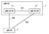
- FIG. 1 is a diagram illustrating a configuration example of a wireless communication network according to a first embodiment.
- 1 is a diagram illustrating a configuration example of a wireless communication network according to a first embodiment.
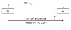
- FIG. 5 is a sequence diagram illustrating an example of signaling between a CU and a DU according to the first embodiment.
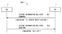
- FIG. 13 is a sequence diagram illustrating an example of signaling between a CU and a DU according to the second embodiment.
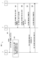
- FIG. 15 is a sequence diagram illustrating an example of signaling for transmitting an updated SI according to the third embodiment. It is a figure showing an example of a format of F1AP message (e.g., ⁇ BWP ⁇ INFORMATION message) concerning a 3rd embodiment.
- FIG. 16 is a sequence diagram illustrating an example of signaling between a CU and a DU according to the fourth embodiment. It is a figure showing an example of a format of F1AP message (e.g., ⁇ UE ⁇ CONTEXT ⁇ MODIFICATION ⁇ REQUIRED message) concerning a 4th embodiment. It is a block diagram showing the example of composition of the central node (e.g., @ gNB-CU) concerning some embodiments.
- FIG. 14 is a block diagram illustrating a configuration example of a distributed node (e.g., gNB-DU) according to some embodiments.
- a plurality of embodiments described below can be implemented independently or can be implemented in appropriate combinations. These embodiments have novel features that are different from each other. Therefore, these embodiments contribute to solving different objects or problems, and contribute to achieving different effects.
- FIG. 5 shows a configuration example of a wireless communication network according to the present embodiment.
- the wireless communication network according to the present embodiment includes a gNB Central Unit (gNB-CU) 1 and one or more gNB Distributed Units (gNB-DUs) 2.
- the gNB-CU1 and each gNB-DU2 are connected by an interface 501.
- the interface 501 is an F1 interface.
- UE3 is connected to at least one gNB-DU2 via at least one air interface 502.
- the gNB-CU 1 may include a Control Plane (CP) Unit (gNB-CU-CP) 11 and one or more User Plane (UP) Units (gNB-CU-UP) 12. Good.
- the gNB-CU-CP 11 is connected to the gNB-CU-UP 12 via the control plane interface 601 (i.e., @ E1 interface).
- the gNB-CU-CP 11 is connected to the gNB-DU2 via the control plane interface 602 (i.e., @ F1-C interface).
- the gNB-CU-UP 12 is connected to the gNB-DU2 via a user plane interface 603 (i.e., @ F1-U interface).
- the gNB-CU 1 may be a logical node that hosts gNB's RRC, SDAP, and PDCP protocols (or gNB's RRC and PDCP protocols).
- the gNB-DU2 may be a logical node that hosts RLC, MAC, and PHY layers of the gNB.
- the gNB-DU2 may determine the BWP set to be set for the UE3, and the gNB-DU2 may notify the related gNB-CU1 of the setting of the BWP set for the UE3.
- the gNB-DU 2 may determine the (first) active @ BWP (s) of the UE 3 and notify this to the related gNB-CU 1.
- gNB-CU1 may determine the BWP set to be set for UE3, and gNB-CU1 may notify the associated gNB-DU2 of the setting of the BWP set for UE3. Additionally or alternatively, the gNB-CU 1 may determine the (first) active @ BWP (s) of the UE 3 and notify the related gNB-DU 2 of this. Note that in any of these cases, the gNB-DU2 may change the active @ BWP (s) of the UE3. That is, gNB-DU2 may determine activation / deactivation of BWP (s). Furthermore, gNB-DU2 may notify gNB-CU1 of the information on the changed BWP (s). The information on the BWP (s) after the change may be, for example, information indicating whether each BWP is activated or deactivated, or information indicating a difference from the information on the BWP (s) before the change. There may be.
- FIG. 7 shows a process 700 that is an example of signaling between the gNB-CU1 and the gNB-DU2.
- gNB-DU2 transmits an F1 Application Protocol message.
- the name of the message is not limited to this, but may be, for example, a BWP INFORMATION message.
- the message includes at least one terminal list (ie, UE list).
- the at least one UE list indicates at least one of the following: (A) UEs for which no Common Search Space (CSS) is set in each active DL BWP; (B) UEs for which at least Search Space (SS) for receiving SI at each active DL BWP is not set; (C) UEs that need to receive updated SI via dedicated signaling for each UE (or UEs that need to transmit updated SI using dedicated signaling for each UE, or gNB-CU1 transmits updated SI for each UE) UEs that need to be transmitted in dedicated signaling of (D) UEs in which each active DL BWP is a non-initial DL BWP; and (e) UEs receiving on each DL BWP.
- C UEs that need to receive updated SI via dedicated signaling for each UE (or UEs that need to transmit updated SI using dedicated signaling for each UE, or gNB-CU1 transmits updated SI for each UE) UEs that need to be transmitted in dedicated signaling
- gNB-CU 1 By receiving a UE list indicating UEs for which active CSS is not set in each active DL DL BWP from gNB-DU2, gNB-CU 1 knows UEs staying in active DL DL BWP where CSS is not set. Can be. This allows, for example, the gNB-CU 1 to determine UEs that need to transmit updated @ SI via dedicated signaling (e.g., $ RRC @ Reconfiguration message). In other words, this allows gNB-DU2 to inform gNB-CU1 of UEs that need to send updated @ SI via dedicated signaling.
- the UE list is useful, for example, for an implementation in which the gNB-DU2 determines whether to set CSS in the non-initial BWP.
- the UE list may be a list of UEs staying in active ⁇ DL ⁇ BWP for which CSS is not set.
- gNB-DU2 selects UEs that have received CSS on active DL BWP for which no CSS has been set from UEs that are RRC_Connected in their own cell, and transmits a list of the selected UEs to gNB-CU1. Is also good.
- gNB-DU2 transmits to gNB-CU1 a list of UEs for which at least Search @ Space (SS) (SI-SS) for receiving at least SI in each active @ DL @ BWP is not set. You may. As a result, the gNB-CU 1 can know the UEs staying in the active ⁇ DL ⁇ BWP for which the SI-SS is not set.
- the SI-SS may be included in the CSS or may be included in the UE ⁇ specific search space ⁇ (USS).
- gNB-CU1 can directly know such UEs. This allows, for example, the gNB-CU 1 to determine UEs that need to transmit updated @ SI via dedicated signaling.
- the UE list is useful, for example, for an implementation in which the gNB-DU2 determines whether to set CSS in the non-initial BWP.
- gNB-DU2 selects UEs that are received in active DL BWP for which CSS is not set from UEs that are RRC_Connected in their own cell, and transmits a list of the selected UEs to gNB-CU1. Good.
- the gNB-CU 1 can know the UEs staying in the non-initial DL ⁇ BWP by receiving the UE list indicating the UEs in which each active ⁇ DL ⁇ BWP is the non-initial DL ⁇ BWP. This allows, for example, the gNB-CU 1 to determine UEs that need to transmit updated @ SI via dedicated signaling.
- the UE list is useful, for example, for an implementation in which the gNB-CU 1 determines whether to set the CSS in the non-initial BWP and instructs the gNB-DU 2 to set the CSS of the non-initial BWP.
- the UE list is also useful for an implementation in which the gNB-DU2 determines whether to set CSS in the non-initial BWP.
- the gNB-CU 1 further refers to other information (eg, ⁇ Cell ⁇ Group ⁇ Configuration ⁇ (CG-Config or CellGroupConfig)) in order to know whether CSS is set in each non-initial BWP. Good.
- the gNB-DU 2 may select UEs that are received with non-initial active DL BWP from UEs that are RRC_Connected in their own cell, and may transmit a list of the selected UEs to the gNB-CU 1.
- the gNB-CU 1 receives the UE list indicating the UEs received on each DL @ BWP (ie, a list of UEs for each DL @ BWP) from the gNB-DU2, so that the gNB-CU 1 can determine the UEs staying in each DL @ BWP ( ie, UEs) whose active DL BWP is each DL BWP.
- This allows, for example, the gNB-CU 1 to determine UEs that need to transmit updated @ SI via dedicated signaling.
- the UE list is useful, for example, for an implementation in which the gNB-DU2 determines whether to set CSS in the non-initial BWP.
- the gNB-CU 1 may further refer to other information (e.g., @ CG-Config or CellGroupConfig) in order to know whether CSS is set in each non-initial BWP.
- the gNB-CU 1 is included in the DU to CU RRC Information information element (Information Element IE) in the F1AP: UE Context Setup Response message received from the gNB-DU 2 during the UE Context Setup procedure.
- Information Element IE Information Element
- UE Context Setup Response message received from the gNB-DU 2 during the UE Context Setup procedure.
- the gNB-DU2 can include information about Common ⁇ Search ⁇ Space in "CellGroupConfig" @IE. Therefore, gNB-CU1 can know whether CSS is set by gNB-DU2 in each non-initial BWP by looking at CellGroupConfig ⁇ IE ⁇ .
- the UE list is useful for an implementation in which the gNB-CU 1 determines whether or not to set the CSS in the non-initial BWP and instructs the gNB-DU 2 to set the CSS of the non-initial BWP.
- UE lists may use arbitrary identifiers for distinguishing UEs.
- the identifier used to distinguish UEs in the UE list is Cell RNTI (C-RNTI), gNB-CU UE F1AP ID, gNB-DU UE F1AP ID, or gNB-CU UE F1AP ID and gNB- It may be a pair of DU UE F1AP ID.
- the C-RNTI uniquely identifies a UE (or an RRC connection of the UE) in a cell for scheduling.
- the gNB-CU ⁇ UE ⁇ F1AP ⁇ ID uniquely identifies a UE association on the F1 interface in the gNB-CU1.
- the gNB-DU UE F1AP ID uniquely identifies a UE association on the F1 interface in gNB-DU2.
- gNB-DU2 responds to receiving the first control message (ie, $ F1AP message) including the system information update notification (System ⁇ Information ⁇ Update ⁇ Notification) from gNB-CU1 as described above.
- a second control message (ie, $ F1AP message) including the UE list may be transmitted to gNB-CU1.
- the system information update notification indicates that the system information is updated in the next modification @ period. This contributes to promptly notifying the gNB-CU 1 from the gNB-DU 2 that there is a UE that requires transmission of the updated SI by dedicated signaling when updating the SI by the gNB-CU 1.
- the system information may be, for example, a Public Warning System (PWS) warning notification (Warning Notification) message, or an Earthquake and Tsunamiami Warning System (ETWS) warning notification message (eg ETWS primary notification, ETWS secondary). notification, or both).
- PWS Public Warning System
- ETWS Earthquake and Tsunamiami Warning System
- the first control message may be a SYSTEM ⁇ INFORMATION ⁇ DELIVERY ⁇ COMMAND message.
- gNB-DU2 In response to receiving the SYSTEM ⁇ INFORMATION ⁇ DELIVERY ⁇ COMMAND message, gNB-DU2 broadcasts the requested system information in CSS. Further, in the present embodiment, gNB-DU2 transmits a second control message including the above-described UE list to gNB-CU1.
- the name of the second control message is not limited to this, but may be, for example, a SYSTEM ⁇ INFORMATION ⁇ DELIVERY ⁇ CONFIRM message.
- FIG. 8 shows a process 800 which is an example of signaling between the gNB-CU1 and the gNB-DU2.
- gNB-CU1 transmits a SYSTEM ⁇ INFORMATION ⁇ DELIVERY ⁇ COMMAND message including a system information update notification to gNB-DU2.
- gNB-DU2 in response to receiving the SYSTEM ⁇ INFORMATION ⁇ DELIVERY ⁇ COMMAND message, gNB-DU2 transmits a SYSTEM ⁇ INFORMATION ⁇ DELIVERY ⁇ CONFIRM message including the above UE list to gNB-CU1.
- the gNB-DU 2 may transmit the above-described UE list to the gNB-CU 1 in response to the determination of updating the system information by itself. This contributes to promptly notifying the gNB-CU 1 from the gNB-DU 2 that there is a UE that requires transmission of the updated SI by dedicated signaling when updating the SI by the gNB-DU 2.
- the gNB-DU 2 may transmit the above-described UE list to the gNB-CU 1 in response to receiving the request for the UE list from the gNB-CU 1. This allows the gNB-CU 1 to know at any time (at a given time) that there are UEs that require transmission of the updated SI by dedicated signaling.
- the gNB-DU2 is configured to transmit at least one UE list to the gNB-CU1.
- the at least one UE list indicates at least one of the following: (A) UEs for which no Common Search Space (CSS) is set in each active DL BWP; (B) UEs for which at least Search Space (SS) for receiving SI at each active DL BWP is not set; (C) UEs that need to receive updated SI via dedicated signaling for each UE (or UEs that need to transmit updated SI by dedicated signaling for each UE, or gNB-CU 1 transmits updated SI for each UE) UEs that need to be transmitted in dedicated signaling); (D) UEs in which each active DL BWP is a non-initial DL BWP; and (e) UEs receiving on each DL BWP.
- C Common Search Space
- SS Search Space
- dedicated signaling eg, RRC Reconfiguration message
- FIG. 9 shows a procedure 900 that is an example of signaling for the transmission of an updated SI.
- gNB-DU2 instructs UE3 via PDCCH (i.e., DCI) to change active ⁇ DL ⁇ BWP to non-initial DL ⁇ BWP for which Common ⁇ Search ⁇ Space (CSS) is not set.
- PDCCH i.e., DCI
- the UE 3 operates to stay at the non-initial DL @ BWP in which the CSS is not set and to receive a signal at the non-initial DL @ BWP.
- Steps 903 and 904 are the same as steps 801 and 802 shown in FIG. That is, in step 903, the gNB-CU1 transmits a SYSTEM ⁇ INFORMATION ⁇ DELIVERY ⁇ COMMAND message including a system information update notification to the gNB-DU2. In Step 904, in response to receiving the SYSTEM ⁇ INFORMATION ⁇ DELIVERY ⁇ COMMAND message, gNB-DU2 transmits a SYSTEM ⁇ INFORMATION ⁇ DELIVERY ⁇ CONFIRM message including the UE list described in the first embodiment to gNB-CU1.
- the gNB-CU 1 transmits the updated SI to one or more UEs 3 via dedicated signaling (e.g., ⁇ RRC ⁇ Reconfiguration message) for each UE.
- dedicated signaling e.g., ⁇ RRC ⁇ Reconfiguration message
- the gNB-CU 1 needs to know the UEs staying in the active DL DL BWP for which the CSS has not been set by referring to the received UE list, and need to transmit updated SI through dedicated signaling. Is determined.
- the RRC @ Reconfiguration message containing the updated SI is carried from gNB-CU1 to gNB-DU2 on the F1 interface by a DL @ RRC @ MESSAGE @ TRANSFER message, and transmitted to UE3 by gNB-DU2.
- step 906 UE3 transmits an RRC ⁇ Reconfiguration ⁇ Complete message to gNB-CU1.
- the RRC ⁇ Reconfiguration ⁇ Complete message is carried from gNB-DU2 to gNB-CU1 on the F1 interface by a UL ⁇ RRC ⁇ MESSAGE ⁇ TRANSFER message.
- gNB-CU 1 can determine UEs staying in active DL BWP for which CSS is not set, and update SIs of these UEs via dedicated signaling. Can be sent.
- ⁇ Third embodiment> This embodiment provides details on the F1AP message for carrying the UE list described in the first embodiment.
- the configuration example of the wireless communication network according to the present embodiment is the same as the example shown in FIGS.
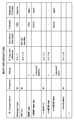
- FIG. 10 shows an example of the format of an F1AP message (e.g., ⁇ BWP ⁇ INFORMATION message) for carrying the UE list described in the first embodiment.
- the message shown in FIG. 10 is transmitted to gNB-CU1 by gNB-DU2.
- the F1AP message (e.g., ⁇ BWP ⁇ INFORMATION message) shown in FIG. 10 includes a BWP list indicating all (DL) ⁇ BWPs.
- the BWP list includes (DL) UE list for each BWP (or UE ID list).
- the UE list uses C-RNTI to distinguish UEs.
- the UE list (or UE @ ID list) may use another identifier (e.g., ⁇ gNB-CU ⁇ UE @ F1AP @ ID ⁇ or gNB-DU @ UE @ F1AP @ ID) instead of C-RNTI.
- the F1AP message shown in FIG. 10 enables the gNB-DU2 to provide the gNB-CU1 with a UE list (ie, a list of UEs for each DL @ BWP) indicating UEs received on each DL @ BWP. I do.
- a UE list ie, a list of UEs for each DL @ BWP
- the configuration example of the wireless communication network according to the present embodiment is the same as the example shown in FIGS.
- the example has been described in which the gNB-DU2 provides the UE list to the gNB-CU1.
- These examples described in the first to third embodiments use a non-UE associated procedure or signaling for transmitting the UE list from the gNB-DU2 to the gNB-CU1. Used. Therefore, the first to third embodiments can reduce the number of signaling between gNB-CU1 and gNB-DU2 as compared to a method using a procedure or signaling (UE associated procedure or signaling) associated with the UE.
- UE associated procedure or signaling UE associated procedure or signaling
- the gNB-DU 2 may notify the gNB-CU 1 of the change in the active DL DL BWP of the UE 3 using a procedure or signaling associated with the UE.
- the gNB-DU2 sends a message indicating a change in active @ DL @ BWP of the UE3 to the gNB-CU1.
- the gNB-DU2 may transmit a message indicating the change of the active @ DL @ BWP of the UE3 to the gNB-CU1 in response to the change of the active @ DL @ BWP of the UE3.
- the gNB-DU2 may send a message indicating the change of the active @ DL @ BWP of the UE3 to the gNB-CU1 after the change of the active @ DL @ BWP of the UE3.
- the gNB-DU 2 may notify the gNB-CU 1 that the active DL BWP of the UE 3 has been changed from the initial BWP to a non-initial DL BWP (particularly, a non-initial DL BWP having no CSS).
- gNB-CU1 can know UEs staying in active ⁇ DL ⁇ BWP for which CSS is not set. This allows, for example, the gNB-CU 1 to determine UEs that need to transmit updated @ SI via dedicated signaling.
- the gNB-DU2 when the gNB-DU2 changes the active DL BWP of the UE3 (change or switch), the gNB-DU2 changes the active DL BWP of the UE3 in the UE Context Modification Required procedure started by the gNB-DU2. or a message including an information element indicating “switching” may be transmitted to the gNB-CU1.
- gNB-DU2 responds to the change of active DL BWP of UE3 from initial BWP to non-initial DL BWP (particularly, non-initial DL BWP without CSS), and transmits a message including the information element. You may transmit to gNB-CU1.
- gNB-DU2 may include the information element in the F1AP: ⁇ UE ⁇ CONTEXT ⁇ MODIFICATION ⁇ REQUIRED message.
- the information element may be a BOOLEAN data type variable indicating whether the active DL DL BWP of the UE 3 has been changed from the initial DL DL BWP to the non-initial DL DL BWP. Instead, the information element may be an ENUMERATED type variable indicating that active ⁇ DL ⁇ BWP of UE3 has no CSS. Instead, the information element may be an INTEGER type variable indicating the identifier (e.g., ⁇ BWP ⁇ ID) of active ⁇ DL ⁇ BWP of UE3.
- FIG. 11 shows a procedure 1100 which is an example of signaling according to the present embodiment.
- gNB-DU2 transmits a UE ⁇ CONTEXT ⁇ MODIFICATION ⁇ REQUIRED message.
- the message includes the information elements described in the present embodiment.
- FIG. 12 shows an example of the format of an F1 message including the information elements described in the present embodiment.
- the UE ⁇ CONTEXT ⁇ MODIFICATION ⁇ REQUIRED message shown in FIG. 12 is transmitted by the gNB-DU2 to the gNB-CU1 to request a modification of the UE ⁇ context.
- the UE ⁇ CONTEXT ⁇ MODIFICATION ⁇ REQUIRED message shown in FIG. 12 includes a UE ⁇ switch ⁇ to ⁇ BWP information element (IE).
- IE BWP information element
- the “UE switch to BWP” IE may be a BOOLEAN data type variable indicating whether or not the active DL DL BWP of the UE 3 has been changed from DL DL BWP to non-initial DL DL BWP.
- “UE ⁇ switch ⁇ to ⁇ BWP” ⁇ IE may be an ENUMERATED type variable indicating that active ⁇ DL ⁇ BWP of UE3 has no CSS.
- the UE ⁇ CONTEXT ⁇ MODIFICATION ⁇ REQUIRED message in Fig. 12 may include a BWP-ID information element (IE) instead of "UE ⁇ switch ⁇ to ⁇ BWP" ⁇ IE.
- the “BWP-ID” IE may be an INTEGER variable indicating the identifier (e.g., ⁇ BWP ⁇ ID) of active ⁇ DL ⁇ BWP of UE3.
- FIG. 13 is a block diagram illustrating a configuration example of the gNB-CU 1 according to the above embodiment.
- the configurations of gNB-CU-CP11 and gNB-CU-UP12 may be the same as those shown in FIG.
- gNB-CU1 includes a network interface 1301, a processor 1302, and a memory 1303.
- the network interface 1301 is used to communicate with network nodes (e.g., @ gNB-DU2 and control plane (CP) node and user plane (UP) node in 5GC).
- the network interface 1301 may include a plurality of interfaces.
- the network interface 1301 may include, for example, an optical fiber interface for CU-DU communication and a network interface compliant with IEEE ⁇ 802.3 ⁇ series.
- the processor 1302 performs digital baseband signal processing (data plane processing) and control plane processing for wireless communication.
- Processor 1302 may include multiple processors.
- the processor 1302 includes a modem processor (eg, Digital Signal Processor (DSP)) that performs digital baseband signal processing and a protocol stack processor (eg, Central Processing Unit (CPU) or Micro Processing Unit (CPU) that performs control plane processing. MPU)).
- DSP Digital Signal Processor
- MPU Micro Processing Unit
- the memory 1303 is configured by a combination of a volatile memory and a nonvolatile memory.
- the volatile memory is, for example, a static random access memory (SRAM) or a dynamic random access memory (DRAM) or a combination thereof.
- the non-volatile memory is a mask Read Only Memory (MROM), an Electrically Erasable Programmable ROM (EEPROM), a flash memory, a hard disk drive, or any combination thereof.
- Memory 1303 may include storage located away from processor 1302. In this case, the processor 1302 may access the memory 1303 via the network interface 1301 or an I / O interface (not shown).
- the memory 1303 may store one or more software modules (computer programs) 1304 including a group of instructions and data for performing processing by the gNB-CU 1 described in the above embodiments.
- the processor 1302 may be configured to read and execute the one or more software modules 1304 from the memory 1303 to perform the processing of the gNB-CU 1 described in the above embodiments. Good.
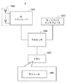
- FIG. 14 is a block diagram illustrating a configuration example of the gNB-DU2 according to the above embodiment.
- the gNB-DU2 includes a Radio @ Frequency transceiver 1401, a network interface 1403, a processor 1404, and a memory 1405.
- the RF transceiver 1401 performs analog RF signal processing to communicate with NG @ UEs.
- RF transceiver 1401 may include multiple transceivers.
- RF transceiver 1401 is coupled to antenna array 1402 and processor 1404.
- the RF transceiver 1401 receives the modulation symbol data from the processor 1404, generates a transmission RF signal, and supplies the transmission RF signal to the antenna array 1402.
- RF transceiver 1401 generates a baseband reception signal based on the reception RF signal received by the antenna array 1402, and supplies this to the processor 1404.
- RF transceiver 1401 may include an analog beamformer circuit for beamforming.
- the analog beamformer circuit includes, for example, a plurality of phase shifters and a plurality of power amplifiers.
- the network interface 1403 is used to communicate with network nodes (e.g., gNB-CU1, gNB-CU-CP11, gNB-CU-UP12).
- Network interface 1403 may include a plurality of interfaces.
- the network interface 1403 may include, for example, at least one of an optical fiber interface for CU-DU communication and a network interface conforming to IEEE ⁇ 802.3 ⁇ series.
- the processor 1404 performs digital baseband signal processing (data plane processing) and control plane processing for wireless communication.
- Processor 1404 may include multiple processors.
- the processor 1404 may include a modem processor (e.g., $ DSP) that performs digital baseband signal processing and a protocol stack processor (e.g., $ CPU or MPU) that performs control plane processing.
- Processor 1404 may include a digital beamformer module for beamforming.
- the digital beamformer module may include a Multiple Input Multiple Output (MIMO) encoder and precoder.
- MIMO Multiple Input Multiple Output
- the memory 1405 is configured by a combination of a volatile memory and a nonvolatile memory.
- the volatile memory is, for example, an SRAM or a DRAM or a combination thereof.
- the non-volatile memory is an MROM, an EEPROM, a flash memory, or a hard disk drive, or any combination thereof.
- the memory 1405 may include storage located away from the processor 1404. In this case, the processor 1404 may access the memory 1405 via the network interface 1403 or an I / O interface (not shown).
- the memory 1405 may store one or more software modules (computer programs) 1406 including instructions and data for performing the processing by the gNB-DU2 described in the above embodiments.
- the processor 1404 may be configured to read and execute the one or more software modules 1406 from the memory 1405 to perform the processing of the gNB-DU2 described in the above embodiments. Good.
- each of the processors included in the gNB-CU1 and the gNB-DU2 according to the above-described embodiment includes a group of instructions for causing a computer to execute the algorithm described with reference to the drawings. And one or more programs including This program can be stored using various types of non-transitory computer readable media and supplied to a computer.
- Non-transitory computer readable media include various types of tangible storage media.
- non-transitory computer-readable media are magnetic recording media (eg, flexible disk, magnetic tape, hard disk drive), magneto-optical recording media (eg, magneto-optical disk), Compact Disc Read Only Memory (CD-ROM), CD-ROM R, CD-R / W, and semiconductor memory (for example, a mask ROM, a programmable ROM (PROM), an Erasable PROM (EPROM), a flash ROM, and a random access memory (RAM)).
- the program may be supplied to the computer by various types of transitory computer readable media. Examples of transitory computer readable media include electrical signals, optical signals, and electromagnetic waves. Transitory computer readable media can provide the program to a computer via a wired communication line such as an electric wire and an optical fiber, or a wireless communication line.
- gNB-CU 1 uses the UE list received from the gNB-DU 2 to determine UEs that need to transmit updated SI via dedicated signaling.
- gNB-CU1 may use the UE list received from gNB-DU2 for another purpose.
- the signaling between gNB-CU1 and gNB-DU2 described in the above embodiment may be performed between gNB-CU-CP11 and gNB-DU2.
- the at least one terminal list includes: A plurality of wireless terminals for which no Common Search Space is set in each activated downlink Bandwidth Part (BWP); A plurality of wireless terminals for which at least a search space (SS) for receiving system information is not set in each activated downlink BWP; A plurality of wireless terminals that need to receive updated system information via individual signaling for each wireless terminal; A plurality of wireless terminals, each activated downlink BWP being a non-initial downlink BWP; and a plurality of wireless terminals receiving on each downlink BWP; Indicating at least one of Distributed unit.
- BWP Bandwidth Part
- SS search space
- the at least one processor is configured to transmit the at least one terminal list to the central unit in response to receiving a first control message including a system information update notification from the central unit.
- the dispersing unit according to supplementary note 1.
- the first control message is a SYSTEM INFORMATION DELIVERY COMMAND message, The dispersing unit according to supplementary note 2.
- the at least one processor is configured to transmit the at least one terminal list to the central unit in response to determining to update system information; 4.
- the dispersion unit according to any one of supplementary notes 1 to 3.
- the at least one processor is configured to transmit the at least one terminal list to the central unit in response to receiving a request from the central unit; 5.
- the dispersion unit according to any one of supplementary notes 1 to 4.
- the at least one terminal list indicates a plurality of wireless terminals for which no Common Search Space is set in each activated downlink BWP, 6.
- the dispersion unit according to any one of supplementary notes 1 to 5.
- the at least one terminal list indicates a plurality of wireless terminals that have not been configured with a Search Space (SS) for receiving at least system information in each activated downlink BWP.
- SS Search Space
- the dispersion unit according to any one of supplementary notes 1 to 5.
- the at least one terminal list indicates a plurality of wireless terminals, each activated downlink BWP being a non-initial downlink BWP, 6.
- the dispersion unit according to any one of supplementary notes 1 to 5.
- the at least one terminal list includes a terminal list for each BWP for indicating a plurality of wireless terminals that are receiving on each downlink BWP, 6.
- the dispersion unit according to any one of supplementary notes 1 to 5.
- the central unit of the base station At least one memory; At least one processor coupled to the at least one memory; With The at least one processor is configured to receive at least one terminal list from a distribution unit of the base station;
- the at least one terminal list includes: A plurality of wireless terminals for which no Common Search Space (CSS) is set in each activated downlink Bandwidth Part (BWP); A plurality of wireless terminals for which at least a search space (SS) for receiving system information is not set in each activated downlink BWP; A plurality of wireless terminals that need to receive updated system information via individual signaling for each wireless terminal; A plurality of wireless terminals, each activated downlink BWP being a non-initial downlink BWP; and a plurality of wireless terminals receiving on each downlink BWP; Indicating at least one of Central unit.
- SCS Common Search Space
- SS search space
- the at least one processor is configured to send a first control message including a system information update notification to the distribution unit;
- the first control message causes the distribution unit to send the at least one terminal list to the central unit;
- the central unit according to attachment 10.
- the first control message is a SYSTEM INFORMATION DELIVERY COMMAND message, A central unit according to attachment 11.
- the at least one processor is configured to send a request for the at least one terminal list to the distribution unit; 13.
- the central unit according to any one of supplementary notes 10 to 12.
- the at least one processor is configured to, after receiving the at least one terminal list, transmit updated system information to one or more wireless terminals via individual signaling for each wireless terminal; 14.
- the central unit according to any one of supplementary notes 10 to 13.
- the at least one terminal list indicates a plurality of wireless terminals for which a Common Search Space (CSS) has not been set in each activated downlink BWP. 15.
- the central unit according to any one of supplementary notes 10 to 14.
- the at least one terminal list indicates a plurality of wireless terminals that have not been configured with a Search Space (SS) for receiving at least system information in each activated downlink BWP.
- SS Search Space
- the central unit according to any one of supplementary notes 10 to 14.
- the at least one terminal list indicates a plurality of wireless terminals, each activated downlink BWP being a non-initial downlink BWP, 15.
- the central unit according to any one of supplementary notes 10 to 14.
- the at least one terminal list includes a terminal list for each BWP for indicating a plurality of wireless terminals that are receiving on each downlink BWP, 15.
- the central unit according to any one of supplementary notes 10 to 14.
- the at least one terminal list includes: A plurality of wireless terminals for which no Common Search Space (CSS) is set in each activated downlink Bandwidth Part (BWP); A plurality of wireless terminals for which at least a search space (SS) for receiving system information is not set in each activated downlink BWP; A plurality of wireless terminals that need to receive updated system information via individual signaling for each wireless terminal; A plurality of wireless terminals, each activated downlink BWP being a non-initial downlink BWP; and a plurality of wireless terminals receiving on each downlink BWP; Indicating at least one of Method.
- CSS Common Search Space
- SS search space
- (Appendix 20) A method in a central unit of a base station, Receiving at least one terminal list from a distribution unit of the base station;
- the at least one terminal list includes: A plurality of wireless terminals for which no Common Search Space is set in each activated downlink Bandwidth Part (BWP); A plurality of wireless terminals for which at least a search space (SS) for receiving system information is not set in each activated downlink BWP; A plurality of wireless terminals that need to receive updated system information via individual signaling for each wireless terminal;
- a program for causing a computer to perform a method in a distributed unit of a base station comprises transmitting at least one terminal list to a central unit of the base station;
- the at least one terminal list includes: A plurality of wireless terminals for which no Common Search Space is set in each activated downlink Bandwidth Part (BWP); A plurality of wireless terminals for which at least a search space (SS) for receiving system information is not set in each activated downlink BWP; A plurality of wireless terminals that need to receive updated system information via individual signaling for each wireless terminal;
- a plurality of wireless terminals, each activated downlink BWP being a non-initial downlink BWP; and a plurality of wireless terminals receiving on each downlink BWP; Indicating at least one of program.
- a program for causing a computer to perform a method in a central unit of a base station comprises receiving at least one terminal list from a distribution unit of the base station;
- the at least one terminal list includes: A plurality of wireless terminals for which no Common Search Space is set in each activated downlink Bandwidth Part (BWP); A plurality of wireless terminals for which at least a search space (SS) for receiving system information is not set in each activated downlink BWP; A plurality of wireless terminals that need to receive updated system information via individual signaling for each wireless terminal;
- a distributed unit of a base station At least one memory; At least one processor coupled to the at least one memory; With The at least one processor is configured to send a message to a central unit of the base station, the message including an information element indicating a change in an activated downlink Bandwidth Part (BWP) of a wireless terminal.
- BWP Bandwidth Part
- the at least one processor is configured to transmit the message to a central unit of the base station in response to a change in an activated downlink BWP of the wireless terminal.
- the information element indicates whether the activation downlink BWP of the wireless terminal has been changed from an initial downlink BWP to a non-initial downlink BWP, 23.
- the information element indicates that the activation downlink BWP of the wireless terminal does not have a Common Search Space, 23.
- the information element indicates an identifier of the activated downlink BW after the change of the wireless terminal, 23.
- the central unit of the base station At least one memory; At least one processor coupled to the at least one memory; With The at least one processor is configured to receive a message from a distribution unit of the base station, the message including an information element indicating a change in an activated downlink BWP of a wireless terminal.
- Central unit The central unit of the base station, At least one memory; At least one processor coupled to the at least one memory; With The at least one processor is configured to receive a message from a distribution unit of the base station, the message including an information element indicating a change in an activated downlink BWP of a wireless terminal.
- Central unit Central unit.
- the information element indicates whether the activation downlink BWP of the wireless terminal has been changed from an initial downlink BWP to a non-initial downlink BWP, A central unit according to attachment 28.
- the information element indicates that the activation downlink BWP of the wireless terminal does not have a Common Search Space, A central unit according to attachment 28.
- the information element indicates an identifier of the activated downlink BW after the change of the wireless terminal, A central unit according to attachment 28.
- the at least one processor is configured to, after receiving the information element, transmit updated system information to the wireless terminal via dedicated signaling for each wireless terminal.
- the central unit according to any one of Supplementary Notes 28 to 31.
Landscapes
- Engineering & Computer Science (AREA)
- Computer Networks & Wireless Communication (AREA)
- Signal Processing (AREA)
- Power Engineering (AREA)
- Mobile Radio Communication Systems (AREA)
Priority Applications (6)
| Application Number | Priority Date | Filing Date | Title |
|---|---|---|---|
| JP2020536460A JP7078119B2 (ja) | 2018-08-09 | 2019-07-25 | gNBの分散ユニットにおける方法、gNBの中央ユニットにおける方法、及びgNBの方法 |
| CN202411722290.0A CN119766283A (zh) | 2018-08-09 | 2019-07-25 | 分布式单元、中央单元及基站所用的方法 |
| CN201980052740.0A CN112602361B (zh) | 2018-08-09 | 2019-07-25 | 分布式单元、中央单元及其方法 |
| EP19847022.1A EP3836683A4 (de) | 2018-08-09 | 2019-07-25 | Verteilungseinheit, zentraleinheit und verfahren dafür |
| JP2022080265A JP7260035B2 (ja) | 2018-08-09 | 2022-05-16 | 中央ユニットにおける方法、分散ユニットにおける方法、及び基地局の方法 |
| JP2023062057A JP7683624B2 (ja) | 2018-08-09 | 2023-04-06 | 中央ユニット、分散ユニット、基地局、及びこれらの方法 |
Applications Claiming Priority (2)
| Application Number | Priority Date | Filing Date | Title |
|---|---|---|---|
| JP2018-150709 | 2018-08-09 | ||
| JP2018150709 | 2018-08-09 |
Publications (1)
| Publication Number | Publication Date |
|---|---|
| WO2020031728A1 true WO2020031728A1 (ja) | 2020-02-13 |
Family
ID=69407219
Family Applications (1)
| Application Number | Title | Priority Date | Filing Date |
|---|---|---|---|
| PCT/JP2019/029283 Ceased WO2020031728A1 (ja) | 2018-08-09 | 2019-07-25 | 分散ユニット、中央ユニット、及びこれらの方法 |
Country Status (5)
| Country | Link |
|---|---|
| US (3) | US11516875B2 (de) |
| EP (1) | EP3836683A4 (de) |
| JP (3) | JP7078119B2 (de) |
| CN (2) | CN119766283A (de) |
| WO (1) | WO2020031728A1 (de) |
Cited By (1)
| Publication number | Priority date | Publication date | Assignee | Title |
|---|---|---|---|---|
| JP2022145872A (ja) * | 2018-09-07 | 2022-10-04 | 日本電気株式会社 | 基地局の分散ユニット及びその方法 |
Families Citing this family (7)
| Publication number | Priority date | Publication date | Assignee | Title |
|---|---|---|---|---|
| US11516875B2 (en) * | 2018-08-09 | 2022-11-29 | Nec Corporation | Distributed unit, central unit, and method therefor |
| US11206595B2 (en) * | 2019-08-14 | 2021-12-21 | Qualcomm Incorporated | Systems and methods for handover of 5G location sessions for an NG-RAN location management component |
| KR102932122B1 (ko) | 2020-05-19 | 2026-02-26 | 텔레폰악티에볼라겟엘엠에릭슨(펍) | 주파수 대역 선택 및 측정 구성의 관리 |
| US20240080221A1 (en) * | 2021-02-10 | 2024-03-07 | Telefonaktiebolaget Lm Ericsson (Publ) | Fifth generation (5g) hybrid data over cable service interface specification (docsis) 5g new radio (nr) system |
| US11464068B1 (en) * | 2021-02-25 | 2022-10-04 | Sprint Spectrum L.P. | Selection of access node to serve a device, with the selection being based on RRC connection establishment failure history as to at least one other device |
| CN117560745A (zh) * | 2022-08-02 | 2024-02-13 | 大唐移动通信设备有限公司 | 一种通信传输处理方法、装置及通信设备 |
| US12302450B2 (en) * | 2022-10-05 | 2025-05-13 | Radisys Corporation | Coordinated PWS warning delivery in 5G networks |
Citations (1)
| Publication number | Priority date | Publication date | Assignee | Title |
|---|---|---|---|---|
| JP2018150709A (ja) | 2017-03-13 | 2018-09-27 | 三井住友建設株式会社 | 着脱式間仕切り壁 |
Family Cites Families (9)
| Publication number | Priority date | Publication date | Assignee | Title |
|---|---|---|---|---|
| EP3482602B1 (de) * | 2016-07-05 | 2023-10-18 | Apple Inc. | Systeme, verfahren und vorrichtungen zur trennung einer steuerungsbenutzerebene für 5g-funkzugangsnetzwerke |
| US10485000B2 (en) * | 2016-09-28 | 2019-11-19 | Sharp Kabushiki Kaisha | User equipment, base stations and methods |
| WO2018084669A1 (en) * | 2016-11-04 | 2018-05-11 | Samsung Electronics Co., Ltd. | Method and user equipment for provisioning minimum system information in wireless communication system |
| KR102114096B1 (ko) * | 2017-01-06 | 2020-05-25 | 주식회사 케이티 | 차세대 무선망에서 하향 링크 제어 채널을 송수신하는 방법 및 그 장치 |
| US10660065B2 (en) * | 2017-04-13 | 2020-05-19 | Lg Electronics Inc. | Method for transmitting a paging message and device supporting the same |
| EP3479647B1 (de) * | 2017-05-05 | 2020-12-02 | Samsung Electronics Co., Ltd. | Verfahren zur einrichtung einer fronthaul-schnittstelle und basisstation |
| AU2018314077B2 (en) * | 2017-08-10 | 2023-02-02 | Samsung Electronics Co., Ltd. | Apparatus and method of system information transmission and reception on a carrier supporting multiple bandwidth parts |
| EP3534651A1 (de) * | 2018-02-15 | 2019-09-04 | Comcast Cable Communications, LLC | Drahtlose kommunikation mit verwendung von drahtlosvorrichtungsinformationen |
| US11516875B2 (en) * | 2018-08-09 | 2022-11-29 | Nec Corporation | Distributed unit, central unit, and method therefor |
-
2019
- 2019-02-15 US US16/277,322 patent/US11516875B2/en active Active
- 2019-07-25 WO PCT/JP2019/029283 patent/WO2020031728A1/ja not_active Ceased
- 2019-07-25 CN CN202411722290.0A patent/CN119766283A/zh active Pending
- 2019-07-25 JP JP2020536460A patent/JP7078119B2/ja active Active
- 2019-07-25 CN CN201980052740.0A patent/CN112602361B/zh active Active
- 2019-07-25 EP EP19847022.1A patent/EP3836683A4/de active Pending
-
2022
- 2022-05-16 JP JP2022080265A patent/JP7260035B2/ja active Active
- 2022-11-22 US US17/992,357 patent/US20230077825A1/en not_active Abandoned
-
2023
- 2023-04-06 JP JP2023062057A patent/JP7683624B2/ja active Active
-
2024
- 2024-01-12 US US18/411,272 patent/US20240155727A1/en active Pending
Patent Citations (1)
| Publication number | Priority date | Publication date | Assignee | Title |
|---|---|---|---|---|
| JP2018150709A (ja) | 2017-03-13 | 2018-09-27 | 三井住友建設株式会社 | 着脱式間仕切り壁 |
Non-Patent Citations (4)
| Title |
|---|
| "3rd Generation Partnership Project; Technical Specification Group Radio Access Network; NG-RAN; Architecture description (Release 15", 3GPP TS 38.401, June 2018 (2018-06-01) |
| CATT: "CSS configuration for SI acquisition in non- initial BWP [C077]", 3GPP TSG RAN WG2 ADHOC_2018_07_NR R2-1810493, 22 June 2018 (2018-06-22), XP051467654 * |
| NEC: "I mpact to F1 for SI reception in Connected mode", 3GPP TSG RAN WG2 #102 R2-1808252, 11 May 2018 (2018-05-11), XP051444543 * |
| R2-1810493, 3GPP TSG-RAN WG2 MEETING #AH-1807, MONTREAL, CANADA, 2 July 2016 (2016-07-02) |
Cited By (3)
| Publication number | Priority date | Publication date | Assignee | Title |
|---|---|---|---|---|
| JP2022145872A (ja) * | 2018-09-07 | 2022-10-04 | 日本電気株式会社 | 基地局の分散ユニット及びその方法 |
| JP7371737B2 (ja) | 2018-09-07 | 2023-10-31 | 日本電気株式会社 | 基地局の分散ユニット及びその方法 |
| US12035333B2 (en) | 2018-09-07 | 2024-07-09 | Nec Corporation | Distributed unit, radio terminal, and methods therefor |
Also Published As
| Publication number | Publication date |
|---|---|
| JP2022097757A (ja) | 2022-06-30 |
| US20200053817A1 (en) | 2020-02-13 |
| US20230077825A1 (en) | 2023-03-16 |
| JP7078119B2 (ja) | 2022-05-31 |
| JP7683624B2 (ja) | 2025-05-27 |
| CN112602361A (zh) | 2021-04-02 |
| CN112602361B (zh) | 2024-12-13 |
| EP3836683A4 (de) | 2022-01-05 |
| EP3836683A1 (de) | 2021-06-16 |
| JP2023076675A (ja) | 2023-06-01 |
| JP7260035B2 (ja) | 2023-04-18 |
| US20240155727A1 (en) | 2024-05-09 |
| JPWO2020031728A1 (ja) | 2021-08-02 |
| CN119766283A (zh) | 2025-04-04 |
| US11516875B2 (en) | 2022-11-29 |
Similar Documents
| Publication | Publication Date | Title |
|---|---|---|
| JP7338748B2 (ja) | ソース基地局、ターゲット基地局、及びこれらの方法 | |
| JP7683624B2 (ja) | 中央ユニット、分散ユニット、基地局、及びこれらの方法 | |
| JP7574905B2 (ja) | 端末装置及びその方法 | |
| CN112005595B (zh) | 无线通信系统中的用户设备及其方法 | |
| JP7371737B2 (ja) | 基地局の分散ユニット及びその方法 | |
| EP3876631B1 (de) | Verteilungseinheit, zentraleinheit und verfahren dafür | |
| WO2019244609A1 (ja) | 端末装置、基地局装置、方法、および、集積回路 |
Legal Events
| Date | Code | Title | Description |
|---|---|---|---|
| 121 | Ep: the epo has been informed by wipo that ep was designated in this application |
Ref document number: 19847022 Country of ref document: EP Kind code of ref document: A1 |
|
| ENP | Entry into the national phase |
Ref document number: 2020536460 Country of ref document: JP Kind code of ref document: A |
|
| NENP | Non-entry into the national phase |
Ref country code: DE |
|
| ENP | Entry into the national phase |
Ref document number: 2019847022 Country of ref document: EP Effective date: 20210309 |