WO2020031757A1 - Dispositif terminal, et procédé - Google Patents
Dispositif terminal, et procédé Download PDFInfo
- Publication number
- WO2020031757A1 WO2020031757A1 PCT/JP2019/029484 JP2019029484W WO2020031757A1 WO 2020031757 A1 WO2020031757 A1 WO 2020031757A1 JP 2019029484 W JP2019029484 W JP 2019029484W WO 2020031757 A1 WO2020031757 A1 WO 2020031757A1
- Authority
- WO
- WIPO (PCT)
- Prior art keywords
- value
- random access
- terminal device
- pdcch
- preamble
- Prior art date
- Legal status (The legal status is an assumption and is not a legal conclusion. Google has not performed a legal analysis and makes no representation as to the accuracy of the status listed.)
- Ceased
Links
Images




Classifications
-
- H—ELECTRICITY
- H04—ELECTRIC COMMUNICATION TECHNIQUE
- H04W—WIRELESS COMMUNICATION NETWORKS
- H04W16/00—Network planning, e.g. coverage or traffic planning tools; Network deployment, e.g. resource partitioning or cells structures
- H04W16/14—Spectrum sharing arrangements between different networks
-
- H—ELECTRICITY
- H04—ELECTRIC COMMUNICATION TECHNIQUE
- H04W—WIRELESS COMMUNICATION NETWORKS
- H04W72/00—Local resource management
- H04W72/50—Allocation or scheduling criteria for wireless resources
- H04W72/54—Allocation or scheduling criteria for wireless resources based on quality criteria
-
- H—ELECTRICITY
- H04—ELECTRIC COMMUNICATION TECHNIQUE
- H04W—WIRELESS COMMUNICATION NETWORKS
- H04W74/00—Wireless channel access
- H04W74/08—Non-scheduled access, e.g. ALOHA
Definitions
- the present invention relates to a terminal device and a method.
- Priority is claimed on Japanese Patent Application No. 2018-151353, filed on August 10, 2018, the content of which is incorporated herein by reference.
- LTE Long Term Evolution
- EUTRA Evolved Universal Terrestrial Radio Access
- 3GPP Third Generation Partnership Project
- a base station apparatus may be referred to as an eNodeB (evolved NodeB), and a terminal apparatus may be referred to as a UE (User Equipment).
- LTE is a cellular communication system in which a plurality of areas covered by a base station device are arranged in a cell shape.
- One base station device may manage a plurality of serving cells.
- next-generation wireless communication standards (NR: ⁇ New ⁇ Radio) are examined in order to propose to IMT (International Mobile Telecommunication) -2020, which is a standard for next-generation mobile communication systems formulated by the International Telecommunication Union (ITU).
- ITU International Telecommunication Union
- Non-Patent Document 1 The NR is required to satisfy the requirements assuming three scenarios of eMBB (enhanced Mobile Broadband), mMTC (massive Machine Type Communication), and URLLC (Ultra Reliable and Low Latency Communication) in the framework of a single technology. I have.
- NR-U NR-Unlicensed
- NR-U NR-Unlicensed
- NR-U NR-Unlicensed
- One embodiment of the present invention provides a terminal device for performing efficient communication and a method used for the terminal device.
- a first aspect of the present invention is a terminal device, in a random access procedure, transmitting a random access preamble and monitoring a corresponding random access response (RAR), and receiving the RAR.
- a MAC (Medium Access Control) layer processing unit that increments a value of a preamble transmission counter for counting the number of times of transmission of the random access preamble when it is determined that the transmission and reception of the random access preamble is not successful.
- a CCA Carrier Assessment
- the N init said in the N before init is set, is determined based on the value of CW is set to at least the random access preamble (Contention Window) (CW size) , the value of the CW, the value of the preamble transmission counter is incremented Updated when done.
- CW size the random access preamble
- the second aspect of the present invention is the terminal device according to the first aspect, wherein in the random access procedure, the RAR is successfully received, and a PUSCH (Msg3) corresponding to the RAR is transmitted.
- a collision resolution message (Msg4) corresponding to the Msg3 is monitored, and when it is considered that the reception of the Msg4 is not successful in the NR-U carrier, the value of the preamble transmission counter is incremented, and the value of the CW is incremented. To update.
- a third aspect of the present invention is a method used in a terminal device, in a random access procedure, transmitting a random access preamble, monitoring a corresponding random access response (RAR), and receiving the RAR. If it is determined that the random access preamble has not been successfully transmitted, the value of a preamble transmission counter for counting the number of times of transmission of the random access preamble is incremented, and the random access preamble is transmitted on an NR-U (New Radio-Unlicensed) carrier.
- NR-U New Radio-Unlicensed
- the fourth aspect of the present invention is the method according to the third aspect, wherein in the random access procedure, the RAR is successfully received, and a PUSCH (Msg3) corresponding to the RAR is transmitted.
- a collision resolution message (Msg4) corresponding to Msg3 is monitored, and when it is considered that the reception of the Msg4 is not successful in the NR-U carrier, the value of the preamble transmission counter is incremented, and the value of the CW is changed. Update.
- the terminal device can efficiently communicate. Further, the base station device can communicate efficiently.
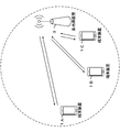
- FIG. 1 is a conceptual diagram of a wireless communication system according to one aspect of the present embodiment. It is an example showing the relationship between N slot symb , SCS setting ⁇ , and CP setting according to an aspect of the present embodiment.
- FIG. 9 is a schematic diagram illustrating an example of a resource grid in a subframe according to an aspect of the present embodiment.
- FIG. 11 is a diagram illustrating an example of a relationship between a PUCCH format and a length N PUCCH symb of the PUCCH format according to an aspect of the present embodiment.
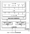
- FIG. 1 is a schematic block diagram illustrating a configuration of a terminal device 1 according to one aspect of the present embodiment.
- FIG. 2 is a schematic block diagram illustrating a configuration of a base station device 3 according to one aspect of the present embodiment.
- FIG. 9 is a diagram illustrating an example of a random access procedure according to an aspect of the embodiment.
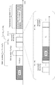
- FIG. 11 is a diagram illustrating an example of a channel access procedure according to an aspect of the present embodiment.
- FIG. 11 is a diagram illustrating an example of a channel access priority class (CAPC) and a CW adjustment procedure according to an aspect of the embodiment.
- CAC channel access priority class
- FIG. 1 is a conceptual diagram of a wireless communication system according to one aspect of the present embodiment.
- the wireless communication system includes terminal devices 1A to 1C and a base station device 3.
- the terminal devices 1A to 1C may also be referred to as a terminal device 1.
- the base station device 3 may include some or all of a communication device, a node, an NB (NodeB), an eNB, a gNB, a network device (a core network, a gateway), and an access point.
- the terminal device 1 may be referred to as a UE (User @ equipment).
- the base station apparatus 3 may configure one or both of an MCG (Master Cell Group) and an SCG (Secondary Cell Group).
- the MCG is a group of serving cells that includes at least PCell (Primary @ Cell).
- An SCG is a group of serving cells including at least a PSCell (Primary @ Secondary @ Cell).
- the PCell may be a serving cell provided based on an initial connection.
- the MCG may include one or more SCells (Secondary @ Cells).
- the SCG may include one or more SCells.
- MCG may be composed of one or more serving cells on EUTRA. Further, the SCG may be configured by one or a plurality of serving cells on the NR. Further, the MCG may be configured by one or a plurality of serving cells on the NR. Also, the SCG may be composed of one or more serving cells on EUTRA. In addition, the MCG and the SCG may be configured with one or a plurality of serving cells of either EUTRA or NR.
- MCG may be composed of one or more serving cells on EUTRA. Further, the SCG may be configured by one or more serving cells on the NR-U. Further, the MCG may be configured by one or a plurality of serving cells on the NR. Further, the SCG may be configured by one or more serving cells on the NR-U. Further, the MCG may be composed of one or more serving cells of one of EUTRA, NR and NR-U. Further, the SCG may be configured by one or more serving cells of one of EUTRA, NR, and NR-U.
- Operating bands applied to each of EUTRA, NR, and NR-U may be individually defined.
- the MCG may be configured by the first base station device.
- the SCG may be configured by a second base station device. That is, the PCell may be configured by the first base station device.
- PSCell may be configured by a second base station device. The first base station device and the second base station device may be the same as the base station device 3, respectively.
- At least OFDM Orthogonal Frequency Division Multiplex
- An OFDM symbol is a unit of the time domain of OFDM.
- An OFDM symbol includes at least one or more subcarriers.
- An OFDM symbol is converted into a time-continuous signal (time-continuous signal) in baseband signal generation.
- CP-OFDM Cyclic Prefix-Orthogonal Frequency Division Multiplex
- DFT-s-OFDM Discrete Fourier Transform-spread-Orthogonal Frequency Division Multiplex
- DFT-s-OFDM may be provided by applying Transform @ precoding to CP-OFDM.
- the SCS setting ⁇ may be set to any of 0, 1, 2, 3, 4, and / or 5.
- the SCS setting ⁇ may be given by an upper layer parameter.
- a time unit Tc is used to represent the length of the time domain.
- ⁇ f max may be the maximum value of the SCS supported in the wireless communication system according to an aspect of the present embodiment.
- ⁇ f ref may be 15 kHz.
- N f, ref may be 2048.
- the constant ⁇ may be a value indicating the relationship between the reference SCS and Tc .
- the constant ⁇ may be used for subframe length.
- the number of slots included in the subframe may be given based at least on the constant ⁇ .
- ⁇ f ref is a reference SCS
- N f, ref is a value corresponding to the reference SCS.
- Transmission of a signal in the downlink and / or transmission of a signal in the uplink is configured by a 10 ms frame.
- the frame is configured to include ten subframes.
- the length of the subframe is 1 ms.
- the length of the frame may be given regardless of the SCS ⁇ f. That is, the frame setting may be given regardless of the value of ⁇ .
- the length of the subframe may be given regardless of SCS ⁇ f. That is, the setting of the subframe may be given regardless of ⁇ .
- the number and index of slots included in one subframe may be given.
- the slot number n mu s is from 0 to N subframe in a subframe may be given in ascending order in the range of mu slot -1.
- the number and index of the slots included in one frame may be given to the SCS setting ⁇ .
- the slot number n mu s, f may be given from 0 in the frame N frame, in ascending order in the range of mu slot -1.
- Consecutive N slot symb OFDM symbols may be included in one slot.
- the N slot symb may be provided based at least on part or all of a CP (Cyclic Prefix) setting.
- the CP setting may be given based at least on upper layer parameters.
- the CP configuration may be provided based at least on dedicated RRC signaling.
- the slot number may also be called a slot index.
- FIG. 2 is an example showing a relationship among N slot symb , SCS setting ⁇ , and CP setting according to an aspect of the present embodiment.
- NCP normal CP
- ⁇ slot 4.
- NCP extended CP
- N slot symb 12
- Antenna ports are defined by the fact that the channel on which a symbol is transmitted at one antenna port can be estimated from the channel on which other symbols are transmitted at the same antenna port. If the large-scale property of a channel on which a symbol is transmitted at one antenna port can be estimated from the channel on which the symbol is transmitted at another antenna port, the two antenna ports are QCL (Quasi-Co-Located). ).
- the large-scale characteristics may include at least the long-range characteristics of the channel. Large-scale characteristics include delay spread (Dlay spread), Doppler spread (Doppler spread), Doppler shift (Doppler shift), average gain (average gain), average delay (average delay), and beam parameters (spatial Rx parameters). At least some or all of them may be included.
- the receiving beam assumed by the receiving side for the first antenna port and the receiving beam assumed by the receiving side for the second antenna port May be the same. That the first antenna port and the second antenna port are QCL with respect to the beam parameter means that the transmission beam assumed by the receiving side for the first antenna port and the transmission beam assumed by the receiving side for the second antenna port May be the same.
- the terminal device 1 assumes that the two antenna ports are QCL if the large-scale characteristics of the channel on which the symbol is transmitted on one antenna port can be estimated from the channel on which the symbol is transmitted on another antenna port May be done.
- the fact that the two antenna ports are QCLs may mean that the two antenna ports are QCLs.
- N size, ⁇ grid, x may indicate the number of resource blocks provided for SCS setting ⁇ for carrier x.
- N size, ⁇ grid, x may indicate the bandwidth of the carrier.
- N size, ⁇ grid, and x may correspond to the value of the upper layer parameter CarrierBandwidth.
- Carrier x may indicate either a downlink carrier or an uplink carrier. That is, x may be either “DL” or “UL”.
- N RB sc may indicate the number of subcarriers included in one resource block. N RB sc may be 12.
- At least one resource grid may be provided for each antenna port p and / or for each SCS setting ⁇ and / or for each setting of the transmission direction.
- the transmission direction includes at least a downlink (DL: DownLink) and an uplink (UL: UpLink).
- DL: DownLink downlink
- UL: UpLink uplink
- a set of parameters including at least part or all of the settings of the antenna port p, the SCS setting ⁇ , and the transmission direction may be referred to as a first wireless parameter set. That is, one resource grid may be provided for each first wireless parameter set.
- the wireless parameter set may be one or a plurality of sets including one or a plurality of wireless parameters (physical layer parameters or upper layer parameters).
- a carrier included in a serving cell is referred to as a downlink carrier (or a downlink component carrier).
- a carrier included in a serving cell is referred to as an uplink carrier (uplink component carrier).
- the downlink component carrier and the uplink component carrier may be collectively referred to as a component carrier (or a carrier).
- the type of the serving cell may be any of PCell, PSCell, and SCell.
- the PCell may be a serving cell identified based on at least the cell ID obtained from the SSB (Synchronization signal / Physical broadcast channel channel block) in the initial connection.
- the SCell may be a serving cell used in carrier aggregation.
- the SCell may be a serving cell provided at least based on dedicated RRC signaling.
- Each element in the resource grid provided for each first radio parameter set may be referred to as a resource element.
- the resource element is specified by an index k sc in the frequency domain and an index l sym in the time domain.
- the resource element is identified by a frequency domain index k sc and a time domain index l sym .
- the resource element specified by the frequency domain index k sc and the time domain index l sym may also be referred to as a resource element (k sc , l sym ).
- the frequency domain index k sc indicates any value from 0 to N ⁇ RB N RB sc ⁇ 1.
- N ⁇ RB may be the number of resource blocks given for SCS setting ⁇ .
- N ⁇ RB may be N size, ⁇ grid, x .
- the frequency domain index k sc may correspond to the subcarrier index k sc .
- the time domain index l sym may correspond to the OFDM symbol index l sym .
- FIG. 3 is a schematic diagram illustrating an example of a resource grid in a subframe according to an aspect of the present embodiment.
- the horizontal axis is the index l sym in the time domain
- the vertical axis is the index k sc in the frequency domain.
- the frequency domain resource grid including N ⁇ RB N RB sc subcarriers.
- the time domain of the resource grid may include 14.2 ⁇ OFDM symbols.
- One resource block is configured to include N RB sc subcarriers.
- the time domain of a resource block may correspond to one OFDM symbol.
- the time domain of the resource block may correspond to 14 OFDM symbols.
- the time domain of a resource block may correspond to one or more slots.
- the time domain of the resource block may correspond to one subframe.
- the terminal device 1 may be instructed to perform transmission and reception using only a subset of the resource grid.
- a subset of the resource grid is also referred to as BWP, which may be provided based at least on higher layer parameters and / or some or all of the DCI.
- BWP may also be referred to as CBP (Carrier Bandwidth Part).
- CBP Carrier Bandwidth Part
- the terminal device 1 may not be instructed to perform transmission and reception using all sets of the resource grid.
- the terminal device 1 may be instructed to perform transmission and reception using some frequency resources in the resource grid.
- One BWP may be configured from a plurality of resource blocks in the frequency domain.
- One BWP may be configured from a plurality of resource blocks that are continuous in the frequency domain.
- a BWP set for a downlink carrier may also be referred to as a downlink BWP.
- BWP set for an uplink carrier may also be referred to as uplink BWP.
- the BWP may be a subset of the carrier's band.
- One or more downlink BWPs may be set for each of the serving cells.
- One or more uplink BWPs may be configured for each of the serving cells.
- One or a plurality of downlink BWPs set for the serving cell may be configured as one active downlink BWP.
- the downlink BWP switch is used to deactivate one active downlink BWP and to activate inactive downlink BWPs other than the one active downlink BWP.
- Switching of the downlink BWP may be controlled by a BWP field included in the downlink control information. Switching of the downlink BWP may be controlled based on upper layer parameters.
- the DL-SCH may be received in the active downlink BWP.
- the PDCCH may be monitored.
- a PDSCH may be received.
- DL DL-SCH is not received in inactive downlink BWP.
- the PDCCH is not monitored. No CSI for inactive downlink BWP is reported.
- two or more downlink BWPs may not be set as the active downlink BWP.
- one uplink BWP may be set as the active uplink BWP.
- the uplink BWP switch is used to deactivate one active uplink BWP and activate (deactivate) inactive uplink BWPs other than the one active uplink BWP.
- Uplink BWP switching may be controlled by a BWP field included in downlink control information. Uplink BWP switching may be controlled based on upper layer parameters.
- ⁇ ⁇ ⁇ ⁇ UL-SCH may be transmitted in active uplink BWP.
- the PUCCH may be transmitted.
- the PRACH may be transmitted.
- the SRS may be transmitted.
- U UL-SCH is not transmitted in inactive uplink BWP.
- PUCCH is not transmitted in the inactive uplink BWP.
- the PRACH is not transmitted.
- no SRS is transmitted.
- two or more uplink BWPs may not be set as the active uplink BWP.
- the upper layer parameters are parameters included in the upper layer signal.
- the upper layer signal may be RRC (Radio Resource Control) signaling or MAC CE (Medium Access Control Control Element).
- the upper layer signal may be an RRC layer signal or a MAC layer signal.
- the upper layer signal may be common RRC signaling.
- the common RRC signaling may include at least some or all of the following features C1 to C3. Feature C1) Feature mapped to BCCH logical channel or CCCH logical channel C2) Feature C3) including at least ReconfigurationWithSync information element Mapped to PBCH
- the ReconfigurationWithSync information element may include information indicating a setting commonly used in the serving cell.
- the setting commonly used in the serving cell may include at least the setting of the PRACH.
- the setting of the PRACH may indicate at least one or a plurality of random access preamble indexes.
- the configuration of the PRACH may indicate at least a time / frequency resource of the PRACH.
- Common RRC signaling may include at least a common RRC parameter.
- the common RRC parameter may be a cell-specific parameter commonly used in the serving cell.
- the upper layer signal may be dedicated RRC signaling.
- the dedicated RRC signaling may include at least some or all of the following features D1 to D2. Feature D1) Feature Mapped to DCCH Logical Channel D2) Does Not Include ReconfigurationWithSync Information Element
- MIB Master Information Block
- SIB System Information Block
- higher layer messages that are mapped to the DCCH logical channel and that include at least the ReconfigurationWithSync information element may be included in the common RRC signaling.
- an upper layer message that is mapped to the DCCH logical channel and does not include the ReconfigurationWithSync information element may be included in dedicated RRC signaling.
- the MIB and the SIB may be collectively referred to as system information.
- $ SIB may indicate at least the time index of SSB.
- the SIB may include at least information related to the PRACH resource.
- the SIB may include at least information related to the setting of the initial connection.
- the ReconfigurationWithSync information element may include at least information related to the PRACH resource.
- the ReconfigurationWithSync information element may include at least information related to the setting of the initial connection.
- the dedicated RRC signaling may include at least a dedicated RRC parameter.
- the dedicated RRC parameter may be a (UE-specific) parameter used exclusively for the terminal device 1.
- Dedicated RRC signaling may include at least common RRC parameters.
- ⁇ Common RRC parameters and dedicated RRC parameters may also be referred to as upper layer parameters.
- An uplink physical channel may correspond to a set of resource elements that carry information that occurs in higher layers.
- An uplink physical channel is a physical channel used in an uplink carrier. In the wireless communication system according to one aspect of the present embodiment, at least some or all of the following uplink physical channels are used.
- ⁇ PUCCH Physical Uplink Control CHannel
- PUSCH Physical Uplink Shared CHannel
- PRACH Physical Random Access CHannel
- the PUCCH may be used to transmit uplink control information (UCI).
- the uplink control information includes part or all of HARQ-ACK (Hybrid Automatic Transmission Repeat Request ACKnowledgement) information corresponding to channel state information (CSI), scheduling request (SR), and transport block (TB).
- CSI channel state information
- SR scheduling request
- TB transport block
- the TB may be called a MAC PDU (Medium Access Control Protocol Data Unit), a DL-SCH (Downlink-Shared Channel) or a PDSCH (Physical Downlink Shared Channel).
- MAC PDU Medium Access Control Protocol Data Unit
- DL-SCH Downlink-Shared Channel
- PDSCH Physical Downlink Shared Channel
- One or more types of uplink control information may be multiplexed on the PUCCH.
- the multiplexed PUCCH may be transmitted. That is, a plurality of HARQ-ACKs may be multiplexed on the PUCCH, a plurality of CSIs may be multiplexed, a plurality of SRs may be multiplexed, or the HARQ-ACK and the CSI may be multiplexed.
- HARQ-ACK and SR may be multiplexed, or may be multiplexed with another UCI type.
- the HARQ-ACK information may include at least a HARQ-ACK bit corresponding to the TB.
- the HARQ-ACK bit may indicate ACK (acknowledgement) or NACK (negative-acknowledgement) corresponding to the TB.
- the ACK may be a value indicating that decoding of the TB has been successfully completed.
- NACK may be a value indicating that decoding of the TB has not been successfully completed.
- the HARQ-ACK information may include at least one HARQ-ACK codebook including one or more HARQ-ACK bits. The fact that the HARQ-ACK bit corresponds to one or more TBs may correspond to the fact that the HARQ-ACK bit corresponds to a PDSCH including the one or more TBs.
- the HARQ-ACK bit may indicate ACK or NACK corresponding to one CBG (Code Block Group) included in the TB.
- HARQ-ACK may also be referred to as HARQ feedback, HARQ information, and HARQ control information.
- SR may be at least used to request PUSCH resources for initial transmission. Also, the SR may be used to request UL-SCH resources for new transmissions.
- the SR bit may be used to indicate either positive SR (positive SR) or negative SR (negative SR). The fact that the SR bit indicates a positive SR may also be referred to as “a positive SR is transmitted”.
- a positive SR may indicate that the terminal device 1 requests a PUSCH resource for initial transmission.
- a positive SR may indicate that the SR is triggered by higher layers.
- the positive SR may be transmitted when the upper layer instructs to transmit the SR.
- the fact that the SR bit indicates a negative SR may also be referred to as “a negative SR is transmitted”.
- a negative SR may indicate that PUSCH resources for initial transmission are not required by the terminal device 1.
- a negative SR may indicate that no SR is triggered by higher layers.
- a negative SR may be sent if no higher layer indicates to send the SR.
- the SR bit may be used to indicate either a positive SR or a negative SR for any one or more SR configurations (SR configuration).
- Each of the one or more SR settings may correspond to one or more logical channels.
- the positive SR for a certain SR setting may be a positive SR for any or all of one or more logical channels corresponding to the certain SR setting.
- a negative SR may not correspond to a particular SR setting. Indicating a negative SR may indicate a negative SR for all SR settings.
- the SR setting may be an SR-ID (Scheduling Request ID).
- the SR-ID may be given by an upper layer parameter.
- CSI may include at least a part or all of a channel quality indicator (CQI), a precoder matrix indicator (PMI), and a rank indicator (RI).
- CQI is an index related to channel quality (for example, propagation strength)
- PMI is an index indicating a precoder.
- RI is an index indicating the transmission rank (or the number of transmission layers).
- the CSI may be provided based at least on receiving a physical signal (eg, CSI-RS) used at least for channel measurement.
- the CSI may include a value selected by the terminal device 1.
- the CSI may be selected by the terminal device 1 based at least on receiving a physical signal used at least for channel measurement.
- Channel measurements may include interference measurements.
- the CSI report is a CSI report.
- the CSI report may include CSI part 1 and / or CSI part 2.
- CSI part 1 may be configured to include at least part or all of wideband channel quality information (wideband CQI), wideband precoder matrix indicator (wideband PMI), and RI.
- the number of bits of the CSI part 1 multiplexed on the PUCCH may be a predetermined value regardless of the value of the RI of the CSI report.
- the number of bits of the CSI part 2 multiplexed on the PUCCH may be given based on the value of the RI of the CSI report.
- the rank index of the CSI report may be a value of the rank index used for calculating the CSI report.
- the RI of the CSI information may be a value indicated by an RI field included in the CSI report.
- the set of RIs allowed in the CSI report may be some or all of 1-8.
- the set of RIs allowed in the CSI report may be given at least based on the parameter RankRestriction of the upper layer. If the set of RIs allowed in the CSI report includes only one value, the RI of the CSI report may be the one value.
- the priority may be set for the CSI report.
- the priority of the CSI report may be set for the behavior (processing) of the time domain of the CSI report, the type of the content of the CSI report, the index of the CSI report, and / or the serving cell in which the measurement of the CSI report is set. It may be given at least based on part or all of the index.
- the setting relating to the time domain behavior (processing) of the CSI report may be performed in a non-periodic manner (aperiodic), in a semi-persistent manner in the CSI report, or in a quasi-static manner. May be set to indicate whether the setting is to be performed.
- the content type of the CSI report may indicate whether the CSI report includes Layer 1 RSRP (Reference Signals Received Power).
- the index of the CSI report may be given by an upper layer parameter.
- PUCCH supports PUCCH format (PUCCH format 0 to PUCCH format 4).
- the PUCCH format may be transmitted on the PUCCH.
- the transmission of the PUCCH format may be the transmission of the PUCCH.
- FIG. 4 is a diagram illustrating an example of the relationship between the PUCCH format and the length N PUCCH symb of the PUCCH format according to an aspect of the present embodiment.
- the length N PUCCH symb of PUCCH format 0 is 1 or 2OFDM symbol.
- the length N PUCCH symb of PUCCH format 1 is any one of 4 14OFDM symbols.
- the length N PUCCH symb of PUCCH format 2 is 1 or 2OFDM symbol.
- the length N PUCCH symb of PUCCH format 3 is any one of 4 14OFDM symbols.
- the length N PUCCH symb of PUCCH format 4 is any one of 4 14OFDM symbols.
- the PUSCH is used at least to transmit a TB (MAC PDU, UL-SCH).
- the PUSCH may be used to transmit at least part or all of the TB, HARQ-ACK information, CSI, and SR.
- the PUSCH is used at least to transmit a random access message 3 (message 3 (Msg3)) corresponding to the RAR (Msg2) and / or RAR grant in the random access procedure.
- Msg3 messages 3 corresponding to the RAR (Msg2) and / or RAR grant in the random access procedure.
- PRACH is used at least for transmitting a random access preamble (random access message 1, message 1 (Msg1)).
- the PRACH includes an initial connection establishment procedure, a handover procedure, a connection re-establishment procedure, an initial access procedure, synchronization for PUSCH transmission (timing adjustment), and a request for a resource for the PUSCH. It may be used at least to indicate part or all.
- the random access preamble may be used to notify the base station device 3 of an index (random access preamble index) given from an upper layer of the terminal device 1.
- the random access preamble may be given by cyclically shifting the Zadoff-Chu sequence corresponding to the physical root sequence index u.
- the Zadoff-Chu sequence may be generated based on the physical root sequence index u.
- a plurality of random access preambles may be defined in one serving cell (serving @ cell).
- the random access preamble may be specified based at least on the index of the random access preamble. Different random access preambles corresponding to different indexes of the random access preamble may correspond to different combinations of the physical root sequence index u and the cyclic shift.
- the physical root sequence index u and the cyclic shift may be given based at least on information included in the system information.
- the physical root sequence index u may be an index for identifying a sequence included in the random access preamble.
- the random access preamble may be specified based at least on the physical root sequence index u.
- the following uplink physical signals are used in uplink wireless communication.
- the uplink physical signal may not be used for transmitting information output from the upper layer, but is used by the physical layer.
- ⁇ UL DMRS UpLink Demodulation Reference Signal
- SRS Sounding Reference Signal
- UL PTRS UpLink Phase Tracking Reference Signal
- ⁇ UL ⁇ DMRS is related to the transmission of PUSCH and / or PUCCH.
- UL @ DMRS is multiplexed with PUSCH or PUCCH.
- the base station apparatus 3 may use UL @ DMRS in order to perform the PUSCH or PUCCH propagation path correction.
- transmitting the PUSCH and the UL @ DMRS related to the PUSCH together is simply referred to as transmitting the PUSCH.
- transmitting the PUCCH and the UL @ DMRS related to the PUCCH together is simply referred to as transmitting the PUCCH.
- UL @ DMRS related to PUSCH is also referred to as UL @ DMRS for PUSCH.
- UL @ DMRS related to PUCCH is also referred to as UL @ DMRS for PUCCH.
- the SRS may not be related to PUSCH or PUCCH transmission.
- the base station device 3 may use the SRS for measuring the channel state.
- the SRS may be transmitted at the end of a subframe in an uplink slot or a predetermined number of OFDM symbols from the end.
- ⁇ UL ⁇ PTRS may be a reference signal used at least for phase tracking.
- the UL @ PTRS may be associated with a UL @ DMRS group that includes at least an antenna port used for one or more UL @ DMRS.
- the association between the UL @ PTRS and the UL @ DMRS group may be that at least a part or all of the antenna ports of the UL @ PTRS and the antenna ports included in the UL @ DMRS group are QCLs.
- the UL @ DMRS group may be identified based at least on the antenna port with the smallest index in the UL @ DMRS included in the UL @ DMRS group.
- UL @ PTRS may be mapped to the antenna port with the smallest index in one or more antenna ports to which one codeword is mapped.
- UL @ PTRS may be mapped to a first layer if one codeword is at least mapped to the first layer and the second layer.
- UL @ PTRS may not be mapped to the second layer.
- the index of the antenna port to which UL @ PTRS is mapped may be given based at least on the downlink control information.
- the following downlink physical channel is used in downlink wireless communication from the base station device 3 to the terminal device 1.
- the downlink physical channel is used by the physical layer to transmit information output from an upper layer.
- ⁇ PBCH Physical Broadcast Channel
- PDCCH Physical Downlink Control Channel
- PDSCH Physical Downlink Shared Channel
- $ PBCH is at least used to transmit MIB and / or PBCH payloads.
- the PBCH payload may include at least information indicating an index related to SSB transmission timing (SSB @ occasion).
- the PBCH payload may include information related to the SSB identifier (index).
- the PBCH may be transmitted based on a predetermined transmission interval.
- the PBCH may be transmitted at intervals of 80 milliseconds (ms).
- the PBCH may be transmitted at an interval of 160 ms.
- the content of the information included in the PBCH may be updated every 80 ms. Part or all of the information included in the PBCH may be updated every 160 ms.
- the PBCH may be configured with 288 subcarriers.
- the PBCH may be configured to include 2, 3, or 4 OFDM symbols.
- the MIB may include information related to the identifier (index) of the SSB.
- the MIB may include information indicating a slot number in which the PBCH is transmitted, a subframe number, and / or at least a part of a radio frame number.
- the PDCCH is used at least for transmission of downlink control information (DCI).
- the PDCCH may be transmitted including at least DCI.
- the PDCCH may be transmitted including DCI.
- DCI may also be referred to as DCI format.
- the DCI may indicate at least either a downlink grant or an uplink grant.
- the DCI format used for PDSCH scheduling may also be referred to as a downlink DCI format.
- the DCI format used for PUSCH scheduling may also be referred to as an uplink DCI format.
- a downlink grant may also be referred to as a downlink assignment or a downlink assignment.
- the uplink DCI format includes at least one or both of DCI format 0_0 and DCI format 0_1.
- the DCI format 0_0 may be configured to include at least a part or all of 1A to 1F.
- the DCI format specifying field may be used at least to indicate whether the DCI format including the DCI format specifying field corresponds to one or a plurality of DCI formats.
- the one or more DCI formats may be provided based at least on part or all of DCI format 1_0, DCI format 1_1, DCI format 0_0, and / or DCI format 0_1.
- the frequency domain resource allocation field may be at least used to indicate frequency resource allocation for a PUSCH scheduled by a DCI format including the frequency domain resource allocation field.
- the time domain resource allocation field may be used at least to indicate time resource allocation for a PUSCH scheduled according to the DCI format including the time domain resource allocation field.
- the frequency hopping flag field may be used at least to indicate whether frequency hopping is applied to a PUSCH scheduled according to the DCI format including the frequency hopping flag field.
- the MCS field may be used at least to indicate a modulation scheme for a PUSCH scheduled by a DCI format including the MCS field and / or a part or all of a target coding rate.
- the target coding rate may be a target coding rate for the PUSCH TB.
- the size of the TB (TBS) may be given based at least on the target code rate.
- the first CSI request field is used at least to indicate CSI reporting.
- the size of the first CSI request field may be a predetermined value.
- the size of the first CSI request field may be zero, one, two, or three.
- the size of the first CSI request field may be determined according to the number of CSI settings set in the terminal device 1.
- the DCI format 0_1 is configured to include at least a part or all of 2A to 2G.
- the BWP field may be used to indicate the uplink BWP to which the PUSCH scheduled according to DCI format 0_1 is mapped.
- the second CSI request field is used at least to indicate CSI reporting.
- the size of the second CSI request field may be given at least based on an upper layer parameter ReportTriggerSize.
- the downlink DCI format includes at least one or both of DCI format 1_0 and DCI format 1_1.
- the DCI format 1_0 may be configured to include at least a part or all of 3A to 3H.
- the timing indication field from the PDSCH to the HARQ feedback may be a field indicating the timing K1.
- the index of the slot including the last OFDM symbol of the PDSCH is slot n
- the index of the PUCCH including at least HARQ-ACK corresponding to the transport block included in the PDSCH or the index of the slot including the PUSCH is n + K1. Is also good.
- the index of the slot including the last OFDM symbol of the PDSCH is slot n
- the first OFDM symbol of the PUCCH or the first OFDM symbol of the PUSCH including at least the HARQ-ACK corresponding to the transport block included in the PDSCH is The index of the included slot may be n + K1.
- the PUCCH resource indication field may be a field indicating an index of one or more PUCCH resources included in the PUCCH resource set.
- the DCI format 1_1 may be configured to include at least a part or all of 4A to 4J.
- the BWP field may be used to indicate a downlink BWP to which a PDSCH scheduled according to DCI format 1_1 is mapped.
- DCI format 2 may include a parameter used for transmission power control of PUSCH or PUCCH.
- the number of resource blocks indicates the number of resource blocks in the frequency domain unless otherwise specified.
- the resource block index is assigned in ascending order from a resource block mapped to a low frequency region to a resource block mapped to a high frequency region.
- the resource block is a general term for a common resource block and a physical resource block.
- One physical channel may be mapped to one serving cell.
- One physical channel may be mapped to one CBP set to one carrier included in one serving cell.
- the terminal device 1 is provided with one or a plurality of control resource sets (CORESET).
- the terminal device 1 monitors the PDCCH in one or a plurality of resets.
- $ CORESET may indicate a time-frequency domain to which one or more PDCCHs may be mapped.
- CORESET may be an area where the terminal device 1 monitors the PDCCH.
- CORRESET may be configured by a continuous resource (Localized @ resource).
- the CORESET may be configured by a discontinuous resource (distributed @ resource).
- the unit of the mapping of the coreset may be a resource block.
- the unit of the mapping of the coreset may be six resource blocks.
- the mapping unit of the coreset may be an OFDM symbol.
- the unit of the mapping of the reset may be one OFDM symbol.
- the CORESET frequency domain may be provided based on at least a higher layer signal and / or DCI.
- the CORESET time domain may be provided based at least on upper layer signals and / or DCI.
- a certain RESET may be a common RESET (Common) RESET).
- the common coreset may be a coreset commonly set for a plurality of terminal devices 1.
- the common CORESET may be given based at least on MIB, SIB, common RRC signaling, and part or all of the cell ID. For example, a time resource and / or a frequency resource of CODE configured to monitor a PDCCH used for scheduling of SIB may be provided based at least on MIB.
- a certain CORESET may be a dedicated CORESET (Dedicated $ CORESET).
- the dedicated RESET may be a RESET that is set to be used exclusively for the terminal device 1.
- the dedicated coreset may be provided based at least on dedicated RRC signaling.
- a set of PDCCH candidates monitored by the terminal device 1 may be defined in terms of a search area. That is, the set of PDCCH candidates monitored by the terminal device 1 may be given by the search area.
- the search area may be configured to include one or more PDCCH candidates of one or more aggregation levels (Aggregationgreglevel).
- the aggregation level of the PDCCH candidates may indicate the number of CCEs constituting the PDCCH.
- the terminal device 1 may monitor at least one or a plurality of search areas in a slot where DRX (Discontinuous reception) is not set. DRX may be given based at least on upper layer parameters. The terminal device 1 may monitor at least one or a plurality of search area sets (Search ⁇ space ⁇ set) in slots in which DRX is not set.
- DRX discontinuous reception
- the terminal device 1 may monitor at least one or a plurality of search area sets (Search ⁇ space ⁇ set) in slots in which DRX is not set.
- the search area set may include at least one or a plurality of search areas.
- the type of the search area set is a type 0 PDCCH common search area (common @ search ⁇ space), a type 0a PDCCH common search area, a type 1 PDCCH common search area, a type 2 PDCCH common search area, a type 3 PDCCH common search area, and / or a UE-specific PDCCH search. It may be any of the regions.
- the type 0 PDCCH common search area, the type 0a PDCCH common search area, the type 1 PDCCH common search area, the type 2 PDCCH common search area, and the type 3 PDCCH common search area may be referred to as CSS (Common Search Space).
- the UE-specific PDCCH search area may also be referred to as USS (UE specific search space).
- Each of the search area sets may be associated with one control resource set.
- Each of the search area sets may be at least included in one control resource set.
- an index of a control resource set associated with the search area set may be given.
- the type 0 PDCCH common search area may be at least used for a DCI format with a CRC (Cyclic Redundancy Check) sequence scrambled by an SI-RNTI (System Information-Radio Network Temporary Identifier).
- the setting of the type 0 PDCCH common search area may be given based on at least four bits of LSB (Least Significant Bits) of the upper layer parameter PDCCH-ConfigSIB1.
- the upper layer parameter PDCCH-ConfigSIB1 may be included in the MIB.
- the setting of the type-0 PDCCH common search area may be given based at least on the upper layer parameter SearchSpaceZero.
- the interpretation of the bits of the upper layer parameter SearchSpaceZero may be the same as the interpretation of the four bits of the LSB of the upper layer parameter PDCCH-ConfigSIB1.
- the setting of the type-0 PDCCH common search area may be given based at least on the upper layer parameter SearchSpaceSIB1.
- the upper layer parameter SearchSpaceSIB1 may be included in the upper layer parameter PDCCH-ConfigCommon.
- the PDCCH detected in the type-0 PDCCH common search area may be used at least for scheduling of the PDSCH transmitted including the SIB1.
- SIB1 is a type of SIB.
- SIB1 may include scheduling information of SIBs other than SIB1.
- the terminal device 1 may receive the upper layer parameter PDCCH-ConfigCommon in EUTRA.
- the terminal device 1 may receive the upper layer parameter PDCCH-ConfigCommon in the MCG.
- the type 0a PDCCH common search area may be used at least for a DCI format with a CRC (Cyclic Redundancy Check) sequence scrambled by an SI-RNTI (System Information-Radio Network Temporary Identifier).
- the setting of the type 0a PDCCH common search area may be given at least based on the upper layer parameter SearchSpaceOtherSystemInformation.
- the upper layer parameter SearchSpaceOtherSystemInformation may be included in SIB1.
- the upper layer parameter SearchSpaceOtherSystemInformation may be included in the upper layer parameter PDCCH-ConfigCommon.
- the PDCCH detected in the type-0 PDCCH common search area may be at least used for scheduling the PDSCH transmitted including SIBs other than SIB1.
- the type 1 PDCCH common search area is accompanied by a CRC sequence scrambled by RA-RNTI (Random Access-Radio Network Temporary Identifier) and / or a CRC sequence scrambled by TC-RNTI (Temporary Common-Radio Network Temporary Identifier). It may be used at least for the DCI format.
- the RA-RNTI may be given based at least on the time / frequency resource of the random access preamble transmitted by the terminal device 1.
- the TC-RNTI is provided by a PDSCH (also referred to as random access message 2, message 2 (Msg2), or random access response (RAR)) scheduled in a DCI format with a CRC sequence scrambled by RA-RNTI. You may be.
- the type-1 PDCCH common search area may be provided based at least on the parameter ra-SearchSpace of the upper layer.
- the parameter ra-SearchSpace of the upper layer may be included in SIB1.
- the upper layer parameter ra-SearchSpace may be included in the upper layer parameter PDCCH-ConfigCommon.
- the type 2 PDCCH common search area may be used for a DCI format with a CRC sequence scrambled by P-RNTI (Paging- Radio Network Temporary Identifier).
- P-RNTI Paging- Radio Network Temporary Identifier
- the P-RNTI may be used at least for transmission of a DCI format including information for notifying a change of the SIB.
- the type-2 PDCCH common search area may be given based at least on the upper layer parameter PagingSearchSpace.
- the parameter PagingSearchSpace of the upper layer may be included in SIB1.
- the upper layer parameter PagingSearchSpace may be included in the upper layer parameter PDCCH-ConfigCommon.
- the Type 3 PDCCH common search region may be used for a DCI format with a CRC sequence scrambled by a C-RNTI (Cell-Radio Network Network Temporary Identifier).
- the C-RNTI is a PDSCH (also referred to as random access message 4, message 4 (Msg4), or contention resolution) scheduled in a DCI format with a CRC sequence scrambled by the TC-RNTI. It may be given at least based on.
- the type 3 PDCCH common search region may be a search region set given when the parameter SearchSpaceType of the upper layer is set to common.
- the UE-specific PDCCH search region may be at least used for a DCI format with a CRC sequence scrambled by C-RNTI.
- the type-0 PDCCH common search area, the type-0a PDCCH common search area, the type-1 PDCCH common search area, and / or the type-2 PDCCH common search area includes a CRC scrambled by the C-RNTI. It may be used at least for the DCI format with sequences.
- the search area set given at least based on any of the parameters PagingSearchSpace may be used at least for the DCI format with a CRC sequence scrambled with C-RNTI.
- Common CORESET may include at least one or both of CSS and USS.
- the dedicated coreset may include at least one or both of CSS and USS.
- the physical resource of the search area is configured by a control channel constituent unit (CCE: Control Channel Element).
- CCE Control Channel Element
- the CCE is composed of six resource element groups (REG: ⁇ Resource ⁇ Element ⁇ Group).
- the REG may be configured by one OFDM symbol of one PRB (Physical Resource Block). That is, the REG may be configured to include 12 resource elements (RE: ⁇ Resource ⁇ Element).
- the PRB may be simply referred to as a resource block (RB).
- the PDSCH is used at least to transmit TB. Further, the PDSCH may be used at least for transmitting the random access message 2 (RAR, Msg2). Also, the PDSCH may be used at least for transmitting system information including parameters used for initial access.
- RAR random access message 2
- Msg2 the random access message 2
- the following downlink physical signals are used in downlink wireless communication.
- the downlink physical signal may not be used for transmitting information output from the upper layer, but is used by the physical layer.
- ⁇ Synchronization signal ⁇ DL DMRS (DownLink DeModulation Reference Signal) ⁇ CSI-RS (Channel State Information-Reference Signal) ⁇ DL PTRS (DownLink Phase Tracking Reference Signal) ⁇ TRS (Tracking Reference Signal)
- the synchronization signal is used for the terminal device 1 to synchronize in the downlink frequency domain and / or the time domain.
- the synchronization signal includes PSS (Primary @ Synchronization @ Signal) and SSS (Secondary @ Synchronization @ Signal).
- SSB (SS / PBCH block) is configured to include at least a part or all of PSS, SSS, and PBCH. Some or all of the antenna ports of the PSS, the SSS, and the PBCH included in the SS block may be the same. Some or all of the PSS, SSS, and PBCH included in the SSB may be mapped to consecutive OFDM symbols. Each of the PSS, SSS, and some or all of the PBCH included in the SSB may have the same CP setting. The same value may be applied to the SCS setting ⁇ for each of some or all of the PSS, SSS, and PBCH included in the SSB.
- ⁇ DL ⁇ DMRS is related to the transmission of PBCH, PDCCH and / or PDSCH.
- DL @ DMRS is multiplexed on PBCH, PDCCH, and / or PDSCH.
- the terminal device 1 may use the PBCH, the PDCCH, or the DL @ DMRS corresponding to the PDSCH to perform propagation path correction on the PBCH, the PDCCH, or the PDSCH.
- the transmission of the PBCH and the DL @ DMRS associated with the PBCH may be referred to as the transmission of the PBCH.
- the fact that the PDCCH and the DL @ DMRS associated with the PDCCH are transmitted together may be simply referred to as the transmission of the PDCCH.
- a DL @ DMRS associated with a PBCH may also be referred to as a DL @ DMRS for the PBCH.
- a DL @ DMRS associated with a PDSCH may also be referred to as a DL @ DMRS for PDSCH.
- a DL @ DMRS associated with a PDCCH may also be referred to as a DL @ DMRS associated with a PDCCH.
- ⁇ DL ⁇ DMRS may be a reference signal individually set in the terminal device 1.
- the DL DMRS sequence may be given at least based on parameters individually set in the terminal device 1.
- the DL DMRS sequence may be provided based on at least a UE-specific value (eg, C-RNTI, etc.).
- DL @ DMRS may be sent separately for PDCCH and / or PDSCH.
- CSI-RS may be a signal used at least for calculating CSI.
- the CSI-RS may be used to measure RSRP (Reference Signal Received Power) or RSRQ (Reference Signal Received Quality).
- the CSI-RS pattern assumed by the terminal device 1 may be given at least by a parameter of an upper layer.
- PTRS may be a signal used at least for phase noise compensation.
- the pattern of the PTRS assumed by the terminal device 1 may be given based on at least a parameter of an upper layer and / or DCI.
- the DL PTRS may be associated with a DL DMRS group that includes at least an antenna port used for one or more DL DMRS.
- the association between the DL @ PTRS and the DL @ DMRS group may be that part or all of the antenna port of the DL @ PTRS and the antenna port included in the DL @ DMRS group are at least QCL.
- the DL @ DMRS group may be identified based at least on the antenna port with the smallest index in the DL @ DMRS included in the DL @ DMRS group.
- TRS may be a signal used at least for time and / or frequency synchronization.
- the TRS pattern assumed by the terminal device may be given based at least on upper layer parameters and / or DCI.
- the downlink physical channel and the downlink physical signal may also be referred to as a downlink signal.
- the uplink physical channel and the uplink physical signal may also be referred to as an uplink signal.
- the downlink signal and the uplink signal may be collectively referred to as a physical signal or a signal.
- the downlink signal and the uplink signal may be collectively referred to as a signal.
- the downlink physical channel and the uplink physical channel may be collectively referred to as a physical channel.
- the downlink physical signal and the uplink physical signal may be collectively referred to as a physical signal.
- BCH Broadcast CHannel
- UL-SCH Uplink-Shared CHannel
- DL-SCH Downlink-Shared CHannel
- HARQ control is performed for each TB in the MAC layer.
- the TB is a unit of data that the MAC layer delivers to the physical layer. In the physical layer, TBs are mapped to codewords, and modulation processing is performed for each codeword.
- the base station device 3 and the terminal device 1 exchange (transmit and receive) upper layer signals in the upper layer (higher layer).
- the base station device 3 and the terminal device 1 may transmit and receive RRC signaling (RRC message, RRC information, RRC information element) in a radio resource control (RRC) layer.
- RRC radio resource control
- the base station device 3 and the terminal device 1 may transmit and receive MAC @ CE (Control @ Element) in the MAC layer.
- RRC signaling and / or MAC @ CE are also referred to as higher layer signaling.
- the PUSCH and PDSCH may be at least used for transmitting RRC signaling and / or MAC CE.
- the RRC signaling transmitted by the PDSCH from the base station device 3 may be a common signaling to a plurality of terminal devices 1 in the serving cell. Signaling common to a plurality of terminal devices 1 in the serving cell may be referred to as common RRC signaling.
- the RRC signaling transmitted by the PDSCH from the base station device 3 may be signaling dedicated to a certain terminal device 1 (which may also be referred to as dedicated signaling or UE specific signaling).
- the dedicated signaling for the terminal device 1 may also be referred to as dedicated RRC signaling.
- Upper layer parameters unique to the serving cell may be transmitted using common signaling for a plurality of terminal devices 1 in the serving cell or dedicated signaling for a certain terminal device 1. UE-specific upper layer parameters may be transmitted to a certain terminal device 1 using dedicated signaling.
- the BCCH Broadcast Control CHannel
- the CCCH Common Control CHannel
- the DCCH Dedicated Control CHannel
- the BCCH is an upper layer channel used for transmitting MIB.
- the CCCH Common ⁇ Control ⁇ CHannel
- the DCCH is an upper layer channel used at least for transmitting dedicated control information (dedicated control information) to the terminal device 1.
- the DCCH may be used, for example, for the RRC-connected terminal device 1.
- the BCCH in the logical channel may be mapped to the BCH, DL-SCH, or UL-SCH in the transport channel.
- the CCCH in a logical channel may be mapped to a DL-SCH or a UL-SCH in a transport channel.
- the DCCH in the logical channel may be mapped to the DL-SCH or UL-SCH in the transport channel.
- UUL-SCH in transport channel may be mapped to PUSCH in physical channel.
- the DL-SCH in the transport channel may be mapped to the PDSCH in the physical channel.
- the BCH in the transport channel may be mapped to the PBCH in the physical channel.
- FIG. 5 is a schematic block diagram illustrating a configuration of the terminal device 1 according to an aspect of the present embodiment.
- the terminal device 1 is configured to include a wireless transmission / reception unit 10 and an upper layer processing unit 14.
- the wireless transmission / reception unit 10 includes at least a part or all of an antenna unit 11, an RF (RadioRFrequency) unit 12, and a baseband unit 13.
- the upper layer processing unit 14 is configured to include at least a part or all of the medium access control layer processing unit 15 and the radio resource control layer processing unit 16.
- the wireless transmission / reception unit 10 may also be referred to as a transmission unit, a reception unit, a physical layer processing unit, and / or a lower layer processing unit.
- the upper layer processing unit 14 outputs the uplink data (TB, UL-SCH) generated by the operation of the user or the like to the wireless transmission / reception unit 10.
- the upper layer processing unit 14 performs processing of a MAC layer, a packet data integration protocol (PDCP) layer, a radio link control (RLC) layer, and an RRC layer.
- PDCP packet data integration protocol
- RLC radio link control
- the medium access control layer processing unit 15 provided in the upper layer processing unit 14 performs processing of the MAC layer.
- the radio resource control layer processing unit 16 included in the upper layer processing unit 14 performs processing of the RRC layer.
- the radio resource control layer processing unit 16 manages various setting information / parameters of the own device.
- the radio resource control layer processing unit 16 sets various setting information / parameters based on the upper layer signal received from the base station device 3. That is, the radio resource control layer processing unit 16 sets various setting information / parameters based on information indicating various setting information / parameters received from the base station device 3.
- the parameters may be upper layer parameters and / or information elements.
- the wireless transmission / reception unit 10 performs physical layer processing such as modulation, demodulation, encoding, and decoding.
- the wireless transmission / reception unit 10 separates, demodulates, and decodes the received physical signal, and outputs the decoded information to the upper layer processing unit 14. These processes may be referred to as reception processes.
- the wireless transmission / reception unit 10 generates a physical signal (uplink signal) by modulating, encoding, and generating a baseband signal (conversion to a time continuous signal), and transmits the physical signal (uplink signal) to the base station device 3. These processes may be referred to as transmission processes.
- the RF unit 12 converts a signal received via the antenna unit 11 into a baseband signal by quadrature demodulation (down-conversion), and removes unnecessary frequency components.
- the RF unit 12 outputs the processed analog signal to the baseband unit.
- the baseband unit 13 converts an analog signal input from the RF unit 12 into a digital signal.
- the baseband unit 13 removes a portion corresponding to the CP from the converted digital signal, performs fast Fourier transform (FFT) on the signal from which the CP has been removed, and extracts a signal in the frequency domain.
- FFT fast Fourier transform
- the baseband unit 13 performs an inverse fast Fourier transform (IFFT) on the data, generates an OFDM symbol, adds a CP to the generated OFDM symbol, generates a baseband digital signal, and converts the baseband digital signal. Convert to analog signal.
- the baseband unit 13 outputs the converted analog signal to the RF unit 12.
- IFFT inverse fast Fourier transform
- the RF unit 12 removes unnecessary frequency components from the analog signal input from the baseband unit 13 using a low-pass filter, upconverts the analog signal to a carrier frequency, and transmits the analog signal via the antenna unit 11. Further, the RF unit 12 amplifies the power. Further, the RF unit 12 may have a function of controlling transmission power.
- the RF unit 12 is also called a transmission power control unit.
- FIG. 6 is a schematic block diagram illustrating a configuration of the base station device 3 according to one aspect of the present embodiment.
- the base station device 3 is configured to include a radio transmission / reception unit 30 and an upper layer processing unit 34.
- the wireless transmission / reception unit 30 includes an antenna unit 31, an RF unit 32, and a baseband unit 33.
- the upper layer processing unit 34 includes a medium access control layer processing unit 35 and a radio resource control layer processing unit 36.
- the wireless transmission / reception unit 30 is also referred to as a transmission unit, a reception unit, or a physical layer processing unit.
- the upper layer processing unit 34 performs processing of the MAC layer, PDCP layer, RLC layer, and RRC layer.
- the medium access control layer processing unit 35 included in the upper layer processing unit 34 performs processing of the MAC layer.
- the radio resource control layer processing unit 36 included in the upper layer processing unit 34 performs processing of the RRC layer.
- the radio resource control layer processing unit 36 generates downlink data (TB, DL-SCH), system information, an RRC message, a MAC @ CE, etc., allocated to the PDSCH, or obtains it from an upper node, and Output. Further, the radio resource control layer processing unit 36 manages various setting information / parameters of each terminal device 1.
- the radio resource control layer processing unit 36 may set various setting information / parameters for each of the terminal devices 1 via a signal of an upper layer. That is, the radio resource control layer processing unit 36 transmits / reports information indicating various setting information / parameters.
- the basic functions of the wireless transmitting / receiving unit 30 are the same as those of the wireless transmitting / receiving unit 10, and a description thereof will be omitted.
- the physical signal generated by the wireless transmission / reception unit 30 is transmitted to the terminal device 1 (that is, transmission processing is performed). Further, the wireless transmission / reception unit 30 performs a reception process of the received physical signal.
- the medium access control layer processing unit 15 and / or 35 may be referred to as a MAC entity.
- Each of the units denoted by reference numerals 10 to 16 included in the terminal device 1 may be configured as a circuit.
- Each of the units denoted by reference numerals 30 to 36 included in the base station device 3 may be configured as a circuit.
- Some or all of the units denoted by reference numerals 10 to 16 included in the terminal device 1 may be configured as a memory and a processor connected to the memory.
- Part or all of the units denoted by reference numerals 30 to 36 included in the base station device 3 may be configured as a memory and a processor connected to the memory.
- Various aspects (operations and processing) according to the present embodiment may be realized (performed) in a memory included in the terminal device 1 and / or the base station device 3 and a processor connected to the memory.
- FIG. 7 is a diagram illustrating an example of the random access procedure according to an aspect of the present embodiment.
- FIG. 7A is an example of contention-based RA (Content-based-Random-Access- (CBRA)) based on contention.
- FIG. 7B shows an example of contention-free RA (Contention free RA (CFRA), non-contention based RA (NCBRA)).
- CBRA Content-based-Random-Access-
- NCBRA non-contention based RA
- the random access procedure is performed for initial access from RRC idle, RRC connection (re) establishment, recovery from beam failure, handover, downlink data arrival, uplink data arrival, positioning, TA (Timing Advance, Timing Alignment). It is.
- CBRA may be performed in all cases, but CFRA is performed for handover, downlink data arrival, positioning, and TA.
- the CFRA can instruct the terminal device 1 to which the base station device 3 is connected to perform a random access procedure so that collision does not occur between a plurality of terminal devices 1.
- Step S7001 is a step in which the terminal device 1 requests a response for initial access to the target cell via the PRACH.
- the message transmitted by the terminal device 1 via the PRACH may be referred to as Msg1.
- Msg1 may be a random access preamble set by an upper layer parameter.
- the terminal device 1 Before performing the process of S7001, the terminal device 1 receives the SSB and obtains time-frequency synchronization, frame synchronization, and / or acquisition of system information (acquisition / setting of one or more upper layer parameters related to a cell). May be performed.
- Step S7002 is a step in which the base station apparatus 3 makes a response to the terminal apparatus 1 to Msg1.
- the message used for the response may be referred to as Msg2.
- Msg2 may be transmitted via PDSCH.
- the PDSCH containing Msg2 may be scheduled with a PDCCH mapped to type 1 PDCCHCSS. That is, the terminal device 1 may monitor the PDCCH used for scheduling the PDSCH including the Msg2 after transmitting the Msg1.
- a CRC (Cyclic Redundancy Check) bit included in the PDCCH may be scrambled by RA-RNTI (Random Access-Radio Network Network Temporary Identifier (Identity)).
- RA-RNTI Random Access-Radio Network Network Temporary Identifier
- Msg2 may include an uplink grant (RAR grant) to be used for scheduling of PUSCH including Msg3.
- the RAR grant may include at least TC-RNTI (Temporary @ Cell @-@ RNTI).
- the RAR grant may include a TPC (Transmission Power Control) command indicating a correction value for the power control adjustment value used for the transmission power of the PUSCH including Msg3.
- TPC Transmission Power Control
- Step S7003 is a step in which the terminal device 1 transmits at least an RRC connection, an RRC connection re-establishment request, and the C-RNTI of the terminal device 1 to the target cell (target base station device 3).
- the message transmitted by the terminal device 1 may be referred to as Msg3.
- Msg3 may include an ID (Identifier, $ Identity) for identifying the terminal device 1.
- the ID may be an ID managed by an upper layer.
- the ID may be S-TMSI (SAE Temporary Mobile Subscriber Identity).
- the ID may be mapped to a logical channel CCCH.
- Step S7004 is a step in which the base station device 3 transmits a collision resolution message (Msg4) to the terminal device 1.
- the terminal device 1 may monitor the PDCCH used for scheduling the PDSCH including the Msg4.
- Msg4 may include a collision resolution ID (UE collision resolution ID).
- the collision resolution ID may be used to resolve a collision in which a plurality of terminal devices 1 transmit signals using the same radio resource.
- the terminal device 1 when the collision resolution ID included in the Msg4 received by the terminal device 1 is the same value as the ID for identifying the terminal device 1, the terminal device 1 has successfully completed the collision resolution. And the value of TC-RNTI may be set in the C-RNTI field. The terminal device 1 in which the value of TC-RNTI is set in the C-RNTI field may consider that the RRC connection has been completed. Note that, in order to notify the base station apparatus 3 that the RRC connection has been completed, the terminal device 1 having completed the RRC connection has an Ack on the PUCCH (PUCCH resource) indicated by the PUCCH resource indicator included in the PDCCH that has scheduled the Msg4. (Msg5) may be set (mapped) and transmitted. This Ack may correspond to the HARQ process ID (HARQ process number) included in the PDCCH that has scheduled Msg4.
- PUCCH PUCCH resource
- Msg5 PUCCH resource indicator included in the PDCCH that has scheduled the Msg4.
- the RESET for monitoring the PDCCH used for the scheduling of the Msg4 may be the same as the RESET for monitoring the PDCCH used for the scheduling of the Msg2, may be different, or may be individually set. May be done.
- S7001, S7002, and S7003 may be performed in a SpCell
- S7004 may be performed in a cell (SpCell or SCell) specified by cross carrier scheduling.
- Step S7100 is a step of requesting the base station device 3 to transmit a random access preamble (Msg1) to the terminal device 1 for a purpose such as handover.
- S7100 is a random access procedure performed when the base station device 3 and the terminal device 1 have established an RRC connection.
- the base station device 3 may perform allocation (resource allocation) of the random access preamble (Msg1) via dedicated signaling.
- the PDCCH for such dedicated signaling may be referred to as a PDCCH order.
- the Msg1 may be assigned using a different set from the Msg1 used in the CBRA.
- the terminal device 1 monitors a PDCCH (PDCCH order) for allocating Msg1 resources.
- the PDCCH order may be a DCI format in which the CRC of DCI format 1_0 is scrambled by C-RNTI and the value of 3B is all “1”.
- the DCI format 1_0 used for the random access procedure started by the PDCCH order may include at least one or all of the following 5A to 5E as a field.
- 5A corresponds to the upper layer parameter ra-PreambleIndex.
- 5B is used to indicate the carrier transmitting the PRACH if the value of 5A is not all 0s, otherwise this field is reserved.
- 5C indicates the index of the SSB used for determining the PRACH transmission timing (PRACH occasion) if the value of 5A is not all 0, and if not, this field is reserved.
- the 5D is used to indicate the transmission timing of the RACH associated with the SSB corresponding to the 5C if the value of the 5A is not all 0s, otherwise this field is reserved.
- 0 may be a zero padding bit.
- Step S7101 is a step of transmitting the Msg1 to which the terminal device 1 is allocated when the PDCCH including the resource allocation of the Msg1 is received. After transmitting Msg1, the terminal device 1 may monitor the PDCCH (PDCCH search area) used for scheduling the PDSCH including Msg2.
- PDCCH PDCCH search area
- Step S7102 is a step in which the base station apparatus 3 makes a response to the terminal apparatus 1 to Msg1.
- the basic processing is the same as that in step S7002, and a description thereof will not be repeated.
- ⁇ Upper layer parameters for the random access procedure may be set.
- 6A to 6I may be used in the MAC entity of the terminal device 1 as variables of the terminal device 1.
- the MAC entity of the terminal device 1 flushes the Msg3 buffer and sets the value of 6B to 1;
- the value of 6C is set to 1
- the value of 6F is set to 0 ms
- the value of 6H is set to 1
- the values of 6D, 6E, and 6G are set to one or more corresponding values.
- the random access resource selection procedure may be performed by setting based on upper layer parameters.
- the terminal device 1 may set a PRACH resource (resource of a random access preamble) corresponding to the set index and perform a random access preamble transmission procedure.
- the MAC entity of the terminal device 1 may increment the value of 6C by one. Further, the MAC entity of the terminal device 1 sets the value of 6E to at least the upper layer parameter preambleReceivedTargetPower, the value of 6C, and the value of transmission power based on the value of 6D, and selects the PRACH and the corresponding RA-RNTI , 6A and 6E, the physical layer may be instructed to transmit a random access preamble.
- the upper layer parameter preambleReceivedTargetPower corresponds to the initial value of the transmission power of the random access preamble.
- step S7101 the MAC entity of the terminal device 1 ranks higher at the first PDCCH reception timing (first @ PDCCH @ occasion) from the end of the random access preamble transmission.
- the ra-ResponseWindow set in the layer parameter BeamFailureRecoveryConfig is started. While the ra-ResponseWindow is running, the MAC entity of the terminal device 1 may monitor the SpCell PDCCH for a response to the beam failure recovery request identified by the C-RNTI.
- the MAC entity of the terminal device 1 starts the ra-ResponseWindow set in the upper layer parameter RACH-ConfigCommon from the end of the random access preamble transmission to the first PDCCH reception timing.
- the MAC entity of the terminal device 1 may monitor the PDCCH of the SpCell for the RAR identified by the RA-RNTI while the ra-ResponseWindow is running.
- the MAC entity of the terminal device 1 may increment the value of the above 6B by 1 if the ra-ResponseWindow expires and the corresponding Msg2 is not received. . Assuming that the incremented value of 6B is the upper layer parameter preambleTransMax + 1, the random access problem is indicated to the upper layer (RRC layer).
- the MAC entity of the terminal device 1 starts or restarts the upper layer parameter ra-ContentionResolutionTimer in the first symbol at the end of the transmission of Msg3, while the ra-ContentionResolutionTimer is running.
- PDCCH may be monitored.
- steps S7003 to S7004 when the ra-ContentionTimer expires, the MAC entity of the terminal device 1 discards (discards) the value of 6I, and considers that the collision resolution has not been successful. If it is determined that the collision resolution is not successful, the MAC entity of the terminal device 1 may flush the HARQ buffer used for the transmission of the MAC @ PDU of the Msg3 buffer, and increment the value of the above 6B by one. . Assuming that the incremented value of 6B is the upper layer parameter preambleTransMax + 1, the random access problem is indicated to the upper layer (RRC layer).
- a random backoff time may be selected from 0 to 6F, the transmission of the random access preamble is delayed by the backoff time, and the random access resource selection procedure may be performed.
- the value of the upper layer parameter preambleTransMax may be the maximum value of the above 6B.
- the MAC entity of the terminal device 1 discards the CFRA resources except the CFRA resource for the beam failure recovery request, and flushes the HARQ buffer used for the transmission of the Msg3 MAC PDU.
- FIG. 8 is a diagram showing an example of the channel access procedure according to one aspect of the present embodiment.
- the terminal device 1 or the base station device 3 performs idle (clear, free, and communication) for a predetermined period on a carrier (ie, NR-U carrier) or BWP (carrier BWP) in which NR-U cell transmission is performed. If the physical signal is not transmitted (the power (energy) of the physical signal is not detected), the physical signal may be transmitted using the carrier or the BWP. That is, when performing communication in the NR-U cell, the terminal device 1 or the base station device 3 performs CCA (Clear Channel Assessment) or channel measurement for confirming that the NR-U cell is idle for a predetermined period.
- CCA Carrier Channel Assessment
- the predetermined period may be determined from the delay period Td , the counter N, and the CCA slot period T sl .
- the CCA may be performed by the wireless transmitting / receiving unit 10 of the terminal device 1 and / or the wireless transmitting / receiving unit 30 of the base station device 3.
- the channel access procedure may include performing CCA for a predetermined period before the terminal device 1 or the base station device 3 transmits a physical signal in a certain channel.
- the predetermined period is a period in which the counter N becomes 0 in a channel that first sensed idle in a delay period after detecting signals other than the own device.
- the terminal device 1 or the base station device 3 can transmit a signal after the value of the counter N becomes 0. If it is determined that the counter is busy during the CCA slot period, the decrement of the counter N may be postponed.
- the initial value N int of the counter N may be determined based on the value of the channel access priority class and the corresponding value of CW p (Contention Window) (CWS: CW size). For example, the value of N int may be determined based on a uniformly distributed random function from between 0 and the value of CW p .
- the terminal device 1 or the base station device 3 sets the value of the counter N to N int when transmitting a physical signal in a carrier or BWP (BWP of a carrier) in which NR-U cell transmission is performed.
- the terminal device 1 or the base station device 3 sets the value of N to N ⁇ 1 if it is determined that it is clear in one CCA slot period. That is, if it is determined that the terminal device 1 or the base station device 3 is clear during one CCA slot period, the value of the counter N may be decremented by one.
- the terminal device 1 or the base station device 3 may stop the CCA in the CCA slot period. If not, that is, if the value of N is larger than 0, the terminal device 1 or the base station device 3 continuously performs CCA in the CCA slot period until the value of N becomes 0. You may.
- the terminal device 1 or the base station device 3 performs CCA during the added CCA slot period, determines that the terminal device is idle, and can transmit a physical signal if the value of N is 0. .
- the terminal device 1 or the base station device 3 may perform CCA until it is determined that it is busy in the added delay period or it is determined that it is idle in all slots in the added delay period. . In the added delay period, if it is determined that the terminal is idle and the value of N is 0, the terminal device 1 or the base station device 3 can transmit a physical signal. The terminal device 1 or the base station device 3 may continue the CCA if it determines that it is busy during the added delay period.
- FIG. 9 is a diagram illustrating an example of a channel access priority class (CAPC) and CW adjustment procedure according to an aspect of the present embodiment.
- CAC channel access priority class
- the value p of CAPC is to indicate the number m p of CCA slot period T sl included in the delay time T d, the minimum and maximum values of CW, the maximum channel occupation time, acceptable values of CW p a (CWS) Used for
- the value p of the CAPC may be set according to the priority of the physical signal.
- the value p of the CAPC may be included and indicated in the DCI format.
- the terminal device 1 may adjust the value of the CW for determining the value of N init before setting the value of the counter N to N init .
- the terminal device 1 may maintain the updated value of CW for the random access procedure.
- the terminal device 1 may set the updated value of CW to CW min for the random access procedure.
- CW min may be, for example, CW # 0 shown in FIG. 9, that is, an initial value of CW p corresponding to the value p of CAPC.
- the value of the updated CW to set the CW min is the value of CW is updated when a predetermined condition is satisfied it may be to update the CW min.
- the value of the updated CW to set the CW min may be that re-sets the value of CW to CW min.
- the terminal device 1 may adjust the value of CW for determining the value of N init before setting the value of N init to the value of the counter N corresponding to CCA performed before transmitting Msg1. Note that the terminal device 1 may maintain the updated value of the CW when it is determined that the reception of the Msg2 is successful and / or when it is determined that the reception of the Msg4 is successful. In addition, the terminal device 1 may set the updated value of CW to CW min when it is determined that the reception of the Msg2 is successful and / or when it is determined that the reception of the Msg4 is successful. .
- adjusting the value of CW may mean increasing the value of CW p by one step from CW min to CW max when the value of CW p satisfies a predetermined condition.
- CW max also increases by one step. That is, adjusting the value of CW may be updating the value of CW p .
- updates the value of CW p is the value of CW p may be to one step larger value. For example, CW # 3 may be changed to CW # 4, or CW # n-1 may be changed to CW # n.
- the terminal device 1 and / or the base station device 3 each time the terminal device 1 and / or the base station device 3 adjust the value of CW, the terminal device 1 and / or the base station device 3 change the value of N init based on a random function uniformly distributed from 0 to the updated value of CW p. You may decide.
- the value p of the channel access priority class (CAPC) applied to the transmission of Msg1 may be determined based on system information, may be determined based on upper layer parameters, or may be associated with SSB. Good. For example, when the value p of the CAPC corresponding to Msg1 is P, the value of N init is determined based on a random function uniformly distributed between 0 and CW # 0.
- CAPC channel access priority class
- the terminal device 1 increments the value of the above 6B by 1 when it is determined that reception of Msg2 or Msg4 fails (fails). Thereafter, when the terminal apparatus 1 transmits the Msg1, updates the value of CW p used for the value of N init from CW # 0 to CW # 1.
- the value of CW p is, mod (value of the 6B, the total number of CW p (e.g., CW W pieces of CW # W-1 from # 0)) may correspond to a value obtained by.
- mod (A, B) may be a function that outputs a remainder obtained by dividing A by B (divisor). For example, when the value of 6B is 10 and the total number of CW p is 7, the value of CW p may be CW # 3.
- the base station apparatus 3 Before performing transmission or retransmission, and before setting N init to the value of counter N corresponding to CCA for Msg4, the value of CW for determining the value of N init may be adjusted.
- the base station device 3 may determine whether to adjust the value of CW based on the success rate of reception of Msg5.
- the base station apparatus 3 when the success rate of the reception of the Msg5 exceeds the predetermined threshold, the base station apparatus 3 does not need to adjust (maintain) the updated CW value. Further, when the success rate of the reception of the Msg5 exceeds a predetermined threshold, the base station device 3 may set the updated value of CW to CW min .
- the terminal device 1 may set the length (value) of the ra-ResponseWindow to a value that is one step longer. Further, when the terminal device 1 considers that the reception of the Msg4 has failed, the terminal device 1 may set the length (value) of the ra-ContentionResolutionTimer to a value one step longer. Terminal device 1, the length of ra-ResponseWindow, and / or the length of ra-ContentionResolutionTimer, a value based on the upper layer parameter, and may be determined based on the values and CCA slot period of CW p.
- the length of ra-ResponseWindow and / or ra-ContentionResolutionTimer May be obtained from 10 ms + 63 ⁇ 9 ⁇ s + T d (eg, 25 ⁇ s).
- the value based on the upper layer parameter may be set for each of ra-ResponseWindow and ra-ContentionResolutionTimer.
- the terminal device 1 may maintain the length (value) of the ra-ResponseWindow when it is determined that the reception of the Msg2 is successful.
- the terminal device 1 may maintain the length (value) of the ra-ContentionResolutionTimer.
- the terminal device 1 determines that the reception of the Msg2 is successful, the terminal device 1 sets the length (value) of the ra-ResponseWindow to the value (that is, the initial value) set as the upper layer parameter (returns). May be).
- the terminal device 1 determines that the reception of the Msg4 has been successful, the terminal device 1 sets the length (value) of the ra-ContentionResolutionTimer to a value (that is, an initial value) set as an upper layer parameter ( Back).
- the base station apparatus 3 transmits Msg4 and then receives the Msg1 received in S7001 again, the base station apparatus 3 transmits the Msg2 corresponding to the retransmitted Msg1 before transmitting. Also, before setting N init to the value of the counter N corresponding to CCA for Msg2, the value of CW for determining the value of N init may be adjusted. If the base station apparatus 3 receives the Ack (Msg5) for Msg4 after transmitting Msg4, that is, if the random access procedure is successfully completed, the base station apparatus 3 transmits the updated CW The value may be maintained. When the random access procedure has been successfully completed, the base station device 3 may set the updated value of CW to CW min .
- the base station apparatus 3 3 adjusts the value of the CW for determining the value of N init before transmitting or retransmitting the PDCCH order and before setting the value of the counter N corresponding to the CCA for the PDCCH order to N init May be.
- the base station device 3 may maintain the updated value of CW. Further, when it is determined that the base station device 3 has successfully received the Msg1 corresponding to the PDCCH order, the base station device 3 may set the updated value of CW to CW min .
- the PDCCH order is transmitted from the terminal device A to the terminal device E in the first predetermined period, if the corresponding Msg1 is received from each of the terminal devices E from the terminal device A, the PDCCH order Is considered successful, and the base station apparatus 3 does not need to adjust the value of CW. Further, when the PDCCH order is transmitted from the terminal device A to the terminal device E in the predetermined first period, the corresponding Msg1 is received from the terminal device A and the terminal device E, and the other terminal devices are transmitted.
- the base station apparatus 3 determines the value of the CW for the PDCCH order. May be adjusted.
- the base station apparatus 3 may regard the transmission of the PDCCH order as successful, and may maintain the updated value of the CW. If the success rate of receiving Msg1 exceeds a predetermined threshold, the base station device 3 may set the updated value of CW to CW min .
- the value p of CAPC may be set individually for each of PUSCH, PUCCH, and PRACH. Further, the value p of the CAPC may be set to a common value as a cell-specific upper layer parameter for PUSCH, PUCCH, and PRACH. Also, the value p of CAPC may be set as an individual upper layer parameter for each of PUSCH, PUCCH, and PRACH. Further, the value p of the CAPC for the PUSCH may be included and indicated in the DCI format used for the PUSCH scheduling. Further, the value p of the CAPC for the PUCCH may be included in the DCI format including the PUCCH resource indicator and indicated.
- the value p of the CAPC for the PRACH may be included and indicated in the DCI format for the PDCCH order. Further, the value p of CAPC for PRACH may be determined according to the type of the random access procedure. For example, the value p of CAPC for CBRA may be determined based on system information and / or higher layer parameters. Further, the value p of CAPC for CFRA may be determined based on upper layer parameters or a DCI format for PDCCH order. In the CFRA, whether the value p of the CAPC is based on the upper layer parameter or the DCI format field may be determined based on the system information and / or the setting of the upper layer parameter.
- the value p of CAPC may be determined for PUSCH and PUCCH in association with information to be transmitted. For example, when transmitting USCH on PUSCH or PUCCH, the value p of CAPC may be individually set according to the type (eg, HARQ-ACK, SR, CSI) or combination of information included in UCI.
- the type eg, HARQ-ACK, SR, CSI
- the value p of CAPC is described, but the value of CW and T mcot may be set in the same manner.
- a first aspect of the present invention is a terminal device, which transmits a random access preamble in a random access procedure and monitors a corresponding random access response (RAR); And a MAC (Medium Access Control) layer processing unit that increments a value of a preamble transmission counter for counting the number of times of transmission of the random access preamble when it is determined that the transmission is not successful.
- RAR random access response
- MAC Medium Access Control
- the N init is, in the N Before serial N init is set, is determined based on the value of CW is set to at least the random access preamble (Contention Window) (CW size) , the value of the CW, the value of the preamble transmission counter Is updated when is incremented.
- CW size the random access preamble
- a second aspect of the present invention is the terminal device according to the first aspect, wherein in the random access procedure, the RAR is successfully received, and a PUSCH (Msg3) corresponding to the RAR is transmitted. Then, it monitors the collision resolution message (Msg4) corresponding to the Msg3, and when it is deemed that the reception of the Msg4 was not successful in the NR-U carrier, increments the value of the preamble transmission counter, and Update the value of.
- a third aspect of the present invention is a method used in a terminal device, wherein in a random access procedure, a random access preamble is transmitted, a corresponding random access response (RAR) is monitored, and the RAR is monitored. If it is determined that the random access preamble has not been successfully received, the value of a preamble transmission counter for counting the number of times of transmission of the random access preamble is incremented, and the random access preamble is transmitted in an NR-U (New Radio-Unlicensed) carrier.
- NR-U New Radio-Unlicensed
- the fourth aspect of the present invention is the method according to the third aspect, wherein in the random access procedure, the RAR is successfully received, and a PUSCH (Msg3) corresponding to the RAR is transmitted. , Monitor the collision resolution message (Msg4) corresponding to the Msg3, and when it is considered that the reception of the Msg4 is not successful in the NR-U carrier, increment the value of the preamble transmission counter, and Update the value.
- a fifth aspect of the present invention is a base station apparatus, which transmits a PDCCH (Physical Downlink Control Channel) order for performing resource allocation of a random access preamble, and after transmitting the PDCCH order.
- a radio transmission / reception unit that monitors a random access preamble corresponding to the PDCCH order, wherein the radio transmission / reception unit transmits a CCA (Clear Channel) before transmitting the PDCCH order on an NR-U (New Radio-Unlicensed) carrier.
- CCA Carrier Access Control Channel
- a counter N is used to determine the measurement period for the CCA, the N init, before the N init is set to the N, At least a value (CW size) of a CW (Contention Window) set for the PDCCH order ), And the value of the CW is updated when it is determined that the reception of the random access preamble has not been successful.
- a sixth aspect of the present invention is a base station apparatus, in a random access procedure, receiving a random access preamble, transmitting a corresponding random access response (RAR), and transmitting the RAR. And a radio transmission / reception unit that monitors a PUSCH (Msg3) corresponding to the RAR.
- the radio transmission / reception unit transmits a CCA (Clear Channel) on the NR-U (New Radio-Unlicensed) carrier before transmitting the RAR.
- a counter N is used to determine the measurement period for the CCA, the N init, before the N init is set to the N,
- the CW is determined based on at least a CW (Contention Window) value (CW size) set for the RAR. Is updated when it is determined that the reception of the Msg3 has not been successful.
- a seventh aspect of the present invention is a method used for a base station apparatus, wherein a PDCCH (Physical Downlink Control Channel) order for allocating resources of a random access preamble is transmitted, and the PDCCH order is transmitted.
- a PDCCH Physical Downlink Control Channel
- An eighth aspect of the present invention is a method used in a base station apparatus, wherein in a random access procedure, a random access preamble is received, and a corresponding random access response (RAR) is transmitted.
- the PUSCH (Msg3) corresponding to the RAR is monitored, and a CCA (Clear Channel Assessment) is performed on the NR-U (New Radio-Unlicensed) carrier before transmitting the RAR.
- setting an initial value N init used to determine the measurement period is set as the value of the counter N, wherein the N init, before the N init is set to the N, for at least the RAR for Is determined on the basis of the value (CW size) of the CW (Contention Window) to be executed. It is updated when it is considered that the communication was not successful.
- the program running on the base station device 3 and the terminal device 1 controls a CPU (Central Processing Unit) and the like so as to realize the functions of the above-described embodiment according to one aspect of the present invention.
- a program that causes a computer to function The information handled by these devices is temporarily stored in a RAM (Random Access Memory) at the time of processing, and thereafter stored in various ROMs such as a Flash ROM (Read Only Memory) or an HDD (Hard Disk Drive). Reading, correction, and writing are performed by the CPU as necessary.
- the terminal device 1 and a part of the base station device 3 in the above-described embodiment may be realized by a computer.
- a program for realizing this control function may be recorded on a computer-readable recording medium, and the program recorded on this recording medium may be read by a computer system and executed.
- the “computer system” here is a computer system built in the terminal device 1 or the base station device 3 and includes an OS and hardware such as peripheral devices.
- the “computer-readable recording medium” refers to a portable medium such as a flexible disk, a magneto-optical disk, a ROM, and a CD-ROM, and a storage device such as a hard disk built in a computer system.
- the "computer-readable recording medium” is a medium that dynamically holds the program for a short time, such as a communication line for transmitting the program through a network such as the Internet or a communication line such as a telephone line,
- a program holding a program for a certain period of time such as a volatile memory in a computer system serving as a server or a client, may be included.
- the above-mentioned program may be for realizing a part of the above-described functions, or may be for realizing the above-mentioned functions in combination with a program already recorded in a computer system.
- the base station device 3 in the above-described embodiment can also be realized as an aggregate (device group) including a plurality of devices.
- Each of the devices included in the device group may include a part or all of each function or each function block of the base station device 3 according to the above-described embodiment. What is necessary is that the device group has only one kind of each function or each function block of the base station device 3.
- the terminal device 1 according to the above-described embodiment can also communicate with the base station device as an aggregate.
- the base station device 3 in the above-described embodiment may be an EUTRAN (Evolved Universal Terrestrial Radio Access Network) and / or an NG-RAN (NextGen RAN, NR RAN). Further, the base station device 3 in the above-described embodiment may have some or all of the functions of the upper node for the eNodeB and / or gNB.
- EUTRAN Evolved Universal Terrestrial Radio Access Network
- NG-RAN NextGen RAN, NR RAN
- part or all of the terminal device 1 and the base station device 3 in the above-described embodiment may be typically realized as an LSI which is an integrated circuit, or may be realized as a chipset.
- Each functional block of the terminal device 1 and the base station device 3 may be individually formed into a chip, or a part or all may be integrated and formed into a chip.
- the method of circuit integration is not limited to an LSI, and may be realized by a dedicated circuit or a general-purpose processor. Further, in the case where a technology for forming an integrated circuit that replaces the LSI appears due to the progress of the semiconductor technology, an integrated circuit based on the technology can be used.
- the terminal device is described as an example of the communication device.
- the present invention is not limited thereto, and a stationary or non-movable electronic device installed indoors and outdoors,
- the present invention can be applied to a terminal device or a communication device such as an AV device, a kitchen device, a cleaning / washing device, an air conditioner, an office device, a vending machine, and other living devices.
Landscapes
- Engineering & Computer Science (AREA)
- Computer Networks & Wireless Communication (AREA)
- Signal Processing (AREA)
- Quality & Reliability (AREA)
- Mobile Radio Communication Systems (AREA)
Abstract
Afin d'effectuer des communications efficaces, la présente invention comprend : une unité d'émission/réception sans fil qui envoie des préambules d'accès aléatoire dans une procédure d'accès aléatoire, et surveille des réponses d'accès aléatoire (RAR) correspondantes); et une unité de traitement de couche MAC qui, si lorsqu'une réception RAR est considérée comme infructueuse, incrémente une valeur pour un compteur de transmission de préambule pour compter le nombre de fois où le préambule d'accès aléatoire est envoyé. L'unité d'émission/réception sans fil effectue une CCA avant d'envoyer le préambule d'accès aléatoire, dans une porteuse NR-U, et fixe une valeur initiale Ninit utilisée pour déterminer la période de mesure pour la CCA à un compteur N. Avant que Ninit ne soit fixé à N, Ninit est déterminé sur la base d'une valeur pour CW fixée au moins pour le préambule d'accès aléatoire. La valeur de CW est rafraîchie si la valeur de compteur de transmission de préambule est incrémentée.
Applications Claiming Priority (2)
| Application Number | Priority Date | Filing Date | Title |
|---|---|---|---|
| JP2018-151353 | 2018-08-10 | ||
| JP2018151353A JP2020028001A (ja) | 2018-08-10 | 2018-08-10 | 端末装置、および、方法 |
Publications (1)
| Publication Number | Publication Date |
|---|---|
| WO2020031757A1 true WO2020031757A1 (fr) | 2020-02-13 |
Family
ID=69415217
Family Applications (1)
| Application Number | Title | Priority Date | Filing Date |
|---|---|---|---|
| PCT/JP2019/029484 Ceased WO2020031757A1 (fr) | 2018-08-10 | 2019-07-26 | Dispositif terminal, et procédé |
Country Status (2)
| Country | Link |
|---|---|
| JP (1) | JP2020028001A (fr) |
| WO (1) | WO2020031757A1 (fr) |
Cited By (1)
| Publication number | Priority date | Publication date | Assignee | Title |
|---|---|---|---|---|
| JP2022018880A (ja) * | 2020-07-16 | 2022-01-27 | 日本電信電話株式会社 | 無線通信システムの最適化方法、無線通信システムおよび無線通信システム用プログラム |
Families Citing this family (1)
| Publication number | Priority date | Publication date | Assignee | Title |
|---|---|---|---|---|
| WO2023112887A1 (fr) * | 2021-12-13 | 2023-06-22 | シャープ株式会社 | Dispositif terminal, dispositif de station de base et procédé de communication |
Citations (2)
| Publication number | Priority date | Publication date | Assignee | Title |
|---|---|---|---|---|
| WO2017022820A1 (fr) * | 2015-08-05 | 2017-02-09 | 株式会社Nttドコモ | Station de base sans fil, terminal utilisateur, et procédé de communication sans fil |
| WO2017110961A1 (fr) * | 2015-12-25 | 2017-06-29 | 株式会社Nttドコモ | Terminal utilisateur, station de base sans fil et procédé de communication sans fil |
-
2018
- 2018-08-10 JP JP2018151353A patent/JP2020028001A/ja active Pending
-
2019
- 2019-07-26 WO PCT/JP2019/029484 patent/WO2020031757A1/fr not_active Ceased
Patent Citations (2)
| Publication number | Priority date | Publication date | Assignee | Title |
|---|---|---|---|---|
| WO2017022820A1 (fr) * | 2015-08-05 | 2017-02-09 | 株式会社Nttドコモ | Station de base sans fil, terminal utilisateur, et procédé de communication sans fil |
| WO2017110961A1 (fr) * | 2015-12-25 | 2017-06-29 | 株式会社Nttドコモ | Terminal utilisateur, station de base sans fil et procédé de communication sans fil |
Non-Patent Citations (2)
| Title |
|---|
| 3GPP: "Technical Specification Group Radio Access Network;NR;Medium Access Control (MAC) protocol specification (Release 15", 3GPP TS 38.321 V15.2.0, June 2018 (2018-06-01), XP051472757 * |
| 3GPP: "Technical Specification Group Radio Access Network;Physical layer procedures for shared spectrum channel access (Release 15)", 3GPP TS 37.213 V15.0.0, June 2018 (2018-06-01), XP051454105 * |
Cited By (2)
| Publication number | Priority date | Publication date | Assignee | Title |
|---|---|---|---|---|
| JP2022018880A (ja) * | 2020-07-16 | 2022-01-27 | 日本電信電話株式会社 | 無線通信システムの最適化方法、無線通信システムおよび無線通信システム用プログラム |
| JP7388634B2 (ja) | 2020-07-16 | 2023-11-29 | 日本電信電話株式会社 | 無線通信システムの最適化方法、無線通信システムおよび無線通信システム用プログラム |
Also Published As
| Publication number | Publication date |
|---|---|
| JP2020028001A (ja) | 2020-02-20 |
Similar Documents
| Publication | Publication Date | Title |
|---|---|---|
| JP7207951B2 (ja) | 端末装置、および、方法 | |
| US12069744B2 (en) | Base station apparatus, terminal apparatus, and method for a random access procedure in wireless communication | |
| US20220132564A1 (en) | Terminal apparatus and method | |
| JP2023078485A (ja) | 端末装置、および、通信方法 | |
| US20210360666A1 (en) | Terminal device, and method | |
| US20230068855A1 (en) | Terminal apparatus, base station apparatus, and communication method | |
| WO2020031758A1 (fr) | Dispositif de station de base et procédé | |
| JP7427388B2 (ja) | 端末装置、および、方法 | |
| JP7425541B2 (ja) | 端末装置、基地局装置、および、方法 | |
| WO2020066758A1 (fr) | Dispositif terminal et procédé | |
| WO2020145306A1 (fr) | Dispositif terminal, dispositif de station de base et procédé de communication | |
| JP2020028001A (ja) | 端末装置、および、方法 | |
| JP7747492B2 (ja) | 端末装置、基地局装置、および、通信方法 | |
| JP2022188308A (ja) | 端末装置、基地局装置、および、通信方法 | |
| WO2020090367A1 (fr) | Dispositif terminal, dispositif de station de base et procédé de communication | |
| JP7644016B2 (ja) | 端末装置、および、方法 | |
| WO2022239482A1 (fr) | Dispositif terminal, dispositif de station de base, et procédé de communication | |
| WO2022181597A1 (fr) | Dispositif terminal, dispositif de station de base et procédé de communication | |
| WO2020137735A1 (fr) | Dispositif de station de base et procédé de communication | |
| JP2025158195A (ja) | 端末装置、基地局装置、および、通信方法 | |
| WO2023100751A1 (fr) | Dispositif terminal, dispositif de station de base et procédé de communication | |
| JP2025125177A (ja) | 端末装置、および、通信方法 | |
| JP2025179283A (ja) | 端末装置、および、基地局装置 | |
| JP2025179282A (ja) | 端末装置 | |
| WO2020066855A1 (fr) | Dispositif terminal, dispositif station de base, et procédé de communication |
Legal Events
| Date | Code | Title | Description |
|---|---|---|---|
| 121 | Ep: the epo has been informed by wipo that ep was designated in this application |
Ref document number: 19848627 Country of ref document: EP Kind code of ref document: A1 |
|
| NENP | Non-entry into the national phase |
Ref country code: DE |
|
| 122 | Ep: pct application non-entry in european phase |
Ref document number: 19848627 Country of ref document: EP Kind code of ref document: A1 |