WO2020031884A1 - Système de communication, terminal de communication et station de base - Google Patents
Système de communication, terminal de communication et station de base Download PDFInfo
- Publication number
- WO2020031884A1 WO2020031884A1 PCT/JP2019/030445 JP2019030445W WO2020031884A1 WO 2020031884 A1 WO2020031884 A1 WO 2020031884A1 JP 2019030445 W JP2019030445 W JP 2019030445W WO 2020031884 A1 WO2020031884 A1 WO 2020031884A1
- Authority
- WO
- WIPO (PCT)
- Prior art keywords
- trp
- information
- gnb
- communication
- switching
- Prior art date
- Legal status (The legal status is an assumption and is not a legal conclusion. Google has not performed a legal analysis and makes no representation as to the accuracy of the status listed.)
- Ceased
Links
Images






















Classifications
-
- H—ELECTRICITY
- H04—ELECTRIC COMMUNICATION TECHNIQUE
- H04W—WIRELESS COMMUNICATION NETWORKS
- H04W76/00—Connection management
- H04W76/30—Connection release
- H04W76/34—Selective release of ongoing connections
-
- H—ELECTRICITY
- H04—ELECTRIC COMMUNICATION TECHNIQUE
- H04W—WIRELESS COMMUNICATION NETWORKS
- H04W56/00—Synchronisation arrangements
- H04W56/001—Synchronization between nodes
- H04W56/0015—Synchronization between nodes one node acting as a reference for the others
-
- H—ELECTRICITY
- H04—ELECTRIC COMMUNICATION TECHNIQUE
- H04W—WIRELESS COMMUNICATION NETWORKS
- H04W56/00—Synchronisation arrangements
- H04W56/004—Synchronisation arrangements compensating for timing error of reception due to propagation delay
- H04W56/0045—Synchronisation arrangements compensating for timing error of reception due to propagation delay compensating for timing error by altering transmission time
-
- H—ELECTRICITY
- H04—ELECTRIC COMMUNICATION TECHNIQUE
- H04W—WIRELESS COMMUNICATION NETWORKS
- H04W74/00—Wireless channel access
- H04W74/002—Transmission of channel access control information
- H04W74/006—Transmission of channel access control information in the downlink, i.e. towards the terminal
-
- H—ELECTRICITY
- H04—ELECTRIC COMMUNICATION TECHNIQUE
- H04W—WIRELESS COMMUNICATION NETWORKS
- H04W74/00—Wireless channel access
- H04W74/08—Non-scheduled access, e.g. ALOHA
- H04W74/0833—Random access procedures, e.g. with 4-step access
-
- H—ELECTRICITY
- H04—ELECTRIC COMMUNICATION TECHNIQUE
- H04W—WIRELESS COMMUNICATION NETWORKS
- H04W36/00—Hand-off or reselection arrangements
- H04W36/0005—Control or signalling for completing the hand-off
- H04W36/0055—Transmission or use of information for re-establishing the radio link
- H04W36/0069—Transmission or use of information for re-establishing the radio link in case of dual connectivity, e.g. decoupled uplink/downlink
-
- H—ELECTRICITY
- H04—ELECTRIC COMMUNICATION TECHNIQUE
- H04W—WIRELESS COMMUNICATION NETWORKS
- H04W74/00—Wireless channel access
- H04W74/08—Non-scheduled access, e.g. ALOHA
- H04W74/0833—Random access procedures, e.g. with 4-step access
- H04W74/0838—Random access procedures, e.g. with 4-step access using contention-free random access [CFRA]
-
- H—ELECTRICITY
- H04—ELECTRIC COMMUNICATION TECHNIQUE
- H04W—WIRELESS COMMUNICATION NETWORKS
- H04W76/00—Connection management
- H04W76/10—Connection setup
- H04W76/14—Direct-mode setup
-
- H—ELECTRICITY
- H04—ELECTRIC COMMUNICATION TECHNIQUE
- H04W—WIRELESS COMMUNICATION NETWORKS
- H04W76/00—Connection management
- H04W76/10—Connection setup
- H04W76/15—Setup of multiple wireless link connections
-
- H—ELECTRICITY
- H04—ELECTRIC COMMUNICATION TECHNIQUE
- H04W—WIRELESS COMMUNICATION NETWORKS
- H04W76/00—Connection management
- H04W76/10—Connection setup
- H04W76/19—Connection re-establishment
-
- H—ELECTRICITY
- H04—ELECTRIC COMMUNICATION TECHNIQUE
- H04W—WIRELESS COMMUNICATION NETWORKS
- H04W88/00—Devices specially adapted for wireless communication networks, e.g. terminals, base stations or access point devices
- H04W88/02—Terminal devices
- H04W88/06—Terminal devices adapted for operation in multiple networks or having at least two operational modes, e.g. multi-mode terminals
-
- H—ELECTRICITY
- H04—ELECTRIC COMMUNICATION TECHNIQUE
- H04W—WIRELESS COMMUNICATION NETWORKS
- H04W88/00—Devices specially adapted for wireless communication networks, e.g. terminals, base stations or access point devices
- H04W88/08—Access point devices
- H04W88/085—Access point devices with remote components
-
- Y—GENERAL TAGGING OF NEW TECHNOLOGICAL DEVELOPMENTS; GENERAL TAGGING OF CROSS-SECTIONAL TECHNOLOGIES SPANNING OVER SEVERAL SECTIONS OF THE IPC; TECHNICAL SUBJECTS COVERED BY FORMER USPC CROSS-REFERENCE ART COLLECTIONS [XRACs] AND DIGESTS
- Y02—TECHNOLOGIES OR APPLICATIONS FOR MITIGATION OR ADAPTATION AGAINST CLIMATE CHANGE
- Y02D—CLIMATE CHANGE MITIGATION TECHNOLOGIES IN INFORMATION AND COMMUNICATION TECHNOLOGIES [ICT], I.E. INFORMATION AND COMMUNICATION TECHNOLOGIES AIMING AT THE REDUCTION OF THEIR OWN ENERGY USE
- Y02D30/00—Reducing energy consumption in communication networks
- Y02D30/70—Reducing energy consumption in communication networks in wireless communication networks
Definitions
- the present invention relates to wireless communication technology.
- a radio section is called Long Term Evolution (LTE), and a core network and a radio access network (hereinafter collectively referred to as a network).
- LTE Long Term Evolution
- network a radio access network
- SAE System Architecture Evolution
- Non-Patent Documents 1 to 5 This communication system is also called a 3.9G (3.9@Generation) system.
- OFDM Orthogonal Frequency Division Multiplexing
- SC-FDMA Single Carrier Frequency Division Multiple Access
- LTE does not include circuit switching and uses only a packet communication method.
- FIG. 1 is an explanatory diagram showing the configuration of a radio frame used in the LTE communication system.
- one radio frame (Radio @ frame) is 10 ms.
- the radio frame is divided into ten equal-sized subframes (Subframes).
- a subframe is divided into two equally sized slots.
- the downlink synchronization signal (Downlink @ Synchronization @ Signal) is included in the first and sixth subframes for each radio frame.
- the synchronization signal includes a first synchronization signal (Primary @ Synchronization @ Signal: P-SS) and a second synchronization signal (Secondary @ Synchronization @ Signal: S-SS).
- Non-Patent Document 1 (Chapter 5) describes the decision items regarding the channel configuration in the LTE system in 3GPP. It is assumed that a CSG (Closed Subscriber Group) cell uses the same channel configuration as a non-CSG cell.
- CSG Cell Subscriber Group
- a physical broadcast channel (Physical Broadcast Channel: PBCH) is a communication terminal device such as a base station device (hereinafter sometimes simply referred to as “base station”) to a mobile terminal device (hereinafter sometimes simply referred to as “communication terminal”). (Hereinafter simply referred to as “communication terminal”).
- the BCH transport block (transport @ block) is mapped to four subframes in a 40 ms interval. There is no apparent signaling at 40 ms timing.
- the ⁇ Physical Control Format Indicator Channel (PCFICH) ⁇ is a channel for downlink transmission from the base station to the communication terminal.
- PCFICH reports the number of OFDM (Orthogonal Frequency Division Multiplexing) symbols used for PDCCHs from a base station to a communication terminal.
- PCFICH is transmitted for each subframe.
- the Physical Downlink Control Channel is a channel for downlink transmission from a base station to a communication terminal.
- the PDCCH includes resource allocation (allocation) information of a downlink shared channel (DL-SCH), which is one of the transport channels described later, and a paging channel (Paging @ Channel: PCH), which is one of the transport channels described later. ), And HARQ (Hybrid Automatic Repeat Repeat reQuest) information on DL-SCH.
- the PDCCH carries an uplink scheduling grant (Uplink ⁇ Scheduling ⁇ Grant).
- the PDCCH carries Ack (Acknowledgement) / Nack (Negative @ Acknowledgement), which is a response signal to uplink transmission.
- the PDCCH is also called an L1 / L2 control signal.
- the Physical Downlink Shared Channel is a channel for downlink transmission from the base station to the communication terminal.
- the Physical Multicast Channel is a channel for downlink transmission from a base station to a communication terminal.
- a multicast channel (Multicast @ Channel: MCH) which is a transport channel is mapped to the PMCH.
- PUCCH Physical Uplink Control Channel
- Ack / Nack which is a response signal (response @ signal) for downlink transmission.
- PUCCH carries CSI (Channel ⁇ State ⁇ Information).
- the CSI includes an RI (Rank @ Indicator), a PMI (Precoding @ Matrix @ Indicator), and a CQI (Channel @ Quality @ Indicator) report.
- RI is rank information of a channel matrix in MIMO.
- PMI is information on a precoding weight matrix used in MIMO.
- the CQI is quality information indicating the quality of received data or communication channel quality.
- PUCCH also carries a scheduling request (Scheduling @ Request: SR).
- Physical Uplink Shared Channel is a channel for uplink transmission from a communication terminal to a base station.
- an uplink shared channel (Uplink @ Shared @ Channel: UL-SCH), which is one of the transport channels, is mapped.
- the Physical HARQ indicator channel (Physical Hybrid ARQ Indicator Channel: PHICH) is a channel for downlink transmission from the base station to the communication terminal. PHICH carries Ack / Nack which is a response signal to uplink transmission.
- the physical random access channel (Physical Random Access Channel: PRACH) is a channel for uplink transmission from a communication terminal to a base station.
- the PRACH carries a random access preamble (random access preamble).
- the ⁇ downlink reference signal (Reference Signal (Reference Signal): RS) is a symbol known as an LTE communication system.
- the following five types of downlink reference signals are defined.
- Data demodulation reference signal (DM-RS) which is a cell-specific reference signal (Cell-specific Reference Signal: CRS), MBSFN reference signal (MBSFN Reference Signal), and UE-specific reference signal (UE-specific Reference Signal)
- CRS Cell-specific Reference Signal
- MBSFN reference signal MBSFN reference signal
- UE-specific Reference Signal UE-specific Reference Signal
- PRS Position determination reference signal
- CSI-RS Channel State Information Reference Signal
- As a measurement of the physical layer of the communication terminal there is a reference signal received power (Reference / Signal / Received / Power: RSRP) measurement.
- RSRP reference signal received power
- the uplink reference signal is a symbol known as an LTE communication system.
- the following two types of uplink reference signals are defined. These are a data demodulation reference signal (Demodulation Reference Signal: DM-RS) and a sounding reference signal (Sounding Reference Signal: SRS).
- DM-RS Data demodulation Reference Signal
- SRS Sounding Reference Signal
- Non-Patent Document 1 The transport channel (Transport channel) described in Non-Patent Document 1 (Chapter 5) will be described.
- a broadcast channel (Broadcast @ Channel: BCH) is broadcast to the entire coverage of the base station (cell).
- the BCH is mapped to a physical broadcast channel (PBCH).
- PBCH physical broadcast channel
- HARQ Hybrid ARQ
- DL-SCH Downlink Shared Channel
- the DL-SCH can broadcast to the entire coverage of the base station (cell).
- the DL-SCH supports dynamic or semi-static resource allocation. Semi-static resource allocation is also referred to as persistent scheduling (Persistent @ Scheduling).
- the DL-SCH supports discontinuous reception (DRX) of the communication terminal to reduce the power consumption of the communication terminal.
- DL-SCH is mapped to a physical downlink shared channel (PDSCH).
- the paging channel supports DRX of the communication terminal to enable low power consumption of the communication terminal.
- the PCH is required to notify the entire coverage of the base station (cell).
- the PCH is dynamically mapped to a physical resource such as a physical downlink shared channel (PDSCH) that can be used for traffic.
- PDSCH physical downlink shared channel
- the multicast channel (Multicast Channel: MCH) is used for broadcasting to the entire coverage of the base station (cell).
- the MCH supports SFN combining of MBMS (Multimedia Broadcast Multicast Service) services (MTCH and MCCH) in multi-cell transmission.
- MCH supports quasi-static resource allocation.
- MCH is mapped to PMCH.
- Retransmission control by HARQ is applied to an uplink shared channel (UL-SCH) among the uplink transport channels.
- UL-SCH supports dynamic or semi-static resource allocation.
- UL-SCH is mapped to a physical uplink shared channel (PUSCH).
- the Random Access Channel is limited to control information. RACH is at risk of collision.
- the RACH is mapped to a physical random access channel (PRACH).
- PRACH physical random access channel
- HARQ is a technique for improving the communication quality of a transmission path by a combination of an automatic repeat request (Automatic Repeat Request) (ARQ) and error correction (Forward Error Correction).
- ARQ Automatic Repeat Request
- FEC Correction Forward Error Correction
- the broadcast control channel (Broadcast Control Channel: BCCH) is a downlink channel for broadcast system control information.
- BCCH Broadcast Control Channel
- the BCCH that is a logical channel is mapped to a broadcast channel (BCH) that is a transport channel or a downlink shared channel (DL-SCH).
- the paging control channel (Paging Control Channel: PCCH) is a downlink channel for transmitting changes in paging information (Paging Information) and system information (System Information).
- the PCCH is used when the network does not know the cell location of the communication terminal.
- the PCCH that is a logical channel is mapped to a paging channel (PCH) that is a transport channel.
- PCH paging channel
- the shared control channel (Common Control Channel: CCCH) is a channel for transmission control information between the communication terminal and the base station.
- the CCCH is used when the communication terminal does not have an RRC connection (connection) with the network.
- the CCCH is mapped to a downlink shared channel (DL-SCH), which is a transport channel.
- DL-SCH downlink shared channel
- UL-SCH uplink shared channel
- the Multicast Control Channel is a downlink channel for one-to-many transmission.
- the MCCH is used for transmission of MBMS control information for one or several MTCHs from a network to a communication terminal.
- MCCH is used only for communication terminals receiving MBMS.
- the MCCH is mapped to a multicast channel (MCH) which is a transport channel.
- Dedicated Control Channel is a channel for transmitting dedicated control information between a communication terminal and a network on a one-to-one basis.
- the DCCH is used when the communication terminal has an RRC connection (connection).
- the DCCH is mapped to the uplink shared channel (UL-SCH) in the uplink, and is mapped to the downlink shared channel (DL-SCH) in the downlink.
- DTCH Dedicated Traffic Channel
- DL-SCH downlink shared channel
- Multicast Traffic Channel is a downlink channel for transmitting traffic data from the network to the communication terminal.
- MTCH is a channel used only for communication terminals receiving MBMS.
- the MTCH is mapped to a multicast channel (MCH).
- CGI is a cell global identifier (Cell Global Identifier).
- ECGI is an E-UTRAN cell global identifier (E-UTRAN Cell Global Identifier).
- LTE Long Term Evolution Advanced
- UMTS Universal Mobile Telecommunication System
- CSG Cell Subscriber Group
- the location tracking of communication terminals is performed in units of one or more cells.
- the position tracking is performed to track the position of the communication terminal even in the standby state and call the communication terminal, in other words, to enable the communication terminal to receive a call.
- the area for tracking the position of the communication terminal is called a tracking area.
- LTE-A Long Term Evolution Advanced
- CC component carriers
- aggregation In an LTE-A system, two or more component carriers (CC) are aggregated (also referred to as “aggregation") to support a wider frequency bandwidth (transmission bandwidth) up to 100 MHz.
- Carrier aggregation (CA) is being studied.
- Non-patent document 1 describes CA.
- the UE When $ CA is configured, the UE has a network (Network: NW) and only one RRC connection (RRC @ connection). In an RRC connection, one serving cell provides NAS mobility information and security inputs. This cell is called a primary cell (Primary @ Cell: PCell).
- PCell Primary Cell
- the carrier corresponding to PCell is a downlink primary component carrier (Downlink Primary Component Carrier: DL PCC).
- DL PCC Downlink Primary Component Carrier
- UL @ PCC uplink primary component carrier
- a secondary cell is configured to form a set of serving cells together with the PCell according to the capability (capability) of the UE.
- the carrier corresponding to SCell is a downlink secondary component carrier (Downlink ⁇ Secondary ⁇ Component ⁇ Carrier: DL ⁇ SCC).
- a carrier corresponding to the SCell is an uplink secondary component carrier (UL @ SCC).
- a set of serving cells including one PCell and one or more SCells is configured for one UE.
- Non-Patent Document 1 describes CoMP studied for LTE-A in 3GPP.
- small base station devices used in 3GPP.
- small base station devices For example, a technology for installing a large number of small eNBs and configuring a large number of small cells to increase the frequency use efficiency and increase the communication capacity has been studied.
- dual connectivity Dual @ Connectivity; abbreviated as DC
- DC is described in Non-Patent Document 1.
- One of the eNBs that perform dual connectivity may be referred to as one “master eNB (abbreviated as MeNB)” and the other as “secondary eNB (abbreviated as SeNB)”.
- MeNB master eNB
- SeNB secondary eNB
- 5G fifth generation wireless access system which aims to start a service in 2020 or later for mobile communication that is becoming more sophisticated is being studied.
- METIS has compiled 5G requirements (see Non-Patent Document 5).
- the system capacity is 1000 times
- the data transmission speed is 100 times
- the data processing delay is 1/10 (1/10)
- the number of simultaneous connection of the communication terminal is 100 times that of the LTE system.
- 3GPP is studying the 5G standard as Release 15 (see Non-Patent Documents 6 to 18).
- the technology of the 5G wireless section is referred to as “New Radio Access Technology” (“New Radio” is abbreviated as “NR”).
- the NR system is being studied based on the LTE system and the LTE-A system, but changes and additions from the LTE system and the LTE-A system are made in the following points.
- OFDM is used for the downlink
- OFDM is used for the uplink
- DFT-s-OFDM DFT-spread-OFDM
- cell coverage is ensured by forming a narrow beam-shaped transmission / reception range (beam forming) and changing the beam direction (beam sweeping).
- various subcarrier intervals that is, various numerologies are supported.
- one subframe is 1 millisecond regardless of numerology, and one slot is composed of 14 symbols.
- the number of slots included in one subframe is one in a numerology with a subcarrier interval of 15 kHz, and increases in other numerologies in proportion to the subcarrier interval (Non-Patent Document 13 (TS38.211 v15 .0.0)).
- the downlink synchronization signal in the NR is transmitted from the base station as a synchronization signal burst (Synchronization Signal Burst; hereinafter, sometimes referred to as an SS burst) at a predetermined period and for a predetermined duration.
- the SS burst is composed of a synchronization signal block (Synchronization Signal Block) for each beam of the base station.
- the base station changes the beam and transmits the SS block of each beam within the duration of the SS burst.
- the SS block is composed of P-SS, S-SS, and PBCH.
- phase tracking reference signal a phase tracking reference signal
- the PTRS is added to the uplink reference signal as in the downlink.
- a slot configuration notification (Slot Format Indication: SFI) has been added to the information included in the PDCCH in order to flexibly perform DL / UL switching within a slot.
- SFI Slot Format Indication
- the base station presets a part of the carrier frequency band (hereinafter, sometimes referred to as Bandwidth @ Part (BWP)) for the UE, and the UE transmits and receives the BWP to and from the base station. , Power consumption in the UE is reduced.
- BWP Bandwidth @ Part
- 3GPP is considering several new technologies. For example, the communication reliability is improved by supporting multiple TRPs (Transmission Reception Points) in the base station (see Non-Patent Document 20), quick recovery from an MCG (Master Cell Group) failure in DC (see Non-Patent Document 21), A method of setting a plurality of carriers in the side link (see Non-Patent Document 22) is being studied.
- TRPs Transmission Reception Points
- MCG Master Cell Group
- Non-Patent Document 21 A method of setting a plurality of carriers in the side link
- the base station communicates with the UE using a plurality of TRPs
- the backhaul delay from the base station body to each TRP and the propagation delay from each TRP to the UE differ for each TRP.
- it does not disclose how the UE synchronizes with each TRP. Therefore, the UE cannot switch between TRPs under the control of the base station and / or cannot perform simultaneous communication with a plurality of TRPs. As a result, reliability and throughput are reduced.
- ⁇ Multi-carrier operation is supported in a side link (SL) supported for D2D (Device to Device) communication and V2V (Vehicle to Vehicle) communication.
- SL side link
- D2D Device to Device
- V2V Vehicle to Vehicle
- PSCCH Physical side link control channel
- PSSCH Physical side link shared channel
- an object of the present invention is to provide a wireless communication technology with high reliability, a high transmission rate, and low power consumption in at least one of NR and side link communication. I do.
- a communication terminal having a plurality of transceivers configured to be able to wirelessly communicate with the communication terminal, wireless communication with the communication terminal using a part or all of the plurality of transceivers
- a communication system comprising: a base station configured to perform the above-mentioned operation, wherein the communication terminal receives a downlink synchronization signal from at least one first transceiver to be newly connected, and uses the downlink synchronization signal to perform the at least A communication system is provided, wherein downlink communication is established with one first transceiver, and the communication terminal establishes uplink synchronization with the at least one first transceiver by random access processing.
- a communication terminal configured to perform wireless communication via a base station having a plurality of transceivers and a part or all of the plurality of transceivers, wherein the communication terminal is Receiving a downlink synchronization signal from at least one first transceiver to be newly connected, establishing downlink synchronization with the at least one first transceiver using the downlink synchronization signal, A communication terminal is provided that establishes uplink synchronization with the at least one first transceiver by processing.
- a base station configured to be capable of wireless communication with a communication terminal, wherein the base station has a plurality of transceivers, and uses a part or all of the plurality of transceivers. Is configured to perform wireless communication with the communication terminal, and when the communication terminal starts random access processing, the base station, via at least one first transceiver newly connected to the communication terminal, A base station that performs the random access process with the communication terminal is provided.
- FIG. 2 is an explanatory diagram illustrating a configuration of a radio frame used in the LTE communication system.
- FIG. 1 is a block diagram illustrating an overall configuration of an LTE communication system 200 discussed in 3GPP.
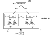
- FIG. 2 is a block diagram illustrating an overall configuration of an NR communication system 210 under discussion in 3GPP. It is a block diagram of DC by eNB and gNB connected to EPC. It is a block diagram of DC by gNB connected to NG core. It is a block diagram of DC by eNB and gNB connected to NG core. It is a block diagram of DC by eNB and gNB connected to NG core.
- FIG. 3 is a block diagram illustrating a configuration of a mobile terminal 202 illustrated in FIG. 2.
- FIG. 3 is a block diagram illustrating a configuration of a mobile terminal 202 illustrated in FIG. 2.
- FIG. 3 is a block diagram illustrating a configuration of a base station 203 illustrated in FIG. 2.
- FIG. 3 is a block diagram illustrating a configuration of an MME. It is a block diagram which shows the structure of 5GC.
- 5 is a flowchart illustrating an outline from a cell search to a standby operation performed by a communication terminal (UE) in an LTE communication system.
- FIG. 2 is a diagram illustrating an example of a cell configuration in an NR system.
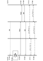
- FIG. 7 is a diagram illustrating an operation of switching a connection TRP of a UE according to the first embodiment.
- FIG. 6 is a diagram illustrating an operation of switching a connection TRP of a UE according to the first embodiment.
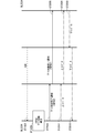
- FIG. 7 is a diagram illustrating an operation of switching a connection TRP by a UE connected to a plurality of TRPs in the first embodiment.
- FIG. 7 is a diagram illustrating an operation of switching a connection TRP by a UE connected to a plurality of TRPs in the first embodiment.
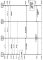
- FIG. 9 is a diagram illustrating an operation of adding a connection TRP in the UE according to the first embodiment.
- FIG. 9 is a diagram illustrating an operation of adding a connection TRP in the UE according to the first embodiment.
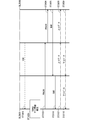
- FIG. 9 is a diagram illustrating an operation of adding a plurality of TRPs connected to a UE collectively in the first embodiment.
- FIG. 9 is a diagram illustrating an operation of adding a plurality of TRPs connected to a UE collectively in the first embodiment.
- FIG. 9 is a diagram illustrating an operation of releasing a connection TRP in the UE according to the first embodiment.
- FIG. 14 is a diagram illustrating an operation of switching a TRP for downlink communication in a UE according to a first modification of the first embodiment.
- FIG. 14 is a diagram illustrating an operation of switching a TRP for downlink communication in a UE according to a first modification of the first embodiment.
- FIG. 17 is a diagram illustrating another example of the operation of switching the TRP for downlink communication in the UE in Modification Example 1 of Embodiment 1.
- FIG. 14 is a diagram illustrating an operation of switching a TRP for downlink communication in a UE according to a first modification of the first embodiment.
- FIG. 17 is a diagram illustrating another example of the operation of switching the TRP for downlink communication in the UE in Modification Example 1 of Embodiment 1.
- FIG. 19 is a diagram illustrating another example of the operation of switching the TRP for downlink communication in the UE in Modification Example 1 of Embodiment 1.
- FIG. 19 is a diagram illustrating another example of the operation of switching the TRP for downlink communication in the UE in Modification Example 1 of Embodiment 1.
- FIG. 14 is a diagram illustrating an operation of switching a TRP for uplink communication in a UE according to a second modification of the first embodiment.
- FIG. 14 is a diagram illustrating an operation of switching a TRP for uplink communication in a UE according to a second modification of the first embodiment.
- FIG. 21 is a diagram illustrating another example of the operation of switching the TRP for uplink communication in the UE in Modification Example 2 of Embodiment 1.
- FIG. 19 is a diagram illustrating another example of the operation of switching the TRP for uplink communication in the UE in Modification 2 of Embodiment 1.
- FIG. 19 is a diagram illustrating another example of the operation of switching the TRP for uplink communication in the UE in Modification 2 of Embodiment 1.
- FIG. 19 is a diagram illustrating another example of the operation of switching the TRP for uplink communication in the UE in Modification 2 of Embodiment 1.
- FIG. 15 is a diagram illustrating an operation of applying role switching to recovery from an MCG failure according to the fourth embodiment.
- FIG. 21 is a diagram illustrating an operation of applying role switching for recovery from an MCG failure in a first modification of the fourth embodiment.
- FIG. 18 is a diagram illustrating the operation of multicarrier in SL according to the fifth embodiment.
- 20 is an example of a sequence for setting PSCCH and PSSCH at the same timing on a plurality of carriers according to Embodiment 5.
- 20 is an example of a sequence for setting PSCCH and PSSCH at the same timing on a plurality of carriers according to Embodiment 5.
- 20 is an example of a sequence for setting a PSCCH and a PSSCH at the same timing on a plurality of carriers according to a first modification of the fifth embodiment.
- FIG. 16 is a conceptual diagram for describing PC5-based V2V in the sixth embodiment.
- FIG. 18 is a conceptual diagram for describing a Uu-based V2V according to a sixth embodiment.
- FIG. 18 is a conceptual diagram for describing packet replication using PC5-based V2V and Uu-based V2V according to the sixth embodiment.
- FIG. 27 is a diagram illustrating packet replication in UE_tx according to the sixth embodiment.
- FIG. 27 is a diagram illustrating an example of packet duplication using PC5-based V2V communication and Uu-based V2V communication according to the sixth embodiment.
- 33 is a diagram illustrating an example of a sequence for setting a bearer for packet duplication according to Embodiment 6.
- FIG. 33 is a diagram illustrating an example of a sequence for setting a bearer for packet duplication according to Embodiment 6.
- FIG. 33 is a diagram illustrating an example of a sequence for setting a bearer for packet duplication according to Embodiment 6.
- FIG. 33 is a diagram illustrating an example of a sequence for setting a bearer for
- FIG. 33 is a diagram illustrating an example of packet duplication using PC5-based V2V communication and Uu-based V2V communication according to Modification Example 1 of Embodiment 6.
- FIG. 33 is a diagram illustrating an example of a sequence for setting a bearer for packet duplication according to Modification Example 1 of Embodiment 6.
- FIG. 33 is a diagram illustrating an example of a sequence for setting a bearer for packet duplication according to Modification Example 1 of Embodiment 6.
- FIG. 33 is a diagram illustrating an example of packet duplication using PC5-based V2V communication and Uu-based V2V communication according to Modification Example 2 of Embodiment 6.
- FIG. 33 is a diagram illustrating an example of a sequence for split bearer setting in Modification Example 2 of Embodiment 6.
- FIG. 33 is a diagram illustrating an example of a sequence for split bearer setting in Modification Example 2 of Embodiment 6.
- FIG. 2 is a block diagram illustrating an overall configuration of an LTE communication system 200 discussed in 3GPP.
- the radio access network is called an E-UTRAN (Evolved Universal Terrestrial Radio Access Network) 201.
- a mobile terminal device hereinafter referred to as “mobile equipment (User Equipment: UE)”
- UE Mobile Equipment
- base station E-UTRAN NodeB: eNB
- the “communication terminal device” includes not only a mobile terminal device such as a movable mobile phone terminal device but also a non-movable device such as a sensor.
- the “communication terminal device” may be simply referred to as “communication terminal”.
- a control protocol for the mobile terminal 202 for example, RRC (Radio Resource Control) and a user plane (hereinafter sometimes referred to as U-Plane), for example, PDCP (Packet Data Convergence Protocol), RLC (Radio Link Control), MAC (Medium) If Access @ Control) and PHY (Physical @ layer) terminate at the base station 203, the E-UTRAN includes one or more base stations 203.
- RRC Radio Resource Control
- U-Plane for example, PDCP (Packet Data Convergence Protocol), RLC (Radio Link Control), MAC (Medium) If Access @ Control) and PHY (Physical @ layer) terminate at the base station 203, the E-UTRAN includes one or more base stations 203.
- the control protocol RRC Radio Resource Control
- RRC connection management RRC connection management
- the states of the base station 203 and the mobile terminal 202 in RRC include RRC_IDLE and RRC_CONNECTED.
- RRC_IDLE PLMN (Public Land Mobile Network) selection, system information (System Information: SI) notification, paging, cell reselection (cell re-selection), mobility, and the like are performed.
- RRC_CONNECTED the mobile terminal has an RRC connection and can transmit and receive data to and from the network.
- handover Handover: HO
- measurement of a neighboring cell Neighbor @ cell
- the base station 203 is configured by one or a plurality of eNBs 207.
- a system including an EPC (Evolved @ Packet @ Core) as a core network and an E-UTRAN 201 as a radio access network is referred to as an EPS (Evolved @ Packet @ System).
- the EPC, which is a core network, and the E-UTRAN 201, which is a radio access network may be collectively referred to as a “network”.
- the eNB 207 includes a mobility management entity (Mobility @ Management @ Entity: MME), an S-GW (Serving @ Gateway), or an MME / S-GW unit including an MME and an S-GW (hereinafter may be referred to as "MME unit") 204 and Control information is communicated between the eNB 207 and the MME unit 204 via the S1 interface.
- MME unit Mobility Management Entity
- a plurality of MME units 204 may be connected to one eNB 207.
- the eNBs 207 are connected by an X2 interface, and control information is communicated between the eNBs 207.
- the MME unit 204 is a higher-level device, specifically, a higher-level node, and controls connection between the eNB 207 that is a base station and the mobile terminal (UE) 202.
- the MME unit 204 forms an EPC that is a core network.
- the base station 203 configures the E-UTRAN 201.
- the base station 203 may configure one cell or a plurality of cells. Each cell has a predetermined range as a coverage that can communicate with the mobile terminal 202, and performs wireless communication with the mobile terminal 202 within the coverage. When one base station 203 configures a plurality of cells, each cell is configured to be able to communicate with the mobile terminal 202.
- FIG. 3 is a block diagram showing an overall configuration of a 5G communication system 210 discussed in 3GPP.
- the wireless access network is referred to as NG-RAN (Next ⁇ Generation ⁇ Radio ⁇ Access ⁇ Network) 211.
- the UE 202 can wirelessly communicate with an NR base station device (hereinafter, referred to as an “NR base station (NG-RAN @ NodeB: gNB)”) 213, and transmits and receives signals by wireless communication.
- the core network is called a 5G core (5G @ Core: 5GC).
- a control protocol for the UE 202 for example, RRC (Radio Resource Control) and a user plane (hereinafter sometimes referred to as U-Plane), for example, SDAP (Service Data Adaptation Protocol), PDCP (Packet Data Convergence Protocol), RLC (Radio Link) If Control, MAC (Medium Access Control), and PHY (Physical Layer) terminate at the NR base station 213, the NG-RAN is configured by one or a plurality of NR base stations 213.
- RRC Radio Resource Control
- U-Plane for example, SDAP (Service Data Adaptation Protocol), PDCP (Packet Data Convergence Protocol), RLC (Radio Link)
- MAC Medium Access Control
- PHY Physical Layer
- the function of the control protocol RRC (Radio Resource Control) between the UE 202 and the NR base station 213 is the same as that of LTE.
- the states of the NR base station 213 and the UE 202 in RRC include RRC_IDLE, RRC_CONNECTED, and RRC_INACTIVE.
- RRC_IDLE and RRC_CONNECTED are the same as in the LTE system.
- RRC_INACTIVE performs notification of system information (System @ Information: SI), paging, cell reselection (cell @ re-selection), mobility, and the like while maintaining the connection between the 5G core and the NR base station 213. .
- the gNB 217 has an access / mobility management function (Access / Mobility / Management / Function: AMF), a session management function (Session / Management / Function: SMF), or UPF (User / Plane / Function), or AMF / SMF / UPF including AMF, SMF and UPF.
- AMF Access / Mobility / Management / Function
- SMF session management function
- UPF User / Plane / Function
- the NG interface is a general term for an N2 interface between gNB 217 and AMF, an N3 interface between gNB 217 and UPF, an N11 interface between AMF and SMF, and an N4 interface between UPF and SMF.
- a plurality of 5GC units 214 may be connected to one gNB 217.
- the gNBs 217 are connected by an Xn interface, and control information and / or user data is communicated between the gNBs 217.
- the NR base station 213 may configure one or a plurality of cells similarly to the base station 203. When one NR base station 213 forms a plurality of cells, each cell is configured to be able to communicate with the UE 202.
- the $ gNB 217 may be divided into a central unit (hereinafter sometimes referred to as a CU) 218 and a distributed unit (hereinafter sometimes referred to as a DU) 219.
- a central unit hereinafter sometimes referred to as a CU
- a distributed unit hereinafter sometimes referred to as a DU
- One CU 218 is configured in the gNB 217.
- One or a plurality of DUs 219 are configured in the gNB 217.
- the CU 218 is connected to the DU 219 by an F1 interface, and control information and / or user data is communicated between the CU 218 and the DU 219.
- FIG. 4 is a diagram showing a configuration of a DC including an eNB and a gNB connected to the EPC.
- a solid line indicates a U-Plane connection
- a broken line indicates a C-Plane connection.
- eNB 223-1 is a master base station
- gNB 224-2 is a secondary base station (this DC configuration may be referred to as EN-DC in some cases).
- FIG. 4 shows an example in which the U-Plane connection between the MME unit 204 and the gNB 224-2 is performed via the eNB 223-1. However, the U-Plane connection may be directly performed between the MME unit 204 and the gNB 224-2. Good.
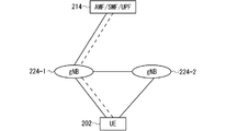
- FIG. 5 is a diagram showing a configuration of a DC using a gNB connected to an NG core.
- a solid line indicates a U-Plane connection
- a dashed line indicates a C-Plane connection.
- gNB224-1 is a master base station
- gNB224-2 is a secondary base station (this DC configuration may be referred to as NR-DC in some cases).
- FIG. 5 shows an example in which the U-Plane connection between the 5GC unit 214 and the gNB 224-2 is performed via the gNB 224-1, but the U-Plane connection may be directly performed between the 5GC unit 214 and the gNB 224-2. Good.
- FIG. 6 is a diagram showing a configuration of a DC including an eNB and a gNB connected to the NG core.
- a solid line indicates a U-Plane connection
- a broken line indicates a C-Plane connection.
- eNB 226-1 becomes a master base station
- gNB 224-2 becomes a secondary base station (this DC configuration may be referred to as NG-EN-DC in some cases).
- FIG. 6 illustrates an example in which the U-Plane connection between the 5GC unit 214 and the gNB 224-2 is performed via the eNB 226-1, but the U-Plane connection may be directly performed between the 5GC unit 214 and the gNB 224-2. Good.
- FIG. 7 is a diagram showing another configuration of the DC using the eNB and the gNB connected to the NG core.
- a solid line indicates a U-Plane connection
- a broken line indicates a C-Plane connection.
- gNB 224-1 is a master base station
- eNB 226-2 is a secondary base station (this DC configuration may be referred to as NE-DC).
- FIG. 7 illustrates an example in which the U-Plane connection between the 5GC unit 214 and the eNB 226-2 is performed via the gNB 224-1, but the U-Plane connection may be directly performed between the 5GC unit 214 and the eNB 226-2. Good.
- FIG. 8 is a block diagram showing a configuration of the mobile terminal 202 shown in FIG. The transmission process of the mobile terminal 202 shown in FIG. 8 will be described.
- control data from the protocol processing unit 301 and user data from the application unit 302 are stored in the transmission data buffer unit 303.
- the data stored in the transmission data buffer unit 303 is passed to the encoder unit 304 and subjected to encoding processing such as error correction.
- the data encoded by the encoder unit 304 is subjected to modulation processing by the modulation unit 305.
- Modulation section 305 may perform precoding in MIMO.
- FIG. 8 illustrates the case where the number of antennas is four, but the number of antennas is not limited to four.
- the receiving process of the mobile terminal 202 is executed as follows. Radio signals from the base station 203 are received by the antennas 307-1 to 307-4. The received signal is converted from a wireless reception frequency to a baseband signal by frequency conversion section 306, and demodulation processing is performed by demodulation section 308. Weight calculation and multiplication processing may be performed in demodulation section 308. The demodulated data is passed to the decoder unit 309, where decoding processing such as error correction is performed. Of the decoded data, control data is passed to the protocol processing unit 301, and user data is passed to the application unit 302. A series of processes of the mobile terminal 202 is controlled by the control unit 310. Therefore, the control unit 310 is connected to each of the units 301 to 309, although not shown in FIG. In FIG. 8, the number of antennas used for transmission and the number of antennas used for reception by mobile terminal 202 may be the same or different.
- FIG. 9 is a block diagram showing a configuration of base station 203 shown in FIG. The transmission process of the base station 203 shown in FIG. 9 will be described.
- EPC communication section 401 performs data transmission and reception between base station 203 and EPC (MME section 204 and the like).
- 5GC communication section 412 transmits and receives data between base station 203 and 5GC (5GC section 214 and the like).
- the other base station communication unit 402 transmits and receives data to and from another base station.
- EPC communication section 401, 5GC communication section 412, and other base station communication section 402 exchange information with protocol processing section 403, respectively. Control data from the protocol processing unit 403 and user data and control data from the EPC communication unit 401, the 5GC communication unit 412, and the other base station communication unit 402 are stored in the transmission data buffer unit 404.
- the data stored in the transmission data buffer unit 404 is passed to the encoder unit 405 and subjected to encoding processing such as error correction. There may be data directly output from the transmission data buffer unit 404 to the modulation unit 406 without performing the encoding process.
- the encoded data is subjected to a modulation process in a modulation unit 406.
- Modulation section 406 may perform precoding in MIMO.
- the modulated data is converted to a baseband signal and then output to the frequency conversion unit 407, where it is converted to a radio transmission frequency. Thereafter, a transmission signal is transmitted to one or more mobile terminals 202 from antennas 408-1 to 408-4.
- FIG. 9 illustrates the case where the number of antennas is four, but the number of antennas is not limited to four.
- the receiving process of the base station 203 is executed as follows. Radio signals from one or more mobile terminals 202 are received by antenna 408. The received signal is converted from a wireless reception frequency to a baseband signal by a frequency conversion unit 407, and demodulation processing is performed by a demodulation unit 409. The demodulated data is passed to a decoder unit 410, where decoding processing such as error correction is performed. Among the decoded data, the control data is passed to the protocol processing unit 403 or the 5GC communication unit 412 or the EPC communication unit 401 and the other base station communication unit 402, and the user data is sent to the 5GC communication unit 412, the EPC communication unit 401 and the other base station communication unit. It is passed to the station communication unit 402.
- a series of processes of the base station 203 is controlled by the control unit 411. Therefore, the control unit 411 is connected to each of the units 401 to 410, although omitted in FIG. In FIG. 9, the number of antennas used for transmission and the number of antennas used for reception by base station 203 may be the same or different.
- FIG. 9 is a block diagram showing the configuration of base station 203, but base station 213 may have a similar configuration. 8 and 9, the number of antennas of mobile terminal 202 and the number of antennas of base station 203 may be the same or different.
- FIG. 10 is a block diagram showing the configuration of the MME.
- FIG. 10 shows the configuration of MME 204a included in MME section 204 shown in FIG.
- PDN @ GW communication section 501 transmits and receives data between MME 204a and PDN @ GW.
- the base station communication unit 502 transmits and receives data between the MME 204a and the base station 203 using the S1 interface. If the data received from the PDN @ GW is user data, the user data is passed from the PDN @ GW communication unit 501 to the base station communication unit 502 via the user plane communication unit 503, and to one or more base stations 203. Sent. If the data received from the base station 203 is user data, the user data is passed from the base station communication unit 502 to the PDN @ GW communication unit 501 via the user plane communication unit 503, and transmitted to the PDN @ GW.
- control data is passed from the PDN @ GW communication unit 501 to the control plane control unit 505.
- control data is passed from the base station communication unit 502 to the control plane control unit 505.
- the control plane control unit 505 includes a NAS security unit 505-1, an SAE bearer control unit 505-2, an idle state (Idle @ State) mobility management unit 505-3, and the like, and a control plane (hereinafter, referred to as C-Plane). In some cases).
- the NAS security unit 505-1 performs security of a NAS (Non-Access @ Stratum) message and the like.
- the SAE bearer control unit 505-2 manages a bearer of SAE (System @ Architecture @ Evolution) and the like.
- the idle state mobility management unit 505-3 manages mobility in a standby state (idle state (Idle @ State); also referred to as LTE-IDLE state or simply idle), generates and controls a paging signal in the standby state, and is controlled by the idle state mobility management unit 505-3. Add, delete, update, search, and track area list management of one or more mobile terminals 202.
- the MME 204a distributes a paging signal to one or a plurality of base stations 203. Further, the MME 204a performs mobility control (Mobility @ control) in a standby state (Idle @ State). The MME 204a manages a tracking area (Tracking @ Area) list when the mobile terminal is in a standby state and in an active state (Active @ State). The MME 204a starts a paging protocol by transmitting a paging message to a cell belonging to a tracking area (tracking area: Tracking @ Area) where the UE is registered. The management of the CSG, the management of the CSG @ ID, and the management of the whitelist of the eNB 207 connected to the MME 204a may be performed by the idle state mobility management unit 505-3.
- FIG. 11 is a block diagram showing the configuration of 5GC.
- FIG. 11 shows the configuration of 5GC section 214 shown in FIG.
- FIG. 11 illustrates a case where the 5GC unit 214 illustrated in FIG. 5 includes the configuration of the AMF, the configuration of the SMF, and the configuration of the UPF.
- the Data @ Network communication unit 521 transmits and receives data between the 5GC unit 214 and the Data @ Network.
- Base station communication section 522 transmits and receives data via the S1 interface between 5GC section 214 and base station 203 and / or the NG interface between 5GC section 214 and base station 213.
- the user data is passed from the Data @ Network communication unit 521 to the base station communication unit 522 via the user plane communication unit 523, and one or more base stations 203 And / or transmitted to base station 213.
- the user data is passed from the base station communication unit 522 to the Data @ Network communication unit 521 via the user plane communication unit 523, and the Data @ Network is transmitted. Sent to
- the control data is passed from the Data ⁇ Network communication unit 521 to the session management unit 527 via the user plane control unit 523.
- the session management unit 527 passes the control data to the control plane control unit 525.
- the control data is passed from the base station communication unit 522 to the control plane control unit 525.
- the control plane control unit 525 passes the control data to the session management unit 527.
- the control plane control unit 525 includes a NAS security unit 525-1, a PDU session control unit 525-2, an idle state (Idle @ State) mobility management unit 525-3, and the like, and a control plane (hereinafter, also referred to as C-Plane). )).
- the NAS security unit 525-1 performs security of a NAS (Non-Access @ Stratum) message and the like.
- the PDU session control unit 525-2 manages a PDU session between the mobile terminal 202 and the 5GC unit 214, and the like.
- the idle state mobility management unit 525-3 manages mobility in a standby state (idle state (Idle State); RRC_IDLE state, or simply idle), generates and controls a paging signal in the standby state, It performs addition, deletion, update, search, and tracking area list management of one or more mobile terminals 202.
- Idle State Idle State
- RRC_IDLE state or simply idle
- # 5GC section 214 distributes a paging signal to one or a plurality of base stations 203 and / or base stations 213.
- the 5GC unit 214 performs mobility control (Mobility Control) in a standby state (Idle State).
- the 5GC unit 214 manages a tracking area (Tracking @ Area) list when the mobile terminal is in a standby state, an inactive state (Inactive @ State), and an active state (Active @ State).
- the 5GC unit 214 starts a paging protocol by transmitting a paging message to a cell belonging to a tracking area (tracking area: Tracking @ Area) in which the UE is registered.
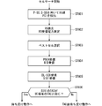
- FIG. 12 is a flowchart illustrating an outline from a cell search to a standby operation performed by a communication terminal (UE) in an LTE communication system.
- the communication terminal starts cell search, in step ST601, it uses the first synchronization signal (P-SS) and the second synchronization signal (S-SS) transmitted from the surrounding base stations to perform slot timing, frame Synchronize timing.
- P-SS first synchronization signal
- S-SS second synchronization signal
- synchronization signal (Synchronization @ Signal: SS).
- the synchronization signal (SS) is assigned a synchronization code corresponding to the PCI assigned to each cell on a one-to-one basis.
- the number of PCIs is 504. Synchronization is performed using the 504 types of PCI, and the PCI of the synchronized cell is detected (identified).
- a cell-specific reference signal which is a reference signal (reference signal: RS) transmitted from the base station for each cell, is detected for the synchronized cell.
- RS received power Reference / Signal / Received / Power: RSRP
- RS reference signal
- a code corresponding to one-to-one with PCI is used. By taking a correlation with the code, it can be separated from other cells. By deriving the RS code of the cell from the PCI identified in step ST601, it becomes possible to detect the RS and measure the received power of the RS.
- a cell with the best RS reception quality for example, a cell with the highest RS reception power, that is, a best cell, is selected from one or more cells detected up to step ST602.
- the base station receives the PBCH of the best cell and obtains BCCH as broadcast information.
- MIB Master @ Information @ Block
- the MIB information includes, for example, a DL (downlink) system bandwidth (also referred to as a transmission bandwidth configuration (transmission-bandwidth configuration: dl-bandwidth)), the number of transmission antennas, and an SFN (System-Frame-Number).
- step ST605 the DL-SCH of the cell is received based on the cell configuration information of the MIB, and the SIB (System Information Block) 1 in the broadcast information BCCH is obtained.
- SIB1 includes information on access to the cell, information on cell selection, and scheduling information on another SIB (SIBk; k ⁇ 2, an integer).
- SIB1 includes a tracking area code (Tracking Area Code: TAC).
- the communication terminal compares the TAC of SIB1 received in step ST605 with the TAC part of the tracking area identifier (Tracking @ Area ⁇ Identity: TAI) already held by the communication terminal.
- the tracking area list is also called a TAI list (TAI @ list).
- the TAI is identification information for identifying a tracking area, and is composed of MCC (Mobile Network Code), MNC (Mobile Network Code), and TAC (Tracking Area Code).
- MCC Mobile Network Code
- MNC Mobile Network Code
- TAC Track Area Code
- step ST605 If the TAC received in step ST605 is the same as the TAC included in the tracking area list as a result of the comparison in step ST606, the communication terminal enters a standby operation in the cell. By comparison, if the TAC received in step ST605 is not included in the tracking area list, the communication terminal transmits a TAU (Tracking Area Update) to the core network (Core Network, EPC) including the MME or the like through the cell.
- TAU Track Area Update
- EPC Core Network
- the best beam may be selected in addition to the best cell in step ST603.
- beam information for example, a beam identifier may be obtained.
- scheduling information of Remaining Minimum SI RMSI
- RMSI may be received in step ST605.
- a device constituting the core network performs tracking based on the identification number (UE-ID, etc.) of the communication terminal sent from the communication terminal together with the TAU request signal. Update the area list.
- the core network side device transmits the updated tracking area list to the communication terminal.
- the communication terminal rewrites (updates) the TAC list held by the communication terminal based on the received tracking area list. Thereafter, the communication terminal enters a standby operation in the cell.
- a cell configured by an eNB has a relatively wide range of coverage.
- a cell is configured to cover a certain area by a relatively wide coverage of a plurality of cells configured by a plurality of eNBs.
- the cell constituted by the eNB has a smaller coverage than the coverage of the cell constituted by the conventional eNB. Therefore, as in the conventional case, in order to cover a certain area, a large number of small cell eNBs are required as compared with the conventional eNB.
- a cell having relatively large coverage such as a cell configured by a conventional eNB
- a macro cell such as a cell configured by a conventional eNB
- an eNB configuring the macro cell is referred to as a “macro eNB”.
- a cell having relatively small coverage such as a small cell
- an eNB configuring the small cell is referred to as a “small eNB”.
- the macro eNB may be, for example, a “wide area base station (Wide Area Base Station)” described in Non-Patent Document 7.
- the small eNB may be, for example, a low power node, a local area node, a hot spot, or the like. Further, the small eNB is a pico eNB constituting a pico cell, a femto eNB constituting a femtocell, a HeNB, a RRH (Remote Radio Unit), an RRU (Remote Radio Unit), an RRE (Remote Radio Equipment) or an RN (Relay Node). There may be. Further, the small eNB may be a “local area base station (Local Area Base Station)” or a “home base station (Home Base Station)” described in Non-Patent Document 7.
- FIG. 13 shows an example of a cell configuration in NR.
- a narrow beam is formed and transmitted in different directions.
- the base station 750 performs transmission and reception with the mobile terminal using the beam 751-1 at a certain time. At other times, base station 750 transmits and receives to and from the mobile terminal using beam 751-2. Similarly, the base station 750 performs transmission and reception with the mobile terminal using one or more of the beams 751-3 to 751-8. By doing so, the base station 750 configures a wide range of cells.
- FIG. 13 shows an example in which the number of beams used by the base station 750 is eight, but the number of beams may be different from eight. Further, in the example shown in FIG. 13, the number of beams used simultaneously by base station 750 is one, but a plurality may be used.
- a plurality of TRPs (Transmission Reception Points) under the gNB may be used in the connection between the UE and the NR base station (hereinafter sometimes referred to as gNB).
- the base station 750 in FIG. 13 may be one of the TRPs under the control of the gNB.
- the TRP may be referred to as a transmitter-receiver.
- the plurality of TRPs described above may be asynchronous with each other. That is, the subframe boundaries of signals transmitted and received by each TRP may be different from each other. Said asynchronousness may be due to, for example, different backhaul delays.
- the gNB may perform transmission / reception using a plurality of TRPs to subordinate UEs at the same time, or may perform transmission / reception at a different timing for each TRP.
- the UE may transmit and receive the gNB to and from the plurality of TRPs simultaneously or at different timings.
- the UE may switch the transmission and reception destination TRP under the gNB.
- the UE uses the fact that the communication quality with other TRPs under the same gNB becomes better than the currently connected TRP, and uses the above-mentioned TRP with the improved communication quality as the connection destination TRP. May be switched.
- the gNB When connecting the UE to the TRP, for example, when switching the TRP to which the UE connects, the gNB instructs the UE to start random access processing.
- the indication may be notified using L1 / L2 signaling, for example, using PDCCH. That is, the random access process may be a PDCCH indication RA (PDCCH-order @ Random @ Access). This allows, for example, the base station to issue a quick random access instruction to the UE.
- PDCCH indication RA PDCCH-order @ Random @ Access
- the indication may be notified using MAC signaling. This allows, for example, the base station to put more information in the instruction.
- the indication may be notified using RRC signaling. This allows, for example, the base station to put more information in the instruction.
- the gNB may issue the instruction using the TRP to be switched (for example, the TRP before switching) or may use a TRP different from the switching target.
- the above-described instruction using a TRP different from the switching target may be used, for example, when the gNB communicates with the UE using a plurality of TRPs. Accordingly, for example, by using a TRP having a better communication quality than the TRP to be switched, it is possible to improve the reliability in the TRP switching instruction from the gNB to the UE.
- the instruction may be used for switching the SCell TRP.
- the gNB may transmit the switching instruction from a cell different from the SCell, for example, a PCell, a PSCell, or an SCell that can transmit a PDCCH.
- the instruction may include information on a cell in which TRP switching is performed (for example, a cell identifier).
- the gNB can issue a TRP switching instruction for a different cell.
- the indication may be used for switching the TRP between cells.
- the gNB may transmit the switching instruction from a cell before and after the switching, or may transmit the switching instruction from a cell different from the cell.
- the instruction may include information on a cell in which TRP switching between cells is performed (for example, an identifier of a cell before and / or after switching).
- the gNB can issue a TRP switching instruction between cells.
- the gNB may determine the TRP after switching using the measurement result notification from the UE.
- the gNB may determine a beam used for communication with the UE in the TRP. Thereby, for example, it is possible to ensure reliability in communication after TRP switching between the UE and the gNB.
- the measurement result in the UE may be the measurement result of the CSI-RS or the measurement result of the SS block.
- the gNB may determine the TRP after the switching by using the signal strength of the aforementioned signal received by the UE, for example, the RSRP.
- the gNB may determine the TRP after switching using the above-described signal reception quality, for example, RSRQ.
- the gNB may determine the TRP after switching using the signal-to-noise ratio.
- the gNB may instruct the UE to measure the above signal.
- the measurement instruction may be performed using RRC signaling.
- RRC signaling the MeasConfig described in Non-Patent Document 26 (3GPP @ TS38.331 @ V15.2.1) may be used, or another signaling may be used.
- the measurement instruction may be performed using MAC signaling, or may be performed using L1 / L2 signaling.
- a CSI report indication may be used, or other signaling may be used. This allows, for example, the gNB to promptly notify the UE of the measurement instruction.
- the gNB may include information on a TRP to be measured, for example, an identifier of the TRP, in the measurement instruction to the UE.
- the gNB may include information on the beam to be measured, for example, an identifier of the beam, in the measurement instruction.
- the gNB may include information on the number of measurement results reported from the UE to the gNB in the measurement instruction.
- the gNB may include a list of TRPs and / or beams to be measured in the measurement instruction.
- the information on the beam to be measured may be, for example, an identifier of a CSI-RS transmitted using the beam or an identifier of an SS block transmitted using the beam.
- the TRP identifier may be uniquely provided in the gNB, may be uniquely provided in the cell, or may be provided for each UE, for example, for each virtual cell identifier (Virtual ⁇ Cell ⁇ ID). .
- the TRP identifier may include a cell identifier, a UE identifier, or a virtual cell identifier.
- the identifier of the beam may be the same as the identifier of the TRP, or may be uniquely given in the TRP.
- the identifier of the beam may include the identifier of the TRP.
- the UE may report the measurement result to the gNB.
- the report may include information about the measured TRP.
- the report may include information about the beam in the TRP, for example, a CSI-RS identifier and / or an SS block identifier in the beam.
- the report may include received signal strength, received quality, and / or signal to noise ratio for the beam.
- the report may include measurements of the connected TRP and / or beam.
- the above-described connected TRP and / or beam may be a TRP and / or beam that is not included as a measurement target in the measurement instruction from the gNB to the UE.
- the UE may measure the connected TRP and / or beam even if it is not included in the measurement target of the measurement instruction. This allows, for example, the gNB to select the optimal connection destination TRP and / or beam including the TRP and / or beam to which the UE is currently connected, and as a result, it is possible to improve communication reliability.
- RRC signaling may be used for reporting the above measurement result.
- MeasurementReport described in Non-Patent Document 26 3GPP @ TS38.331 @ V15.2.1
- MAC signaling may be used, and L1 / L2 signaling may be used.
- CSI reporting (CSI @ reporting) may be used. The above-mentioned CSI report may be included in the PUCCH or may be included in the PUSCH.
- the above-mentioned CSI report may be a periodic CSI report, a semi-persistent CSI report, or an aperiodic CSI report.
- RACH may be used and SRS may be used.
- information on the measurement result may be included as a sequence of RACH preambles.
- information on the TRP and / or the beam to be measured may be included as the time and / or frequency resource of the SRS, or the information on the measurement result may be the time and / or frequency of the SRS. It may be included as a resource, may be included as an SRS sequence, or may be the combination described above.
- the identifier of the beam may be unique within the gNB.
- the gNB may report information on the correspondence between the TRP and the beam to UEs under its control, or may individually notify the UE.
- the UE may include the beam identifier in the report of the measurement result. This makes it possible to reduce the amount of signaling in the report, for example.
- RRC dedicated signaling may be used
- MAC signaling may be used
- L1 / L2 signaling may be used.
- the identifier of the beam may be unique within the TRP.
- the UE may notify the gNB including the identifier of the TRP in the report of the measurement result. Thereby, for example, it is possible to increase the number of beams that can be supported in one TRP, and as a result, it is possible to improve flexibility in the communication system.
- the gNB may notify the UE of information on the identifier of the TRP or may individually notify the UE.
- PBCH may be used
- RMSI Remaining ⁇ System ⁇ Information
- RRC dedicated signaling may be used
- MAC signaling may be used
- L1 / L2 signaling may be used.
- the UE may notify the gNB of the candidate for the TRP after the switching.
- the gNB may determine the TRP after switching from the candidates.
- the gNB may notify the UE of the determined TRP.
- the notification may be, for example, the same method as the method in which the gNB determines the TRP after switching using the measurement result notification from the UE.
- the gNB can select the TRP after switching using the load status of the TRP, and as a result, the communication system can be operated efficiently.
- the UE may measure the peripheral TRP including the connection destination TRP.
- the measurement may be performed using a measurement instruction from the gNB, or may be performed without the measurement instruction.
- the measurement may be performed periodically, or may be performed when a predetermined condition is satisfied.
- the condition may be, for example, a condition relating to communication quality with a connected TRP.
- a threshold value related to a reception error rate for example, BER or BLER may be used
- a threshold value related to RSRP of RS transmitted from the TRP may be used. May be used, a threshold value for RSRQ may be used, and a threshold value for SINR may be used.
- the RS may be, for example, a DMRS, a CSI-RS, or a PTRS.
- An SS block may be used instead of the RS.
- the condition may be, for example, that the UE starts the measurement when the communication quality of the UE is equal to or less than the above-described threshold value or less. Thus, for example, it is possible to reduce the amount of signaling between the UE and the gNB while ensuring the communication quality between the UE and the gNB.
- the threshold value described above may be determined in advance by a standard, or may be reported or notified from the gNB to the UE.
- a standard for example, RRC signaling may be used, MAC signaling may be used, or L1 / L2 signaling may be used.
- RSRP of a signal received from a peripheral TRP may be used, RSRQ may be used, SINR may be used, or the combination described above may be used.
- RSRQ may be used
- SINR may be used, or the combination described above may be used.
- a predetermined number of TRPs and / or beams may be used as the candidates in the descending order of RSRP, and TRPs and / or beams having an RSRP equal to or more than a predetermined threshold value may be used as the candidates.
- up to a predetermined number of TRPs and / or beams may be set as the candidates in the descending order of the RSRP, RSRQ, or SINR. This can prevent, for example, an increase in the signaling amount between the UE and the gNB.
- at least one TRP and / or beam may be considered as the candidate, regardless of whether it is above or above a predetermined threshold.
- the above-described threshold used for selecting the candidate may be the same as or different from the threshold used for starting measurement of the UE.
- a method of determining a threshold used for selecting the candidate may be determined in the same manner as the threshold used for starting measurement of the UE, or may be notified or notified to the UE in a similar manner. This makes it possible, for example, to avoid complexity in the design of the communication system.
- the predetermined number described above may be determined by a standard, or may be reported or notified from the gNB to the UE.
- RRC signaling may be used
- MAC signaling may be used
- L1 / L2 signaling may be used.
- the UE may determine the TRP after switching.
- the UE may measure, for example, peripheral TRPs including the connection destination TRP.
- the measurement may be performed using a measurement instruction from the gNB, may be performed periodically without the measurement instruction, or may be performed using a TRP switching instruction from the gNB to the UE. May be.
- the TRP switching instruction from the gNB to the UE there may be no information on the switching destination TRP.
- the UE may notify the gNB of information on the determined TRP.
- the indication may include information about the beam in the TRP.
- the information about the beam may be, for example, a CSI-RS identifier and / or an SS block identifier for the beam.
- RRC signaling may be used
- MAC signaling may be used
- L1 / L2 signaling may be used, or the above-described combination may be used.
- the UE can quickly notify the base station of the information on the determined TRP to the gNB.
- the UE may determine the TRP after the switch using the signal strength of the above-mentioned signal received by the UE, for example, the RSRP.
- the UE may determine the TRP after the switching by using the reception quality of the signal, for example, the RSRQ.
- the UE may determine the TRP after the switch using the signal-to-noise ratio. Thereby, for example, it is possible to improve the reliability of communication between the UE and the gNB after TRP switching.
- the following (1) to (14) are disclosed as examples of information included in the random access start instruction from the gNB to the UE.
- the information (1) described above may be, for example, an identifier of a TRP of a connection destination, or may be information on a beam used by the TRP.
- the beam information for example, information on the SS block may be used, information on the CSI-RS may be used, or both of the above may be used.
- the UE can quickly acquire the beam of the connection destination.
- the information on the SS block described above may be, for example, an identifier of the SS block.
- the information on the CSI-RS described above may be, for example, an identifier of a CSI-RS resource.
- the information of the above (1) may be one or plural.
- the information of the above (1) may be a plurality.
- one or more TRPs may be connected. Thereby, for example, it is possible to reduce the amount of signaling from the base station to the UE when a plurality of TRPs and / or beams are added as a connection destination of the UE.
- the information of (1) above may include information on the number of TRPs and / or beams at the connection destination.
- the UE can quickly acquire the number of TRPs and / or beams to be connected to, and as a result, the UE can quickly execute the TRP and / or beam connection processing.
- the information in (1) above may be only information on the number of TRPs and / or beams at the connection destination.
- the UE may determine the above-mentioned number of TRPs and / or beams as a new connection destination from TRPs and / or beams that can be transmitted and received.
- the UE may use the strength of the signal received from the TRP and / or the beam, or may use the PRACH transmission timing for the TRP and / or the beam in determining the new destination TRP and / or the beam, Other indices (eg, the signal-to-noise ratio of the received signal) may be used.
- the UE can communicate with the base station using the TRP and / or the beam with high communication quality, and as a result, the communication quality between the UE and the base station can be improved. Also, for example, the UE can use the TRP and / or the beam with the early PRACH transmission timing, and as a result, the TRP and / or the beam can be quickly switched and / or added in the UE.
- the UE may use this information to determine whether to switch or add a TRP to which the UE connects. For example, if the information in (2) above indicates that the connection is not broken, the UE may add a TRP to be connected using the content. Thus, for example, the UE can quickly determine whether to add or switch the connection destination TRP.
- the above information (3) may be the same as the above information (1), for example.
- the information may be information on a TRP and / or a beam before switching, for example, a TRP and / or a beam to be disconnected from a UE, or may include information on the number of the TRP and / or a beam. Good. Thereby, for example, an effect similar to the above (1) can be obtained.
- the information of the above (3) may be notified from the gNB to the UE by signaling different from the random access start instruction.
- the information may be signaled from the gNB to the UE as a TRP release indication.
- the gNB does not need to transmit a random access start instruction to the UE, and as a result, the signaling amount between the gNB and the UE can be reduced.
- the TRP release instruction may be, for example, L1 / L2 signaling. This allows, for example, a quick notification from the gNB to the UE.
- the signaling may be MAC signaling or RRC signaling. Thereby, for example, a lot of information can be notified.
- the information of (4) above may be the same as the information of (1), for example.
- the information may be information on a TRP and / or a beam for maintaining a connection with the UE, or may include information on the number of the TRP and / or the beam. Thereby, for example, an effect similar to the above (1) can be obtained.
- the information of the above (4) may be notified from the gNB to the UE by signaling different from the random access start instruction.
- the information of the above (4) may be included in the above-mentioned TRP release instruction.
- the information of (5) above may be the same as the information of (1), for example.
- the information may be information on TRPs and / or beams that are candidates for connection with the UE.
- the UE may select a TRP and / or beam to be newly connected from among the TRPs and / or beams to be connected included in the above (5).
- the UE may select the number of TRPs and / or beams included in the above (1).
- the UE may use the method disclosed with respect to the above information (1) in determining a new connection destination TRP and / or beam.
- the UE can select a TRP and / or a beam having a high communication quality and / or an early PRACH transmission timing.
- communication quality between the UE and the base station can be improved.
- the information in (6) above may be, for example, information on the timing at which the UE should transmit the PRACH to the TRP and / or beam after switching.
- the UE may transmit the PRACH to the connected TRP and / or beam using the information. As a result, the UE can quickly execute the random access process for the TRP and / or beam of the connection destination.
- the information of the above (6) may be information indicating the correspondence between the SS block and the PRACH transmission enable timing (for example, the PRACH occasion (occasion)) in the TRP after switching.
- the SS block in the information may be, for example, an SS block index (SSB index).
- the UE may not acquire the system information in the TRP after switching by acquiring the information. This allows, for example, the UE to quickly execute TRP switching.
- the UE may acquire the information of (6) from the broadcast information of the gNB.
- the broadcast information may be transmitted from, for example, the TRP of the connection destination. Thereby, for example, it is possible to reduce the signaling amount of the random access instruction from the gNB to the UE.
- the preamble included in the above information (7) may be a preamble individually given to the UE.
- the UE may start random access processing with a newly connected TRP and / or beam using the notified information of the RA preamble. As a result, random access processing between the UE and the gNB can be quickly performed.
- the preamble included in the information of the above (7) may be uniquely provided in the TRP, or may be uniquely provided in each beam used by the TRP. As a result, for example, it is possible to prevent the depletion of the RA preamble, and as a result, it is possible to increase the number of storable UEs.
- the preamble included in the information of the above (7) may be uniquely given in the gNB.
- the TRP and / or beam to which the UE should connect may be uniquely determined from the preamble information included in the above (7). Thereby, for example, it is possible to reduce the signaling amount in the random access instruction from the base station to the UE.
- the information of the above (7) may be information indicating the correspondence between the SS block and the preamble in the TRP after switching.
- the SS block in the information may be, for example, an SS block index (SSB index).
- the UE may not acquire the system information in the TRP after switching by acquiring the information. This allows, for example, the UE to quickly execute TRP switching.
- the RA preamble used by the UE for connection with the gNB, the RA preamble may be uniquely determined from the information on the above (1). Thereby, for example, it is possible to reduce the signaling amount in the random access instruction from the base station to the UE.
- the information in (8) above may be, for example, information measured by the gNB, or information measured by the UE and reported to the gNB.
- the UE may not perform the random access process on the TRP after the switching, for example, when the TRP before the switching and the TRP after the switching are synchronized using the information of (8) described above. Thereby, for example, TRP switching in the UE can be quickly performed.
- the information (9) described above may be, for example, information on a difference in frame timing between the TRP before switching and the TRP after switching.
- the information may be, for example, one measured by the gNB, or one measured by the UE and reported to the gNB.
- the UE may transmit the PRACH at the PRACH reception timing of the TRP after switching using the information.
- the UE does not need to wait for the SS burst from the TRP after switching, and as a result, the UE can quickly execute RACH transmission to the TRP after switching.
- the information (10) described above may be, for example, information on a difference between a backhaul delay in a TRP before switching and a backhaul delay in a TRP after switching.
- the information may be, for example, one measured by the gNB, or one measured by the UE and reported to the gNB.
- the UE may perform PRACH transmission on the TRP after switching using the information. Thereby, for example, it is possible to reduce the value of TA (Timing ⁇ ⁇ ⁇ ⁇ Advance) in the RA response, and as a result, it is possible to reduce the processing amount of the UE after receiving the RA response.
- TA Timing ⁇ ⁇ ⁇ ⁇ Advance
- the information in (11) above may be, for example, the identifier of the primary TRP.
- the above-mentioned information (11) may be an identifier indicating whether or not the primary TRP is switched, or may be an identifier indicating whether the switched TRP is the primary TRP.
- the gNB and the UE may determine a TRP other than the TRP as a secondary TRP.
- the UE may switch the primary TRP using the information on the above (11). Thus, for example, when the primary TRP is set for the UE, the UE can quickly switch the primary TRP.
- the information of (12) above may be, for example, an identifier of a TRP transmitting the primary PDCCH and / or the secondary PDCCH.
- the above-mentioned TRP identifier may be one or plural. There may be no identifier of the TRP transmitting the secondary PDCCH. When there is no TRP identifier for transmitting the secondary PDCCH, the secondary PDCCH may not be transmitted.
- the information of the above (12) may not include the identifier of the primary TRP.
- the primary PDCCH may be transmitted from at least the primary TRP.
- the UE may perform the receiving operation of the primary PDCCH and / or the secondary PDCCH using the information of (12) described above. The UE may stop the receiving operation for the TRP that is not included in the information of (12). Thereby, for example, power consumption in the UE can be reduced.
- the information in (13) above may be, for example, scheduling information for transmission and reception performed by the UE with the TRP after switching.
- the UE may transmit and receive signals and / or data to and from the TRP after switching using the information of (13) described above.
- the UE can quickly execute data transmission and reception after synchronization is established with the TRP after switching.
- the information may be included in the RA response.
- the UE can quickly execute data transmission and reception after establishing synchronization with the TRP after switching, and can reflect the communication environment of the UE at the time of TRP switching in scheduling. For this reason, the transmission and reception efficiency in the communication system can be improved.
- the information may be included in both the random access instruction and the RA response.
- information on periodic and / or semi-persistent scheduling may be included in the random access indication
- information on dynamic scheduling may be included in the RA response.
- the UE can quickly execute data transmission and reception after establishing synchronization with the TRP after switching, and can reduce the amount of signaling in the RA response.
- the information of (13) above may include information of PDSCH scheduled by the primary PDCCH, may include information of PUCCH, may include information of PUSCH, and may include information of SRS. Information may be included.
- the PDSCH, PUCCH, PUSCH, and / or SRS information described above may include TRP information for transmitting and receiving the channel and / or signal, for example, a TRP identifier.
- a plurality of TRPs may be included in the PDSCH, PUCCH, PUSCH, and / or SRS information described above.
- the UE may transmit and receive the channel and / or the signal using the information of (13) described above. This enables, for example, flexible scheduling in communication using a plurality of TRPs.
- the UE performs random access with the connection destination TRP by using a random access instruction from the gNB.
- the UE may start the random access process using the frame timing of the TRP after switching.
- the UE may establish downlink synchronization with the TRP after switching using the random access instruction.
- the UE may establish the downlink synchronization by using the reception of the SS block transmitted from the connection destination TRP. This makes it possible to prevent interference in the TRP after switching, for example.
- the UE may obtain downlink synchronization with the connection destination TRP in advance. For example, the UE may maintain the downlink synchronization established at the time of measuring the connection destination TRP.
- the above-described measurement may be, for example, the measurement of the CSI-RS or the measurement of the SS block. Thereby, for example, the UE can quickly transmit the PRACH to the gNB.
- the UE may start the random access process using the frame timing of the TRP before switching.
- the UE may derive the frame timing of the post-switch TRP using the information on the above (9).
- the UE may transmit the PRACH at the PRACH reception timing of the TRP after switching using the derived frame timing.
- the UE does not need to wait for the SS burst from the TRP after switching, and as a result, the UE can quickly execute RACH transmission to the TRP after switching.
- the UE may acquire system information from the gNB in the random access process.
- the UE may obtain a PRACH transmission timing (eg, a PRACH occasion) using the system information. Accordingly, for example, the gNB does not need to individually notify the information of the above (6) to the UE, and as a result, the amount of signaling between the gNB and the UE can be reduced.
- the UE does not have to acquire the system information from the gNB in the random access process.
- the gNB may notify the UE of the information of the above (6).
- the UE may acquire the PRACH transmission timing (for example, the PRACH occasion) using the information of (6) described above.
- the UE does not need to acquire system information, and as a result, the UE can quickly perform random access.
- the gNB may notify the UE of the information of the above (7) in advance.
- the UE may perform a random access process using the preamble included in the information (7). This makes it possible to prevent, for example, collision with another UE in random access, and as a result, the UE can execute random access quickly.
- the correspondence between the SS block and the PRACH transmittable timing may be uniquely given in the TRP.
- the correspondence may be different between TRPs.
- the allocation of the PRACH transmittable timing in the gNB can be flexibly performed.
- the correspondence between the SS block and the PRACH transmittable timing may be uniquely given in a cell. That is, the correspondence may be unique among the TRPs. This makes it possible, for example, to avoid complexity in the communication system.
- System information transmitted from the gNB may be different for each TRP of the transmission source.
- the system information may be only system information on the TRP.
- the system information on the TRP may include, for example, the correspondence between the above-mentioned SS block and the PRACH transmission enable timing in the TRP.
- the amount of system information transmitted by the gNB can be reduced.
- the system information transmitted from the gNB may include system information on all or a part of the TRPs under the gNB.
- the system information on the TRP may include, for example, the correspondence between the above-mentioned SS block and the PRACH transmission enable timing in the TRP.
- the UE can acquire the system information used in the switching destination TRP at the time of the TRP switching, so that the UE can quickly execute the TRP switching.
- the UE may stop transmission / reception of signals and / or data via the TRP before switching using the random access instruction from the gNB.
- the UE may resume transmission and reception of signals and / or data via the switched TRP using the RA response received from the gNB via the switched TRP.
- gNB the same applies to gNB.
- it is possible to prevent interference with the TRP before and / or after switching during TRP switching.
- the UE may transmit a HARQ response to the random access instruction from the gNB to the TRP before switching.
- the transmission of the HARQ response may be performed, for example, when the random access instruction is performed using RRC signaling or MAC signaling.
- the UE can notify the HARQ-Nack to the gNB, and the gNB notifies the UE of the HARQ-Nack.
- the random access instruction can be retransmitted.
- the UE may transmit a HARQ response to downlink data from the gNB to the TRP before switching.
- the transmission of the HARQ response to the TRP before switching may be performed, for example, before the transmission of the HARQ response to the above-described random access instruction. Accordingly, for example, even when the HARQ decoding result of the downlink data in the UE becomes NG, the UE can notify the gNB of the HARQ-Nack, and the gNB can The downlink data can be retransmitted.
- the UE may transmit a HARQ response to downlink data from the gNB to the TRP after switching.
- the transmission of the HARQ response to the TRP after the switching may be performed, for example, after the transmission of the HARQ response to the above-described random access instruction.
- the UE may suspend the HARQ response until the timing of transmitting the PRACH to the TRP after switching. Thereby, for example, the same effect as described above can be obtained.
- the UE may receive the HARQ response to the uplink data to the gNB from the TRP before the switching.
- the reception of the HARQ response from the TRP before switching may be performed, for example, before the transmission of the HARQ response to the above-described random access instruction.
- the UE can receive the HARQ-Nack from the gNB, and the UE sends the HARQ-Nack to the gNB.
- Uplink data can be retransmitted.
- the UE may receive the HARQ response to the uplink data to the gNB from the switched TRP.
- the reception of the HARQ response from the TRP after the switching may be performed, for example, before the transmission of the HARQ response to the above-described random access instruction.
- the UE may suspend the reception of the HARQ response until after the timing of receiving the RA response from the TRP after switching. Thereby, for example, the same effect as described above can be obtained.
- the UE does not have to assume downlink data reception after the random access instruction or after the random access instruction.
- the UE may not receive downlink data after the random access instruction or after the random access instruction.
- Downlink data transmission to the UE may be resumed after an RA response from the TRP after switching. This makes it possible, for example, to avoid design complexity in the communication system.
- the UE may not perform uplink data transmission after the random access instruction or after the random access instruction. Uplink data transmission from the UE may be resumed after the RA response from the TRP after switching. This makes it possible, for example, to avoid design complexity in the communication system.
- the UE may reselect or determine the connection destination TRP.
- the above operation may be performed, for example, when the UE has failed in the process of switching to the TRP after switching.
- the failure of the switching process may be, for example, a failure of a random access process or a failure of capturing an SS block.
- the UE may notify the gNB of the reselection or redetermination of the connection destination TRP, including information indicating that the TRP switching process has failed. Thereby, for example, it is possible to avoid a communication disabled state between the gNB and the UE when the TRP switching process fails. As a result, the robustness of the communication system can be improved.
- FIGS. 14 and 15 are diagrams illustrating an operation of switching the connection TRP of the UE.
- FIG. 14 and FIG. 15 are connected at the position of the boundary line BL1415.
- the TRP connected to the UE switches from TRP # 1 to TRP # 2.
- 14 and 15 show an operation example in which the UE measures the CSI-RS, and the gNB determines the connection destination TRP using the measurement result.
- Step ST1401 shows data transmission and reception between UE and TRP # 1
- step ST1402 shows data transmission and reception between TRP # 1 and gNB.
- steps ST1405 and ST1406 shown in FIG. 14 gNB instructs UE to measure CSI-RS via TRP # 1.
- Step ST1405 shows a measurement instruction from gNB to TRP # 1
- step ST1406 shows a measurement instruction from TRP # 1 to the UE.
- the measurement instruction shown in steps ST1405 and ST1406 may be performed by RRC signaling, may be performed by MAC signaling, or may be performed by L1 / L2 signaling.
- Step ST1410 and ST1411 shown in FIG. 14, TRP # 1 and TRP # 2 transmit a CSI-RS to the UE.
- Step ST1410 shows CSI-RS transmission from TRP # 1
- step ST1411 shows CSI-RS transmission from TRP # 2.
- the UE receives the CSI-RS shown in Steps ST1410 and ST1411, and measures the signal.
- Step ST1415 indicates a measurement result notification from the UE to TRP # 1
- step ST1416 indicates a measurement result notification from TRP # 1 to the gNB.
- the measurement result notification shown in steps ST1415 and ST1416 may be performed by RRC signaling, may be performed by MAC signaling, or may be performed by L1 / L2 signaling.
- step ST1420 shown in FIG. 14 the gNB determines to switch the TRP of the connection destination of the UE from TRP # 1 to TRP # 2 using the measurement result in step ST1416.
- Step ST1425 and ST1426 shown in FIG. 14 the gNB instructs the UE to start RACH via TRP # 1.
- Step ST1425 shows the instruction from gNB to TRP # 1
- step ST1426 shows the instruction from TRP # 1 to the UE.
- the indication may be transmitted using the PDCCH.
- the instruction includes information indicating switching from TRP # 1 to TRP # 2.
- the instruction may include information on the RA preamble.
- the UE releases the connection with TRP # 1 in step ST1427 shown in FIG. 15 using step ST1426.
- step ST1428 shown in FIG. 15 an SS block is transmitted from TRP # 2 to the UE, and in step ST1429 shown in FIG.
- the UE uses the SS block in step ST1428 to perform downlink synchronization with TRP # 2. To establish. After transmitting the instruction in Step ST1425, the gNB stops the downlink data transmission via the TRP # 1. After receiving the instruction in Step ST1426, the UE stops uplink data transmission via TRP # 1.
- the UE transmits the PRACH to the gNB via TRP # 2.
- Step ST1430 shows PRACH transmission from UE to TRP # 2
- step ST1431 shows PRACH transmission from TRP # 2 to gNB.
- the RA preamble in the PRACH transmission may be the RA preamble included in step ST1426, or may be different.
- Step ST1435 and ST1436 shown in FIG. 15 the gNB notifies the UE of a random access response via TRP # 2.
- Step ST1435 indicates a random access response notification from the gNB to TRP # 2
- step ST1436 indicates a random access response notification from TRP # 2 to the UE.
- the UE establishes uplink synchronization with TRP # 2 using the response.
- the gNB After transmitting the instruction in Step ST1435, the gNB starts downlink data transmission via TRP # 2.
- the UE starts uplink data transmission via TRP # 2.
- steps ST1440 and ST1441 shown in FIG. 15 transmission / reception of uplink / downlink data via TRP # 2 is performed between the UE and the gNB.
- Step ST1440 shows data transmission and reception between UE and TRP # 2
- step ST1441 shows data transmission and reception between TRP # 2 and gNB.
- the CSI-RS is measured is shown, but the SS block may be measured.
- the gNB may instruct the UE to measure the SS block in steps ST1405 and ST1406.
- the UE may notify the gNB of the measurement result of the SS block in Steps ST1415 and ST1416.
- the UE can directly use the signal used for synchronization of the measurement target TRP as the measurement target, so that quick measurement can be performed in the UE.
- FIGS. 14 and 15 show an example in which the TRP # 1 connection release in the UE is performed before the PRACH transmission in step ST1430, as shown in step ST1427.
- TRP # 1 connection release may be performed after the random access response in step ST1436.
- the example has been described in which the UE establishes uplink synchronization after the random access response in step ST1436, but the UE may transmit a random access message 3 to the gNB.
- the gNB may transmit a random access message 4 to the UE.
- the above-described transmission and reception of the random access message 3 and the message 4 may be applied, for example, when the UE uses an RA preamble different from the RA preamble notified from the gNB in step ST1431. This enables, for example, random access on the assumption of collision in TRP switching between the UE and the gNB, and as a result, the number of UEs accommodated in the gNB can be increased.
- the UE autonomously starts a random access process. That is, the UE may start the random access process without the above-described random access instruction transmitted from the gNB.
- the above-mentioned random access instruction may be, for example, a TRP switching instruction.
- the gNB may not send a rejection response to the autonomous random access process by the UE.
- the base station instructing the UE to switch the TRP and / or release the TRP may be performed as an operation of rejecting the autonomous random access processing in the gNB.
- the gNB may send a rejection response to the autonomous random access process performed by the UE.
- the response may be, for example, that no RA response is made during a predetermined period. This makes it possible, for example, to avoid design complexity in the communication system.
- the random access processing described above may be random access without contention (Contention-free @ RandomAccess). That is, the UE may use the RA preamble allocated in advance from the gNB. Thereby, for example, the random access processing can be completed quickly.
- the above-described random access processing may be collision-based random access (Contention-based @ Random @ Access). Thereby, for example, it is possible to prevent the resource of the RA preamble from being depleted in the gNB, and as a result, it is possible to increase the number of accommodated UEs in the gNB.
- the method disclosed in the first embodiment may be applied to switching of TRP when UE performs transmission / reception with a plurality of TRPs.
- one TRP may be switched, or a plurality of TRPs may be switched.
- the TRPs may be switched one by one, or a plurality of TRPs may be switched at a time. For example, by performing switching of a plurality of TRPs at once, TRP switching can be quickly performed.
- the UE may notify the gNB of information on a combination of TRPs with which the UE can perform simultaneous communication.
- the information may be information on a combination of beams with which the own UE can perform simultaneous communication.
- the UE may notify the information by including it in the signaling of the measurement result report described above, or may notify the UE using different signaling.
- the gNB may use the information to determine the switching destination TRP in the UE.
- the gNB can easily determine the TRP with which the UE can perform simultaneous communication.
- the communication rate between the UE and the gNB can be improved, and the reliability between the UE and the gNB can be improved.
- a TRP used for PCell communication may be used, a TRP used for PSCell communication may be used, or a SCell capable of PDCCH transmission may be used.
- a TRP used for communication may be used.
- FIGS. 16 and 17 are diagrams showing an operation in which a UE connected to a plurality of TRPs switches connection TRPs.
- FIG. 16 and FIG. 17 are connected at the position of the boundary line BL1617.
- FIGS. 16 and 17 show an operation example in which the UE measures the CSI-RS and the gNB determines the connection destination TRP using the measurement result.
- the same parts as those in FIGS. 14 and 15 are denoted by the same reference numerals, and the common description will be omitted.
- Steps ST1401 and ST1402 in FIG. 16 are the same as those in FIG.
- steps ST1501 and ST1502 shown in FIG. 16 transmission / reception of uplink / downlink data via TRP # 2 is performed between the UE and the gNB.
- Step ST1501 shows data transmission and reception between UE and TRP # 2
- step ST1502 shows data transmission and reception between TRP # 2 and gNB.
- Steps ST1405 to ST1411 in FIG. 16 are the same as those in FIG.
- TRP # 3 transmits a CSI-RS to the UE.
- the UE receives the CSI-RS shown in Steps ST1410, ST1411, and ST1503, and measures the signal.
- Steps ST1415 and ST1416 in FIG. 16 are the same as those in FIG.
- step ST1504 shown in FIG. 16 the gNB determines to switch the TRP of the connection destination of the UE from TRP # 1, # 2 to TRP # 1, # 3 using the measurement result of step ST1416.
- Step ST1505 shows the instruction from gNB to TRP # 1
- step ST1506 shows the instruction from TRP # 1 to the UE.
- the indication may be transmitted using the PDCCH.
- the UE releases the connection with TRP # 2 in step ST1527 shown in FIG. 17 using step ST1506.
- Step ST1525 and ST1526 shown in FIG. 17 the gNB starts RACH instruction to the UE via TRP # 1.
- Step ST1525 indicates the instruction from the gNB to TRP # 1
- step ST1526 indicates the instruction from TRP # 1 to the UE.
- the indication may be transmitted using the PDCCH.
- the instruction includes information indicating the addition of TRP # 3.
- the instruction may include information on the RA preamble.
- the UE starts the operation of receiving the SS block transmitted from TRP # 3 to the UE in Step ST1528 illustrated in FIG. 17 using Step ST1526.
- Step ST1529 shown in FIG. 17 the UE establishes downlink synchronization with TRP # 3 using the SS block in Step ST1528.
- the UE transmits the PRACH to the gNB via TRP # 3.
- Step ST1507 shows PRACH transmission from UE to TRP # 3
- step ST1508 shows PRACH transmission from TRP # 3 to gNB.
- the RA preamble in the PRACH transmission may be the RA preamble included in step ST1526, or may be different.
- Step ST1509 indicates a random access response notification from the gNB to TRP # 3
- step ST1510 indicates a random access response notification from TRP # 3 to the UE.
- the UE establishes uplink synchronization with TRP # 3 using the response.
- the gNB After transmitting the response in Step ST1509, the gNB starts downlink data transmission via TRP # 3.
- the UE starts uplink data transmission via TRP # 3.
- steps ST1511, ST1512 shown in FIG. 17 transmission / reception of uplink / downlink data via TRP # 1 is performed between the UE and the gNB.
- Step ST1511 shows data transmission and reception between UE and TRP # 1
- step ST1512 shows data transmission and reception between TRP # 1 and gNB.
- steps ST1513 and ST1514 shown in FIG. 17 transmission / reception of uplink / downlink data is performed between the UE and the gNB via TRP # 3.
- Step ST1513 shows data transmission and reception between UE and TRP # 3
- step ST1514 shows data transmission and reception between TRP # 3 and gNB.
- the UE may instruct the UE to measure the SS block in steps ST1405 and ST1406.
- the UE may notify the gNB of the measurement result of the SS block in Steps ST1415 and ST1416.
- the UE can directly use the signal used for synchronization of the measurement target TRP as the measurement target, so that quick measurement can be performed in the UE.
- an instruction to release TRP # 2 from the gNB to the UE shown in steps ST1505 and ST1506 and a release of TRP # 2 connection in the UE shown in step ST1527 are shown in steps ST1525 and ST1526.
- the gNB may instruct the UE to release TRP # 2 and release the TRP # 2 connection in the UE after the random access response in steps ST1509 and ST1510.
- the UE may transmit a random access message 3 to the gNB.
- the gNB may transmit a random access message 4 to the UE.
- the transmission and reception of the random access messages 3 and 4 described above may be applied, for example, when the UE uses an RA preamble different from the RA preamble notified from the gNB in step ST1508. This enables, for example, random access on the assumption of collision in TRP switching between the UE and the gNB, and as a result, the number of UEs accommodated in the gNB can be increased.
- FIGS. 16 and 17 an example is shown in which the release of TRP # 2 shown as steps ST1505 and ST1506 is performed via TRP # 1, but it may be performed via TRP # 2.
- the gNB and the UE can transmit and receive data to and from each other using the resources of TRP # 1, and as a result, the efficiency of the communication system can be improved.
- an autonomous random access process by the UE may be performed.
- the switching of the TRP may be performed one by one.
- the TRP before switching may be, for example, a TRP used for PCell communication, a TRP used for PSCell communication, or an SCell capable of PDCCH transmission.
- the PRACH may include information on the TRP before switching.
- the RA preamble may be determined using the identifier of the TRP before switching.
- the gNB may not send a rejection response to the autonomous random access process by the UE.
- the base station instructing the UE to switch the TRP and / or release the TRP may be performed as an operation of rejecting the autonomous random access processing in the gNB.
- the gNB may send a rejection response to the autonomous random access process performed by the UE.
- the response may be, for example, that no RA response is made during a predetermined period. This makes it possible, for example, to avoid design complexity in the communication system.
- the method disclosed in the first embodiment may be applied to the addition of a connection TRP in the UE.
- one TRP may be added, or a plurality of TRPs may be added.
- the TRPs may be switched one by one, or a plurality of TRPs may be switched at a time. For example, by switching a plurality of TRPs at once, TRP switching can be quickly performed.
- the UE may notify the gNB of information on a combination of TRPs with which the UE can perform simultaneous communication.
- the contents included in the information and / or the notification method may be the same as those in the case of TRP switching when the UE is transmitting and receiving with a plurality of TRPs. Thereby, for example, the same effect as described above can be obtained.
- FIGS. 18 and 19 are diagrams showing an additional operation of the connection TRP in the UE.
- FIG. 18 and FIG. 19 are connected at the position of the boundary line BL1819.
- the example shown in FIGS. 18 and 19 shows a case where TRP # 2 is added as a connection destination for a UE connected to TRP # 1.
- 18 and 19 show an operation example in which the UE measures the CSI-RS, and the gNB uses the measurement result to determine the addition of the connection destination TRP.
- the same portions as those in FIGS. 14, 15, 16 and 17 are denoted by the same reference numerals, and the common description is omitted.
- Steps ST1401 to ST1416 in FIG. 18 are the same as those in FIG.
- step ST1601 shown in FIG. 18 the gNB determines to add TRP # 2 to the TRP to which the UE is connected, using the measurement result in step ST1416.
- Step ST1625 and ST1626 in FIG. 18 the gNB starts RACH instruction to the UE via TRP # 1.
- Step ST1625 shows the instruction from gNB to TRP # 1
- step ST1626 shows the instruction from TRP # 1 to the UE.
- the indication may be transmitted using the PDCCH.
- the instruction includes information indicating the addition of TRP # 2.
- the instruction may include information on the RA preamble.
- the UE starts the receiving operation of the SS block transmitted from TRP # 2 to the UE in Step ST1428 shown in FIG. 19 using Step ST1626.
- Step ST1429 shown in FIG. 19 the UE establishes downlink synchronization with TRP # 2 using the SS block in Step ST1428.
- Steps ST1430, ST1431, ST1435, and ST1436 in FIG. 19 are the same as those in FIG.
- Steps ST1511 and ST1512 shown in FIG. 19 are the same as those in FIG.
- Steps ST1440 and ST1441 shown in FIG. 19 are the same as those in FIG.
- CSI-RS measurement is performed, but SS block measurement may be performed.
- the gNB may instruct the UE to measure the SS block in steps ST1405 and ST1406.
- the UE may notify the gNB of the measurement result of the SS block in Steps ST1415 and ST1416.
- the UE can directly use the signal used for synchronization of the measurement target TRP as the measurement target, so that quick measurement can be performed in the UE.
- the example has been described in which the UE establishes uplink synchronization after the random access response in step ST1435, but the UE may transmit a random access message 3 to the gNB.
- the gNB may transmit a random access message 4 to the UE.
- the above-described transmission and reception of the random access message 3 and the message 4 may be applied, for example, when the UE uses an RA preamble different from the RA preamble notified from the gNB in step ST1431. This enables, for example, random access on the assumption of collision in TRP switching between the UE and the gNB, and as a result, the number of UEs accommodated in the gNB can be increased.
- autonomous random access processing by the UE may be performed.
- the addition of the TRP may be performed one by one.
- the operation (for example, switching of TRP, addition of TRP) performed by autonomous random access processing by the UE may be statically determined by a standard, or may be reported or notified from the gNB to the UE. .
- information on the operation may be included in the PRACH.
- the RA preamble may be determined using the identifier of the TRP before switching. Thereby, for example, the process of adding the TRP can be quickly executed.
- the gNB may not send a rejection response to the autonomous random access process by the UE.
- the base station instructing the UE to switch the TRP and / or release the TRP may be performed as an operation of rejecting the autonomous random access processing in the gNB.
- the gNB may send a rejection response to the autonomous random access process performed by the UE.
- the response may be, for example, that no RA response is made during a predetermined period. This makes it possible, for example, to avoid design complexity in the communication system.
- FIGS. 20 and 21 are diagrams showing an operation of adding a plurality of TRPs connected to the UE collectively.
- FIG. 20 and FIG. 21 are connected at the position of the boundary line BL2021.
- the examples shown in FIGS. 20 and 21 show a case where TRP # 2 and # 3 are added as connection destinations for UEs connected to TRP # 1.
- 20 and 21 show an operation example in a case where the UE measures the CSI-RS, and the gNB uses the measurement result to determine the addition of the connection destination TRP.
- the same parts as those in FIGS. 14, 15, 16, and 17 are denoted by the same reference numerals, and the common description will be omitted.
- Steps ST1401 to ST1411 in FIG. 20 are the same as those in FIG. Step ST1503 in FIG. 20 is the same as that in FIG. Steps ST1413 to ST1416 in FIG. 20 are the same as those in FIG.
- step ST1701 shown in FIG. 20 the gNB determines that TRP # 2 and TRP # 3 are to be added as TRPs to which the UE is connected, using the measurement result in step ST1416.
- Step ST1725 and ST1726 shown in FIG. 20 the gNB starts RACH instruction to the UE via TRP # 1.
- Step ST1725 shows the instruction from gNB to TRP # 1
- step ST1726 shows the instruction from TRP # 1 to the UE.
- the indication may be transmitted using the PDCCH.
- the instruction includes information indicating the addition of TRP # 2 and TRP # 3.
- the instruction may include information on the RA preamble. Information on the RA preamble may be different from each other for TRP # 2 and TRP # 3, or may be the same.
- the UE starts the operation of receiving the SS block transmitted from TRP # 2 to the UE in Step ST1428 shown in FIG. 21 using Step ST1726.
- Step ST1429 shown in FIG. 21 the UE establishes downlink synchronization with TRP # 2 using the SS block in Step ST1428.
- the UE transmits the PRACH to the gNB via TRP # 2.
- the PRACH transmission is the same as in FIG.
- the UE starts the operation of receiving the SS block transmitted from TRP # 3 to the UE in step ST1528 without waiting for the RA response in steps ST1435 and ST1436 shown in FIG. 21 using step ST1726.
- Step ST1529 shown in FIG. 21 the UE establishes downlink synchronization with TRP # 3 using the SS block in Step ST1528.
- the UE transmits the PRACH to the gNB via TRP # 3 in steps ST1507 and ST1508 without waiting for the RA response in steps ST1435 and ST1436 shown in FIG.
- the PRACH transmission is the same as in FIG.
- the gNB notifies the UE of a random access response via TRP # 2.
- the random access response is the same as in FIG.
- the gNB notifies the UE of a random access response via TRP # 3.
- the random access response is the same as in FIG.
- Steps ST1511 and ST1512 shown in FIG. 21 are the same as those in FIG. Steps ST1440 and ST1441 shown in FIG. 21 are the same as those in FIG. Steps ST1513 and ST1513 shown in FIG. 21 are the same as those in FIG.
- the UE may instruct the UE to measure the SS block in steps ST1405 and ST1406.
- the UE may notify the gNB of the measurement result of the SS block in Steps ST1415 and ST1416.
- the UE can directly use the signal used for synchronization of the measurement target TRP as the measurement target, so that quick measurement can be performed in the UE.
- the UE may transmit a random access message 3 to the gNB.
- the gNB may transmit a random access message 4 to the UE.
- the above-described transmission and reception of the random access message 3 and the message 4 may be applied, for example, when the UE uses an RA preamble different from the RA preamble notified from the gNB in step ST1726. This enables, for example, random access on the assumption of collision in TRP switching between the UE and the gNB, and as a result, the number of UEs accommodated in the gNB can be increased.
- the reception of the SS block from TRP # 2, the establishment of downlink synchronization with TRP # 2, and the transmission of PRACH via TRP # 2 shown in steps ST1428 to ST1431, are shown in steps ST1528, ST1529, ST1507, and ST1508.
- An example has been described in which an SS block is received from TRP # 3, downlink synchronization is established with TRP # 3, and PRACH is transmitted via TRP # 3.
- the above-described operation performed later may be performed, for example, when the SS block transmission timing from TRP # 3 is earlier than the SS block transmission timing from TRP # 2. This allows, for example, a quick TRP addition process in the UE according to the SS block transmission timings of TRP # 2 and # 3.
- the method disclosed in the first embodiment may be applied to release of a connected TRP in a UE.
- one or more TRPs may be released.
- the TRPs When releasing a plurality of TRPs, the TRPs may be released one by one, or a plurality of TRPs may be released at a time. For example, by releasing a plurality of TRPs at once, TRP release can be quickly performed.
- the above-described TRP release instruction may be used.
- the gNB may notify the UE of a TRP release instruction.
- the UE may release the connected TRP using the indication.
- $ GNB may notify the UE of the TRP release instruction via the TRP to be released.
- the number of TRPs described above may be one or more.
- the above-described TRP may be all or a part of the TRP to be released.
- the UE may determine the TRP that has transmitted the instruction as a TRP to be released. As a result, for example, the amount of information included in the TRP release instruction transmitted from the gNB to the UE can be reduced. After receiving the instruction, the UE may not perform transmission / reception with the TRP. This makes it possible to prevent a malfunction such as data transmission / reception using the TRP after the release of the TRP.
- the gNB may notify the UE of the TRP release instruction via a TRP that is not a release target.
- the above-described TRP may be, for example, a TRP having the best communication quality with the UE.
- the UE may release the connection with the TRP indicated by the release instruction. Thereby, for example, it is possible to ensure the reliability of the notification of the release instruction.
- the UE may stop the beam of the own UE used for communication of the TRP to be released using the release instruction.
- the UE may stop the operation of uplink transmission and downlink reception to the release target TRP.
- the UE may stop the SRS transmission to the release target TRP, may stop the PDCCH reception operation from the TRP, or may stop the SS block reception operation from the TRP.
- the operation of a combination of two or more of the above may be performed. Thereby, for example, power consumption in the UE can be reduced.
- FIG. 22 is a diagram illustrating an operation of releasing the connection TRP in the UE.
- the example illustrated in FIG. 22 illustrates a case where the connection to TRP # 2 is released for UEs connected to TRP # 1 and # 2.
- FIG. 22 shows an operation example in which the UE measures the CSI-RS, and the gNB determines release of the connection destination TRP using the measurement result.
- FIG. 22 illustrates a case in which the gNB notifies the UE of the release of the connected TRP by using a TRP different from the release target.
- the same parts as those in FIGS. 14, 15, 16 and 17 are denoted by the same reference numerals, and the common description will be omitted.
- Steps ST1401 and ST1402 in FIG. 22 are the same as those in FIG.
- Steps ST1501 and ST1502 are the same as those in FIG.
- Steps ST1405 to ST1416 in FIG. 22 are the same as those in FIG.
- step ST1801 shown in FIG. 22 the gNB determines to release TRP # 2 among the TRPs to which the UE is connected, using the measurement result in step ST1416.
- Step ST1805 indicates the instruction from the gNB to TRP # 1
- step ST1806 indicates the instruction from TRP # 1 to the UE.
- the indication may be transmitted using the PDCCH.
- the UE releases the connection with TRP # 2 in step ST1802 shown in FIG.22 using step ST1806.
- Steps ST1511 and ST1512 in FIG. 22 are the same as those in FIG.
- FIG. 22 shows an example in which the CSI-RS is measured, but the SS block may be measured as in the description of FIG. 14 and FIG.
- the UE can directly use the signal used for synchronization of the measurement target TRP as the measurement target, so that quick measurement can be performed in the UE.
- FIG. 22 shows an example in which the release of TRP # 2 shown as steps ST1805 and ST1806 is performed via TRP # 1, but may be performed via TRP # 2.
- the gNB and the UE can transmit and receive data to and from each other using the resources of TRP # 1, and as a result, the efficiency of the communication system can be improved.
- the method disclosed in the first embodiment may be used in the initial access of the UE.
- the UE may connect to a plurality of TRPs in the initial access to the gNB. This makes it possible, for example, to improve the reliability in the connection procedure between the UE and the gNB.
- the method disclosed in Embodiment 1 may be used for cell reselection.
- the method may be applied to the connection destination TRP switching of the UE in the RRC_INACTIVE state.
- Paging from the gNB to the UE may be performed using all the TRPs under the gNB or may be performed from some of the TRPs.
- the number of TRPs used for paging from the gNB to the UE may be one or more. Accordingly, for example, even when the UE moves in the coverage of another TRP under the same gNB in the RRC_INACTIVE state, the gNB can execute paging for the UE.
- the method disclosed in Embodiment 1 may be used for handover.
- the handover instruction from the gNB to the UE may include information on the connection destination TRP of the handover destination base station.
- the UE may make a connection to the TRP using the information.
- the reliability of communication after the handover can be improved.
- the method disclosed in the first embodiment may be used for beam failure recovery.
- the gNB may notify the UE of information on the TRP and / or beam to be reconnected.
- the information may be included in a beam failure recovery configuration (BeamFailureRecoveryConfig) from the gNB to the UE and notified.
- BeamFailureRecoveryConfig a beam failure recovery configuration from the gNB to the UE and notified.
- a different primary TRP and / or secondary TRP may be used for each cell.
- the primary TRP and / or the secondary TRP can be flexibly set according to the use frequency of each cell and the like, and as a result, the reliability of communication in the communication system can be improved.
- a different primary PDCCH and / or secondary PDCCH may be used for each cell.
- a different primary TRP and / or secondary TRP may be used for each network slice.
- a primary TRP and / or a secondary TRP may be determined using the QCI.
- the primary and / or secondary TRP can be flexibly set according to the communication requirements of each network slice, and as a result, the reliability of communication in the communication system can be improved.
- a different primary PDCCH and / or secondary PDCCH may be used for each network slice.
- TRP to which the UE can connect may be previously reported or notified from the gNB to the UE.
- information on a TRP switching condition in the UE for example, a parameter and a threshold used by the UE for determining TRP switching
- the UE may perform TRP switching using the information.
- synchronization can be quickly established in inter-TRP mobility.
- Modification 1 of Embodiment 1 In the first embodiment, switching, addition, and deletion of TRP for uplink and downlink communication are disclosed, but TRP may be switched only for downlink communication.
- the gNB may notify the UE of a downlink synchronization instruction.
- the notification of the downlink synchronization instruction may be performed using the TRP before switching.
- the downlink synchronization instruction may be performed using, for example, L1 / L2 signaling. Thereby, for example, the base station can promptly notify the UE of the downlink synchronization instruction.
- the downlink synchronization instruction may be performed using MAC signaling or may be performed using RRC signaling. Thereby, for example, it becomes possible to notify the UE including a lot of information in the downlink synchronization instruction.
- the information included in the downlink synchronization instruction from the gNB to the UE may be the same as (1) to (14) disclosed as examples of the information included in the random access start instruction in the first embodiment.
- the UE may use the downlink synchronization instruction to establish downlink synchronization with a TRP included in the downlink synchronization instruction.
- the UE may not transmit an uplink signal and / or uplink data to the TRP.
- the TRP used before the switching of the TRP for downlink communication may be continuously used for uplink communication from the UE. Thereby, for example, the UE can perform uplink communication and downlink communication using different TRPs. As a result, for example, when the radio wave environment of the uplink and the downlink are different, it becomes possible to communicate the uplink communication and the downlink communication by using the optimal communication paths.
- the UE may maintain downlink synchronization with the TRP used for uplink communication. Thereby, for example, the UE can maintain uplink synchronization with the TRP, and as a result, it is possible to improve reliability in uplink communication.
- the UE may transmit the SR to the TRP before switching.
- Information necessary for SR transmission to the TRP before switching for example, information on the PUCCH resource setting for SR may be information used before receiving the downlink synchronization instruction.
- GNB may transmit the uplink grant for the SR to the UE via the switched downlink communication TRP.
- a setting necessary for the UE to receive the uplink grant for example, a setting related to mapping of DCI transmitted from the downlink communication TRP after switching (for example, setting of a search space in the PDCCH) is notified from the gNB to the UE in advance. Or may be included in the downlink synchronization instruction.
- the UE can receive the signal earlier than the TRP for downlink communication after the switching.
- the UE may use the uplink grant to report information indicating that downlink synchronization with the TRP has been established.
- the downlink communication TRP after the switching may be used.
- L1 / L2 signaling may be used. Thereby, for example, the UE can promptly notify that the downlink synchronization has been established.
- MAC signaling or RRC signaling may be used. Thereby, for example, the UE can notify the gNB of a lot of the information.
- the PRACH may be used to notify that downlink synchronization has been established.
- the UE may transmit the PRACH to the TRP after the switching.
- the gNB may not transmit an RA response to the PRACH to the UE.
- the UE may not receive an RA response to the PRACH transmission.
- the UE may acquire the PRACH transmission timing from the broadcast information from the gNB, or may acquire the PRACH transmission timing from the above-described downlink synchronization instruction.
- (6) disclosed as an example of information included in the random access start instruction from the gNB to the UE may be used.
- the information may include information on a TRP for which downlink synchronization has been established.
- the gNB may start downlink data transmission using the TRP using the information.
- the information may include a plurality of TRPs. This makes it possible to reduce the amount of signaling from the UE to the base station, for example.
- the information may not include information on the TRP for which downlink synchronization has been established.
- the fact that the information does not include information on the TRP for which downlink synchronization has been established may indicate that the UE has completed establishment of downlink synchronization with all TRPs after switching. This makes it possible to reduce the amount of signaling from the UE to the base station, for example.
- the UE may transmit the information to the gNB via the TRP before switching.
- the TRP before the switching may be, for example, a TRP for uplink transmission.
- the timing of the HARQ response to the downlink data in the UE may be derived based on the slot number of the uplink TRP at the time of receiving the downlink data.
- the slot offset from the reception of the downlink data to the transmission of the HARQ response may be a slot offset in units of the slot length in the TRP for uplink communication.
- the slot offset may be quasi-statically reported from the gNB to the UE, may be dynamically reported, or may be a combination of both.
- the UE may transmit the HARQ response at the slot number obtained by adding the slot offset to the slot number of the TRP for uplink communication at the time of receiving the downlink data.
- the gNB may derive the slot number of the uplink TRP for the UE at the time of receiving the downlink data, using the difference of the TA and / or the backhaul delay with each TRP in each TRP.
- the UE can transmit a HARQ response to a TRP that is asynchronous with the TRP for downlink communication.
- the same method as the timing of HARQ response to downlink data may be used. Thereby, for example, the same effect as described above can be obtained.
- the UE may not switch the TRP for downlink communication. For example, when the UE fails to switch the TRP for downlink communication from the gNB, the UE may not switch the TRP for downlink communication. In the above description, the UE may notify the gNB of information indicating that TRP switching for downlink communication has failed. In the above description, the TRP before switching may be used in the downlink communication between the gNB and the UE. Accordingly, for example, even when the switching of the downlink communication TRP fails, communication between the UE and the gNB can be continued.
- FIGS. 23 and 24 are diagrams showing the operation of switching the TRP for downlink communication in the UE.
- FIGS. 23 and 24 are connected at the position of the boundary line BL2324.
- FIG. 23 and FIG. 24 show a case where, for a UE connected to TRP # 1, the TRP for downlink communication is switched to TRP # 2, and TRP # 1 becomes the TRP for uplink communication.
- FIGS. 23 and 24 show an operation example in which the UE measures the CSI-RS and the gNB uses the measurement result to determine switching of the TRP for downlink communication. 23 and FIG. 24, the same parts as those in FIG. 14 and FIG.
- Steps ST1401 to ST1416 in FIG. 23 are the same as those in FIG.
- step ST2501 shown in FIG. 23 the gNB determines to switch the TRP for downlink communication of the UE from TRP # 1 to TRP # 2 using the measurement result of step ST1416.
- Step ST2502 shows the instruction from gNB to TRP # 1
- step ST2503 shows the instruction from TRP # 1 to the UE.
- the indication may be transmitted using the PDCCH.
- the instruction includes information indicating switching of the TRP for downlink communication from TRP # 1 to TRP # 2.
- the UE starts the operation of receiving the SS block transmitted from TRP # 2 to the UE in Step ST1428 shown in FIG. 24 using Step ST2503.
- Step ST1429 shown in FIG. 24 the UE establishes downlink synchronization with TRP # 2 using the SS block in Step ST1428.
- Step ST2504 shows the notification from the UE to TRP # 1
- step ST2505 shows the notification from TRP # 1 to the gNB.
- the gNB recognizes the completion of the switching of the downlink communication TRP in the UE using ST2505.
- Step ST2507 indicates data transmission from the UE to TRP # 1
- step ST2508 indicates data transmission from TRP # 1 to the gNB.
- Step ST2509 indicates data transmission from the gNB to TRP # 2
- step ST2510 indicates data transmission from TRP # 2 to the UE.
- FIGS. 23 and 24 an example in which the CSI-RS is measured is shown. However, similarly to the description of FIGS. 14 and 15, the SS block may be measured. Thus, for example, the UE can directly use the signal used for synchronization of the measurement target TRP as the measurement target, so that quick measurement can be performed in the UE.
- FIGS. 25 and 26 are diagrams showing another example of the operation of switching the TRP for downlink communication in the UE.
- FIG. 25 and FIG. 26 are connected at the position of the boundary line BL2526.
- the examples shown in FIGS. 25 and 26 show the case where the TRP for downlink communication switches from TRP # 2 to TRP # 3 for a UE that performs uplink communication with TRP # 1 and performs downlink communication with TRP # 2. I have.
- FIGS. 25 and 26 show an operation example in which the UE measures the CSI-RS, and the gNB uses the measurement result to determine switching of the downlink TRP.
- the same parts as those in FIGS. 14 and 15 are denoted by the same reference numerals, and the common description will be omitted.
- Step ST2601 indicates data transmission from the UE to TRP # 1
- step ST2602 indicates data transmission from TRP # 1 to the gNB.
- Step ST2603 indicates data transmission from the gNB to TRP # 2
- step ST2604 indicates data transmission from TRP # 2 to the UE.
- Steps ST1405 to ST1411 in FIG. 25 are the same as those in FIG. Step ST1503 in FIG. 25 is the same as that in FIG. Steps ST1413 to ST1416 in FIG. 25 are the same as those in FIG.
- step ST2611 shown in FIG. 25 the gNB determines to switch the TRP for downlink communication of the UE from TRP # 2 to TRP # 3 using the measurement result of step ST1416.
- Step ST2605 and ST2606 in FIG. 25 the gNB starts an instruction to switch TRP for downlink communication to the UE via TRP # 2.
- Step ST2605 shows the instruction from gNB to TRP # 2
- step ST2606 shows the instruction from TRP # 2 to the UE.
- the indication may be transmitted using the PDCCH.
- the instruction includes information indicating switching of the TRP for downlink communication from TRP # 2 to TRP # 3.
- the UE starts the operation of receiving an SS block transmitted from TRP # 3 to the UE in Step ST1528 illustrated in FIG. 26 using Step ST2606.
- Step ST1529 shown in FIG. 26 the UE establishes downlink synchronization with TRP # 3 using the SS block in Step ST1528.
- Steps ST2504 and ST2505 shown in FIG. 26 are the same as those in FIG.
- Steps ST2507 and ST2508 shown in FIG. 26 are the same as those in FIG.
- Step ST2609 indicates data transmission from the gNB to TRP # 3
- step ST2610 indicates data transmission from TRP # 3 to the UE.
- the UE can directly use the signal used for synchronization of the measurement target TRP as the measurement target, so that quick measurement can be performed in the UE.
- the first modification of the first embodiment may be applied to a case where the TRP for uplink communication and the TRP for downlink communication are the same after the switching of the TRP for downlink communication.
- the UE may maintain the downlink synchronization state necessary for the ongoing uplink communication using the downlink TRP switching instruction.
- the UE may not perform the downlink synchronization completion notification to the gNB. Thereby, for example, TRP switching for downlink communication in the UE can be performed quickly.
- FIGS. 27 and 28 are diagrams illustrating another example of the operation of switching the TRP for downlink communication in the UE.
- FIGS. 27 and 28 are connected at the position of the boundary line BL2728.
- the TRP for downlink communication is switched from TRP # 2 to TRP # 1, and TRP # 1 And the case of performing uplink and downlink communication.
- FIGS. 27 and 28 show an operation example in which the UE measures the CSI-RS, and the gNB uses the measurement result to determine switching of the TRP for downlink communication.
- portions common to FIGS. 14, 15, 25, and 26 are denoted by the same reference numerals, and common description is omitted.
- Steps ST2601 to ST2604 in FIG. 27 are the same as those in FIG.
- Steps ST1405 to ST1416 in FIG. 27 are the same as those in FIG.
- step ST2701 shown in FIG. 27 the gNB determines to switch the TRP for downlink communication of the UE from TRP # 2 to TRP # 1 using the measurement result of step ST1416.
- Step ST2705 and ST2706 in FIG. 27 the gNB starts an instruction to switch TRP for downlink communication to the UE via TRP # 2.
- Step ST2705 shows the instruction from gNB to TRP # 2
- step ST2706 shows the instruction from TRP # 2 to the UE.
- the indication may be transmitted using the PDCCH.
- the instruction includes information indicating switching of the TRP for downlink communication from TRP # 2 to TRP # 1.
- the UE starts the operation of receiving an SS block transmitted from TRP # 1 to the UE in Step ST2702 shown in FIG. 28 using Step ST2706.
- Step ST2703 shown in FIG. 28 the UE establishes downlink synchronization with TRP # 1 using the SS block in Step ST2702.
- Steps ST2504 and ST2505 shown in FIG. 28 are the same as those in FIG.
- Steps ST1511 and ST1512 shown in FIG. 28 are the same as those in FIG.
- the UE can directly use the signal used for synchronization of the measurement target TRP as the measurement target, so that quick measurement can be performed in the UE.
- the UE may maintain a downlink synchronization state required for ongoing uplink communication.
- the UE may not perform the downlink synchronization completion notification in steps ST2504 and ST2505. Thereby, for example, TRP switching for downlink communication in the UE can be performed quickly.
- the UE can perform uplink communication and downlink communication using different TRPs.
- the radio wave environment of the uplink and the downlink are different, it becomes possible to communicate the uplink communication and the downlink communication by using the optimal communication paths.
- TRP is switched only for downlink communication.
- TRP may be switched only for uplink communication.
- the gNB may notify the UE of an uplink synchronization instruction.
- the notification of the uplink synchronization instruction may be performed using the TRP before switching.
- the uplink synchronization instruction may be the random access start instruction disclosed in the first embodiment, or may be another signaling.
- the uplink synchronization instruction may be performed using, for example, L1 / L2 signaling.
- the base station can promptly notify the UE of the uplink synchronization instruction.
- the uplink synchronization instruction may be performed using MAC signaling or may be performed using RRC signaling. Thereby, for example, it becomes possible to notify the UE including a lot of information in the uplink synchronization instruction.
- the random access start instruction may include information indicating that only the TRP for uplink communication is switched.
- an identifier indicating that only the TRP for uplink communication is switched may be included in the random access start instruction.
- information indicating that the TRP for downlink communication is not switched may be included.
- an identifier indicating that the TRP for downlink communication is not switched may be included, or information of the original TRP (for example, an identifier of the original TRP) may be included as the TRP for downlink communication.
- the UE may transmit a HARQ response to the uplink synchronization instruction to the uplink TRP before switching. Thereby, for example, even when the HARQ decoding result of the uplink synchronization instruction in the UE becomes NG, the UE can notify the gNB of the HARQ-Nack.
- the information included in the uplink synchronization instruction from the gNB to the UE may be the same as (1) to (14) disclosed as examples of the information included in the random access start instruction in the first embodiment.
- the UE may use the uplink synchronization instruction to establish uplink synchronization with a TRP included in the uplink synchronization instruction.
- the process of establishing uplink synchronization may be, for example, a random access process.
- the TRP used before the switching of the uplink communication TRP may be continuously used. Thereby, for example, the UE can perform uplink communication and downlink communication using different TRPs. As a result, for example, when the radio wave environment of the uplink and the downlink are different, it becomes possible to communicate the uplink communication and the downlink communication by using the optimal communication paths.
- the gNB may notify the UE of information indicating that uplink synchronization between the UE and the TRP has been established.
- the notification may be, for example, a random access response from the gNB to the UE.
- the timing of the HARQ response to the downlink data in the UE may be derived based on the slot number of the uplink TRP at the time of receiving the downlink data.
- the slot offset from the reception of the downlink data to the transmission of the HARQ response may be a slot offset in units of the slot length in the TRP for uplink communication.
- the slot offset may be quasi-statically reported from the gNB to the UE, may be dynamically reported, or may be a combination of both.
- the UE may transmit the HARQ response at the slot number obtained by adding the slot offset to the slot number of the TRP for uplink communication at the time of receiving the downlink data.
- the gNB may derive the slot number of the uplink TRP for the UE at the time of receiving the downlink data, using the difference of the TA and / or the backhaul delay with each TRP in each TRP.
- the UE can transmit a HARQ response to a TRP that is asynchronous with the TRP for downlink communication.
- the same method as the timing of HARQ response to downlink data may be used. Thereby, for example, the same effect as described above can be obtained.
- FIGS. 29 and 30 are diagrams showing the operation of switching the TRP for uplink communication in the UE.
- FIG. 29 and FIG. 30 are connected at the position of the boundary line BL2930.
- the examples shown in FIG. 29 and FIG. 30 show a case in which, for a UE connected to TRP # 1, the TRP for uplink communication is switched to TRP # 2, and TRP # 1 becomes the TRP for downlink communication.
- 29 and 30 show an operation example in which the UE measures the CSI-RS, and the gNB uses the measurement result to determine switching of the TRP for uplink communication.
- portions common to FIGS. 14 and 15 are denoted by the same reference numerals, and common description is omitted.
- Steps ST1401 to ST1416 in FIG. 29 are the same as those in FIG.
- step ST3100 shown in FIG. 29 the gNB determines to switch the TRP for uplink communication of the UE from TRP # 1 to TRP # 2 using the measurement result of step ST1416.
- Step ST3101 and ST3102 in FIG. 29 the gNB starts an instruction to switch TRP for uplink communication to the UE via TRP # 1.
- Step ST3101 shows the instruction from gNB to TRP # 1
- step ST3102 shows the instruction from TRP # 1 to the UE.
- the indication may be transmitted using the PDCCH.
- the instruction includes information indicating switching of the TRP for uplink communication from TRP # 1 to TRP # 2.
- the instruction may include information on the RA preamble.
- the UE starts the operation of receiving the SS block transmitted from TRP # 2 to the UE in Step ST1428 illustrated in FIG. 30 using Step ST3102.
- Step ST1429 shown in FIG. 30 the UE establishes downlink synchronization with TRP # 2 using the SS block in Step ST1428.
- the UE transmits the PRACH to the gNB via TRP # 2.
- Step ST3103 shows PRACH transmission from UE to TRP # 2
- step ST3104 shows PRACH transmission from TRP # 2 to gNB.
- the RA preamble in the PRACH transmission may be the RA preamble included in step ST3102, or may be different.
- Step ST3105 shows a random access response notification from the gNB to TRP # 1
- step ST3106 shows a random access response notification from TRP # 1 to the UE.
- the UE establishes uplink synchronization with TRP # 2 using the response.
- uplink data is transmitted from the UE to the gNB via TRP # 2.
- Step ST3107 shows data transmission from UE to TRP # 2
- step ST3108 shows data transmission from TRP # 2 to gNB.
- steps ST3109 and ST3110 shown in FIG. 30 downlink data is transmitted from the gNB to the UE via TRP # 1.
- Step ST3109 shows data transmission from the gNB to TRP # 1
- step ST3110 shows data transmission from TRP # 1 to the UE.
- the UE can directly use the signal used for synchronization of the measurement target TRP as the measurement target, so that quick measurement can be performed in the UE.
- FIGS. 29 and 30 show an example in which the UE establishes uplink synchronization after a random access response.
- the UE transmits a random access message 3 to the gNB. Is also good.
- the gNB may transmit a random access message 4 to the UE. This enables, for example, random access on the assumption of collision in TRP switching between the UE and the gNB, and as a result, the number of UEs accommodated in the gNB can be increased.
- FIGS. 31 and 32 are diagrams showing another example of the operation of switching the TRP for uplink communication in the UE.
- FIG. 31 and FIG. 32 are connected at the position of the boundary line BL3132.
- the examples shown in FIG. 31 and FIG. 32 show a case where the TRP for uplink communication is switched from TRP # 2 to TRP # 3 for a UE that performs downlink communication with TRP # 1 and performs uplink communication with TRP # 2.
- FIGS. 31 and 32 show an operation example in which the UE measures the CSI-RS, and the gNB uses the measurement result to determine switching of the TRP for uplink communication.
- the same parts as those in FIGS. 14, 15, 16, 17, 29, and 30 are denoted by the same reference numerals, and common description is omitted.
- Steps ST3201 and ST3202 shown in FIG. 31 are the same as steps ST3107 and ST3108 shown in FIG.
- Steps ST3203 and ST3204 are the same as steps ST3109 and ST3110 shown in FIG.
- Steps ST1405 to ST1411 shown in FIG. 31 are the same as those in FIG. Step ST1503 shown in FIG. 31 is the same as that in FIG. Step ST1413 shown in FIG. 31 is the same as that in FIG.
- steps ST3205 and ST3206 shown in FIG. 31 the UE notifies the gNB of the CSI-RS measurement result via TRP # 2.
- the information included in steps ST3205 and ST3206 may be the same as steps ST1415 and ST1416 shown in FIG.
- the signaling used in steps ST3205 and ST3206 may be the same as steps ST1415 and ST1416 shown in FIG.
- step ST3200 shown in FIG. 31 the gNB determines to switch the TRP for uplink communication of the UE from TRP # 2 to TRP # 3 using the measurement result in step ST3206.
- Step ST3211 and ST3212 in FIG. 31 the gNB starts an instruction to switch TRP for uplink communication to the UE via TRP # 1.
- Step ST3211 shows the instruction from gNB to TRP # 1
- step ST3212 shows the instruction from TRP # 1 to the UE.
- the indication may be transmitted using the PDCCH.
- the instruction includes information indicating switching of the TRP for uplink communication from TRP # 2 to TRP # 3.
- the instruction may include information on the RA preamble.
- the UE starts the operation of receiving the SS block transmitted from TRP # 3 to the UE in Step ST1528 illustrated in FIG. 32 using Step ST3212.
- Step ST1529 shown in FIG. 32 the UE establishes downlink synchronization with TRP # 3 using the SS block in Step ST1528.
- the UE transmits the PRACH to the gNB via TRP # 3.
- Step ST3207 shows PRACH transmission from UE to TRP # 3
- step ST3208 shows PRACH transmission from TRP # 3 to gNB.
- the RA preamble in the PRACH transmission may be the RA preamble included in step ST3212, or may be different.
- Steps ST3105 and ST3106 shown in FIG. 32 are the same random access responses as in FIG.
- the UE establishes uplink synchronization with TRP # 3 using the response.
- Step ST3209 and ST3210 shown in FIG. 32 transmission of uplink data from the UE to the gNB via TRP # 3 is performed.
- Step ST3209 shows data transmission from UE to TRP # 3
- step ST3210 shows data transmission from TRP # 3 to gNB.
- Steps ST3109 and ST3110 shown in FIG. 32 are the same as those in FIG. 32 are the same as those in FIG. 32.
- FIGS. 31 and 32 an example in which the CSI-RS is measured is shown.
- the SS block may be measured.
- the UE can directly use the signal used for synchronization of the measurement target TRP as the measurement target, so that quick measurement can be performed in the UE.
- FIGS. 31 and 32 show an example in which the UE establishes uplink synchronization after a random access response, but as in the description of FIGS. 14 and 15, the UE transmits a random access message 3 to the gNB. Is also good.
- the gNB may transmit a random access message 4 to the UE. This enables, for example, random access on the assumption of collision in TRP switching between the UE and the gNB, and as a result, the number of UEs accommodated in the gNB can be increased.
- the second modification of the first embodiment may be applied to a case where the TRP for uplink communication and the TRP for downlink communication become the same after the switching of the TRP for uplink communication.
- the UE may use the uplink TRP switching instruction to maintain the downlink synchronization state necessary for ongoing downlink communication. Thereby, for example, TRP switching for uplink communication in the UE can be performed quickly.
- FIGS. 33 and 34 are diagrams showing another example of the operation of switching the TRP for uplink communication in the UE.
- FIG. 33 and FIG. 34 are connected at the position of the boundary line BL3334.
- the TRP for uplink communication is switched from TRP # 2 to TRP # 1, and TRP # 1 And the case of performing uplink and downlink communication.
- FIGS. 33 and 34 show an operation example in which the UE measures the CSI-RS, and the gNB uses the measurement result to determine switching of the TRP for uplink communication.
- the same parts as those in FIGS. 14, 15, 17, 18, and 29 to 32 are denoted by the same reference numerals, and common description is omitted.
- Steps ST3201 to ST3204 shown in FIG. 33 are the same as those in FIG. 33.
- Steps ST1405 to ST1413 shown in FIG. 33 are the same as those in FIG.
- Steps ST3205 and ST3206 shown in FIG. 33 are the same as those in FIG.
- step ST3300 shown in FIG. 33 the gNB determines to switch the TRP for uplink communication of the UE from TRP # 2 to TRP # 1 using the measurement result of step ST3206.
- Step ST3101 and ST3102 in FIG. 33 the gNB starts an instruction to switch TRP for uplink communication to the UE via TRP # 1.
- Step ST3101 shows the instruction from gNB to TRP # 1
- step ST3102 shows the instruction from TRP # 1 to the UE.
- the indication may be transmitted using the PDCCH.
- the instruction includes information indicating switching of the TRP for uplink communication from TRP # 2 to TRP # 1.
- the instruction may include information on the RA preamble.
- the UE starts the operation of receiving the SS block transmitted from TRP # 1 to the UE in Step ST2702 shown in FIG. 34 using Step ST3102.
- Step ST2506 shown in FIG. 34 the UE establishes downlink synchronization with TRP # 1 using the SS block in Step ST2702.
- Step ST3301 shows PRACH transmission from UE to TRP # 1
- step ST3302 shows PRACH transmission from TRP # 1 to gNB.
- the RA preamble in the PRACH transmission may be the RA preamble included in step ST3102, or may be different.
- Steps ST3105 and ST3106 shown in FIG. 34 are random access responses similar to those in FIG.
- the UE establishes uplink synchronization with TRP # 1 using the response.
- Steps ST1511, ST1512 shown in FIG. 34 are the same as those in FIG.
- the UE can directly use the signal used for synchronization of the measurement target TRP as the measurement target, so that quick measurement can be performed in the UE.
- FIGS. 33 and 34 show an example in which the UE establishes uplink synchronization after a random access response.
- the UE transmits a random access message 3 to the gNB. Is also good.
- the gNB may transmit a random access message 4 to the UE. This enables, for example, random access on the assumption of collision in TRP switching between the UE and the gNB, and as a result, the number of UEs accommodated in the gNB can be increased.
- the UE may maintain the downlink synchronization state in the ongoing downlink communication. Thereby, for example, TRP switching for downlink communication in the UE can be performed quickly.
- the switching of the TRP disclosed in the first embodiment may be performed by a combination of the first modification of the first embodiment and the second modification. That is, the switching of the TRP may be performed separately for the switching of the TRP for uplink communication and the switching of the TRP for downlink communication.
- the TRP for uplink communication may be switched first. For example, in switching from a TRP capable of high power transmission (hereinafter sometimes referred to as high power TRP) to a TRP performing low power transmission (hereinafter sometimes referred to as low power TRP), the UE and the high power TRP are switched.
- the uplink communication TRP may be switched to the low power TRP first.
- the TRP for downlink communication may be switched to the low power TRP.
- communication quality can be ensured for both uplink and downlink.
- the TRP for downlink communication may be switched first.
- the downlink communication TRP may be switched to the high-power TRP first.
- the uplink communication TRP may be switched to the high power TRP when the distance between the UE and the high power TRP is further reduced.
- a TRP for uplink communication may be added or released.
- the method disclosed in Embodiment 1 may be applied. This allows, for example, improved flexibility in the communication system.
- the UE can perform uplink communication and downlink communication using different TRPs.
- the radio wave environment of the uplink and the downlink are different, it becomes possible to communicate the uplink communication and the downlink communication by using the optimal communication paths.
- Modification 3 of Embodiment 1 When a plurality of TRPs are added at the same time, the following problem occurs. That is, when the UE transmits the PRACH to some TRPs to be added, the RA preamble interferes with another TRP to be added, and as a result, a problem occurs in that the communication quality of the PRACH is reduced. In addition, another TRP to be added erroneously detects the RA preamble.
- a different RA preamble is allocated in the PRACH for each TRP.
- the gNB may be able to assign a plurality of RA preambles to the UE.
- the gNB may notify the UE of information combining the TRP and / or the beam and the RA preamble to be allocated.
- the UE may use the information to transmit the RA preamble included in the information to the TRP and / or the beam included in the information.
- the gNB may receive only the RA preamble included in the information in the TRP and / or beam included in the information transmitted to the UE.
- the information may be included in the random access instruction disclosed in the first embodiment and notified, or may be included in the uplink synchronization instruction disclosed in the second modification of the first embodiment and notified. Good.
- the PRACH transmission timing for each TRP is made different from each other.
- the gNB may be able to assign a plurality of PRACH transmission timings to the UE.
- the gNB may notify the UE of information combining the TRP and / or the beam and the PRACH transmission timing.
- the UE may use the information to transmit the PRACH to the TRP and / or the beam included in the information at the PRACH transmission timing included in the information.
- the gNB may receive the PRACH only at the PRACH transmission timing included in the information, in the TRP and / or beam included in the information transmitted to the UE. This makes it possible to prevent a decrease in the communication quality of the PRACH due to, for example, a PRACH for the TRP interfering with a PRACH for another TRP.
- the information may be included in the random access instruction disclosed in the first embodiment and notified, or may be included in the uplink synchronization instruction disclosed in the second modification of the first embodiment and notified. Good.
- the gNB may notify the UE of only information on the TRP and / or the beam.
- the UE may acquire the PRACH transmission timing in the TRP and / or the beam using the broadcast information from the gNB. This makes it possible to reduce the amount of signaling from the gNB to the UE, for example.
- both the RA preamble and the PRACH transmission timing for each TRP may be different from each other. This makes it possible to further prevent a decrease in the communication quality of the PRACH caused by, for example, a PRACH for the TRP interfering with a PRACH for another TRP.
- the UE may not add multiple TRPs simultaneously. For example, the UE may not transmit a PRACH to another TRP before receiving an RA response from one TRP. As a result, for example, it is possible to prevent a decrease in the communication quality of the PRACH due to interference with a PRACH for another TRP, and prevent erroneous detection of the PRACH in another TRP. At the same time, the complexity of the processing of the UE can be avoided.
- the gNB may be able to receive a PRACH transmitted for one TRP in any TRP.
- the UE may be capable of receiving an RA response at any of the above-described RA response reception timings corresponding to each TRP. As a result, for example, it is possible to increase the chance of RA connection in the UE, and as a result, it is possible to realize quick RA processing from the UE.
- the third modification of the first embodiment when switching and / or adding a plurality of TRPs, it is possible to reduce interference of PRACH between the TRPs and prevent erroneous detection. As a result, the reliability of the random access processing can be improved.
- Modification 4 of Embodiment 1 The following problems occur in the measurement of TRP by the UE. That is, when the connected TRP and the TRP to be measured are asynchronous, the UE cannot measure the TRP to be measured.
- the UE measures each TRP using the measurement gap.
- the UE may establish synchronization with the TRP to be measured during the measurement gap.
- the TRP and / or beam measured by the UE using the measurement gap may be only the TRP and / or beam that is asynchronous with the connected TRP and / or beam.
- the gNB may notify the UE of information on the TRP and / or beam that is out of synchronization with the connected TRP and / or beam.
- This information may be, for example, the same as (1) disclosed as information included in the random access start instruction from the gNB to the UE in the first embodiment.
- the UE may use this information to obtain information on the TRP being connected and / or the TRP that is asynchronous with the beam.
- the UE may measure the TRP and / or beam synchronized with the connected TRP and / or beam at a timing different from the measurement gap.
- the synchronization may be, for example, that a difference between a transmission delay (for example, a backhaul delay) in each TRP from the gNB is equal to or less than a time of a cyclic prefix.
- the gNB may notify the UE of information on the TRP and / or the beam synchronized with the connected TRP and / or the beam.
- the information may be the same information as described above.
- the information may be information indicating whether or not each TRP and / or beam has a QCL (Quasi-CoLocated) relationship with the connected TRP and / or beam.
- the UE can measure both the TRP and / or the beam synchronized with the connected TRP and / or the beam and the asynchronous TRP and / or the beam for a short time. It becomes executable. As a result, efficiency in the communication system can be improved.
- the switching of the primary TRP may be performed without switching the TRP to which the UE connects.
- the primer TRP may be a TRP to which the UE connects at the time of initial access.
- the primary TRP may be a TRP that transmits control plane data with priority over other TRPs.
- the primary TRP may be only one of the TRPs connected to the UE, or may be a plurality.
- the secondary TRP may be a TRP to which the UE connects, other than the primary TRP.
- the gNB may instruct the UE to switch the primary TRP.
- the UE may switch the primary TRP using the indication.
- the UE may set a connection destination TRP other than the primary TRP after the switching as the secondary TRP.
- the indication may be notified using L1 / L2 signaling, for example, PDCCH. This allows, for example, the gNB to quickly switch the primary TRP to the UE.
- the indication may be notified by MAC signaling.
- MAC signaling For example, a large amount of information can be transmitted by multi-level modulation while enabling quick notification from the gNB to the UE.
- the indication may be notified by RRC signaling. This allows, for example, a larger amount of information to be transmitted from the gNB to the UE.
- the indication may be notified by RRC signaling. This allows, for example, a larger amount of information to be transmitted from the gNB to the UE.
- the instruction may be notified as the combination described above.
- the gNB notifies the UE in advance of information that associates a switching destination TRP candidate with a predetermined serial number by RRC signaling, and transmits the aforementioned serial number corresponding to the switching destination TRP to the UE using L1 / L2 signaling. May be notified.
- quick TRP switching becomes possible while enabling a large amount of information to be transmitted from the gNB to the UE.
- the same information as (1) disclosed as the information included in the random access start instruction from the gNB to the UE in Embodiment 1 may be used.
- the switching of the TRP transmitting the primary and / or secondary PDCCH may be performed without switching the TRP connected to the UE.
- the primary PDCCH may be a PDCCH transmitted from the primary TRP.
- the secondary PDCCH may be a PDCCH other than the primary PDCCH.
- the primary PDCCH may be a PDCCH that schedules control plane data with priority over other PDCCHs.
- the gNB may instruct the UE to switch the TRP for transmitting the primary and / or secondary PDCCH. This instruction may be notified by the same signaling as the primary TRP switching instruction.
- the TRP switching instruction for transmitting the primary PDCCH and the TRP switching instruction for transmitting the secondary PDCCH may be performed using the same signaling, or may be performed using different signalings. Thereby, for example, the flexibility of scheduling can be improved.
- the number of TRPs transmitting the secondary PDCCH may be one or more. There may be no TRP transmitting the secondary PDCCH. If there is no TRP transmitting the secondary PDCCH, the secondary PDCCH may be deactivated. Each TRP may not be able to transmit both the primary PDCCH and the secondary PDCCH. As another example, each TRP may be able to transmit both a primary PDCCH and a secondary PDCCH. This makes it possible to avoid the complexity of TRP control in a communication system, for example.
- the same information as (12) disclosed as the information included in the random access start instruction from the gNB to the UE in Embodiment 1 is used as the information included in the instruction for switching the TRP for transmitting the primary and / or secondary PDCCH. You may be.
- Switching of activation / deactivation of the secondary PDCCH may be performed without switching of the TRP to which the UE connects.
- the primary PDCCH may always operate.
- the gNB may instruct the UE to switch the activation / deactivation of the secondary PDCCH. This instruction may be notified by the same signaling as the primary TRP switching instruction.
- the TRP switching instruction for transmitting the primary PDCCH and the TRP switching instruction for transmitting the secondary PDCCH may be performed using the same signaling, or may be performed using different signalings. Thereby, for example, the flexibility of scheduling can be improved.
- the switching of the TRP transmitting the primary and / or secondary PDSCH may be performed without switching the TRP to which the UE is connected.
- the primary PDSCH may be a PDSCH transmitted from the primary TRP, or may be a PDSCH scheduled by the primary PDCCH.
- the secondary PDSCH may be a PDSCH scheduled by the secondary PDCCH.
- the primary PDSCH may be a PDSCH to which control plane data is mapped with higher priority than other PDSCHs.
- the gNB may instruct the UE to switch the TRP for transmitting the primary and / or secondary PDSCH. This instruction may be notified by the same signaling as the primary TRP switching instruction.
- the TRP switching instruction for transmitting the primary PDSCH and the TRP switching instruction for transmitting the secondary PDSCH may be performed using the same signaling, or may be performed using different signalings. Thereby, for example, the flexibility of scheduling can be improved.
- the same information as (13) disclosed as the information included in the random access start instruction from the gNB to the UE in Embodiment 1 is used as the information included in the instruction for switching the TRP for transmitting the primary and / or secondary PDSCH. You may be.
- the same method as the switching of the TRP transmitting the primary and / or secondary PDSCH may be applied to the switching of the TRP in which the UE transmits the primary and / or secondary PUCCH.
- the primary PUCCH may be a PUCCH transmitted to the primary TRP, or may be a PUCCH scheduled by the primary PDCCH.
- the secondary PUCCH may be a PUCCH scheduled by the secondary PDCCH, or may be a PUCCH different from the primary PUCCH among PUCCHs transmitted by the UE.
- the same method as the switching of the TRP for transmitting the primary and / or secondary PDSCH may be applied to the switching of the TRP for transmitting the primary and / or secondary PUSCH by the UE.
- the primary PUSCH may be a PUSCH to be transmitted to the primary TRP, or may be a PUSCH scheduled by the primary PDCCH.
- the secondary PUSCH may be a PUSCH scheduled by the secondary PDCCH, or may be a PUSCH different from the primary PUSCH among PUSCHs transmitted by the UE.
- the primary PUSCH may be a PUSCH to which control plane information is mapped with priority over other PUSCHs.
- the same method as the switching of the TRP for transmitting the primary and / or secondary PDSCH may be applied to the switching of the TRP for transmitting the primary and / or secondary SRS by the UE.
- the primary SRS may be an SRS to be transmitted to the primary TRP, or may be an SRS scheduled by the primary PDCCH.
- the secondary SRS may be an SRS scheduled by the secondary PDCCH, or may be an SRS different from the primary SRS among SRSs transmitted by the UE.
- the timing of the HARQ response to the downlink data in the UE may be derived based on the slot number of the uplink TRP at the time of receiving the downlink data.
- the slot offset from the reception of the downlink data to the transmission of the HARQ response may be a slot offset in units of the slot length in the TRP for uplink communication.
- the slot offset may be quasi-statically reported from the gNB to the UE, may be dynamically reported, or may be a combination of both.
- the UE may transmit the HARQ response at the slot number obtained by adding the slot offset to the slot number of the TRP for uplink communication at the time of receiving the downlink data.
- the gNB may derive the slot number of the uplink TRP for the UE at the time of receiving the downlink data, using the difference of the TA and / or the backhaul delay with each TRP in each TRP.
- the UE can transmit a HARQ response to a TRP that is asynchronous with the TRP for downlink communication.
- the same method as the timing of HARQ response to downlink data may be used. Thereby, for example, the same effect as described above can be obtained.
- Each instruction described in the fifth modification of the first embodiment may be included in the same signaling and transmitted, or may be notified using different signalings.
- a plurality of signaling may be transmitted in combination. Thereby, for example, the number of times of signaling from the gNB to the UE can be reduced, and as a result, quick scheduling from the gNB to the UE can be performed.
- the UE may use only one MAC entity or one or more MAC entities for one gNB. For example, the UE may use as many MAC entities as the number of primary PDCCHs and secondary PDCCHs. Alternatively, for example, the UE may use one MAC entity for the primary PDCCH and use one MAC entity for the secondary PDCCH. Thereby, for example, the flexibility of scheduling in communication using a plurality of TRPs can be improved.
- the deactivation of the secondary PDCCH may be used for diversity using a plurality of TRPs, for example. Thereby, for example, communication quality between the UE and the gNB can be improved.
- Activation of the secondary PDCCH may be used, for example, for packet duplication using a plurality of PDCCHs.
- the plurality of PDCCHs may be, for example, a primary PDCCH and a secondary PDCCH.
- the UE may transmit each of the copied PDCP packets using the PUSCH scheduled by each PDCCH. Thereby, for example, the reliability of communication between the UE and the gNB can be improved.
- flexible scheduling can be performed without switching the connection TRP. Further, the reliability of communication can be improved.
- Embodiment 2 FIG.
- the UE may communicate with multiple TRPs and / or beams in parallel.
- the UE may communicate with different TRPs and / or beams using different beams controlled by the UE.
- the following problems occur.
- the UE may communicate with the aforementioned plurality of TRPs and / or beams in parallel. Can not.
- interference occurs between the plurality of TRPs, which causes a problem that communication reliability is reduced and throughput is reduced.
- the UE notifies the gNB of information on whether communication is possible with a plurality of TRPs and / or beams in parallel.
- the UE notifies the gNB of information on whether it is possible to communicate with a plurality of TRPs and / or beams in parallel.
- the information may be, for example, a flag indicating whether the UE can perform parallel communication on a plurality of TRPs and / or beams.
- the information may be, for example, information on whether the UE supports a plurality of transmission / reception circuits.
- the information may be, for example, information about a positional relationship between the UE and a connected TRP and / or beam.
- the information on the positional relationship described above may be, for example, information on TRPs and / or beams belonging to the same UE control beam.
- the information may be information on a combination of TRPs and / or beams that the UE can transmit and receive in parallel, or information on a combination of TRPs and / or beams that the UE cannot transmit and receive in parallel. It may be information.
- LL1 / L2 signaling may be used for notification of the information.
- UCI for CSI reporting may be used, or a new UCI may be provided.
- the UE can promptly notify the gNB of the information.
- the UE may notify the notification using MAC signaling or may notify using RRC signaling. Thereby, for example, the UE can notify the gNB of a lot of information.
- ⁇ ⁇ A combination of the above notification methods may be used. For example, information on the presence or absence of support for multiple transmission / reception circuits in the UE may be notified from the UE to the gNB using RRC signaling (for example, included in the UE capability), or the TRP and / or beam to which the UE is connected Information about the positional relationship between the UE and the UE may be notified from the UE to the gNB using L1 / L2 signaling. This makes it possible to reduce the amount of signaling from the UE to the gNB, for example.
- RRC signaling for example, included in the UE capability
- Information about the positional relationship between the UE and the UE may be notified from the UE to the gNB using L1 / L2 signaling. This makes it possible to reduce the amount of signaling from the UE to the gNB, for example.
- the gNB may perform scheduling for the UE using the notification from the UE.
- the gNB may notify the downlink allocation and / or uplink grant notification to the UE by including information on the TRP and / or beam used by the gNB for downlink data and / or uplink data.
- the information for example, the same information as (1) disclosed as an example of the information included in the random access start instruction from the gNB to the UE in the first embodiment may be used.
- the UE may use the information to control the beam of the own UE and perform transmission / reception with the gNB. Thereby, for example, it is possible to improve communication reliability when the UE performs transmission / reception with the gNB using a plurality of TRPs and / or beams.
- information on a beam controlled by the UE may be used.
- information on the TRP of the communication destination of the UE may be included in the information.
- the UE may notify the base station of information on usable beams (for example, the number of usable beams) in advance. Thereby, for example, the same effect as described above can be obtained.
- the second embodiment it is possible to reduce interference between TRPs in transmission and reception between the UE and a plurality of TRPs. As a result, the reliability and the throughput can be improved.
- Embodiment 3 As the gNB communicates with the UE using multiple TRPs, interference between different TRPs and / or beams increases. As a result, there arises a problem that reliability and throughput in communication between the UE and the gNB are reduced.
- the gNB stops some of a plurality of subordinate TRPs.
- the TRP to be stopped may be, for example, a TRP to which a UE under the control of the gNB is not connected.
- the above-mentioned stop may be performed by not stopping some signals.
- the transmission of the SS burst may not be stopped.
- the gNB may be able to restart the TRP when the UE is within the communication range of the TRP while allowing the power consumption of the TRP to be reduced, so that the UE can use the TRP to perform the gNB.
- Communication with the server can be continued.
- the UE may measure the SS burst.
- the UE may notify the gNB of the measurement result of the SS burst.
- the signal that does not stop may be, for example, a CSI-RS. The same effect as described above can be obtained.
- the transmission frequency of the SS burst may be reduced.
- the power consumption of the TRP can be further reduced.
- the signal that does not stop may be, for example, a CSI-RS. The same effect as described above can be obtained.
- all transmission and reception in the TRP may be suspended.
- the base station may resume operation of the TRP using the location of the UE in the TRP and / or beam near the TRP. Thereby, for example, the power consumption of the TRP can be further reduced.
- the candidate of the TRP to be stopped may be determined in advance.
- the gNB may determine the TRP to be stopped from the candidates. TRPs that do not belong to the candidate may not stop.
- the TRP not belonging to the candidate may be, for example, a TRP having a large communication range. Thereby, for example, it is possible to secure the stability of communication in the TRP under the gNB while enabling the power consumption of the TRP to be reduced.
- the gNB may notify the UE under its control of the information regarding the TRP stop or may individually notify the UE.
- the following (1) to (4) are disclosed as information on TPR suspension.
- the identifier of the TRP may be used. This makes it possible to reduce the amount of signaling from the gNB to the UE, for example.
- information on the beam in the TRP may be used. In the above description, the identifier of the beam may be uniquely given through the gNB. The UE may use this information to determine a TRP to connect to. Thus, for example, when the UE receives both SS blocks of the stopped TRP and the non-stopped TRP, the UE can start the connection to the non-stopped TRP. As a result, the UE can quickly execute the connection to the TRP.
- the information of (2) above may be the same as the information of (1) above. Thereby, for example, an effect similar to the above (1) can be obtained.
- the information of the above (3) may be, for example, information on the type of the signal (for example, SS block, CSI-RS), or information on the cycle and / or timing offset at which the signal is transmitted. You may.
- the UE may perform the operation of receiving the signal in the stopped TRP using the information. Thereby, for example, power consumption in the UE can be reduced.
- the method disclosed in the third embodiment may be applied to stopping a panel in a TRP.
- the gNB may notify the UEs under its control of the information about the panel stop or may individually notify the UE.
- Information obtained by replacing TRP in (1) to (4) of information on TPR stop disclosed in the third embodiment with a panel may be used as the information regarding stop of the panel. Thereby, for example, the interference power in the communication system can be reduced.
- the third embodiment it is possible to reduce interference between TRPs in transmission and reception between the UE and a plurality of TRPs. As a result, it is possible to improve the reliability and the throughput between the UE and the gNB.
- Embodiment 4 FIG. A UE using the DC configuration may transmit information on an MCG failure to the SCG.
- a split bearer may be used.
- the SCG may send the information to the MN.
- the MN may perform recovery from the MCG failure using the information.
- Role switching may be performed, for example, by applying the method used in handover disclosed in Non-Patent Document 23 (R2-1802473) to recovery from an MCG failure. Thereby, for example, it is possible to reduce signaling between base stations in MCG restoration, and as a result, quick MCG restoration is possible.
- the $ MN may determine whether or not the role switching is performed. The determination may be made using, for example, information on the MCG failure notified from the UE via the SCG. Thus, for example, after an MCG failure, the MCG recovery operation can be started quickly.
- the $ MN may notify the SN of a role switch request (role @ change @ request).
- the notification may include information on the MN setting used by the MN to connect to the UE.
- the SN may perform connection setting with the UE after the role switching using the information.
- the SN may notify the MN of a role switching response (role @ change @ response).
- the notification may include information on the SN setting used by the SN to connect to the UE.
- the MN may perform connection setting with the UE after the role switching using the information.
- the SN may not use the MN as the SN after the switching.
- the SN may use the role switching request from the MN to determine whether to use the MN as the SN after the switching.
- the SN may notify the MN of information on whether or not to use the MN as the SN after the switching, by including the information in a role switching response for notifying the MN.
- the MN may release the connection with the UE by using the fact that the information is negative. This allows, for example, a flexible network configuration in the communication system, and allows the UE to quickly release the MN before switching.
- the SN may notify the MN of an SN release request (SN @ release @ request) included in the role switching response.
- the SN release request may be notified using signaling different from the role switching response. Thereby, for example, it is possible to reduce inter-base station signaling in releasing the MN before switching.
- the MN may transmit a setting change instruction to the UE, for example, signaling of RRC connection reconfiguration via the SCG.
- a split SRB may be used.
- the MN can issue a setting change instruction to the UE, and as a result, the UE can quickly execute the MCG recovery.
- the UE may transmit a configuration change instruction, for example, a response to RRC connection reconfiguration to the SN.
- the SN may operate as the MN after the switching upon receiving the response.
- the SN may transmit a setting change instruction to the UE, for example, signaling of RRC connection reconfiguration to the UE.
- the SN may perform the connection setting with the UE after the role switching.
- an SRB terminated by the SN for example, SRB3 may be used.
- the UE may transmit a configuration change instruction, for example, a response to the RRC connection reconfiguration to the SN.
- signaling between base stations can be reduced.
- FIG. 35 is a diagram showing an operation of applying role switching for recovery from an MCG failure. The example illustrated in FIG. 35 illustrates a case where release of the MN after switching is not performed.
- step ST4001 shown in FIG. 35 the UE detects an MCG failure (MCG @ failure).
- MCG failure MCG @ failure
- the reason for MCG failure detection may be, for example, RLF in MCG.
- Step ST4003 the UE transmits an MCG failure notification (MCG @ failure @ indication) to the SN. It is assumed that split SRB is used in step ST4003.
- Step ST4004 the SN transfers the MCG failure notification received in Step ST4003 to the MN.
- the MN determines to switch roles of the master base station and the secondary base station with the SN.
- the MN transmits a role switching request (Role @ change @ request) to the SN.
- the role switching request may include UE configuration information in the MN.
- the SN notifies the MN of a role switching response (Role @ change @ response).
- the role switching response may include UE setting information in the SN, or may include information indicating whether the secondary base station can maintain the role after the role switching. In the example shown in FIG. 35, it is assumed that the secondary base station after the role switching is maintained.
- step ST4011 shown in FIG. 35 the MN transmits, to the SN, RRC connection reconfiguration signaling to notify the UE.
- the SN transmits the signaling of the RRC connection reconfiguration received in Step ST4011, to the UE.
- a split SRB may be used.
- the UE uses step 4012 to make settings related to switching of the roles of the MN and SN.
- Step ST4013 the UE notifies the SN, that is, the master base station after the role switching, of the completion of the RRC connection reconfiguration.
- Step ST4015 the SN notifies the MN, that is, the secondary base station after the role switching, that the secondary base station has been completely reconfigured (SN reconfiguration complete).
- step ST4017 shown in FIG. 35 the UE transmits an RA preamble to the MN.
- Step ST4019 the MN transmits an RA response to the UE.
- the SN transmits a path switch request (Path Switch Request) to the AMF.
- the AMF transmits a path switching response (Path ⁇ Switch ⁇ Response) to the SN.
- the amount of signaling in the operation of MCG restoration can be reduced, and as a result, the MCG restoration operation in the UE can be quickly performed.
- Modification 1 of Embodiment 4 an example in which the notification of the information of the MCG failure in the DC configuration is performed using the split SRB is disclosed, but the SRB terminated at the SN, that is, the SRB3 may be used.
- the UE may notify the SN of the information of the MCG failure.
- the SN initiates a role switch.
- the SN determines whether or not role switching is performed. The determination may be made, for example, using information on the MCG failure notified from the UE to the SN. Thus, for example, after an MCG failure, the MCG recovery operation can be started quickly.
- the $ SN may notify the MN of a role change request (role @ change @ request).
- the notification may include information on the SN setting used by the SN to connect to the UE.
- the SN may not use the MN as the SN after switching.
- the SN may use the MCG failure information notification from the UE to determine whether to use the MN as the SN after switching.
- the SN may notify the MN by including information on whether or not to use the MN as the SN after switching in a role switching request for notifying the MN. This allows, for example, a flexible network configuration in the communication system, and allows the UE to quickly release the MN before switching.
- the SN may notify the MN of an SN release request (SN @ release @ request) included in the role switching response.
- the SN release request may be notified using signaling different from the role switching response. Thereby, for example, it is possible to reduce inter-base station signaling in releasing the MN before switching.
- the $ MN may notify the SN of a role change response (role @ change @ response).
- the notification may include information on the MN setting used by the MN to connect to the UE.
- the SN may perform connection setting with the UE after the role switching using the information.
- the SN may transmit a setting change instruction to the UE, for example, signaling of RRC connection reconfiguration.
- a setting change instruction for example, signaling of RRC connection reconfiguration.
- SRB3 may be used.
- the UE may transmit a configuration change instruction, for example, a response to RRC connection reconfiguration to the SN.
- the SN may operate as the MN after the switching upon receiving the response.
- the MN may transmit a setting change instruction to the UE, for example, signaling of RRC connection reconfiguration to the UE via the SCG.
- the MN may perform the connection setting with the UE after the role switching.
- a split SRB may be used.
- the UE may transmit a configuration change instruction, for example, a response to the RRC connection reconfiguration to the SN. This makes it possible, for example, to avoid design complexity in the communication system.
- FIG. 36 is a diagram showing an operation of applying role switching for recovery from an MCG failure.
- the example illustrated in FIG. 36 illustrates a case where the MN is not released after the switching. 36, the same steps as those in FIG. 35 are denoted by the same step numbers, and the common description will be omitted.
- Step ST4001 shown in FIG. 36 is the same as that in FIG.
- Step ST4103 the UE transmits an MCG failure notification (MCG failure indication) to the SN. It is assumed that SRB3 is used in step ST4103.
- Step ST4105 the SN determines to perform role switching between the MN and the secondary base station and the master base station.
- Step ST4107 the SN transmits a role switch request (Role @ change @ request) to the MN.
- the role switching request may include UE setting information in the SN, or may include information indicating whether the secondary base station can maintain the role after the role switching. In the example shown in FIG. 36, it is assumed that the secondary base station after the role switching is maintained.
- Step ST4109 the MN notifies the SN of a role switch response (Role @ change @ response).
- the role switching response may include UE configuration information in the MN.
- the SN transmits signaling of RRC connection reconfiguration to the UE.
- SRB3 may be used.
- the UE uses step 4111 to make settings for switching the roles of the MN and SN.
- Steps ST4013 to ST4023 shown in FIG. 36 are the same as those in FIG.
- Embodiment 4 and Modification 1 of Embodiment 4 may be used in combination.
- which bearer of split SRB or SRB3 is used for the MCG failure notification from the UE may be statically determined by a standard. This makes it possible, for example, to avoid complexity in the communication system.
- a split SRB may be used.
- the split SRB may be used when both of the split SRB and the SRB 3 are set and / or when only the split SRB is set. This makes it possible to avoid, for example, the complexity of implementing the MCG failure notification function in the communication system.
- SRB3 may be used.
- SRB3 may be used in the DC setting of the UE.
- SRB3 may be used in the DC setting of the UE.
- SRB3 may be used in the DC setting of the UE.
- the base station may determine the bearer to be used and notify the UE of the bearer to be used. Thereby, for example, flexibility in a communication system can be improved.
- the notification may be notified using, for example, RRC signaling.
- the RRC signaling may be, for example, signaling used for initial connection between a UE and a master base station, or signaling used for handover of the UE to the master base station.
- the RRC signaling may be signaling used for SN addition, signaling used for SN change (SN @ modification), or signaling used for SN switching (SN @ change). It may be.
- either the split SRB or the SRB3 is used for signaling of RRC connection reconfiguration from the network side (master base station or secondary base station) to the UE. May be determined similarly to the MCG failure notification from the UE. Thereby, for example, the same effect as described above can be obtained.
- the same bearer as the MCG failure notification from the UE may be used, or a different bearer from the MCG failure notification from the UE may be used.
- the amount of signaling in the operation of MCG restoration can be reduced, and as a result, the MCG restoration operation in the UE can be quickly executed.
- Embodiment 5 In 3GPP, a side link (SL) is supported for D2D (Device to Device) communication and V2V (Vehicle to Vehicle) communication (see Non-Patent Document 1). SL is defined by the PC5 interface.
- a physical channel (see Non-Patent Document 1) used for SL will be described.
- a physical sidelink broadcast channel (PSBCH) carries information related to the system and synchronization, and is transmitted from the UE.
- the Physical Sidelink Discovery Channel (PSDCH) carries a Sidelink Discovery message from the UE.
- the Physical Sidelink Control Channel (PSCCH) carries control information from the UE for sidelink and V2X sidelink communication.
- the Physical Sidelink Shared Channel (PSSCH) carries data from UEs for sidelink and V2X sidelink communications.
- the side link broadcast channel (SL-BCH: Sidelink @ broadcast @ channel) has a predetermined transport format and is mapped to a physical channel PSBCH.
- the Sidelink Discovery Channel has a periodic broadcast transmission of a fixed size and a predetermined format.
- the SL-DCH also supports both UE automatic resource selection (UE @ autonomous @ resource @ selection) and resource allocation scheduled by the eNB. There is a collision risk in the UE automatic resource selection, and there is no collision when individual resources are allocated to the UE by the eNB.
- SL-DCH supports HARQ combining. However, SL-DCH does not support HARQ feedback.
- SL-DCH is mapped to PSDCH which is a physical channel.
- the sidelink shared channel (SL-SCH: Sidelink ⁇ shared channel) supports broadcast transmission.
- the SL-SCH supports both UE automatic resource selection (UE ⁇ autonomous ⁇ resource ⁇ selection) and resource allocation scheduled by the eNB. There is a collision risk in the UE automatic resource selection, and there is no collision when individual resources are allocated to the UE by the eNB.
- the SL-SCH supports HARQ combining. However, SL-SCH does not support HARQ feedback.
- the SL-SCH supports dynamic link adaptation by changing transmission power, modulation, and coding. SL-SCH is mapped to PSSCH which is a physical channel.
- the side link broadcast control channel (SBCCH; Sidelink Broadcast Control Channel) is a side link channel for broadcasting side link system information from one UE to another UE.
- the SBCCH is mapped to the transport channel SL-BCH.
- a sidelink traffic channel (STCH; Sidelink Traffic Channel) is a one-to-many sidelink traffic channel for transmitting user information from one UE to another UE.
- STCH is used only by UEs having side link communication capability and UEs having V2X side link communication capability.
- One-to-one communication between UEs having two sidelink communication capabilities is also realized on STCH.
- STCH is mapped to SL-SCH which is a transport channel.
- FIG. 37 is a conceptual diagram showing multicarrier operation in SL. Communication is performed between the eNB and the UE via the interface Uu. Uplink communication from the UE to the eNB is performed on the uplink (Uplink), and downlink communication from the eNB to the UE is performed on the downlink (Downlink). Communication is performed between the UE and the UE via the interface PC5.
- Uplink communication from the UE to the eNB is performed on the uplink (Uplink)
- Downlink communication from the eNB to the UE is performed on the downlink (Downlink).
- Communication is performed between the UE and the UE via the interface PC5.
- one or more carriers (Carrier # 0 to Carrier # n) are used, and communication from one UE (UE # 1) to one or more UEs (UE # 2 to UE # 4) is performed.
- PSCCH and PSSCH resources are set on one carrier of SL.
- PSCCH timing and PSSCH timing on each carrier are different because resources for PSCCH and PSSCH are individually set on each carrier.
- the transmission side UE (UE_tx) in SL transmits at the PSCCH timing and the PSSCH timing on each carrier. If the PSCCH timing and the PSSCH timing on each carrier are different, the receiving UE (UE_rx) in the SL needs to receive the PSCCH and the PSSCH on each carrier with different timing, so that the power consumption increases. .
- Embodiment 5 discloses a method for solving such a problem.
- the transmission timing of the PSSCH is set to be the same on a plurality of carriers in the SL.
- a setting method will be disclosed.
- the resource timing of the PSSCH of each carrier is set to be the same.
- the same parameter is set in the time axis direction.
- the scheduling information of the resources of the PSSCH is included in the SCI, and is notified from the UE_tx to the UE_rx on the PSCCH.
- the PSCCH and PSSCH are transmitted on each carrier, and the PSCCH and PSSCH are transmitted on the same carrier.
- the scheduling information of the PSCCH of each carrier is included in the DCI, and is notified from the eNB to UE_tx on the PDCCH.
- UE_tx can receive the PSCCH scheduling information of each carrier by receiving the PDCCH.
- UE_tx may select a resource to be used for the PSCCH and / or PSSCH of each carrier.
- the eNB notifies UE_tx of resources available for the PSCCH and / or PSSCH for each carrier in advance.
- the available resources may be notified as a resource pool.
- UE_tx may select a resource to be used from resources available for each carrier notified from the eNB.
- ⁇ Resources available for the PSCCH and / or PSSCH of each carrier may be preset in UE_tx.
- information of the available resources may be stored by the operator in the SIM of UE_tx.
- UE_tx may select a resource to be used from among the resources that can be set in advance for each carrier.
- the UE_tx may perform a sensing process as a method of selecting resources used for the PSCCH and PSSCH of each carrier. As the sensing process, the UE_tx measures the received power and the received signal strength of resources available for the PSSCH that have been notified in advance from the eNB or set in advance in the UE_tx. A predetermined threshold may be provided for the measurement result for resource selection.
- resources available for the PSSCH are measured for each RB, and RBs whose measurement results exceed a predetermined threshold are not selectable, and RBs below a predetermined threshold are selectable.
- the measurement may be performed for each RB, or may be performed for each of a plurality of RBs. By doing so, it becomes possible for UE_tx to select the resources used for the PSCCH and PSSCH of each carrier.
- FIGS. 38 and 39 show an example of a sequence for setting a PSSCH at the same timing on a plurality of carriers.
- FIG. 38 and FIG. 39 are connected at the position of the boundary line BL3839.
- 38 and 39 show a case where four carriers are used as carriers for SL communication.
- the eNB notifies the UE_tx and UE_rx of the resource setting of the PC5.
- the resource setting of the PC 5 includes a carrier list including one or a plurality of carrier information, and a resource pool setting of each carrier. It is preferable to include frequency information of each carrier in the carrier list.
- the resource setting of the PC 5 may be broadcast by being included in the system information, or may be reported by dedicated RRC signaling by being included in the RRC information.
- UE_tx in which data to be transmitted by PC5 has occurred requests the eNB for resources to be used for PC5 communication.
- the request is included in the RRC information and notified by dedicated RRC signaling.
- the request message may be notified by including the SR or the BSR. Thereby, the eNB recognizes that UE_tx has data to be transmitted on PC5.
- the eNB notifies UE_tx of carrier information and PSCCH scheduling information on the PDCCH.
- Such information may be included in the DCI and notified.
- a format for DCI including such information may be newly provided.
- such information may be included in the existing DCI 5A and notified.
- As the carrier information an identifier or a number for specifying the carrier may be used.
- the carrier information may be associated with each carrier in the carrier list. A carrier in the carrier list in step ST4901 can be specified.
- the scheduling information of the PSCCH may include the scheduling information of the resource of the PSCCH transmitted on the carrier number 0.
- UE_tx recognizes that carrier number 0 can be transmitted, and can specify a PSCCH resource on the carrier.
- the eNB notifies UE_tx of the carrier information and the PSCCH scheduling information on the PDCCH.
- UE_tx recognizes that carrier number 1 can be transmitted, and can specify a PSCCH resource on the carrier.
- the eNB notifies UE_tx of the carrier information and the PSCCH scheduling information on the PDCCH.
- UE_tx recognizes that carrier number 2 can be transmitted, and can specify a PSCCH resource on the carrier.
- the eNB notifies UE_tx of carrier information and PSCCH scheduling information on the PDCCH.
- UE_tx recognizes that carrier number 3 can be transmitted, and can specify a PSCCH resource on the carrier.
- the eNB transmitted carrier information and PSCCH resource scheduling information for each carrier to UE_tx on the PDCCH.
- the carrier information of each carrier and the scheduling information of the PSCCH resource may be transmitted on one PDCCH.
- the eNB includes carrier information of one carrier and scheduling information of a PSCCH resource in one DCI, and includes DCIs for a plurality of carriers in one PDCCH. Thereby, the eNB notifies UE_tx of the carrier information of the one carrier and the scheduling information of the PSCCH resource on the one PDCCH.
- UE_tx only needs to receive one PDCCH, so that the above information of each carrier can be received early. Also, by reducing the number of receptions, it is possible to reduce the power consumption of UE_tx.
- the DCI of each carrier is individually included in the PDCCH, but the information of a plurality of carriers and the scheduling information of the PSCCH resource for each carrier may be included in one DCI.
- the eNB may notify the UE_tx of the information on one PDCCH by including the information in one DCI and including the one DCI in one PDCCH. By doing so, it is not necessary to receive a plurality of DCIs, so that DCI information can be received early.
- a bitmap may be used as a method of indicating a plurality of pieces of carrier information with one DCI.
- a bit map of the number of carriers in the carrier list shown in step ST4901 may be provided, and information on which carrier may be indicated using bits corresponding to the carrier. For example, correspondence may be made from the LSB of the bitmap in ascending order of the carrier list. By doing so, it is possible to indicate information of a plurality of carriers with a small number of bits.
- the UE_tx performs a sensing process to search for a PSSCH resource on each carrier (carrier number 0, carrier number 1, carrier number 2, and carrier number 3).
- a sensing process for example, resources that are not used by other UEs for SL communication are detected.
- UE_tx may use the resource pool setting of each carrier notified in step ST4901.
- UE_tx specifies a resource that can be used by the sensing process.
- ENB may notify UE_tx of the scheduling information of PSSCH from step ST4903 to step ST4906. Thereby, UE_tx can specify the scheduling information of the PSSCH. In this case, it is possible to omit the sensing processing in each carrier in step ST4907.
- the eNB may set and notify the PSSCH transmission resource of the same timing in each carrier. This allows UE_tx to set the PSSCH transmission resource at the same timing in each carrier.
- Steps ST4902 to ST4906 of notifying UE_tx from the eNB may be omitted.
- UE_tx may perform the sensing process on each carrier in step ST4907 using the resource pool of each carrier received from the eNB in step ST4901. By doing so, UE_tx can select resources and carriers at the same timing for PSSCH transmission.
- the UE_tx selects a resource with the same timing on a plurality of carriers from the specified available resources.
- the UE_tx may select a carrier having the same timing resource from among the specified available resources. By doing so, UE_tx selects a plurality of carriers having resources of the same timing.
- carriers having the same timing resources are three carriers of carrier number 0, carrier number 1, and carrier number 3.
- step ST4909 the UE_tx notifies the UE_rx of the PSSCH scheduling information on the PSCCH of the carrier number 0. Similarly, in step ST4910, UE_tx notifies UE_rx of PSSCH scheduling information on the PSCCH of carrier number 1. Similarly, in step ST4911, UE_tx notifies UE_rx of PSSCH scheduling information on the PSCCH of carrier number 3.
- PSSCH scheduling information may be resource scheduling information of the same timing selected in step ST4908.
- the scheduling information of the resource on the time axis is the same as the other carriers.
- the scheduling information of the resources on the frequency axis may be the same as other carriers or may be different.
- PSSCH resource timing may be periodic. Also, the resource timing of the PSSCH may be semi-persistent.
- step ST4912 UE_tx performs data transmission on PSSCH with carrier number 0.
- Step ST4913 the UE_tx performs data transmission on the PSSCH of the carrier number 1.
- Step ST4914 the UE_tx performs data transmission on the PSSCH of the carrier number 3.
- UE_rx receives PSCCH on carriers with carrier numbers 0, 1, and 3 in steps ST4909, ST4910, and ST4911, and receives data from UE_tx on each carrier according to PSCCH scheduling information included in the PSCCH of each carrier. I do.
- Modification 1 of Embodiment 5 In the method disclosed in the fifth embodiment, it is necessary to set the same resource timing scheduling for each of a plurality of carriers used for SL. Therefore, the amount of information increases, and the amount of resources required for control increases. The overhead required for data transmission increases.
- the first modification discloses a method for solving such a problem.
- the eNB notifies UE_tx of candidate carrier information.
- the candidate carrier information may be included in the DCI and notified on the PDCCH.
- Candidate carrier information can be dynamically set as needed for UE_tx.
- the candidate carrier information may be notified as RRC information by RRC signaling.
- the candidate carrier information may be notified as MAC information by MAC signaling. Since the retransmission control is performed, the reception error rate can be reduced.
- PSCCH carrier information for performing PSSCH scheduling. This is referred to as PSCCH carrier information.
- PSCCH carrier information is information of the one carrier transmitting the PSCCH.
- the eNB notifies the UE_tx of PSCCH carrier information.
- the notification method a method similar to the candidate carrier information may be applied.
- UE_tx notifies UE_rx of the used carrier information.
- the used carrier information may be included in the SCI and notified on the PSCCH.
- the PSSCH scheduling information is reported on the PSCCH of the PSCCH carrier.
- the scheduling information of the PSSCH the scheduling information of the PSSCH with the same resource timing set for a plurality of carriers may be used.
- UE_tx may include the information in the SCI and notify UE_rx on the PSCCH of the PSCCH carrier.
- the resource timing not only the resource timing but also the resource on the frequency axis may be set the same.
- An offset in the frequency direction and a resource from the offset may be set.
- the offset may be set based on the lowest subcarrier in the carrier.
- the setting unit may be, for example, a subcarrier unit, a PRB unit, or the like.
- the scheduling information the scheduling information of the PSSCH of the same resource set for a plurality of carriers may be used. By making the resource setting of the PSSCH the same for all the used carriers, it is possible to reduce the amount of information that needs to be notified from UE_tx to UE_rx. The amount of information that needs to be notified on the PSCCH can be reduced.
- FIG. 40 shows an example of a sequence for setting a PSCCH and a PSSCH at the same timing on a plurality of carriers in this modification of the fifth embodiment.
- the example in FIG. 40 illustrates a case where four carriers are used as carriers for SL communication.
- Steps ST5001 and ST5002 are the same as steps ST4901 and ST4902 in FIGS. 38 and 39, and thus description thereof is omitted here.
- the eNB notifies the UE_tx of candidate carrier information, PSCCH carrier information, and PSCCH scheduling information on the PDCCH.
- Such information may be included in the DCI and notified.
- a format for DCI including such information may be newly provided.
- such information may be included in the existing DCI 5A and notified.
- As the candidate carrier information an identifier or number for specifying a carrier may be used.
- the candidate carrier information may be associated with each carrier in the carrier list.
- a carrier in the carrier list in step ST5001 can be specified.
- the candidate carrier information is assumed to be carrier numbers 0, 1, 2, and 3.
- the carrier information for PSCCH is set to carrier number 0.
- PSCCH scheduling information includes PSCCH resource scheduling information transmitted on carrier number 0.
- UE_tx recognizes from the candidate carrier information that four carriers with carrier numbers 0, 1, 2, and 3 can be transmitted. UE_tx also recognizes from the PSCCH carrier information that PSCCH transmission is performed on the carrier with carrier number 0. Further, UE_tx recognizes the PSCCH resource on the carrier with the carrier number 0 from the PSCCH scheduling information.
- the UE_tx performs a sensing process to search for a PSSCH resource on a candidate carrier (carrier number 0, carrier number 1, carrier number 2, and carrier number 3).
- UE_tx may use the resource pool setting of each carrier notified in step ST5001.
- UE_tx specifies a resource that can be used by the sensing process.
- ENB may notify UE_tx of the used carrier information in step ST5003. Also, the eNB may notify UE_tx of the scheduling information of the PSSCH in Step ST5003. Thereby, UE_tx can specify the scheduling information of the PSSCH. In this case, the sensing processing in each carrier in step ST5004 can be omitted.
- the eNB may set and notify the PSSCH transmission resource of the same timing in each carrier. This allows UE_tx to set the PSSCH transmission resource at the same timing in each carrier.
- Steps ST5002 to ST5003 of notifying UE_tx from the eNB may be omitted.
- UE_tx may perform the sensing process on each carrier in step ST5004 using the resource pool of each carrier received from the eNB in step ST5001. By doing so, UE_tx can select resources and carriers at the same timing for PSSCH transmission.
- the UE_tx selects a resource of the same timing on a plurality of carriers from the specified available resources.
- the UE_tx may select a carrier having the same timing resource from among the specified available resources. By doing so, UE_tx selects a plurality of carriers having resources of the same timing.
- the carriers having the resources of the same timing are three carriers of carrier number 0, carrier number 1, and carrier number 3.
- UE_tx notifies UE_rx of used carrier information.
- UE_tx notifies UE_rx of PSSCH scheduling information on the PSCCH of carrier number 0.
- carrier number 0, carrier number 1, and carrier number 3 are notified as used carrier information.
- the scheduling information of the PSSCH the scheduling information of the resources at the same timing selected in step ST5005 may be used.
- the resources on the time axis should be the same for all carriers used. Only one piece of scheduling information on the time axis is required. Resources on the frequency axis may be the same for all carriers used, or may be different. In the same case, only one piece of scheduling information on the frequency axis is required. If they are different, it is preferable to associate each carrier with the scheduling information on each carrier.
- PSSCH resource timing may be periodic. Also, the resource timing of the PSSCH may be semi-persistent.
- UE_tx has shown to transmit PSCCH of the carrier for PSCCH to UE_rx.
- UE_rx may receive the PSCCH of a carrier in the carrier list in order to receive the PSCCH carrier.
- UE_rx can recognize the carrier for PSCCH by receiving the PSCCH including the used carrier information and the PSSCH scheduling information.
- the UE_rx may stop receiving the PSCCH of the further carrier.
- the eNB may notify the PSCCH carrier information by including the carrier information in step ST5001.
- the PSCCH carrier information may be included in the SIB and broadcast. Both UE_tx and UE_rx can recognize the PSCCH carrier information.
- UE_tx can specify the PUCCH carrier in step ST5006.
- UE_rx only needs to receive the PSCCH of the PSCCH carrier only in step ST5006.
- the eNB may notify the PSCCH scheduling information by including it in the information notified in step ST5001.
- the PSCCH scheduling information may be broadcast by being included in the SIB.
- Both UE_tx and UE_rx can recognize the PSCCH scheduling information.
- Both UE_tx and UE_rx can recognize PSCCH resources used on the PUCCH carrier in step ST5006.
- the eNB may notify the candidate carrier information by including the candidate carrier information in the information notified in step ST5001.
- the eNB may include the candidate carrier information in the SIB for notification.
- UE_tx can recognize candidate carrier information.
- UE_tx can be sensed in each carrier of the candidate carriers in step ST5004.
- the eNB notifies UE_tx and UE_rx of the carrier information for PSCCH, the PSCCH scheduling information, and the candidate carrier information in step ST5001, whereby the signaling in steps ST5002 to ST5003 can be omitted.
- the present invention is applicable when UE_tx selects resources to be used for the PSSCH of each carrier.
- step ST5007 UE_tx performs data transmission on PSSCH of carrier number 0. Also, in step ST5008, UE_tx performs data transmission on the PSSCH of carrier number 1. Also, in step ST5009, UE_tx performs data transmission on the PSSCH of carrier number 3.
- UE_rx receives the PSCCH of the PSCCH carrier in step ST5006, and receives data from UE_tx on the carriers with carrier numbers 0, 1, and 3 according to the PSCCH scheduling information included in the PSCCH.
- UE_rx discloses another method for obtaining PSSCH scheduling information of a used carrier.
- the used carrier information and the PSSCH scheduling information may be notified on the PSCCHs of all the carriers included in the candidate carriers. If UE_rx receives any of the PSCCHs of the candidate carriers, it becomes possible to obtain the used carrier and the scheduling information of the PSSCH.
- UE_rx reception processing can be reduced, and power consumption can be reduced.
- the fifth embodiment and the first modification of the fifth embodiment have disclosed that the UE_tx performs sensing on each carrier. This is because the resources for SL communication may be used by another UE_tx. If the resource for SL communication is used by another UE_tx, it becomes impossible to select a resource with the same timing on a plurality of carriers. In V2V communication and V2P communication, it is assumed that many UEs communicate. For example, when a large number of these UEs use the resources for SL communication, a situation occurs in which a plurality of carriers cannot select resources at the same timing.
- a resource pool dedicated to setting the same timing resource in a plurality of carriers is provided.
- the distinction from the conventional resource pool facilitates the selection of the same timing resource on multiple carriers.
- a resource pool setting dedicated to the same timing resource setting in a plurality of carriers may be notified in step ST4901 in the examples of FIGS. 38 and 39 and in step ST5001 in the example of FIG.
- the resource pool setting may be set and notified separately from the resource pool setting of each carrier in step ST4901 in the example of FIG. 38 and in step ST5001 in the example of FIG.
- the eNB sets the PSCCH carrier and notifies the UE_tx.
- the UE may set a carrier for the PSCCH. The eNB does not need to notify the UE_tx of the PSCCH carrier.
- UE_tx discloses selecting multiple carriers having the same timing resources. UE_tx selects a carrier for PSCCH from the selected carriers. For example, in FIG. 40, the process may be performed in step ST5005.
- UE_tx is a carrier for PSCCH selected by itself, and notifies UE_rx of used carrier information and PSSCH scheduling information. Such information may be included in the SCI1 of the PSCCH of the selected PSCCH carrier and notified. For example, in FIG. 40, the process may be performed in step ST5006.
- the UE can select a carrier for transmitting the PSCCH, and thus can select a carrier for SL with good communication quality.
- the communication quality of the communication control channel in the SL it is possible to improve the reliability of data communication in the SL.
- NR supports SUL (Supplementary Uplink) (see Non-Patent Document 16).
- SL may be configured on SUL.
- a carrier set as SUL may be used as a carrier used for SL.
- the carrier set as the SUL is set as the carrier used for the PC5.
- information indicating SUL may be provided.
- a number as a carrier for SUL may be given, and the number may be used as information indicating that the carrier is SUL.
- a corresponding SUL carrier may be provided for each non-SUL carrier.
- the non-SUL carrier number may be associated with the SUL carrier number.
- PSCCH and PSSCH may be allocated on a carrier set as SUL.
- the method disclosed in the fifth embodiment and the first modification of the fifth embodiment may be applied to SL communication using SUL.
- SSUL and non-SUL may be used for SL communication.
- SL communication is performed using a SUL carrier and a non-SUL carrier.
- SUL and non-SUL may be switched.
- the switching may be performed, for example, dynamically.
- the method of setting the same resource timing of the PSSCH in a plurality of carriers in the fifth embodiment and the first modification of the fifth embodiment may be appropriately applied. As a result, the resource timing of the PSCCH becomes the same, so that it is possible to dynamically switch between SUL and non-SUL.
- Switching between SUL and non-SUL may be performed on a control channel on any one carrier.
- the switching may be performed on the PSCCH of the PSCCH carrier.
- Information indicating switching between SUL and non-SUL may be included in the SCI.
- the SCI is notified from UE_tx to UE_rx on the PSCCH of the PSCCH carrier.
- the setting of the carrier to be used may be used as the information indicating the switching between SUL and non-SUL.
- the carrier setting of SUL is used as information indicating switching.
- non-SUL carrier setting is used as information indicating switching.
- resource allocation information may be included in the SCI together with information indicating switching between SUL and non-SUL.
- the SCI of the PSCCH of the PSCCH carrier in step ST5006 of FIG. The UE_tx determines whether to use the SUL or the non-SUL, and includes the information in the SCI and notifies the UE_rx on the PSCCH of the PSCCH carrier.
- UE_rx that has received the PSCCH of the PSCCH carrier can switch between SUL and non-SUL, that is, recognize which carrier, SUL or non-SUL, transmits the PSSCH.
- UE_rx can receive the PSCCH by receiving the PSCCH scheduling information.
- notification of information indicating switching between SUL and non-SUL may be performed on the PSCCH of the PSCCH carrier.
- the information indicating the switching may be notified on the PSCCH of one of a plurality of carriers that actually communicate with the SL.
- information indicating the switching may be notified on the PSCCH of carrier number 0 shown in step ST4909 of FIG. This is also effective when a corresponding SUL carrier is provided for each non-SUL carrier.
- SL when SUL is set in NR, SL can be configured on the carrier for which SUL has been set, and SL communication can be performed.
- SUL the coverage of communication in SL can be expanded.
- the reliability of SL communication can be improved.
- SUL may be used for SL communication
- SUL may be used for V2X communication using the Uu interface.
- SUL may be used for the uplink of V2X communication using Uu.
- switching between SUL and non-SUL may be performed in the uplink of V2X communication using Uu.
- the fifth embodiment and the first modification of the fifth embodiment have disclosed that the resource timings of the PSSCHs of a plurality of carriers are made the same.
- the timings need not be the same. You may make it align within a predetermined range.
- the predetermined range may be determined in advance by a standard or the like.
- a predetermined range may be used as the timing window.
- the setting unit may be, for example, a symbol unit, a minislot unit, a slot unit, a subframe unit, a TTI unit, a short TTI unit, or the like. This provides flexibility in scheduling.
- UE_rx only needs to perform reception within the predetermined range, and has an effect of reducing power consumption.
- an eNB is used as a base station, but a gNB may be used. Even when the NR supports the SL, the method disclosed in the fifth embodiment and the first modification of the fifth embodiment may be appropriately applied. A similar effect can be obtained.
- Embodiment 6 In 3GPP, two routes are being considered for V2V communication within the coverage of an eNB. PC2 based V2V and Uu based V2V (see Non-Patent Document 24 (TR36.885V14.0.0)).
- FIG. 41 and FIG. 42 are conceptual diagrams for explaining PC2 based V2V and Uu based V2V.
- FIG. 41 is a conceptual diagram of PC5 based V2V.
- communication is performed directly from the V2V UE (UE # 1) to the V2V UE (UE # 2, UE # 3, UE # 4) using the SL5102.
- FIG. 42 is a conceptual diagram of Uu-based V2V.
- communication is performed from a V2V UE (UE # 1) to a V2V UE (UE # 2, UE # 3, UE # 4) via the eNB 5103.
- Communication from the V2V UE (UE # 1) to the eNB 5103 is performed using the UL 5104.
- Communication from the eNB 5103 to the V2V UE (UE # 2, UE # 3, UE # 4) is performed using the DL5105.
- VV2X communication including V2V is used for automatic driving. It is assumed to be used for safety measures such as collision avoidance between vehicles at intersections, collision avoidance with suddenly braking vehicles or emergency stop vehicles, and collision avoidance with pedestrians and bicycles. Therefore, high reliability is required for V2X communication.
- CA-based packet duplication of PC5 is being discussed in 3GPP (see Non-Patent Document 25 (R2-1708062)). This is a method in which CA (Carrier Aggregation) is performed in SL, and data copied by PDCP is transmitted using different component carriers.
- CA Carrier Aggregation
- FIG. 43 is a conceptual diagram for explaining packet duplication using PC5-based V2V and Uu-based V2V.
- the V2V UE (UE # 1) duplicates transmission data and transmits one of the duplicated data directly to the V2V UE (UE # 2, UE # 3, UE # 4) using the SL5203.
- the UE for V2V (UE # 1) transmits the other data to the UE for V2V (UE # 2, UE # 3, UE # 4) via the eNB5201. Communication from the V2V UE (UE # 1) to the eNB 5201 is performed using the UL 5202. Communication from the eNB 5201 to the V2V UEs (UE # 2, UE # 3, UE # 4) is performed using the DL5204.
- a detailed method for implementing packet replication using PC5 based V2V and Uu based V2V is disclosed.
- the transmitting side UE of V2V communication is UE_tx
- the receiving side UE is UE_rx.
- a protocol stack for PC5 and a protocol stack for Uu are provided in UE_tx.
- ⁇ ⁇ ⁇ ⁇ Perform packet duplication in the upper layer of PDCP of UE_tx.
- One of the duplicated data is transmitted to UE_rx through the protocol stack of PC5.
- the other data is transmitted to the eNB through the Uu protocol stack.
- FIG. 44 is a diagram showing packet duplication in UE_tx.
- UE_tx includes an application layer, an IP layer, a layer for PC5 (PDCP, RLC, MAC, PHY) and a layer for Uu (PDCP, RLC, MAC, PHY).
- the packet duplication function is provided in an upper layer of PDCP for PC5 and PDCP for Uu.
- a layer for packet duplication may be provided.
- packet duplication may be performed in the IP layer.
- packet duplication may be performed in the application layer.
- UE_tx duplicates data at the packet duplication layer, transmits one data to UE_rx through the protocol stack of PC5, and transmits the other data to the eNB through the Uu protocol stack.
- the eNB transfers the duplicated data received from the UE_tx from the receiving side to the transmitting side in the upper layer of the PDCP, and transmits the copied data to the UE_rx.
- the UE_rx detects whether or not the duplicated data received from the eNB is duplicated in the upper layer of the PDCP, and discards the duplicated data if the duplicated data is duplicated.
- the eNB terminates the received data at the eNB when the received data is for V2X, and transfers the received data from the receiving side to the transmitting side when the received data is for V2V. Disclosed is a method for enabling the eNB to determine whether the received data is for V2X or V2V.
- UE_tx gives information indicating whether it is for V2V or V2X to data transmitted by Uu. For example, information indicating that the data is V2V data is added to the V2V data. Alternatively, information indicating that the data is V2X data may be added to the V2X data by UE_tx. Alternatively, both of these may be used.
- the addition of the information indicating whether it is for V2V or V2X may be performed in the packet duplication layer. High affinity with packet duplication and easy control. Alternatively, the information may be provided in the IP layer or the application layer. The information may be added in a layer that determines whether the data is for V2X or V2V.
- the addition of information indicating whether it is for V2V or V2X may be performed by PDCP of Uu. This is effective when determining whether the AS (access @ stratum) of UE_tx is for V2V or V2X. For example, this is effective when the AS of UE_tx performs packet duplication.
- the eNB that has received the data transmitted from the UE_tx by Uu determines whether the data is for V2X or V2V using information indicating whether the data is for V2V or V2X. . This determination may be made in the upper layer of PDCP.
- the eNB terminates the received data at the eNB when the received data is for V2X, and transfers the received data from the receiving side to the transmitting side when the received data is for V2V. By doing so, it becomes possible to avoid the problem that the data received by the eNB from UE_tx at Uu is unknown for V2V or V2X.
- the eNB may transfer the data received by the UE from the UE_tx from the receiving side to the transmitting side in the IP layer or the application layer of the eNB. For example, when UE_tx performs packet duplication at the IP layer, the eNB may transfer received data from the receiving side to the transmitting side at its own IP layer. Further, for example, when UE_tx performs packet duplication in the application layer, the eNB may transfer received data from the receiving side to the transmitting side in its own application layer.
- the SN of the IP packet data changes when the data is transferred from the receiving side to the transmitting side. If the SN changes, UE_rx will not be able to detect duplication of duplicate data for V2V data received from the eNB. A method for solving such a problem will be disclosed.
- UE_tx gives the V2V transmission data an SN dedicated to the V2V transmission data.
- UE_tx gives an SN dedicated to V2V transmission data separately from the SN given to normal IP packet data.
- UE_tx assigns an SN exclusively for V2V transmission data to data for V2V transmission in the IP layer or the application layer, and attaches an SN for IP packet data to data to which the SN dedicated to V2V transmission data is assigned, and transmits V2V transmission data.
- the data to which the SN dedicated to the credit data and the SN dedicated to the IP packet data are transmitted.
- the eNB When the eNB receives the data for V2V from UE_tx, the eNB transfers the data to which the SN dedicated to the data for V2V transmission is added from the receiving side to the transmitting side in the IP layer or the application layer.
- the UE_rx recognizes the SN at the IP layer or the application layer from the data to which the SN dedicated to the data for V2V transmission received from the eNB is added.
- UE_rx also recognizes a dedicated SN for V2V transmission data added to V2V data transmitted from UE_tx using SL.
- UE_rx uses the SN dedicated to V2V transmission data assigned to the data for V2V received from the eNB and the SN dedicated to V2V transmission data assigned to the data for V2V received from UE_tx. Detect duplicates. Duplicate data is discarded.
- UE_rx is a duplication of V2V data transmitted from UE_tx. Can be detected.
- FIG. 45 is a diagram showing an example of packet duplication using PC5-based V2V communication and Uu-based V2V communication.
- FIG. 45 discloses an example in which a packet duplication layer (may be a protocol) having a packet duplication function is provided in an upper layer of PDCP of UE_tx.
- UE_tx performs packet duplication by attaching information indicating whether it is for V2V or V2X to V2V data at the packet duplication layer.
- One of the duplicated packet data is input to PDCP of PC5, processed by RLC, MAC, and PHY, and transmitted to UE_rx.
- the other of the duplicated packet data is input to the PDCP of Uu, processed by RLC, MAC, PHY, and transmitted to the eNB.
- information indicating whether it is for V2V or V2X may be added to data transmitted by Uu.
- the eNB can determine whether the data is for V2V or V2X. Further, since it is not necessary to add information indicating whether the data is for V2V or V2X to the data transmitted by the PC 5, it is possible to reduce data overhead.
- the eNB receives the V2V data transmitted from the UE_tx, and performs PHY, MAC, RLC, and PDCP processes on the reception side on the received data.
- the eNB detects a duplicate packet and transfers the data output from the PDCP on the receiving side to the transmitting side from the receiving side.
- the detection process and the transfer process of the duplicated packet are performed in the upper layer of PDCP.
- a layer may be a protocol
- the eNB determines whether the data is for V2V or V2X by using information indicating whether the data is for V2V or V2X added to the data output from the PDCP. If the received data is for V2X, the eNB transfers the data to the core network, executes the processing of the IP layer and the application layer in the core network, and obtains the data for V2X. If the received data is for V2V, the eNB transfers the data from the receiving side to the transmitting side.
- information indicating whether it is for V2V or V2X may be added. Alternatively, the information may be removed. When removed, the overhead of data from the eNB to UE_rx can be reduced.
- the data for V2V transferred from the receiving side to the transmitting side in the eNB is input to the PDCP on the transmitting side, processed by RLC, MAC, PHY, and transmitted to UE_rx.
- UE_rx receives the data for V2V transmitted from the eNB, and performs PHY, MAC, RLC, and PDCP processing on the received data.
- UE_rx receives the data for V2V transmitted from UE_tx, and performs PHY, MAC, RLC, and PDCP processing on the received data.
- the UE_rx detects and discards duplicate data with respect to the data output from these PDCPs.
- the process of detecting and discarding duplicate data is performed in an upper layer of PDCP.
- a layer (may be a protocol) for detecting and discarding duplicate data is provided.
- UE_rx may detect duplicated data using the SN given by the IP layer. When receiving the data of the same SN, the UE_rx discards the data received later. A period for detecting whether data of the same SN has been received may be provided. It detects whether or not data of the same SN has been received within a predetermined period from the first reception. The predetermined period may be notified in advance from the eNB to UE_rx, or may be determined in advance by a standard or the like. By doing so, it is not necessary to keep the first received data forever. The buffer capacity for holding the data can be reduced.
- the process of detecting and discarding duplicate data in UE_rx may be performed in the IP layer or the application layer.
- the detection processing and the discarding processing at the IP layer facilitate the processing.
- the function of detecting and transferring duplicate data is provided in the eNB, it may be provided in the core network.
- the duplicate data detection / transfer function in the eNB it is possible to reduce the transfer time from the receiving side to the transmitting side. The delay time of the Uu-based V2V communication can be reduced.
- the NR supports separating the base station gNB into a CU (Central @ Unit) and a DU (Distributed @ Unit). A function of detecting and transferring duplicate data may be provided in the CU. Similar effects can be obtained.
- the setting of the resource pool of the PC 5 and the setting of the bearer of Uu may be performed. These settings may be performed before the start of packet duplication.
- the setting of the PC5 resource pool and the setting of the bearer of Uu may be performed by using the setting of the packet replication as a trigger.
- the above setting may be performed using QoS (QCI) of a data service that performs packet duplication.
- QCI QoS
- FIGS. 46 and 47 are diagrams showing an example of a sequence for setting a bearer for packet duplication.
- FIGS. 46 and 47 are connected at the position of the boundary line BL4647.
- the UE_tx determines whether to perform packet duplication. V2V communication may or may not be performed before packet replication is determined.
- V2V communication is performed on the PC 5 between UE_tx and UE_rx.
- the determination to perform packet duplication may be made, for example, when the QoS of the communication data does not satisfy a predetermined value, or when the QoS required for the communication data is equal to or more than a predetermined value.
- the ⁇ QoS index may be, for example, an index indicating reliability.
- the index indicating the reliability may be, for example, a reception error rate.
- the QoS index may be, for example, an index indicating a delay characteristic.
- the index indicating the delay characteristic may be, for example, a delay time.
- the QoS index may be, for example, an index indicating a communication speed.
- the QoS index may be, for example, an index indicating a bit rate.
- Desired QoS can be achieved by packet duplication.
- UE_tx may determine whether to perform packet duplication using the load of resources used for SL communication. As the load amount of the resource used for SL communication, a usage amount, a margin, a priority order of another UE with SL communication, or the like may be used. If the load is small, it may be determined that sufficient resources for communication cannot be secured, and that Uu-based packet duplication may be determined. UE_tx may measure in advance the load of resources used for SL communication.
- the UE_tx which has decided to execute packet duplication in step ST5502, notifies the eNB of a packet duplication setting request in step ST5503.
- the request may include information such as a bearer identifier, a QoS index, and a load on an SL resource.
- the request may include information indicating that it is for packet duplication.
- the QoS index may be information as described above.
- the request may be notified using RRC signaling, or may be notified using MAC signaling. Alternatively, the request may be included in the UCI and notified using the PUCCH.
- the resource setting of the PC 5 for packet duplication of V2V communication data is performed between the eNB and UE_tx.
- the eNB notifies the UE of the carrier frequency for PC5, the resource pool, and the resource setting of the PSCCH, for example, resource allocation information.
- These pieces of information may be notified using RRC signaling, or may be notified using MAC signaling. Alternatively, such information may be included in the DCI and notified using the PDCCH.
- RRC signaling an existing RRC message, RRCConnectionReconfiguration, may be used. There is no need to provide a new message, and control can be facilitated.
- a bearer setting on Uu for packet duplication of V2V communication data is performed between the eNB and UE_tx.
- the eNB configures the UE for communication on Uu. For example, settings such as UL frequency may be performed.
- the setting may be notified using RRC signaling, or may be notified using MAC signaling. Alternatively, the setting may be included in DCI and notified using PDCCH.
- RRC signaling an existing RRC message, RRCConnectionReconfiguration, may be used. There is no need to provide a new message, and control can be facilitated.
- a bearer setting on Uu for packet duplication of V2V communication data is performed between the eNB and UE_rx.
- the eNB configures the UE for communication on Uu. For example, setting for MBMS communication or SC-PTM communication may be performed for DL.
- the setting may be notified using RRC signaling, or may be notified using MAC signaling. Alternatively, the setting may be included in DCI and notified using PDCCH.
- the eNB may set up a bearer setting for MBMS communication or SC-PTM communication with the core network side.
- UE_tx which has set the PC5 resource for packet duplication of V2V communication data and the bearer setting on Uu, starts packet duplication in step ST5507.
- UE_tx copies data in the packet copy layer and in step ST5508, transmits one copy data to UE_rx in PC5, and in step ST5509, transmits the other copy data to eNB in Uu.
- step ST5510 the eNB detects whether or not the data received from the UE_tx is data for V2V communication, using information indicating whether the data is for V2V or V2X in the duplicate packet detection / transfer layer. In the case of data for V2V communication, the eNB transfers the data from the receiving side to the transmission. In Step ST5511, the eNB transmits the transferred duplicate data to the UE_rx.
- steps ST5508, ST5509, and ST5511 may be performed using the settings in steps ST5504, ST5505, and ST5506.
- Step ST5512 the UE_rx detects whether the data received from the eNB and the data received from the UE_tx overlap with each other in the layer for detecting and discarding the duplicated data using the SN assigned in the IP layer. I do. If they overlap, in step ST5513, the received data is discarded. The previously received data and non-overlapping data are sent to the IP layer and application layer.
- UE_rx can receive the data for V2V communication copied in packets by UE_tx.
- UE_tx may determine whether to end packet duplication. For example, whether to end packet duplication may be determined using the QoS of communication data and the load of resources used for SL communication. For example, when the QoS of the communication data satisfies a predetermined value, it may be determined to end the packet duplication. Further, for example, when the load of resources used for SL communication falls below a predetermined value, it may be determined to end packet duplication.
- a bearer for V2V communication may be separately provided. Packet duplication may be performed using a bearer for V2V communication.
- a bearer for packet duplication of V2V communication data is separately provided, a channel and / or a channel group used for packet duplication may be different from a channel and / or a channel group used for other communication.
- a channel and / or channel group dedicated to packet duplication may be set. Processing according to the QoS can be performed.
- the resource setting of the PC 5 and the bearer setting of Uu that have already been set may be used for packet replication of the V2V communication data. Steps ST5504, ST5505, and ST5506 can be omitted. By doing so, it is possible to reduce the time required for the resource setting process of the PC 5 and the bearer setting process of Uu. It is possible to reduce the delay time from when the packet replication is determined to when the packet replication is performed.
- a part of the set PC5 resource setting and a part of the set Uu bearer setting may be used.
- the resource setting for an existing MBMS bearer or SC-PTM bearer is used.
- the other settings are newly set. Since the setting of Uu from the eNB to the UE_rx uses the resource setting for MBMS or SC-PTM, bearer setting with the core network is required. For this reason, the setting takes a particularly long time. By reducing this time, it is possible to reduce the delay time from when packet replication is determined to when packet replication is performed.
- the UE_tx determines whether or not to perform packet duplication.
- the eNB may determine whether or not to perform packet replication.
- the eNB that has decided to execute the packet duplication notifies UE_tx of the execution (activation) of the packet duplication.
- the activation of the packet replication may include information indicating which bearer to activate the packet replication. For example, an identifier of a bearer may be used as the information.
- R RRC signaling may be used for the notification. A large amount of information can be notified.
- the notification may be performed using MAC signaling or PDCCH. Dynamic notification is possible. In the case of MAC signaling, malfunctions can be reduced.
- UE_tx that has received the activation of the packet duplication from the eNB performs the packet duplication.
- UE_tx that has completed the setting of the packet replication may report the setting completion to the eNB. The report may be notified using RRC signaling, MAC signaling, or PUCCH.
- the eNB may determine whether to end the packet duplication.
- the eNB that has determined the end of the packet replication notifies UE_tx of the end (deactivation) of the packet replication. It is preferable that information indicating which bearer packet replication is to be deactivated is included in the packet replication deactivation. For example, an identifier of a bearer may be used as the information.
- R RRC signaling may be used for the notification. A large amount of information can be notified.
- the notification may be performed using MAC signaling or PDCCH. Dynamic notification is possible. In the case of MAC signaling, malfunctions can be reduced.
- the eNB may notify UE_tx of the setting and reset of the packet duplication by RRC signaling, and may notify the activation and deactivation of the packet duplication by MAC signal or PDCCH.
- Settings can be made in advance, and activation and deactivation using the settings can be made dynamic.
- UE_tx may notify the eNB of a packet replication execution request.
- the eNB determines whether or not to perform packet duplication. If the eNB determines to perform the operation, the eNB notifies the UE_tx of the activation of the packet replication. The eNB notifies the UE_tx of a reject message when it determines not to perform the operation.
- the reason for not performing the reject message may be included in the reject message. For example, there is a shortage of resources between Uu.
- UE_tx may notify the eNB of a packet replication execution end request.
- the eNB determines whether to end the packet duplication. If the eNB determines to end, the eNB notifies UE_tx of deactivation of packet replication. If the eNB determines not to terminate, the eNB notifies the reject message to UE_tx. The reason for not ending may be included in the reject message. The reason is, for example, that resources between Uu are available. By continuing the packet replication, a low delay characteristic can be obtained, so that the throughput can be further improved.
- the UE_tx may notify the eNB of the packet replication request to the eNB, including information such as the identifier of the bearer requesting the packet replication, the QoS index, and the load of the SL resource.
- the UE and the load of the SL resource measured by the UE_tx may be notified.
- the eNB may use this information to determine whether to perform packet duplication.
- the eNB may determine whether or not to perform packet duplication using information on the eNB itself and information on Uu resources.
- Information on the eNB itself includes the processing capacity of the eNB, the CPU usage, the buffer usage, and the like.
- Information on Uu resources includes the usage of UL resources and the usage of subframes in the MBSFN of the DL. As described above, by using the information in the eNB, it is possible to make a determination in consideration of the state of the eNB, the radio wave propagation environment in Uu, and the load amount.
- the packet duplication setting request (step ST5503) disclosed in FIGS. 46 and 47 may be used for the packet duplication execution request that UE_tx notifies the eNB.
- the setting request may include information indicating that the request is a packet duplication execution request.
- the PC5 resource setting for packet replication (step ST5504) or the bearer setting on the Uu for packet replication (step ST5505) disclosed in FIGS. 46 and 47. May be used.
- the information indicating that this is a packet replication activation may be included in the packet replication PC 5 resource setting or the packet replication Uu bearer configuration.
- the eNB may notify the UE_rx of packet copy activation and deactivation.
- the bearer setting on Uu for packet duplication disclosed in FIG. 46 and FIG. 47 (step ST5506) may be used.
- SDAP In a base station (gNB) in NR, a base station in LTE connected to a 5G core network, and a UE connected to the base station, SDAP is configured in a layer higher than PDCP. When SDAP is configured, packet duplication may be performed in SDAP or a layer above SDAP. Perform packet replication in a PDU session. Even in such a case, it is preferable to apply the method of adding information indicating whether it is for V2V or V2X disclosed in the sixth embodiment.
- the base station (gNB) in NR or the base station in LTE connected to the 5G core network can detect V2V communication data from UE_tx and transfer it to UE_rx. These functions may be implemented in SDAP or a layer above SDAP. In the UE_rx, it is preferable to detect and discard duplicate packets in the SDAP or a layer above the SDAP.
- the base station (gNB) in the NR the base station in the LTE connected to the 5G core network, and the V2V communication in the UE connected to the base station are enabled, and the PC5 based V2V communication is performed. Enables packet replication using Uu-based V2V communication.
- UE_tx discloses notifying the eNB of a packet replication setting request.
- UE_tx connects to a base station (gNB) in NR or a base station in LTE connected to the 5G core network
- UE_tx notifies the base station of a PDU session identifier and a QoS flow identifier. Is also good.
- the eNB may notify UE_tx of activation and deactivation of packet duplication.
- the PDU session identifier and the QoS flow identifier may be included in the activation and deactivation of the packet replication that UE_tx notifies the UE_tx from the base station (gNB) in NR or the base station in LTE connected to the 5G core network. Good.
- the PDU session or QoS flow for which packet duplication is performed can be specified even when packet duplication is performed for a PDU session or QoS flow.
- Packet duplication is performed in the PDCP layer of UE_tx. Packet duplication may be performed in the PDCP layer for PC5.
- a packet duplication function is provided in the PDCP layer of UE_tx. It is preferable to provide a packet duplication function in the PDCP layer for PC5.
- FIG. 48 is a diagram showing an example of packet duplication using PC5-based V2V communication and Uu-based V2V communication.
- FIG. 48 discloses a case where a PDCP layer of UE_tx is provided with a packet duplication function.
- ⁇ ⁇ ⁇ ⁇ Perform packet duplication by PDCP for PC5 of UE_tx.
- One of the duplicated data is transmitted to UE_rx through the protocol stack of PC5.
- the other data is input to Uu's PDCP layer and transmitted to the eNB through Uu's protocol stack.
- the copied data is input to the PDCP of Uu, the data may be input to the PDCP for Uu as PDCP @ SDU.
- the eNB transfers the duplicated data received from the UE_tx from the receiving side to the transmitting side in the PDCP layer or an upper layer of the PDCP, and transmits the copied data to the UE_rx.
- the UE_rx detects the duplicated data received from the eNB in the PDCP layer of Uu or an upper layer of PDCP, and transfers the data to the PDCP layer of the PC5.
- the UE_rx detects whether data is duplicated by the PDCP of the PC 5, and discards the duplicated data if the data is duplicated.
- the eNB terminates the received data at the eNB when the received data is for V2X, and transfers the received data from the receiving side to the transmitting side when the received data is for V2V. Disclosed is a method for enabling the eNB to determine whether the received data is for V2X or V2V.
- the PDCP of the PC 5 of UE_tx information indicating that the data is data for V2V transmission is added.
- the SN (sequence number) of the PDCP of the PC 5 may be assigned as usual.
- the concealment process may be performed by the PDCP of the PC 5 as before.
- the addition of the information indicating that the data is the data for V2V transmission may be performed after the packet is copied by the PDCP of the PC 5.
- the information may be added only to data input to the PDCP layer of Uu. Since the data communicated by the PC 5 has the same data format as the conventional one, the control can be easily performed. Data to which information indicating that the data is V2V transmission data is input to the PDCP layer of Uu as PDCP @ SDU.
- the eNB that has received the data transmitted by Uu from UE_tx determines whether the data is for V2X or V2V by using information indicating that the data is V2V transmission data added to the received data. I do. The determination may be made in the PDCP layer or a layer above PDCP.
- the eNB terminates the received data at the eNB when the received data is for V2X, and transfers the received data from the receiving side to the transmitting side when the received data is for V2V. By doing so, it becomes possible to avoid the problem that the data received by the eNB from UE_tx at Uu is unknown for V2V or V2X.
- the process of adding information indicating that the data is V2V transmission data in UE_tx is performed before performing the concealing process. Is also good.
- the eNB releases the data transmitted by Uu from UE_tx using the confidential information used for the PC5 communication, and uses the information indicating that the data is V2V transmission data added to the data, and determines that the data is V2X-compatible. Or for V2V. It is better to make this determination in the upper layer of PDCP.
- the eNB may notify UE_tx of the confidential information used by the UE_tx for PC5 communication in advance.
- the eNB may notify the secret information by including it in the resource setting of the PC 5.
- the UE_tx autonomously determines the confidential information used for the PC5 communication
- the UE_tx may notify the eNB of the confidential information used for the PC5 communication in advance.
- UE_rx determines whether the data received from the eNB is packet-replicated data using information indicating that the data is V2V transmission data added to the received data. The determination may be made in the PDCP layer of Uu. Alternatively, the determination may be made in an upper layer of PDCP. After finishing the PDCP process of Uu between the eNB and the UE_rx, the determination may be performed using information indicating that the received data is V2V transmission data.
- the UE_rx When UE_rx determines that the data received from the eNB is packet-copied data, the UE_rx inputs the data that has been processed by the Uu PDCP to the PDCP layer of the PC 5.
- the PDCP of the PC5 cancels the concealment process performed in the PDCP of the UE_tx, and uses the SN of the PDCP to transmit the V2V transmission data transmitted from the eNB and the V2V transmission data transmitted from the UE_tx on the PC5. Detect duplicates. Duplicate data is discarded. Non-overlapping data is sent to higher layers.
- FIGS. 49 and 50 are diagrams showing an example of a sequence for setting a bearer for packet duplication according to the first modification of the sixth embodiment.
- FIG. 49 and FIG. 50 are connected at the position of the boundary line BL4950.
- the resource setting of the PC 5 and the bearer setting of Uu that have been set are used for packet duplication.
- the existing V2X bearer setting may be used as the Uu bearer setting.
- step ST5701 V2V communication is performed on PC 5 between UE_tx and UE_rx.
- Step ST5702 V2X communication on Uu is performed between UE_tx and the eNB.
- Step ST5713 V2X communication on Uu is performed between the eNB and UE_rx.
- UE_tx determines whether or not to perform packet duplication. It is preferable to apply the method disclosed in the sixth embodiment as a method for determining packet duplication.
- the eNB may determine whether to perform packet duplication.
- the method disclosed in Embodiment 6 may be applied.
- UE_tx that has decided to execute packet duplication in Step ST5703 starts packet duplication in Step ST5704.
- UE_tx copies data in the PDCP layer of the PC 5 and adds information indicating that the data is V2V transmission data. The information may be added only to the data transmitted by Uu to the eNB.
- step ST5705 one copy of data is transmitted to UE_rx by PC5, and in step ST5706, the other copy of data is transmitted to eNB by Uu.
- the eNB detects or transfers a duplicate packet to the data received from the UE_tx in the PDCP layer or a layer higher than the PDCP.
- the eNB detects whether or not the data received from the UE_tx is data for V2V communication using information indicating that the data is V2V transmission data. Forward to sender.
- the eNB transmits the transferred duplicate data to the UE_rx.
- the communication in steps ST5705, ST5706, and ST5708 may be performed using the resource setting of PC5 and the bearer setting of Uu used in steps ST5701, ST5702, and ST5713.
- the UE_rx detects a duplicate packet. The detection is performed in the PDCP layer or a layer higher than the PDCP. UE_rx detects whether or not the data received from the eNB is copy data using information indicating that the data is V2V transmission data. If the data is copy data, UE_rx transfers the data to the PDCP layer of PC 5 in step ST5710. When judging that the data is not duplicated data in Step ST5709, the UE_rx sends the data to the IP layer and the application layer.
- the UE_rx is a PDCP of the PC 5 for detecting and discarding duplicate data.
- the UE_rx detects whether or not the data transferred from the Uu side and the data received from the UE_tx overlap using the SN assigned to the UE_tx PDCP layer. If they overlap, in step ST5712, the received data is discarded. The previously received data and non-overlapping data are sent to the IP layer and application layer.
- UE_rx can receive the data for V2V communication copied in packets by UE_tx.
- UE_tx may determine whether to end packet duplication. As the determination method, the method disclosed in Embodiment 6 may be applied. The eNB may determine whether to end packet duplication. The method disclosed in Embodiment 6 may be applied.
- the base station Since the base station does not need to perform processing in the application layer or the IP layer to determine whether the data is V2V communication data, the base station can early detect and transfer V2V communication data. The delay time in Uu-based V2V communication can be reduced. For this reason, it is possible to perform packet duplication using the PC5-based V2V communication and the Uu-based V2V communication with low delay, and to improve reliability and throughput.
- the method disclosed in the first modification of the sixth embodiment since packet duplication is performed by PDCP, the method disclosed in the first modification of the sixth embodiment is applied to the base station (NR) in NR. gNB) or packet replication using V2V communication via a base station in LTE connected to a 5G core network. The same effect as described above can be obtained.
- Modification 2 of Embodiment 6 Another method for solving the problem described in the sixth embodiment will be disclosed.
- the packet is duplicated in the PDCP layer of the PC 5 of UE_tx, and the duplicated data is split between the PC 5 and Uu.
- a split bearer may be provided between PC5 and Uu.
- FIG. 51 is a diagram showing an example of packet duplication using PC5-based V2V communication and Uu-based V2V communication.
- FIG. 51 discloses a case in which a packet replication function is provided in the PDCP layer of the PC 5 of UE_tx, and splitting is performed between the PC 5 and Uu.
- ⁇ ⁇ ⁇ ⁇ Perform packet duplication by PDCP for PC5 of UE_tx, and split the duplicated data.
- One of the split data is transmitted to UE_rx through the protocol stack of PC5.
- the other split data is input to Uu's RLC layer and transmitted to the eNB through Uu's protocol stack.
- the split duplicate data is input to the Uu RLC, the data may be input to the Uu RLC as RLC SDU.
- the eNB transfers the duplicated data received from UE_tx from the receiving side to the transmitting side in the RLC layer, and transmits the data to UE_rx.
- UE_rx detects the duplicated data received from the eNB in the Uu RLC layer and transfers it to the PDCP layer of the PC 5.
- the UE_rx detects whether data is duplicated by the PDCP of the PC 5, and discards the duplicated data if the data is duplicated.
- the eNB terminates the received data at the eNB when the data received from the UE_tx is for V2X, and transfers the received data from the receiving side to the transmitting side at the RLC layer when the received data is for V2V. Disclosed is a method for enabling the eNB to determine whether the received data is for V2X or V2V.
- a split bearer is provided between PC5 and Uu.
- the first communication that is directly connected from the PC5 of UE_tx to the PC5 of UE_rx, and the PC5 of UE_tx is connected to the PC5 of UE_rx via the Uu of UE_tx, the RX side and the TX side of Uu of eNB, and the Uu of UE_rx.
- a split bearer is provided for performing the second communication in parallel.
- a split bearer is provided, and a channel and / or a channel group used for communication using the split bearer is different from a channel and / or a channel group used for other communication.
- a channel and / or channel group dedicated to communication using the split bearer may be set.
- SN assignment and concealment processing may be performed in the PDCP of the PC 5 of UE_tx as before. It is preferable to perform SN packet addition and concealment processing in the PDCP of the PC_5 of the UE_tx as before, then perform packet duplication, split the packet-duplicated data, and input the data to the RLC of the PC5 and the RLC of Uu.
- a split bearer is provided, and communication using the split bearer is separated from other communication. This allows the RLC layer on the eNB Uu receiving side to determine whether the data received by the eNB is for V2V.
- the eNB transmits the data for V2V transferred from the receiving side to the transmitting side in the RLC layer of the set split bearer to UE_rx.
- the UE_rx performs processing up to RLC in the set split bearer on the data received from the eNB, and transfers the data after the RLC processing to the PDCP of the PC 5.
- the split bearer is also provided between the eNB and UE_rx, and the communication using the split bearer is separated from other communication by UE_rx. This enables the RLC layer on the receiving side of Uu of UE_rx to determine whether or not the data received from the eNB is data that is packet-copied by the PDCP of PC5 of UE_tx.
- the PDCP of the PC5 of the UE_rx cancels the concealment process performed in the PDCP of the UE_tx, and uses the SN of the PDCP to transmit the V2V transmission data transmitted from the eNB and the V2V transmission data transmitted from the UE_tx on the PC5. To detect duplicates. Duplicate data is discarded. Non-overlapping data is sent to higher layers.
- the UE_tx may add information indicating that the UE_tx is for V2V communication at the input of RLC of Uu (RLC @ SDU) or the output of PDCP of PC5 (PDCP @ PDU).
- the eNB can determine whether the data is for V2V communication using the information indicating that the data is for V2V communication or between the RLC of the receiving side Uu or RLC and PDCP. By doing so, UE_rx can determine whether or not the data is packet-replicated data between RLC of Uu or between RLC and PDCP.
- FIGS. 52 and 53 are diagrams showing an example of a sequence for split bearer setting in the second modification of the sixth embodiment.
- FIG. 52 and FIG. 53 are connected at the position of the boundary line BL5253.
- the packet is duplicated using the set split bearer.
- step ST5901 V2V communication is performed on PC5 between UE_tx and UE_rx.
- Step ST5902 the UE_tx determines whether to perform packet duplication. It is preferable to apply the method disclosed in the sixth embodiment as a method for determining packet duplication.
- the eNB may determine whether to perform packet duplication. The method disclosed in Embodiment 6 may be applied.
- the UE_tx that has decided to execute packet duplication in step ST5902 notifies the eNB of a split bearer setting request in step ST5903.
- the request may include information such as a bearer identifier, a QoS index, and a load on an SL resource.
- the QoS index may be information as described above.
- the request may be notified using RRC signaling, or may be notified using MAC signaling. Alternatively, the request may be included in the UCI and notified using the PUCCH.
- a split bearer is set on Uu between the eNB and UE_tx.
- the setting may be notified using RRC signaling, or may be notified using MAC signaling. Alternatively, the setting may be included in DCI and notified using PDCCH.
- RRC signaling an existing RRC message, RRCConnectionReconfiguration, may be used. There is no need to provide a new message, and control can be facilitated.
- a split bearer is set on Uu between the eNB and UE_rx.
- setting for MBMS communication or SC-PTM communication may be performed for DL.
- the setting may be notified using RRC signaling, or may be notified using MAC signaling.
- the setting may be included in DCI and notified using PDCCH.
- the eNB may set up a bearer setting for MBMS communication or SC-PTM communication with the core network side.
- UE_tx having set the split bearer on Uu starts packet replication in step ST5906.
- UE_tx copies data in the PDCP layer of PC5 and splits the copied data into RLC of PC5 and RLC of Uu.
- UE_tx transmits one copy of data to UE_rx by PC5 in step ST5907, and transmits the other copy data to eNB by Uu in step ST5908.
- the eNB performs V2V communication packet detection on the data received from the UE_tx between the RLC or the RLC and the PDCP.
- the eNB detects whether the received data is data for V2V communication using information indicating whether the received data is for V2V or V2X. The detection may be determined based on whether or not communication is performed using a split bearer.
- the eNB transfers the data from the RLC on the receiving side of Uu to the RLC on the transmitting side.
- the eNB transmits the transferred duplicate data to the UE_rx.
- the UE_rx detects communication data using the split bearer. The detection may be determined based on whether or not the data uses a split bearer. The detection is performed between RLC or between RLC and PDCP. In the case of data using a split bearer, UE_rx is transferred to the PDCP layer of PC5 in step ST5912. If UE_rx determines in step ST5911 that the communication is not communication using a split bearer, UE_rx sends the data to the IP layer and the application layer.
- the UE_rx is a PDCP of the PC 5 for detecting and discarding duplicate data.
- the UE_rx detects whether or not the data transferred from the Uu side and the data received from the UE_tx overlap using the SN assigned to the UE_tx in the PDCP layer. If they overlap, in step ST5914, the received data is discarded. The previously received data and non-overlapping data are sent to the IP layer and application layer.
- UE_rx can receive the data for V2V communication copied in packets by UE_tx.
- UE_tx may determine whether to end packet duplication. As the determination method, the method disclosed in Embodiment 6 may be applied. The eNB may determine whether to end packet duplication. The method disclosed in Embodiment 6 may be applied.
- the processing time can be reduced because the duplicate packet data is transferred from the receiving side to the transmitting side between the RLC or the RLC and the PDCP.
- the delay time of PC5 based V2V communication can be further reduced. For this reason, the throughput at the time of the packet duplication operation can be improved.
- the method disclosed in the second modification of the sixth embodiment since packet duplication is performed by PDCP, the method disclosed in the second modification of the sixth embodiment is applied to the base station (NR) in NR. gNB) or packet replication using V2V communication via a base station in LTE connected to a 5G core network. The same effect as described above can be obtained.
- the base station may detect and transfer V2V communication data in a layer lower than the layer in which the packet has been copied. In this case, it is disclosed that information indicating whether UE_tx is for V2V or V2X is added, but the information does not have to be added. What is necessary is just to make it possible to distinguish between V2V and V2X.
- UE_tx makes logical channels different for V2V communication and for V2X communication.
- the base station determines which logical channel for V2V communication or V2X communication is being used between the MAC layer or the MAC layer and the RLC layer, and detects and transfers data for V2V communication.
- UE_tx has different logical channels for V2V communication and V2X communication.
- the base station or UE_tx makes physical resources for mapping data different for V2V communication and for V2X communication in accordance with the logical channel.
- the base station determines which of the physical resources for the V2V communication or the V2X communication is mapped on the PHY layer, and detects and transfers the data for the V2V communication.
- the base station detects V2V communication data in a layer lower than the layer in which the packet was duplicated, for example, the RLC, MAC, and PHY layers. And transfer can be performed. By doing so, it is possible to reduce the processing delay time at the base station. Processing delay of Uu-based V2V communication can be reduced. Therefore, packet replication using PC5 based V2V communication and Uu based V2V communication can be performed with low delay, and reliability and throughput can be improved.
- the priority of V2V communication data may be higher than other communication. Further, in order to reduce the delay time of Uu-based V2V communication, the number of HARQ retransmissions supported by Uu may be reduced.
- the transmission mode in RLC may be a mode without ARQ.
- V2V communication is used, but it may be limited to packet duplication. By doing so, it is possible to reduce the delay time of Uu-based V2V communication or the delay time in packet duplication.
- the RSU includes a base station type RSU having a function of a base station and a UE type RSU having a function of a UE.
- the UE in the method disclosed in the sixth embodiment to the second modification of the sixth embodiment may be a UE-type RSU.
- the base station in the method disclosed in Embodiment 6 to Modification 2 of Embodiment 6 may be a base station type RSU. Similar effects can be obtained.
- UE_tx transmits data for V2V communication to a UE type RSU
- a UE type RSU transmits to a base station
- the base station transmits to another UE type RSU
- another UE type RSU transmits UE_rx Send to
- the method disclosed in the sixth embodiment to the second modification of the sixth embodiment may be applied. Since the UE type RSU is used, it is necessary to detect and transfer V2V communication data in the UE type RSU. This function may be applied to the method disclosed in Embodiment 6 to Modification 2 of Embodiment 6. It is preferable to detect and transfer V2V communication data in a layer suitable for each method.
- the V2V communication via the UE type RSU is enabled, and the packet duplication using the PC5 based V2V communication and the Uu based V2V communication is enabled.
- the data of the UE_tx PC5-based V2V communication data is copied in packets.
- Packet duplication may be applied to Uu-based V2V communication data of UE_tx.
- the methods disclosed in the first and second modifications of the sixth embodiment may be appropriately applied. Similar effects can be obtained by packet duplication.
- the subframe is an example of a communication time unit in the fifth generation base station communication system. It may be a scheduling unit.
- the processing described in units of subframes may be performed in units of TTIs, units of slots, units of subslots, and units of minislots.
- ⁇ 200 ⁇ communication system 202 ⁇ communication terminal device, 203 ⁇ base station device.
Landscapes
- Engineering & Computer Science (AREA)
- Computer Networks & Wireless Communication (AREA)
- Signal Processing (AREA)
- Mobile Radio Communication Systems (AREA)
Abstract
L'invention concerne une technologie de communication sans fil présentant une fiabilité élevée, un taux de transmission élevé et une faible consommation d'énergie. Ce système de communication est pourvu d'un terminal de communication et d'une station de base. La station de base comporte une pluralité de dispositifs d'émission/réception configurés pour être en communication sans fil avec le terminal de communication, et est configuré pour communiquer sans fil avec le terminal de communication en utilisant certains ou tous les dispositifs d'émission/réception. Le terminal de communication reçoit un signal de synchronisation de liaison descendante (SSB) d'au moins un premier dispositif d'émission/réception devant être nouvellement connecté (étape ST1428), et établit une synchronisation de liaison descendante avec ledit au moins un premier dispositif d'émission/réception en utilisant le signal synchrone de liaison descendante (étape ST1429). Le terminal de communication établit une synchronisation de liaison montante avec au moins un premier dispositif d'émission/réception par l'intermédiaire d'un processus d'accès aléatoire (étapes ST1430, ST1431, ST1435, ST1436).
Priority Applications (7)
| Application Number | Priority Date | Filing Date | Title |
|---|---|---|---|
| US17/259,782 US20210153262A1 (en) | 2018-08-07 | 2019-08-02 | Communication system, communication terminal, and base station |
| CN202311526038.8A CN117395768A (zh) | 2018-08-07 | 2019-08-02 | 通信系统、通信终端及基站 |
| JP2020535727A JP7531396B2 (ja) | 2018-08-07 | 2019-08-02 | 通信システム、ユーザ装置および基地局 |
| EP23183638.8A EP4243564A3 (fr) | 2018-08-07 | 2019-08-02 | Système de communication, terminal de communication et station de base |
| EP19847032.0A EP3836651A4 (fr) | 2018-08-07 | 2019-08-02 | Système de communication, terminal de communication et station de base |
| CN201980051617.7A CN112534897A (zh) | 2018-08-07 | 2019-08-02 | 通信系统、通信终端及基站 |
| US18/163,582 US12114365B2 (en) | 2018-08-07 | 2023-02-02 | User apparatus, base station and communication system |
Applications Claiming Priority (2)
| Application Number | Priority Date | Filing Date | Title |
|---|---|---|---|
| JP2018-148621 | 2018-08-07 | ||
| JP2018148621 | 2018-08-07 |
Related Child Applications (2)
| Application Number | Title | Priority Date | Filing Date |
|---|---|---|---|
| US17/259,782 A-371-Of-International US20210153262A1 (en) | 2018-08-07 | 2019-08-02 | Communication system, communication terminal, and base station |
| US18/163,582 Continuation US12114365B2 (en) | 2018-08-07 | 2023-02-02 | User apparatus, base station and communication system |
Publications (1)
| Publication Number | Publication Date |
|---|---|
| WO2020031884A1 true WO2020031884A1 (fr) | 2020-02-13 |
Family
ID=69413568
Family Applications (1)
| Application Number | Title | Priority Date | Filing Date |
|---|---|---|---|
| PCT/JP2019/030445 Ceased WO2020031884A1 (fr) | 2018-08-07 | 2019-08-02 | Système de communication, terminal de communication et station de base |
Country Status (5)
| Country | Link |
|---|---|
| US (2) | US20210153262A1 (fr) |
| EP (2) | EP4243564A3 (fr) |
| JP (1) | JP7531396B2 (fr) |
| CN (2) | CN112534897A (fr) |
| WO (1) | WO2020031884A1 (fr) |
Cited By (12)
| Publication number | Priority date | Publication date | Assignee | Title |
|---|---|---|---|---|
| JP2023500121A (ja) * | 2019-11-06 | 2023-01-04 | 華為技術有限公司 | マルチパス通信の実行 |
| JPWO2023002987A1 (fr) * | 2021-07-19 | 2023-01-26 | ||
| WO2023007659A1 (fr) * | 2021-07-29 | 2023-02-02 | 株式会社Nttドコモ | Terminal, procédé de communication radio et station de base |
| WO2023013746A1 (fr) * | 2021-08-04 | 2023-02-09 | 株式会社デンソー | Dispositif de communication, station de base et procédé de communication |
| CN116057884A (zh) * | 2020-08-14 | 2023-05-02 | 高通股份有限公司 | 用于侧行链路控制信息(sci)中的侧行链路载波聚合(ca)和跨载波调度指示的技术 |
| WO2024069820A1 (fr) * | 2022-09-28 | 2024-04-04 | 株式会社Nttドコモ | Terminal, procédé de communication sans fil et station de base |
| WO2024069823A1 (fr) * | 2022-09-28 | 2024-04-04 | 株式会社Nttドコモ | Terminal, procédé de communication sans fil et station de base |
| WO2024069821A1 (fr) * | 2022-09-28 | 2024-04-04 | 株式会社Nttドコモ | Terminal, procédé de communication sans fil, et station de base |
| WO2024176336A1 (fr) * | 2023-02-21 | 2024-08-29 | 株式会社Nttドコモ | Terminal et procédé de communication sans fil |
| JP2024537408A (ja) * | 2021-10-19 | 2024-10-10 | 富士通株式会社 | 上りリンクタイミングの調整方法と装置 |
| WO2025204785A1 (fr) * | 2024-03-28 | 2025-10-02 | ソニーグループ株式会社 | Équipement terminal, dispositif de réseau, procédé de communication et système de communication |
| WO2025262902A1 (fr) * | 2024-06-20 | 2025-12-26 | Ntt株式会社 | Terminal, station de base, système de communication sans fil et procédé de communication sans fil |
Families Citing this family (28)
| Publication number | Priority date | Publication date | Assignee | Title |
|---|---|---|---|---|
| EP4277180A3 (fr) | 2018-09-14 | 2023-12-20 | Mitsubishi Electric Corporation | Système de communication, terminal de communication et station de base |
| CN110536316A (zh) * | 2018-09-28 | 2019-12-03 | 中兴通讯股份有限公司 | 一种路测方法及其控制方法、装置、设备、存储介质 |
| US11570824B2 (en) * | 2018-10-30 | 2023-01-31 | Telefonaktiebolaget Lm Ericsson (Publ) | Methods and devices for random access |
| US11082892B2 (en) * | 2018-10-30 | 2021-08-03 | Apple Inc. | Methods for transmitting and receiving data in 5G NR device based on data/service tagging from application processor |
| CN111277377B (zh) * | 2018-12-27 | 2022-01-28 | 维沃移动通信有限公司 | 一种传输方法、终端、网络设备及计算机可读存储介质 |
| US11653388B2 (en) * | 2019-02-14 | 2023-05-16 | Qualcomm Incorporated | Frequency division multiplex random access channel resource configuration and selection for new radio-unlicensed |
| JP7052146B2 (ja) * | 2019-03-28 | 2022-04-11 | 京セラ株式会社 | 通信制御方法 |
| JP7088121B2 (ja) * | 2019-04-16 | 2022-06-21 | 日本電信電話株式会社 | 通信システム、通信装置、及び端末装置 |
| CN110324842B (zh) * | 2019-05-23 | 2021-10-15 | 华为技术有限公司 | 一种通信方法及通信装置 |
| CN114080845B (zh) * | 2019-07-09 | 2025-09-12 | 三星电子株式会社 | 用于在无线通信系统中选择资源的设备和方法 |
| US12028863B2 (en) * | 2019-10-03 | 2024-07-02 | Qualcomm Incorporated | Dynamic indication of physical downlink control channel monitoring location |
| CN119402149A (zh) * | 2019-11-21 | 2025-02-07 | 华为技术有限公司 | 一种数据传输的方法、装置和系统 |
| US11558758B2 (en) * | 2019-12-20 | 2023-01-17 | Apple Inc. | Smart mechanism to manage thermal impact in 5G NR |
| CN113766577B (zh) * | 2020-06-01 | 2025-02-11 | 中国电信股份有限公司 | 连接模式配置方法、基站和通信系统 |
| KR20210152853A (ko) * | 2020-06-09 | 2021-12-16 | 삼성전자주식회사 | 이중접속 네트워크에서 패킷을 재전송하는 방법 및 장치 |
| US12160876B2 (en) * | 2021-04-01 | 2024-12-03 | Qualcomm Incorporated | Simultaneous Rx/Tx for multiple carriers |
| US12114393B2 (en) * | 2021-05-05 | 2024-10-08 | Qualcomm Incorporated | Sidelink for industrial IoT |
| US12550207B2 (en) * | 2021-05-12 | 2026-02-10 | Mediatek Inc. | Enhanced handling of 5GSM procedure collision |
| US12250740B2 (en) * | 2021-05-20 | 2025-03-11 | Qualcomm Incorporated | Path management with direct device communication |
| WO2022265547A1 (fr) * | 2021-06-18 | 2022-12-22 | Telefonaktiebolaget Lm Ericsson (Publ) | Nœud de réseau et procédé pour limiter des préambules erronés |
| WO2023280978A2 (fr) * | 2021-07-08 | 2023-01-12 | Telefonaktiebolaget Lm Ericsson (Publ) | Technique de duplication de paquets |
| US12587867B2 (en) * | 2021-07-14 | 2026-03-24 | Qualcomm Incorporated | Interference management for dynamic spectrum sharing |
| CN116233932B (zh) * | 2021-12-02 | 2026-04-17 | 上海朗帛通信技术有限公司 | 一种被用于无线通信的节点中的方法和装置 |
| US20230328720A1 (en) * | 2022-04-08 | 2023-10-12 | EdgeQ, Inc. | Downlink and uplink disaggregation in a radio access network |
| CN119343947A (zh) | 2022-07-28 | 2025-01-21 | 三星电子株式会社 | 用于包括多个发送和接收点的通信系统中的测量模式选择过程的方法和装置 |
| WO2024035177A1 (fr) | 2022-08-12 | 2024-02-15 | Samsung Electronics Co., Ltd. | Procédé et appareil permettant de gérer des points de transmission-réception dans un système de communication |
| EP4483623A4 (fr) * | 2022-08-12 | 2025-05-14 | Samsung Electronics Co., Ltd | Procédé et appareil permettant de gérer des points de transmission-réception dans un système de communication |
| WO2024164185A1 (fr) * | 2023-02-08 | 2024-08-15 | Mediatek Singapore Pte. Ltd. | Procédure de changement de cellule dans un système radio |
Citations (4)
| Publication number | Priority date | Publication date | Assignee | Title |
|---|---|---|---|---|
| JP2013528968A (ja) * | 2010-03-29 | 2013-07-11 | パンテック カンパニー リミテッド | 無線通信システムにおけるランダムアクセスを実行する装置及び方法 |
| JP2014522602A (ja) * | 2011-06-01 | 2014-09-04 | 株式会社Nttドコモ | 小ノードデバイスを用いる移動通信における拡張ローカルアクセス |
| JP2016532391A (ja) * | 2013-08-27 | 2016-10-13 | サムスン エレクトロニクス カンパニー リミテッド | eNB間搬送波集成における無線リンク失敗及びランダムアクセス手順のための方法及びシステム |
| JP2018029333A (ja) * | 2016-07-28 | 2018-02-22 | 華碩電腦股▲ふん▼有限公司 | 無線通信システムにおいてueビームフォーミングを扱うための方法及び装置 |
Family Cites Families (16)
| Publication number | Priority date | Publication date | Assignee | Title |
|---|---|---|---|---|
| WO2010002303A1 (fr) * | 2008-07-03 | 2010-01-07 | Telefonaktiebolaget L M Ericsson (Publ) | Détermination de séquences de préambules pour un accès aléatoire |
| US8552857B2 (en) * | 2010-10-14 | 2013-10-08 | Honeywell International Inc. | Failsafe signal transmission for wireless sensor mesh |
| US8934438B2 (en) | 2012-04-01 | 2015-01-13 | Ofinno Technologies, Llc | Uplink transmission timing advance in a wireless device and base station |
| US20150133122A1 (en) * | 2013-11-08 | 2015-05-14 | Industrial Technology Research Institute | Method of Handling Radio Link Failure |
| WO2016078555A1 (fr) * | 2014-11-19 | 2016-05-26 | Mediatek Inc. | Procédé de gestion de suspension d'un canal physique dans un appareil de communication et appareil de communication l'utilisant |
| JP6465216B2 (ja) * | 2015-10-06 | 2019-02-06 | 日本電気株式会社 | デュアルコネクティビティに関連する装置 |
| US10630410B2 (en) * | 2016-05-13 | 2020-04-21 | Telefonaktiebolaget Lm Ericsson (Publ) | Network architecture, methods, and devices for a wireless communications network |
| US11153909B2 (en) | 2016-06-08 | 2021-10-19 | Qualcomm Incorporated | Two-stage chirp signal transmission in user equipment centric mobility (UECM) |
| WO2017222256A1 (fr) * | 2016-06-23 | 2017-12-28 | 엘지전자 주식회사 | Procédé et dispositif de réception d'un signal dans un système de communication sans fil auquel est appliquée une technique de transmission multiplex |
| EP3481135B1 (fr) * | 2016-07-01 | 2024-08-14 | KT Corporation | Procédé et dispositif pour configurer double connectivité |
| WO2018128572A1 (fr) * | 2017-01-06 | 2018-07-12 | Telefonaktiebolaget Lm Ericsson (Publ) | Nœuds de réseau radio, dispositif sans fil, et procédés associés mis en œuvre pour gérer des liaisons dans un réseau de communication sans fil |
| US20180367288A1 (en) * | 2017-06-16 | 2018-12-20 | Huawei Technologies Co., Ltd. | Dynamic activation and deactivation of packet duplication |
| US10785817B2 (en) * | 2017-09-28 | 2020-09-22 | Apple Inc. | Signaling radio bearer type 3 (SRB3) and secondary cell group (SCG) failure handling |
| US11165632B2 (en) * | 2018-05-10 | 2021-11-02 | Lg Electronics Inc. | Method for performing re-establishing RRC connection procedure and device supporting the same |
| CN112020113B (zh) * | 2018-06-12 | 2022-02-08 | Oppo广东移动通信有限公司 | 一种rlf的处理方法及装置、通信设备 |
| CN110708766B (zh) * | 2018-07-10 | 2023-11-28 | 夏普株式会社 | 用户设备的控制方法以及用户设备 |
-
2019
- 2019-08-02 EP EP23183638.8A patent/EP4243564A3/fr active Pending
- 2019-08-02 WO PCT/JP2019/030445 patent/WO2020031884A1/fr not_active Ceased
- 2019-08-02 EP EP19847032.0A patent/EP3836651A4/fr not_active Withdrawn
- 2019-08-02 CN CN201980051617.7A patent/CN112534897A/zh not_active Withdrawn
- 2019-08-02 JP JP2020535727A patent/JP7531396B2/ja active Active
- 2019-08-02 US US17/259,782 patent/US20210153262A1/en not_active Abandoned
- 2019-08-02 CN CN202311526038.8A patent/CN117395768A/zh active Pending
-
2023
- 2023-02-02 US US18/163,582 patent/US12114365B2/en active Active
Patent Citations (4)
| Publication number | Priority date | Publication date | Assignee | Title |
|---|---|---|---|---|
| JP2013528968A (ja) * | 2010-03-29 | 2013-07-11 | パンテック カンパニー リミテッド | 無線通信システムにおけるランダムアクセスを実行する装置及び方法 |
| JP2014522602A (ja) * | 2011-06-01 | 2014-09-04 | 株式会社Nttドコモ | 小ノードデバイスを用いる移動通信における拡張ローカルアクセス |
| JP2016532391A (ja) * | 2013-08-27 | 2016-10-13 | サムスン エレクトロニクス カンパニー リミテッド | eNB間搬送波集成における無線リンク失敗及びランダムアクセス手順のための方法及びシステム |
| JP2018029333A (ja) * | 2016-07-28 | 2018-02-22 | 華碩電腦股▲ふん▼有限公司 | 無線通信システムにおいてueビームフォーミングを扱うための方法及び装置 |
Non-Patent Citations (29)
| Title |
|---|
| "Scenarios, requirements and KPIs for 5G mobile and wireless system", ICT-317669-METIS/D1.1 |
| 3GPP R2-1708062 |
| 3GPP R2-1802473 |
| 3GPP R2-1807081 |
| 3GPP RL-1714239 |
| 3GPP RP-161266 |
| 3GPP RP-172115 |
| 3GPP RP-181453 |
| 3GPP S 1-083461 |
| 3GPP TR 23.799 |
| 3GPP TR 36.814 |
| 3GPP TR 36.912 |
| 3GPP TR 38.801 |
| 3GPP TR 38.802 |
| 3GPP TR 38.804 |
| 3GPP TR 38.912 |
| 3GPP TR36.885 |
| 3GPP TS 36.300 |
| 3GPP TS 37.340 |
| 3GPP TS 38.211 |
| 3GPP TS 38.212 |
| 3GPP TS 38.213 |
| 3GPP TS 38.214 |
| 3GPP TS 38.300 |
| 3GPP TS 38.321 |
| 3GPP TS 38.331 |
| 3GPP TS36.331 |
| R2-1708062 |
| TR 36.885V14.0.0 |
Cited By (19)
| Publication number | Priority date | Publication date | Assignee | Title |
|---|---|---|---|---|
| US12218826B2 (en) | 2019-11-06 | 2025-02-04 | Huawei Technologies Co., Ltd. | Executing multipath communication |
| JP2023500121A (ja) * | 2019-11-06 | 2023-01-04 | 華為技術有限公司 | マルチパス通信の実行 |
| JP7413523B2 (ja) | 2019-11-06 | 2024-01-15 | 華為技術有限公司 | マルチパス通信の実行 |
| CN116057884A (zh) * | 2020-08-14 | 2023-05-02 | 高通股份有限公司 | 用于侧行链路控制信息(sci)中的侧行链路载波聚合(ca)和跨载波调度指示的技术 |
| JPWO2023002987A1 (fr) * | 2021-07-19 | 2023-01-26 | ||
| WO2023002987A1 (fr) * | 2021-07-19 | 2023-01-26 | 京セラ株式会社 | Procédé de commande de communication |
| JPWO2023007659A1 (fr) * | 2021-07-29 | 2023-02-02 | ||
| WO2023007659A1 (fr) * | 2021-07-29 | 2023-02-02 | 株式会社Nttドコモ | Terminal, procédé de communication radio et station de base |
| JP2023023274A (ja) * | 2021-08-04 | 2023-02-16 | 株式会社Soken | ユーザ装置、基地局及び通信方法 |
| WO2023013746A1 (fr) * | 2021-08-04 | 2023-02-09 | 株式会社デンソー | Dispositif de communication, station de base et procédé de communication |
| CN117796063A (zh) * | 2021-08-04 | 2024-03-29 | 株式会社电装 | 通信设备、基站以及通信方法 |
| JP7731726B2 (ja) | 2021-08-04 | 2025-09-01 | 株式会社Soken | 通信装置、基地局及び通信方法 |
| JP2024537408A (ja) * | 2021-10-19 | 2024-10-10 | 富士通株式会社 | 上りリンクタイミングの調整方法と装置 |
| WO2024069820A1 (fr) * | 2022-09-28 | 2024-04-04 | 株式会社Nttドコモ | Terminal, procédé de communication sans fil et station de base |
| WO2024069823A1 (fr) * | 2022-09-28 | 2024-04-04 | 株式会社Nttドコモ | Terminal, procédé de communication sans fil et station de base |
| WO2024069821A1 (fr) * | 2022-09-28 | 2024-04-04 | 株式会社Nttドコモ | Terminal, procédé de communication sans fil, et station de base |
| WO2024176336A1 (fr) * | 2023-02-21 | 2024-08-29 | 株式会社Nttドコモ | Terminal et procédé de communication sans fil |
| WO2025204785A1 (fr) * | 2024-03-28 | 2025-10-02 | ソニーグループ株式会社 | Équipement terminal, dispositif de réseau, procédé de communication et système de communication |
| WO2025262902A1 (fr) * | 2024-06-20 | 2025-12-26 | Ntt株式会社 | Terminal, station de base, système de communication sans fil et procédé de communication sans fil |
Also Published As
| Publication number | Publication date |
|---|---|
| EP4243564A3 (fr) | 2023-11-22 |
| EP3836651A4 (fr) | 2022-04-27 |
| CN117395768A (zh) | 2024-01-12 |
| CN112534897A (zh) | 2021-03-19 |
| US20210153262A1 (en) | 2021-05-20 |
| US20230180304A1 (en) | 2023-06-08 |
| EP3836651A1 (fr) | 2021-06-16 |
| EP4243564A2 (fr) | 2023-09-13 |
| JP7531396B2 (ja) | 2024-08-09 |
| US12114365B2 (en) | 2024-10-08 |
| JPWO2020031884A1 (ja) | 2021-08-10 |
Similar Documents
| Publication | Publication Date | Title |
|---|---|---|
| US12114365B2 (en) | User apparatus, base station and communication system | |
| JP7451642B2 (ja) | 通信システム、基地局およびユーザ装置 | |
| EP3618485A1 (fr) | Système de communication | |
| WO2019244735A1 (fr) | Système de communication et dispositif de terminal de communication | |
| EP4068884A1 (fr) | Système de communication, terminal de communication et station de base | |
| WO2019065814A1 (fr) | Système de communication, dispositif station de base et dispositif terminal de communication | |
| WO2016021541A1 (fr) | Système de communication | |
| JP7825932B2 (ja) | 端末装置、および通信システム | |
| EP4301045A1 (fr) | Système de communication et station de base | |
| EP4301004A1 (fr) | Système et terminal de communication | |
| WO2020054642A1 (fr) | Système de communication, terminal de communication et station de base | |
| JP2025131824A (ja) | 第1の通信端末装置、第2の通信端末装置および通信システム | |
| EP4383821A1 (fr) | Système de communication | |
| EP4440233A1 (fr) | Système de communication | |
| US20250119806A1 (en) | Communication system |
Legal Events
| Date | Code | Title | Description |
|---|---|---|---|
| 121 | Ep: the epo has been informed by wipo that ep was designated in this application |
Ref document number: 19847032 Country of ref document: EP Kind code of ref document: A1 |
|
| ENP | Entry into the national phase |
Ref document number: 2020535727 Country of ref document: JP Kind code of ref document: A |
|
| NENP | Non-entry into the national phase |
Ref country code: DE |
|
| ENP | Entry into the national phase |
Ref document number: 2019847032 Country of ref document: EP Effective date: 20210309 |