WO2020031902A1 - 符号化装置、復号装置、符号化方法および復号方法 - Google Patents
符号化装置、復号装置、符号化方法および復号方法 Download PDFInfo
- Publication number
- WO2020031902A1 WO2020031902A1 PCT/JP2019/030531 JP2019030531W WO2020031902A1 WO 2020031902 A1 WO2020031902 A1 WO 2020031902A1 JP 2019030531 W JP2019030531 W JP 2019030531W WO 2020031902 A1 WO2020031902 A1 WO 2020031902A1
- Authority
- WO
- WIPO (PCT)
- Prior art keywords
- processing
- block
- unit
- prediction
- image
- Prior art date
- Legal status (The legal status is an assumption and is not a legal conclusion. Google has not performed a legal analysis and makes no representation as to the accuracy of the status listed.)
- Ceased
Links
Images































Classifications
-
- H—ELECTRICITY
- H04—ELECTRIC COMMUNICATION TECHNIQUE
- H04N—PICTORIAL COMMUNICATION, e.g. TELEVISION
- H04N19/00—Methods or arrangements for coding, decoding, compressing or decompressing digital video signals
- H04N19/65—Methods or arrangements for coding, decoding, compressing or decompressing digital video signals using error resilience
-
- H—ELECTRICITY
- H04—ELECTRIC COMMUNICATION TECHNIQUE
- H04N—PICTORIAL COMMUNICATION, e.g. TELEVISION
- H04N19/00—Methods or arrangements for coding, decoding, compressing or decompressing digital video signals
- H04N19/50—Methods or arrangements for coding, decoding, compressing or decompressing digital video signals using predictive coding
- H04N19/503—Methods or arrangements for coding, decoding, compressing or decompressing digital video signals using predictive coding involving temporal prediction
- H04N19/51—Motion estimation or motion compensation
-
- H—ELECTRICITY
- H04—ELECTRIC COMMUNICATION TECHNIQUE
- H04N—PICTORIAL COMMUNICATION, e.g. TELEVISION
- H04N19/00—Methods or arrangements for coding, decoding, compressing or decompressing digital video signals
- H04N19/10—Methods or arrangements for coding, decoding, compressing or decompressing digital video signals using adaptive coding
- H04N19/102—Methods or arrangements for coding, decoding, compressing or decompressing digital video signals using adaptive coding characterised by the element, parameter or selection affected or controlled by the adaptive coding
- H04N19/103—Selection of coding mode or of prediction mode
- H04N19/105—Selection of the reference unit for prediction within a chosen coding or prediction mode, e.g. adaptive choice of position and number of pixels used for prediction
-
- H—ELECTRICITY
- H04—ELECTRIC COMMUNICATION TECHNIQUE
- H04N—PICTORIAL COMMUNICATION, e.g. TELEVISION
- H04N19/00—Methods or arrangements for coding, decoding, compressing or decompressing digital video signals
- H04N19/10—Methods or arrangements for coding, decoding, compressing or decompressing digital video signals using adaptive coding
- H04N19/102—Methods or arrangements for coding, decoding, compressing or decompressing digital video signals using adaptive coding characterised by the element, parameter or selection affected or controlled by the adaptive coding
- H04N19/103—Selection of coding mode or of prediction mode
- H04N19/109—Selection of coding mode or of prediction mode among a plurality of temporal predictive coding modes
-
- H—ELECTRICITY
- H04—ELECTRIC COMMUNICATION TECHNIQUE
- H04N—PICTORIAL COMMUNICATION, e.g. TELEVISION
- H04N19/00—Methods or arrangements for coding, decoding, compressing or decompressing digital video signals
- H04N19/10—Methods or arrangements for coding, decoding, compressing or decompressing digital video signals using adaptive coding
- H04N19/134—Methods or arrangements for coding, decoding, compressing or decompressing digital video signals using adaptive coding characterised by the element, parameter or criterion affecting or controlling the adaptive coding
- H04N19/136—Incoming video signal characteristics or properties
-
- H—ELECTRICITY
- H04—ELECTRIC COMMUNICATION TECHNIQUE
- H04N—PICTORIAL COMMUNICATION, e.g. TELEVISION
- H04N19/00—Methods or arrangements for coding, decoding, compressing or decompressing digital video signals
- H04N19/10—Methods or arrangements for coding, decoding, compressing or decompressing digital video signals using adaptive coding
- H04N19/134—Methods or arrangements for coding, decoding, compressing or decompressing digital video signals using adaptive coding characterised by the element, parameter or criterion affecting or controlling the adaptive coding
- H04N19/157—Assigned coding mode, i.e. the coding mode being predefined or preselected to be further used for selection of another element or parameter
-
- H—ELECTRICITY
- H04—ELECTRIC COMMUNICATION TECHNIQUE
- H04N—PICTORIAL COMMUNICATION, e.g. TELEVISION
- H04N19/00—Methods or arrangements for coding, decoding, compressing or decompressing digital video signals
- H04N19/10—Methods or arrangements for coding, decoding, compressing or decompressing digital video signals using adaptive coding
- H04N19/169—Methods or arrangements for coding, decoding, compressing or decompressing digital video signals using adaptive coding characterised by the coding unit, i.e. the structural portion or semantic portion of the video signal being the object or the subject of the adaptive coding
- H04N19/17—Methods or arrangements for coding, decoding, compressing or decompressing digital video signals using adaptive coding characterised by the coding unit, i.e. the structural portion or semantic portion of the video signal being the object or the subject of the adaptive coding the unit being an image region, e.g. an object
- H04N19/176—Methods or arrangements for coding, decoding, compressing or decompressing digital video signals using adaptive coding characterised by the coding unit, i.e. the structural portion or semantic portion of the video signal being the object or the subject of the adaptive coding the unit being an image region, e.g. an object the region being a block, e.g. a macroblock
Definitions
- the present disclosure relates to an encoding device and the like for encoding a moving image including a plurality of pictures.
- H.264 High Efficiency Video Coding
- HEVC High Efficiency Video Coding
- the present disclosure provides an encoding device or the like that has a high possibility of completing the processing of all blocks within the allocated processing time even when the LIC correction processing and the BIO correction processing are applied in the inter prediction processing. provide.
- An encoding device is an encoding device that encodes a moving image using inter prediction processing, and includes a circuit and a memory connected to the circuit, wherein the circuit includes:
- a correction process which is a LIC (Local Illumination Compensation) process
- a motion vector finally derived at a stage before performing the correction process is used.
- the correction processing was performed on the generated prediction image, and after the correction processing, the correction processing was performed without applying another correction processing to the prediction image on which the correction processing was performed.
- the predicted image is determined as a final predicted image.
- non-transitory recording medium such as a system, an apparatus, a method, an integrated circuit, a computer program, or a computer-readable CD-ROM.
- An apparatus, a method, an integrated circuit, a computer program, and a recording medium may be realized by a non-transitory recording medium such as a system, an apparatus, a method, an integrated circuit, a computer program, or a computer-readable CD-ROM.
- the encoding device and the like can complete processing of all blocks within the allocated processing time even when LIC correction processing and BIO correction processing are applied in inter prediction processing. It is likely to be possible.
- FIG. 1 is a block diagram showing a functional configuration of the encoding device according to the embodiment.
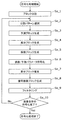
- FIG. 2 is a flowchart illustrating an example of an overall encoding process performed by the encoding device.
- FIG. 3 is a diagram illustrating an example of the block division.
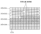
- FIG. 4A is a diagram illustrating an example of the configuration of a slice.
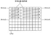
- FIG. 4B is a diagram illustrating an example of the configuration of a tile.
- FIG. 5A is a table showing conversion basis functions corresponding to each conversion type.
- FIG. 5B is a diagram showing an SVT (Spatially Varying Transform).
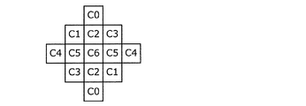
- FIG. 6A is a diagram illustrating an example of the shape of a filter used in an ALF (adaptive loop filter).
- FIG. 1 is a block diagram showing a functional configuration of the encoding device according to the embodiment.
- FIG. 2 is a flowchart illustrating an example of an overall encoding process performed by the encoding device.
- FIG. 3 is
- FIG. 6B is a diagram illustrating another example of the shape of the filter used in the ALF.
- FIG. 6C is a diagram illustrating another example of the shape of the filter used in the ALF.
- FIG. 7 is a block diagram illustrating an example of a detailed configuration of a loop filter unit that functions as a DBF.
- FIG. 8 is a diagram illustrating an example of a deblocking filter having filter characteristics symmetric with respect to a block boundary.
- FIG. 9 is a diagram for explaining a block boundary where deblocking filter processing is performed.
- FIG. 10 is a diagram illustrating an example of the Bs value.
- FIG. 11 is a diagram illustrating an example of processing performed by the prediction processing unit of the encoding device.
- FIG. 12 is a diagram illustrating another example of the processing performed by the prediction processing unit of the encoding device.
- FIG. 13 is a diagram illustrating another example of the processing performed by the prediction processing unit of the encoding device.
- FIG. 14 is a diagram illustrating an example of 67 intra prediction modes in intra prediction.
- FIG. 15 is a flowchart illustrating the flow of the basic process of inter prediction.
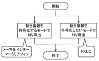
- FIG. 16 is a flowchart illustrating an example of motion vector derivation.
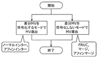
- FIG. 17 is a flowchart illustrating another example of deriving a motion vector.
- FIG. 18 is a flowchart illustrating another example of deriving a motion vector.
- FIG. 19 is a flowchart illustrating an example of inter prediction in the normal inter mode.
- FIG. 20 is a flowchart illustrating an example of inter prediction in the merge mode.
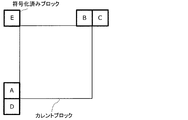
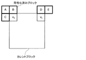
- FIG. 21 is a diagram illustrating an example of a motion vector derivation process in the merge mode.
- FIG. 22 is a flowchart illustrating an example of FRUC (frame ⁇ rate ⁇ up ⁇ conversion).
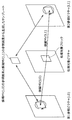
- FIG. 23 is a diagram for describing an example of pattern matching (bilateral matching) between two blocks along a motion trajectory.
- FIG. 24 is a diagram illustrating an example of pattern matching (template matching) between a template in the current picture and a block in the reference picture.
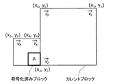
- FIG. 25A is a diagram illustrating an example of deriving a motion vector in sub-block units based on motion vectors of a plurality of adjacent blocks.
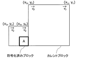
- FIG. 25B is a diagram for describing an example of deriving a motion vector in sub-block units in the affine mode having three control points.
- FIG. 26A is a conceptual diagram for explaining the affine merge mode.
- FIG. 26B is a conceptual diagram illustrating an affine merge mode having two control points.
- FIG. 26C is a conceptual diagram illustrating an affine merge mode having three control points.
- FIG. 27 is a flowchart illustrating an example of the affine merge mode process.
- FIG. 28A is a diagram for describing an affine inter mode having two control points.
- FIG. 28B is a diagram for describing an affine inter mode having three control points.
- FIG. 29 is a flowchart illustrating an example of the affine inter mode processing.
- FIG. 30A is a diagram for describing an affine inter mode in which a current block has three control points and an adjacent block has two control points.
- FIG. 30B is a diagram for describing the affine inter mode in which the current block has two control points and the adjacent block has three control points.
- FIG. 31A is a diagram illustrating a relationship between a merge mode and DMVR (dynamic ⁇ vector ⁇ refreshing).
- FIG. 31B is a conceptual diagram illustrating an example of the DMVR process.
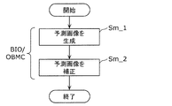
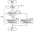
- FIG. 32 is a flowchart illustrating an example of generation of a predicted image.
- FIG. 33 is a flowchart illustrating another example of generation of a predicted image.
- FIG. 34 is a flowchart illustrating still another example of generation of a predicted image.
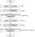
- FIG. 35 is a flowchart for explaining an example of a predicted image correction process by an OBMC (overlapped ⁇ block ⁇ motion ⁇ compensation) process.
- FIG. 36 is a conceptual diagram for describing an example of a predicted image correction process by the OBMC process.
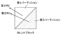
- FIG. 37 is a diagram for explaining generation of a predicted image of two triangles.
- FIG. 38 is a diagram for explaining a model assuming constant velocity linear motion.
- FIG. 39 is a diagram for describing an example of a predicted image generation method using luminance correction processing by LIC (local illumination compensation) processing.
- FIG. 40 is a block diagram illustrating an implementation example of an encoding device.
- FIG. 41 is a block diagram showing a functional configuration of the decoding device according to the embodiment.
- FIG. 42 is a flowchart illustrating an example of the entire decoding process performed by the decoding device.
- FIG. 43 is a diagram illustrating an example of processing performed by the prediction processing unit of the decoding device.
- FIG. 44 is a diagram illustrating another example of processing performed by the prediction processing unit in the decoding device.
- FIG. 45 is a flowchart illustrating an example of inter prediction in the normal inter mode in the decoding device.
- FIG. 46 is a block diagram illustrating an implementation example of a decoding device.
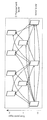
- FIG. 47 is a diagram schematically illustrating a first example of a pipeline configuration of a decoding device according to an embodiment.
- FIG. 48 is a diagram illustrating processing timing in a time sequence of stage processing of each processing target block in the first example of the pipeline configuration of the decoding device according to the embodiment.
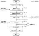
- FIG. 49 is a flowchart illustrating a flow of the inter prediction process in the first example of the pipeline configuration of the decoding device in the embodiment.
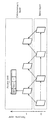
- FIG. 50 is a diagram illustrating an outline of a second example of the pipeline configuration of the decoding device in the embodiment.
- FIG. 51 is a diagram illustrating processing timing in a time sequence of stage processing of each processing target block in the second example of the pipeline configuration of the decoding device according to the embodiment.
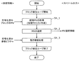
- FIG. 52 is a flowchart illustrating the flow of the inter prediction process in the second example of the pipeline configuration of the decoding device in the embodiment.
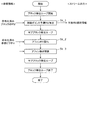
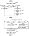
- FIG. 53 is a flowchart illustrating the flow of the inter prediction process in the third example of the pipeline configuration of the decoding device in the embodiment.
- FIG. 54 is a diagram illustrating specific processing of the BIO processing when the predicted image corrected by the LIC processing in the third example of the pipeline configuration of the decoding device in the embodiment is further corrected by the BIO processing. .
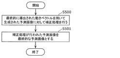
- FIG. 55 is a flowchart illustrating an operation example of the encoding device in the embodiment.
- FIG. 56 is a flowchart illustrating an operation example of the decoding device in the embodiment.
- FIG. 57 is an overall configuration diagram of a content supply system that realizes a content distribution service.
- FIG. 58 is a diagram illustrating an example of an encoding structure during scalable encoding.
- FIG. 59 is a diagram illustrating an example of an encoding structure during scalable encoding.
- FIG. 60 is a diagram illustrating an example of a display screen of a web page.
- FIG. 61 is a diagram illustrating an example of a display screen of a web page.
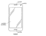
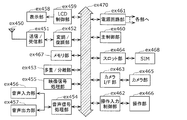
- FIG. 62 is a diagram illustrating an example of a smartphone.
- FIG. 63 is a block diagram illustrating a configuration example of a smartphone.
- an encoding device or the like may detect a motion amount of a subject and perform a process called motion compensation for creating an effective prediction screen using the result.
- the motion compensation (MC: Motion Compensation) process includes a BIO mode for deriving a motion vector based on a model assuming constant-velocity linear motion.
- the motion compensation processing is performed by weighting and adding a prediction signal based on motion information obtained by motion search in a reference picture and a prediction signal based on motion information of an adjacent block in the current picture.
- the motion compensation processing includes an LIC mode for correcting luminance when generating a predicted image.
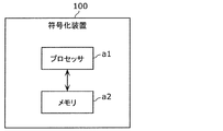
- an encoding device is an encoding device that encodes a moving image using inter prediction processing, including a circuit, and a memory connected to the circuit,
- the circuit when performing a correction process which is an LIC process on a predicted image at the time of the inter prediction process, the circuit generates a motion vector using a motion vector finally derived in a stage before performing the correction process.
- the correction processing is performed on the predicted image, and after the correction processing, the correction processing is performed without applying another correction processing to the prediction image on which the correction processing is performed.
- the predicted image is determined as the final predicted image.
- the encoding apparatus can significantly reduce the feedback performed for deriving the LIC parameter of the reconstructed image of the block adjacent to the processing target block. That is, the encoding apparatus can reduce the processing time of the pipeline control including the LIC processing, and can reduce the waiting time of each processing included in the pipeline control. Therefore, even when the processing performance is low, the possibility that the encoding device completes the processing of all the blocks in the picture within the processing time allocated to one picture increases.
- the finally derived motion vector is DMVR (Dynamic Motion Vector Vector Refreshing). ) A motion vector corrected by the processing.
- the encoding device can use the motion vector with the minimum cost calculated by the DMVR process in the LIC process. Therefore, the encoding device can improve encoding accuracy as compared with the related art.
- the circuit refers to a correction parameter used in the LIC processing in the pipeline processing by referring to a reconstructed image of a processed block around the processing target block. And a process of performing a correction process on the predicted image using the correction parameters are performed in the same processing stage as a process of adding the predicted image and the residual image to generate a reconstructed image.
- the encoding device can perform the LIC parameter derivation process near the end of the inter prediction process. Therefore, the encoding device can reduce the processing time of pipeline control including LIC processing. Therefore, even when the encoding device has low processing performance, it is highly likely that the processing of all blocks included in the picture is completed within the processing time allocated to one picture.
- a decoding device that decodes a moving image using inter prediction processing, and includes a circuit, and a memory connected to the circuit, and the circuit includes:
- the correction processing when performing the correction processing which is the LIC processing on the prediction image at the time of the inter prediction processing, the correction processing is performed using the finally derived motion vector in a stage before performing the correction processing.
- the correction processing is performed on the predicted image, and after the correction processing, the predicted image on which the correction processing has been performed without applying another correction processing to the predicted image on which the correction processing has been performed. Is determined as the final predicted image.
- the decoding apparatus can greatly reduce the feedback performed for deriving the LIC parameter of the reconstructed image of the block adjacent to the processing target block. That is, the decoding apparatus can reduce the processing time of the pipeline control including the LIC processing, and can reduce the waiting time of each processing included in the pipeline control. Therefore, even when the decoding performance is low, the possibility that the processing of all blocks in the picture is completed within the processing time allocated to one picture increases.
- the finally derived motion vector is a motion vector corrected by the DMVR process when the inter prediction mode in the inter prediction process is the merge mode. Vector.
- the decoding device can use the motion vector having the minimum cost calculated by the DMVR process in the LIC process. Therefore, the decoding device can improve decoding accuracy as compared with the related art.
- the circuit in the pipeline processing, refers to a reconstructed image of a processed block around a processing target block and adjusts a correction parameter used in the LIC processing.
- the process of deriving and the process of correcting the predicted image using the correction parameters are performed in the same processing stage as the process of adding the predicted image and the residual image to generate a reconstructed image.
- the decoding device can perform the LIC parameter derivation process near the end of the inter prediction process. Therefore, the decoding device can reduce the processing time of the pipeline control including the LIC processing. Therefore, even when the decoding performance is low, the possibility that the processing of all the blocks included in the picture is completed within the processing time allocated to one picture increases.
- an encoding method is an encoding method that encodes a moving image using inter prediction processing, and in the case of the inter prediction processing, is an LIC processing for a prediction image.
- the correction process is performed on the predicted image generated using the finally derived motion vector, and after the correction process, Without applying another correction process to the predicted image subjected to the correction process, the predicted image subjected to the correction process is determined as a final predicted image.
- the encoding method can achieve the same effect as the above-described encoding device.
- a decoding method is a decoding method for decoding a moving image using inter prediction processing, and performs a correction process, which is LIC processing on a predicted image, at the time of the inter prediction process.
- the correction processing is performed on the predicted image generated using the finally derived motion vector at a stage before performing the correction processing, and the correction processing is performed after the correction processing. Without applying other correction processing to the predicted image on which the correction processing has been performed, the predicted image on which the correction processing has been performed is determined as a final predicted image.
- the decoding method can provide the same effect as the above-described decoding device.
- the encoding device includes a dividing unit, an intra prediction unit, an inter prediction unit, a loop filter unit, a conversion unit, a quantization unit, and an entropy encoding unit. May be provided.
- the division unit may divide a picture into a plurality of blocks.
- the intra prediction unit may perform intra prediction on a block included in the plurality of blocks.
- the inter prediction unit may perform inter prediction on the block.
- the conversion unit may generate a conversion coefficient by converting a prediction error between a prediction image obtained by the intra prediction or the inter prediction and an original image.
- the quantizer may quantize the transform coefficient to generate a quantized coefficient.
- the entropy encoding unit may encode the quantized coefficients to generate an encoded bit stream.
- the loop filter unit may apply a filter to a reconstructed image of the block.
- the encoding device may be an encoding device that encodes a moving image including a plurality of pictures.
- the inter prediction unit when performing the correction process as the LIC process on the predicted image at the time of the inter prediction process, the inter prediction unit generates the inter prediction unit by using the motion vector finally derived in a stage before performing the correction process.
- the correction processing is performed on the predicted image, and after the correction processing, the correction processing is performed without applying another correction processing to the prediction image on which the correction processing is performed.
- the predicted image may be determined as a final predicted image.
- the decoding device may include an entropy decoding unit, an inverse quantization unit, an inverse transform unit, an intra prediction unit, an inter prediction unit, and a loop filter unit. .
- the entropy decoding unit may decode a quantized coefficient of a block in a picture from an encoded bit stream.
- the inverse quantization unit may inversely quantize the quantized coefficient to obtain a transform coefficient.
- the inverse transform unit may inversely transform the transform coefficient to obtain a prediction error.
- the intra prediction unit may perform intra prediction on the block.
- the inter prediction unit may perform inter prediction on the block.
- the filter unit may apply a filter to a reconstructed image generated using the prediction error obtained by the intra prediction or the inter prediction and the prediction error.
- the decoding device may be a decoding device that decodes a moving image including a plurality of pictures.
- the inter prediction unit uses the finally derived motion vector in a stage before performing the correction process, when performing the correction process as the LIC process on the predicted image at the time of the inter prediction process.
- the correction processing was performed on the generated prediction image, and after the correction processing, the correction processing was performed without applying another correction processing to the prediction image on which the correction processing was performed.
- the predicted image may be determined as a final predicted image.
- a non-transitory recording medium such as a system, an apparatus, a method, an integrated circuit, a computer program, or a computer-readable CD-ROM.
- An apparatus, a method, an integrated circuit, a computer program, and a recording medium may be implemented in a non-transitory recording medium such as a system, an apparatus, a method, an integrated circuit, a computer program, or a computer-readable CD-ROM.
- Embodiments are examples of an encoding device and a decoding device to which the processing and / or configuration described in each aspect of the present disclosure can be applied.
- the processing and / or configuration can be implemented in an encoding device and a decoding device different from those in the embodiment.
- any of the following may be performed.
- Some of the components constituting the encoding device or the decoding device according to the embodiment may be combined with components described in any of the aspects of the present disclosure. May be combined with a component having a part of the function described in any of the aspects of the present disclosure, or a component that performs a part of a process performed by the component described in each of the aspects of the present disclosure May be combined.
- a component having a part of the function of the encoding device or the decoding device according to the embodiment, or a component performing a part of the processing of the encoding device or the decoding device according to the embodiment A component described in any of the aspects, a component having a part of the function described in any of the aspects of the present disclosure, or a part of the processing described in any of the aspects of the present disclosure It may be combined with or replaced by a component to be implemented.
- any one of a plurality of processes included in the method may be a process described in any of the aspects of the present disclosure, or may be a similar process. Any of the processes may be replaced or combined.
- the manner of implementing the processing and / or configuration described in each aspect of the present disclosure is not limited to the encoding device or the decoding device according to the embodiment.
- the processing and / or the configuration may be performed in an apparatus used for a purpose different from the moving image encoding or the moving image decoding disclosed in the embodiment.
- FIG. 1 is a block diagram showing a functional configuration of an encoding device 100 according to the present embodiment.
- the encoding device 100 is a moving image encoding device that encodes a moving image in block units.
- an encoding apparatus 100 is an apparatus that encodes an image in units of blocks, and includes a division unit 102, a subtraction unit 104, a conversion unit 106, a quantization unit 108, and entropy encoding.
- Unit 110 inverse quantization unit 112, inverse transform unit 114, addition unit 116, block memory 118, loop filter unit 120, frame memory 122, intra prediction unit 124, inter prediction unit 126, And a prediction control unit 128.
- the encoding device 100 is realized by, for example, a general-purpose processor and a memory.
- the processor when the software program stored in the memory is executed by the processor, the processor includes the dividing unit 102, the subtracting unit 104, the transforming unit 106, the quantizing unit 108, the entropy encoding unit 110, and the inverse quantizing unit 112. , The inverse transform section 114, the adder section 116, the loop filter section 120, the intra prediction section 124, the inter prediction section 126, and the prediction control section 128.
- the encoding apparatus 100 includes a dividing unit 102, a subtracting unit 104, a transforming unit 106, a quantizing unit 108, an entropy encoding unit 110, an inverse quantizing unit 112, an inverse transforming unit 114, an adding unit 116, and a loop filter unit 120. , The intra prediction unit 124, the inter prediction unit 126, and the prediction control unit 128.
- FIG. 2 is a flowchart illustrating an example of an overall encoding process performed by the encoding device 100.
- the dividing unit 102 of the encoding device 100 divides each picture included in an input image that is a moving image into a plurality of fixed-size blocks (128 ⁇ 128 pixels) (Step Sa_1). Then, the division unit 102 selects a division pattern (also referred to as a block shape) for the fixed-size block (Step Sa_2). That is, the dividing unit 102 further divides the fixed-size block into a plurality of blocks forming the selected division pattern. Then, for each of the plurality of blocks, the encoding device 100 performs the processing of steps Sa_3 to Sa_9 on the block (that is, the encoding target block).
- a division pattern also referred to as a block shape
- the prediction processing unit including all or a part of the intra prediction unit 124, the inter prediction unit 126, and the prediction control unit 128 generates a prediction signal (also referred to as a prediction block) of the current block (also referred to as a current block). (Step Sa_3).
- Step Sa_4 the subtraction unit 104 generates a difference between the current block and the prediction block as a prediction residual (also referred to as a difference block) (Step Sa_4).
- the conversion unit 106 and the quantization unit 108 generate a plurality of quantized coefficients by performing conversion and quantization on the difference block (step Sa_5).
- a block including a plurality of quantized coefficients is also referred to as a coefficient block.
- the entropy coding unit 110 generates a coded signal by performing coding (specifically, entropy coding) on the coefficient block and a prediction parameter related to generation of a prediction signal (step S ⁇ b> 1). Sa_6).
- the encoded signal is also referred to as an encoded bit stream, a compressed bit stream, or a stream.
- the inverse quantization unit 112 and the inverse transformation unit 114 restore a plurality of prediction residuals (that is, difference blocks) by performing inverse quantization and inverse transformation on the coefficient block (step Sa_7).
- the adding unit 116 reconstructs the current block into a reconstructed image (also referred to as a reconstructed block or a decoded image block) by adding a prediction block to the restored difference block (step Sa_8). As a result, a reconstructed image is generated.
- a reconstructed image also referred to as a reconstructed block or a decoded image block
- the loop filter unit 120 performs filtering on the reconstructed image as needed (step Sa_9).
- step Sa_10 determines whether or not the coding of the entire picture has been completed (step Sa_10), and when it is determined that the coding has not been completed (No in step Sa_10), the processing from step Sa_2 is repeatedly executed. I do.
- the encoding device 100 selects one division pattern for a fixed-size block and encodes each block according to the division pattern. Each block may be coded. In this case, the encoding device 100 evaluates the cost for each of the plurality of division patterns, and for example, converts the encoded signal obtained by encoding according to the division pattern with the lowest cost into the finally output code. May be selected as the conversion signal.
- steps Sa_1 to Sa_10 may be sequentially performed by the encoding device 100, some of the processing may be performed in parallel, and the order may be changed. You may.
- the division unit 102 divides each picture included in the input moving image into a plurality of blocks, and outputs each block to the subtraction unit 104.
- the division unit 102 first divides a picture into blocks of a fixed size (for example, 128 ⁇ 128). This fixed size block may be referred to as a coding tree unit (CTU).
- the dividing unit 102 divides each of the fixed-size blocks into variable-size (for example, 64 ⁇ 64 or less) blocks based on, for example, recursive quadtree and / or binary tree block division. I do. That is, the division unit 102 selects a division pattern.
- This variable size block may be called a coding unit (CU), a prediction unit (PU), or a transform unit (TU).
- CUs, PUs, and TUs do not need to be distinguished, and some or all blocks in a picture may be processing units of the CUs, PUs, and TUs.
- FIG. 3 is a diagram illustrating an example of block division according to the present embodiment.
- a solid line represents a block boundary obtained by dividing a quadtree block
- a broken line represents a block boundary obtained by dividing a binary tree block.
- the block 10 is a square block of 128 ⁇ 128 pixels (128 ⁇ 128 block).
- the 128 ⁇ 128 block 10 is first divided into four square 64 ⁇ 64 blocks (quad tree block division).
- the upper left 64 ⁇ 64 block is further vertically divided into two rectangular 32 ⁇ 64 blocks, and the left 32 ⁇ 64 block is further vertically divided into two rectangular 16 ⁇ 64 blocks (binary tree block division). As a result, the upper left 64 ⁇ 64 block is divided into two 16 ⁇ 64 blocks 11 and 12 and a 32 ⁇ 64 block 13.
- the upper right 64 ⁇ 64 block is horizontally divided into two rectangular 64 ⁇ 32 blocks 14 and 15 (binary tree block division).
- the lower left 64 ⁇ 64 block is divided into four square 32 ⁇ 32 blocks (quad tree block division).
- the upper left block and the lower right block of the four 32 ⁇ 32 blocks are further divided.
- the upper left 32 ⁇ 32 block is vertically divided into two rectangular 16 ⁇ 32 blocks, and the right 16 ⁇ 32 block is further horizontally divided into two 16 ⁇ 16 blocks (binary tree block division).
- the lower right 32 ⁇ 32 block is horizontally divided into two 32 ⁇ 16 blocks (binary tree block division).
- the lower left 64x64 block is divided into a 16x32 block 16, two 16x16 blocks 17,18, two 32x32 blocks 19,20, and two 32x16 blocks 21,22.
- the block 10 is divided into thirteen variable-size blocks 11 to 23 based on recursive quadtree and binary tree block division.
- Such division may be referred to as QTBT (quad-tree ⁇ plus ⁇ binary ⁇ tree) division.
- one block is divided into four or two blocks (quadtree or binary tree block division), but the division is not limited to these.
- one block may be divided into three blocks (triple tree block division).
- a division including such a ternary tree block division may be referred to as MBT (multimtype tree) division.
- Picture composition slice / tile In order to decode pictures in parallel, the pictures may be configured in slice units or tile units. A picture composed of slice units or tile units may be configured by the division unit 102.
- Slice is a basic unit of coding that constitutes a picture.
- a picture is composed of, for example, one or more slices.
- a slice is composed of one or more continuous CTUs (Coding Tree Units).
- FIG. 4A is a diagram showing an example of the configuration of a slice.
- a picture includes 11 ⁇ 8 CTUs and is divided into four slices (slices 1-4).
- Slice 1 is composed of 16 CTUs
- slice 2 is composed of 21 CTUs
- slice 3 is composed of 29 CTUs
- slice 4 is composed of 22 CTUs.
- each CTU in the picture belongs to one of the slices.
- the shape of the slice is a shape obtained by dividing the picture in the horizontal direction.
- the boundary of the slice does not need to be the edge of the screen, and may be any of the boundaries of the CTU in the screen.
- the processing order (encoding order or decoding order) of the CTU in the slice is, for example, a raster scan order.
- Each slice includes header information and encoded data.
- the header information may describe characteristics of the slice, such as the CTU address at the head of the slice and the slice type.
- a tile is a unit of a rectangular area constituting a picture.
- a number called TileId may be assigned to each tile in raster scan order.
- FIG. 4B is a diagram showing an example of the configuration of a tile.
- a picture includes 11 ⁇ 8 CTUs and is divided into four rectangular area tiles (tiles 1-4).
- the processing order of the CTU is changed as compared with the case where the tile is not used. If no tiles are used, the CTUs in the picture are processed in raster scan order. If tiles are used, at least one CTU in each of the plurality of tiles is processed in raster scan order. For example, as shown in FIG.
- the processing order of a plurality of CTUs included in tile 1 is from the left end of the first column of tile 1 to the right end of the first column of tile 1, and then the left end of the second column of tile 1 To the right end of the second column of the tile 1.
- one tile may include one or more slices, and one slice may include one or more tiles.
- the subtraction unit 104 subtracts a prediction signal (a prediction sample input from the prediction control unit 128 shown below) from an original signal (original sample) in block units input from the division unit 102 and divided by the division unit 102. . That is, the subtraction unit 104 calculates a prediction error (also referred to as a residual) of the current block (hereinafter, referred to as a current block). Then, the subtraction unit 104 outputs the calculated prediction error (residual error) to the conversion unit 106.
- a prediction signal a prediction sample input from the prediction control unit 128 shown below
- the original signal is an input signal of the encoding apparatus 100, and is a signal (for example, a luminance (luma) signal and two color difference (chroma) signals) representing an image of each picture constituting a moving image.
- a signal representing an image may be referred to as a sample.
- Transform section 106 transforms the prediction error in the spatial domain into transform coefficients in the frequency domain, and outputs the transform coefficients to quantization section 108. Specifically, the transform unit 106 performs, for example, a discrete cosine transform (DCT) or a discrete sine transform (DST) on a prediction error in a spatial domain.
- DCT discrete cosine transform
- DST discrete sine transform
- the conversion unit 106 adaptively selects a conversion type from a plurality of conversion types, and converts the prediction error into a conversion coefficient using a conversion basis function (transform basis function) corresponding to the selected conversion type. May be. Such a conversion is sometimes called EMT (explicit multiple core transform) or AMT (adaptive multiple multiple transform).
- EMT express multiple core transform
- AMT adaptive multiple multiple transform
- the plurality of conversion types include, for example, DCT-II, DCT-V, DCT-VIII, DST-I and DST-VII.
- FIG. 5A is a table showing conversion basis functions corresponding to each conversion type.
- N indicates the number of input pixels. Selection of a conversion type from among the plurality of conversion types may depend on, for example, the type of prediction (intra prediction and inter prediction) or may depend on the intra prediction mode.
- the information indicating whether to apply such EMT or AMT (for example, referred to as an EMT flag or an AMT flag) and the information indicating the selected conversion type are usually signaled at the CU level.
- the signalization of these pieces of information need not be limited to the CU level, but may be another level (for example, a bit sequence level, a picture level, a slice level, a tile level, or a CTU level).
- the conversion unit 106 may re-convert the conversion coefficient (conversion result). Such re-transformation may be referred to as AST (adaptive @ secondary @ transform) or NSST (non-separable @ secondary @ transform). For example, the transform unit 106 performs re-conversion for each sub-block (for example, a 4 ⁇ 4 sub-block) included in a block of a transform coefficient corresponding to an intra prediction error.
- the information indicating whether to apply the NSST and the information on the transformation matrix used for the NSST are usually signaled at the CU level. The signalization of these pieces of information need not be limited to the CU level, but may be another level (for example, a sequence level, a picture level, a slice level, a tile level, or a CTU level).
- Separable conversion and Non-Separable conversion may be applied to the conversion unit 106.
- Separable conversion is a method of performing conversion a plurality of times by separating each direction by the number of input dimensions.
- Non-separable conversion is a method of converting two or more dimensions when the input is multidimensional. This is a method in which conversion is performed collectively assuming that the data is one-dimensional.
- an input is a 4 ⁇ 4 block, it is regarded as one array having 16 elements, and a 16 ⁇ 16 conversion matrix is applied to the array. , Which performs the conversion process.
- a conversion in which a 4 ⁇ 4 input block is regarded as one array having 16 elements, and a Givens rotation is performed on the array a plurality of times (Hypercube). Gives @ Transform) may be performed.
- the type of base to be converted to the frequency domain can be switched according to the area in the CU.
- SVT Spaally Varying Transform
- the CU is divided into two equal parts in the horizontal or vertical direction, and only one of the areas is converted into the frequency area.
- the type of the transformation base can be set for each area, and for example, DST7 and DCT8 are used. In this example, only one of the two areas in the CU is converted and the other is not converted, but both areas may be converted.
- the dividing method can be made more flexible, such as not only dividing into two, but also dividing into four, or information indicating the division is separately encoded and signaled similarly to the CU division.
- the SVT may be referred to as SBT (Sub-block @ Transform).
- the quantization unit 108 quantizes the transform coefficient output from the transform unit 106. Specifically, the quantization unit 108 scans the transform coefficients of the current block in a predetermined scanning order, and quantizes the transform coefficients based on the quantization parameter (QP) corresponding to the scanned transform coefficients. Then, the quantization unit 108 outputs the quantized transform coefficients of the current block (hereinafter, referred to as quantization coefficients) to the entropy encoding unit 110 and the inverse quantization unit 112.
- QP quantization parameter
- the predetermined scanning order is an order for quantization / inverse quantization of transform coefficients.
- the predetermined scanning order is defined as an ascending order of frequency (low-frequency to high-frequency) or a descending order (high-frequency to low-frequency).
- the quantization parameter is a parameter that defines a quantization step (quantization width). For example, as the value of the quantization parameter increases, the quantization step also increases. That is, as the value of the quantization parameter increases, the quantization error increases.
- a quantization matrix is used for quantization.
- quantization matrices may be used in correspondence with frequency transform sizes such as 4x4 and 8x8, prediction modes such as intra prediction and inter prediction, and pixel components such as luminance and color difference.
- quantization refers to digitizing a value sampled at a predetermined interval in association with a predetermined level, and in this technical field, expressions such as rounding, rounding, and scaling are used. There is also.
- a method of using a quantization matrix there are a method of using a quantization matrix directly set on the encoding device side and a method of using a default quantization matrix (default matrix).
- default matrix default matrix
- the quantization matrix it is possible to set the quantization matrix according to the characteristics of the image.
- the coding amount is increased by coding the quantization matrix.
- the ⁇ ⁇ ⁇ ⁇ ⁇ ⁇ ⁇ ⁇ quantization matrix may be specified by, for example, SPS (Sequence Parameter Set: Sequence Parameter Set) or PPS (Picture Parameter Set: Picture Parameter Set).
- SPS Sequence Parameter Set: Sequence Parameter Set
- PPS Picture Parameter Set
- the SPS includes parameters used for sequences
- the PPS includes parameters used for pictures.
- SPS and PPS may be simply referred to as a parameter set.
- the entropy coding unit 110 generates a coded signal (coded bit stream) based on the quantized coefficients input from the quantization unit 108. Specifically, for example, the entropy encoding unit 110 binarizes the quantized coefficients, arithmetically encodes the binary signal, and outputs a compressed bit stream or sequence.
- the inverse quantization unit 112 inversely quantizes the quantization coefficient input from the quantization unit 108. Specifically, the inverse quantization unit 112 inversely quantizes the quantization coefficient of the current block in a predetermined scanning order. Then, the inverse quantization unit 112 outputs the inversely quantized transform coefficient of the current block to the inverse transformation unit 114.
- the inverse transform unit 114 restores a prediction error (residual error) by inversely transforming the transform coefficient input from the inverse quantization unit 112. Specifically, the inverse transform unit 114 restores the prediction error of the current block by performing an inverse transform corresponding to the transform by the transform unit 106 on the transform coefficient. Then, the inverse transform unit 114 outputs the restored prediction error to the adding unit 116.
- the restored prediction error usually does not match the prediction error calculated by the subtraction unit 104 because information is lost due to quantization. That is, the restored prediction error usually includes a quantization error.
- the addition unit 116 reconstructs the current block by adding the prediction error input from the inverse transform unit 114 and the prediction sample input from the prediction control unit 128. Then, the adding unit 116 outputs the reconstructed block to the block memory 118 and the loop filter unit 120.
- the reconstructed block is sometimes called a local decoding block.
- the block memory 118 is, for example, a storage unit for storing a block that is referred to in intra prediction and is in a current picture to be coded (called a current picture). Specifically, the block memory 118 stores the reconstructed block output from the adding unit 116.
- the frame memory 122 is, for example, a storage unit for storing reference pictures used for inter prediction, and may be called a frame buffer. Specifically, the frame memory 122 stores the reconstructed blocks filtered by the loop filter unit 120.
- the loop filter unit 120 applies a loop filter to the block reconstructed by the adding unit 116, and outputs the reconstructed block that has been filtered to the frame memory 122.
- the loop filter is a filter (in-loop filter) used in the encoding loop, and includes, for example, a deblocking filter (DF or DBF), a sample adaptive offset (SAO), an adaptive loop filter (ALF), and the like.
- a least squares error filter for removing coding distortion is applied. For example, for every 2 ⁇ 2 sub-block in the current block, a plurality of sub-blocks are determined based on the direction and activity of a local gradient. One filter selected from the filters is applied.
- sub-blocks for example, 2 ⁇ 2 sub-blocks
- a plurality of classes for example, 15 or 25 classes.
- the classification of the sub-blocks is performed based on the direction and the activity of the gradient.
- the sub-blocks are classified into a plurality of classes based on the classification value C.
- the gradient direction value D is derived, for example, by comparing gradients in a plurality of directions (for example, horizontal, vertical and two diagonal directions).
- the gradient activation value A is derived, for example, by adding gradients in a plurality of directions and quantizing the addition result.
- a filter for a sub-block is determined from a plurality of filters based on the result of such classification.
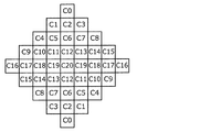
- FIG. 6A to 6C are views showing a plurality of examples of the shape of the filter used in the ALF.
- 6A shows a 5 ⁇ 5 diamond-shaped filter
- FIG. 6B shows a 7 ⁇ 7 diamond-shaped filter
- FIG. 6C shows a 9 ⁇ 9 diamond-shaped filter.
- the information indicating the shape of the filter is usually signaled at the picture level.
- the signalization of the information indicating the shape of the filter need not be limited to the picture level, but may be another level (for example, a sequence level, a slice level, a tile level, a CTU level, or a CU level).
- $ ON / OFF of ALF may be determined, for example, at a picture level or a CU level. For example, whether to apply ALF at the CU level may be determined for luminance, and whether to apply ALF at the picture level may be determined for color difference.
- the information indicating ALF on / off is usually signaled at a picture level or a CU level.
- the signalization of the information indicating ON / OFF of the ALF does not need to be limited to the picture level or the CU level, and may be at another level (for example, a sequence level, a slice level, a tile level, or a CTU level). Good.
- the set of coefficients for a plurality of selectable filters is usually signaled at the picture level.
- the signalization of the coefficient set need not be limited to the picture level, but may be another level (for example, a sequence level, a slice level, a tile level, a CTU level, a CU level, or a sub-block level).
- the loop filter unit 120 performs a filtering process on a block boundary of a reconstructed image to reduce distortion generated at the block boundary.
- FIG. 7 is a block diagram showing an example of a detailed configuration of the loop filter unit 120 functioning as a deblocking filter.
- the loop filter unit 120 includes a boundary determination unit 1201, a filter determination unit 1203, a filter processing unit 1205, a processing determination unit 1208, a filter characteristic determination unit 1207, and switches 1202, 1204, and 1206.
- the boundary determination unit 1201 determines whether or not a pixel to be subjected to deblocking filtering (that is, a target pixel) exists near a block boundary. Then, boundary determination section 1201 outputs the determination result to switch 1202 and processing determination section 1208.
- the switch 1202 When the boundary determination unit 1201 determines that the target pixel exists near the block boundary, the switch 1202 outputs the image before the filter processing to the switch 1204. Conversely, when the boundary determination unit 1201 determines that the target pixel does not exist near the block boundary, the switch 1202 outputs the image before the filter processing to the switch 1206.
- the filter determination unit 1203 determines whether to perform the deblocking filter processing on the target pixel based on the pixel values of at least one peripheral pixel around the target pixel. Then, filter determination section 1203 outputs the determination result to switch 1204 and processing determination section 1208.
- the switch 1204 If the filter determination unit 1203 determines that the deblocking filter processing is to be performed on the target pixel, the switch 1204 outputs the image before the filter processing obtained via the switch 1202 to the filter processing unit 1205. Conversely, when the filter determination unit 1203 determines that the deblocking filter processing is not performed on the target pixel, the switch 1204 outputs the image before the filter processing acquired via the switch 1202 to the switch 1206.
- the filter processing unit 1205 When acquiring the image before the filter processing via the switches 1202 and 1204, the filter processing unit 1205 performs the deblocking filter processing having the filter characteristics determined by the filter characteristic determination unit 1207 on the target pixel. Execute. Then, the filter processing unit 1205 outputs the pixel after the filter processing to the switch 1206.
- the switch 1206 selectively outputs a pixel that has not been deblocking-filtered and a pixel that has been deblocking-filtered by the filter processing unit 1205 under the control of the processing determination unit 1208.
- the processing determination unit 1208 controls the switch 1206 based on the determination results of the boundary determination unit 1201 and the filter determination unit 1203. That is, when the processing determination unit 1208 determines that the target pixel exists near the block boundary by the boundary determination unit 1201 and determines that the filter determination unit 1203 performs the deblocking filter processing on the target pixel. , The pixel subjected to the deblocking filter processing is output from the switch 1206. In cases other than those described above, the processing determining unit 1208 causes the switch 1206 to output a pixel that has not been subjected to the deblocking filter processing. By repeatedly outputting such pixels, the image after the filter processing is output from the switch 1206.
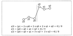
- FIG. 8 is a diagram showing an example of a deblocking filter having filter characteristics symmetric with respect to a block boundary.
- one of two deblocking filters having different characteristics that is, a strong filter and a weak filter is selected using a pixel value and a quantization parameter.
- the strong filter as shown in FIG. 8, when there are pixels p0 to p2 and pixels q0 to q2 across a block boundary, the pixel values of the pixels q0 to q2 are calculated by the following equations. By doing so, the pixel values are changed to pixel values q'0 to q'2.
- p0 to p2 and q0 to q2 are the pixel values of pixels p0 to p2 and pixels q0 to q2, respectively.
- q3 is a pixel value of the pixel q3 adjacent to the pixel q2 on the opposite side to the block boundary.
- a coefficient by which the pixel value of each pixel used in the deblocking filter processing is multiplied is a filter coefficient.
- clip processing may be performed so that the pixel value after calculation does not change beyond the threshold value.
- the pixel value after the calculation according to the above equation is clipped to “pixel value before calculation ⁇ 2 ⁇ threshold” using the threshold value determined from the quantization parameter. Thereby, excessive smoothing can be prevented.
- FIG. 9 is a diagram for explaining a block boundary where deblocking filter processing is performed.
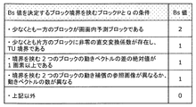
- FIG. 10 is a diagram illustrating an example of the Bs value.
- the block boundary where the deblocking filter processing is performed is, for example, a boundary of a PU (Prediction @ Unit) or a TU (Transform @ Unit) of an 8 ⁇ 8 pixel block as shown in FIG.
- the deblocking filter processing is performed in units of four rows or four columns.
- a Bs (Boundary Strength) value is determined for the blocks P and Q shown in FIG. 9 as shown in FIG.
- the deblocking filter processing on the color difference signal is performed when the Bs value is 2.
- the deblocking filter processing on the luminance signal is performed when the Bs value is 1 or more and a predetermined condition is satisfied. Note that the determination condition of the Bs value is not limited to the one shown in FIG. 10 and may be determined based on another parameter.
- FIG. 11 is a diagram illustrating an example of processing performed by the prediction processing unit of the encoding device 100.
- the prediction processing unit includes all or some components of the intra prediction unit 124, the inter prediction unit 126, and the prediction control unit 128.
- the prediction processing unit generates a predicted image of the current block (Step Sb_1).
- This prediction image is also called a prediction signal or a prediction block.
- the prediction signal includes, for example, an intra prediction signal or an inter prediction signal.
- the prediction processing unit generates a reconstructed image that has already been obtained by performing generation of a prediction block, generation of a difference block, generation of a coefficient block, restoration of a difference block, and generation of a decoded image block. To generate a predicted image of the current block.
- the reconstructed image may be, for example, an image of a reference picture or an image of a coded block in the current picture which is a picture including the current block.
- the coded block in the current picture is, for example, a block adjacent to the current block.
- FIG. 12 is a diagram illustrating another example of the processing performed by the prediction processing unit of the encoding device 100.
- the prediction processing unit generates a predicted image using the first method (Step Sc_1a), generates a predicted image using the second method (Step Sc_1b), and generates a predicted image using the third method (Step Sc_1c).
- the first scheme, the second scheme, and the third scheme are different schemes for generating a predicted image, and are, for example, inter prediction schemes, intra prediction schemes, and other prediction schemes, respectively. There may be. In these prediction methods, the above-described reconstructed image may be used.
- the prediction processing unit selects one of the plurality of predicted images generated in steps Sc_1a, Sc_1b, and Sc_1c (step Sc_2).
- the selection of the predicted image that is, the selection of a method or a mode for obtaining a final predicted image may be performed based on the calculated cost for each generated predicted image. Alternatively, the selection of the predicted image may be performed based on parameters used for the encoding process.
- the encoding device 100 may signal information for specifying the selected predicted image, scheme, or mode into an encoded signal (also referred to as an encoded bit stream). The information may be, for example, a flag. Thereby, the decoding device can generate a predicted image according to the method or mode selected in encoding device 100 based on the information.
- the prediction processing unit selects one of the predicted images after generating the predicted image in each method.
- the prediction processing unit before generating those predicted images, based on the parameters used in the above-described encoding processing, select a method or mode, and generate a predicted image according to the method or mode Is also good.
- the first method and the second method are intra prediction and inter prediction, respectively, and the prediction processing unit generates a final prediction image for the current block from prediction images generated according to these prediction methods. You may choose.
- FIG. 13 is a diagram illustrating another example of the processing performed by the prediction processing unit of the encoding device 100.
- the prediction processing unit generates a predicted image by intra prediction (step Sd_1a), and generates a predicted image by inter prediction (step Sd_1b).
- a predicted image generated by intra prediction is also called an intra predicted image
- a predicted image generated by inter prediction is also called an inter predicted image.
- the prediction processing unit evaluates each of the intra prediction image and the inter prediction image (Step Sd_2). Cost may be used for this evaluation. That is, the prediction processing unit calculates the respective costs C of the intra prediction image and the inter prediction image.
- D is the encoding distortion of the predicted image, and is represented by, for example, the sum of absolute differences between the pixel value of the current block and the pixel value of the predicted image.
- R is the amount of generated code of the predicted image, and specifically, is the amount of code required for encoding motion information and the like for generating the predicted image.
- ⁇ is, for example, an undetermined Lagrange multiplier.
- the prediction processing unit selects, from the intra-predicted image and the inter-predicted image, the predicted image with the smallest cost C calculated as the final predicted image of the current block (Step Sd_3). That is, a prediction method or mode for generating a prediction image of the current block is selected.
- the intra prediction unit 124 generates a prediction signal (intra prediction signal) by performing intra prediction (also referred to as intra prediction) of the current block with reference to a block in the current picture stored in the block memory 118. Specifically, the intra prediction unit 124 generates an intra prediction signal by performing intra prediction with reference to a sample (for example, a luminance value and a color difference value) of a block adjacent to the current block, and performs prediction control on the intra prediction signal. Output to the unit 128.
- intra prediction signal intra prediction signal
- intra prediction also referred to as intra prediction
- the intra prediction unit 124 performs intra prediction using one of a plurality of intra prediction modes defined in advance.
- the plurality of intra prediction modes usually includes one or more non-directional prediction modes and a plurality of directional prediction modes.
- the one or more non-directional prediction modes are, for example, H.264. It includes a Planar prediction mode and a DC prediction mode defined by the H.265 / HEVC standard.
- the plurality of direction prediction modes are, for example, H.264. Includes a prediction mode in 33 directions defined by the H.265 / HEVC standard. Note that the plurality of directional prediction modes may further include 32 directional prediction modes (total of 65 directional prediction modes) in addition to the 33 directions.
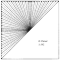
- FIG. 14 is a diagram illustrating a total of 67 intra prediction modes (two non-directional prediction modes and 65 directional prediction modes) in intra prediction. Solid arrows indicate H.E. H.265 / HEVC standard indicates 33 directions, and broken arrows indicate the added 32 directions. (Two non-directional prediction modes are not shown in FIG. 14.)
- a luminance block may be referred to in intra prediction of a chrominance block. That is, the color difference component of the current block may be predicted based on the luminance component of the current block.
- Such intra prediction is sometimes called CCLM (cross-component @ linear @ model) prediction.
- CCLM cross-component @ linear @ model
- Such an intra prediction mode of a chrominance block that refers to a luminance block may be added as one of the intra prediction modes of a chrominance block.
- the intra prediction unit 124 may correct the pixel value after intra prediction based on the gradient of the reference pixel in the horizontal / vertical direction. Intra prediction with such a correction is sometimes called PDPC (position ⁇ dependent ⁇ intra ⁇ prediction ⁇ combination). Information indicating whether or not PDPC is applied (for example, called a PDPC flag) is usually signaled at the CU level. The signalization of this information need not be limited to the CU level, but may be another level (for example, a sequence level, a picture level, a slice level, a tile level, or a CTU level).
- the inter prediction unit 126 performs inter prediction (also referred to as inter-screen prediction) of the current block with reference to a reference picture stored in the frame memory 122 and being different from the current picture, thereby obtaining a prediction signal (inter prediction).
- the inter prediction is performed in units of a current block or a current sub-block (for example, 4 ⁇ 4 block) in the current block.
- the inter prediction unit 126 performs motion estimation on the current block or the current sub-block in the reference picture, and finds a reference block or a sub-block that best matches the current block or the current sub-block.
- the inter prediction unit 126 acquires motion information (for example, a motion vector) that compensates for a motion or change from the reference block or the sub-block to the current block or the sub-block.
- the inter prediction unit 126 performs motion compensation (or motion prediction) based on the motion information, and generates an inter prediction signal of a current block or a sub block.
- the inter prediction unit 126 outputs the generated inter prediction signal to the prediction control unit 128.
- the motion information used for motion compensation may be signaled as an inter prediction signal in various forms.
- a motion vector may be signalized.
- a difference between a motion vector and a predicted motion vector may be signalized.
- FIG. 15 is a flowchart showing a basic flow of inter prediction.
- the inter prediction unit 126 first generates a predicted image (Steps Se_1 to Se_3). Next, the subtraction unit 104 generates a difference between the current block and the predicted image as a prediction residual (Step Se_4).
- the inter prediction unit 126 determines the motion vector (MV) of the current block (Steps Se_1 and Se_2) and performs motion compensation (Step Se_3) to generate the predicted image. I do.
- the inter prediction unit 126 determines the MV by selecting a candidate motion vector (candidate MV) (Step Se_1) and deriving the MV (Step Se_2). The selection of the candidate MV is performed, for example, by selecting at least one candidate MV from the candidate MV list.
- the inter prediction unit 126 selects at least one candidate MV from the at least one candidate MV, and determines the selected at least one candidate MV as the MV of the current block. You may.
- the inter prediction unit 126 may determine the MV of the current block by searching for a region of a reference picture indicated by the candidate MV. Note that searching for the area of the reference picture may be referred to as motion search (motion @ estimation).
- steps Se_1 to Se_3 are performed by the inter prediction unit 126.
- processing such as step Se_1 or step Se_2 may be performed by other components included in the encoding device 100. .
- FIG. 16 is a flowchart illustrating an example of motion vector derivation.
- the inter prediction unit 126 derives the MV of the current block in a mode for encoding motion information (for example, MV).
- the motion information is encoded as a prediction parameter and signalized. That is, encoded motion information is included in an encoded signal (also referred to as an encoded bit stream).
- the inter prediction unit 126 derives the MV in a mode in which motion information is not encoded. In this case, the motion information is not included in the encoded signal.
- the MV derivation modes include a normal inter mode, a merge mode, a FRUC mode, and an affine mode, which will be described later.
- modes for encoding motion information include a normal inter mode, a merge mode, and an affine mode (specifically, an affine inter mode and an affine merge mode).
- the motion information may include not only MV but also predicted motion vector selection information described later.
- the mode in which motion information is not encoded includes a FRUC mode and the like.
- the inter prediction unit 126 selects a mode for deriving the MV of the current block from the plurality of modes, and derives the MV of the current block using the selected mode.
- FIG. 17 is a flowchart showing another example of deriving a motion vector.
- the inter prediction unit 126 derives the MV of the current block in a mode for encoding the difference MV.
- the difference MV is encoded as a prediction parameter and signalized. That is, the encoded difference MV is included in the encoded signal.
- the difference MV is a difference between the MV of the current block and the predicted MV.
- the inter prediction unit 126 derives the MV in a mode in which the difference MV is not encoded.
- the encoded difference MV is not included in the encoded signal.
- the modes for deriving the MV include a normal inter, a merge mode, a FRUC mode, and an affine mode described later.
- the modes for encoding the differential MV include a normal inter mode and an affine mode (specifically, an affine inter mode).
- Modes in which the difference MV is not encoded include a FRUC mode, a merge mode, and an affine mode (specifically, an affine merge mode).
- the inter prediction unit 126 selects a mode for deriving the MV of the current block from the plurality of modes, and derives the MV of the current block using the selected mode.
- FIG. 18 is a flowchart illustrating another example of deriving a motion vector.
- the modes are roughly classified into a mode in which the differential MV is encoded and a mode in which the differential motion vector is not encoded.
- the modes in which the difference MV is not encoded include a merge mode, a FRUC mode, and an affine mode (specifically, an affine merge mode).
- the merge mode is a mode in which the MV of the current block is derived by selecting a motion vector from surrounding encoded blocks
- the FRUC mode is In this mode, the MV of the current block is derived by performing a search between encoded regions.
- the affine mode is a mode in which a motion vector of each of a plurality of sub-blocks constituting a current block is derived as an MV of the current block, assuming an affine transformation.
- the inter prediction unit 126 when the inter prediction mode information indicates 0 (0 in Sf_1), the inter prediction unit 126 derives a motion vector in the merge mode (Sf_2). Further, when the inter prediction mode information indicates 1 (1 in Sf_1), the inter prediction unit 126 derives a motion vector in the FRUC mode (Sf_3). When the inter prediction mode information indicates 2 (2 in Sf_1), the inter prediction unit 126 derives a motion vector in an affine mode (specifically, an affine merge mode) (Sf_4). In addition, when the inter prediction mode information indicates 3 (3 in Sf_1), the inter prediction unit 126 derives a motion vector in a mode for encoding the difference MV (for example, a normal inter mode) (Sf_5).
- Sf_5 when the inter prediction mode information indicates 0 (0 in Sf_1), the inter prediction unit 126 derives a motion vector in the merge mode (Sf_2). Further, when the inter prediction mode information indicates 1 (1 in Sf_1), the inter
- the normal inter mode is an inter prediction mode that derives the MV of the current block by finding a block similar to the image of the current block from the area of the reference picture indicated by the candidate MV. In the normal inter mode, the difference MV is encoded.
- FIG. 19 is a flowchart showing an example of inter prediction in the normal inter mode.
- the inter prediction unit 126 acquires a plurality of candidate MVs for the current block based on information such as the MVs of a plurality of encoded blocks around the current block in time or space (step). Sg_1). That is, the inter prediction unit 126 creates a candidate MV list.
- the inter prediction unit 126 assigns each of N (N is an integer of 2 or more) candidate MVs out of the plurality of candidate MVs obtained in step Sg_1 to a predicted motion vector candidate (also referred to as a predicted MV candidate).
- N is an integer of 2 or more
- a predicted motion vector candidate also referred to as a predicted MV candidate.
- the priority order is predetermined for each of the N candidate MVs.
- the inter prediction unit 126 selects one predicted motion vector candidate from the N predicted motion vector candidates as a predicted motion vector (also referred to as predicted MV) of the current block (step Sg_3). At this time, the inter prediction unit 126 encodes prediction motion vector selection information for identifying the selected prediction motion vector into a stream. Note that the stream is the above-described coded signal or coded bit stream.
- the inter prediction unit 126 derives the MV of the current block with reference to the encoded reference picture (Step Sg_4). At this time, the inter prediction unit 126 further encodes a difference value between the derived MV and the predicted motion vector into a stream as a difference MV.
- an encoded reference picture is a picture composed of a plurality of blocks reconstructed after encoding.
- the inter prediction unit 126 generates a predicted image of the current block by performing motion compensation on the current block using the derived MV and the encoded reference picture (step Sg_5). Note that the prediction image is the above-described inter prediction signal.
- inter prediction mode normal inter mode in the above example
- a prediction parameter for example.
- the candidate MV list may be used in common with lists used in other modes. Further, the process regarding the candidate MV list may be applied to the process regarding a list used in another mode.
- the process regarding the candidate MV list includes, for example, extraction or selection of the candidate MV from the candidate MV list, rearrangement of the candidate MV, or deletion of the candidate MV.
- the merge mode is an inter prediction mode in which a candidate MV is selected from the candidate MV list as the MV of the current block to derive the MV.
- FIG. 20 is a flowchart showing an example of inter prediction in the merge mode.
- the inter prediction unit 126 acquires a plurality of candidate MVs for the current block based on information such as the MVs of a plurality of encoded blocks around the current block in time or space (step). Sh_1). That is, the inter prediction unit 126 creates a candidate MV list.
- the inter prediction unit 126 derives the MV of the current block by selecting one candidate MV from the plurality of candidate MVs acquired in Step Sh_1 (Step Sh_2). At this time, the inter prediction unit 126 encodes MV selection information for identifying the selected candidate MV into a stream.
- the inter prediction unit 126 generates a predicted image of the current block by performing motion compensation on the current block using the derived MV and the encoded reference picture (step Sh_3).
- information indicating the inter prediction mode (merged mode in the above example) used for generating the predicted image, which is included in the coded signal is coded, for example, as a prediction parameter.
- FIG. 21 is a diagram for explaining an example of a motion vector derivation process of the current picture in the merge mode.
- a predicted MV list in which predicted MV candidates are registered is generated.
- spatial adjacent prediction MV which is the MV of a plurality of encoded blocks spatially located around the target block, and a nearby block that projects the position of the target block in the encoded reference picture
- temporally adjacent prediction MV which is an MV possessed
- combined prediction MV which is an MV generated by combining the MV values of the spatially adjacent prediction MV and the temporally adjacent prediction MV
- a zero prediction MV which is an MV having a value of zero.
- one MV is selected from a plurality of prediction MVs registered in the prediction MV list to determine the MV of the target block.
- variable-length encoding unit describes and encodes a signal “merge_idx”, which is a signal indicating which prediction MV is selected, in a stream.
- the prediction MV registered in the prediction MV list described with reference to FIG. 21 is an example, and may be different from the number in the figure, or may not include some types of the prediction MV in the figure,
- the configuration may be such that a prediction MV other than the type of the prediction MV in the drawing is added.
- the final MV may be determined by performing a dynamic motion vector feedback (DMVR) process described later using the MV of the target block derived in the merge mode.
- DMVR dynamic motion vector feedback
- the prediction MV candidate is the above-described candidate MV
- the prediction MV list is the above-described candidate MV list.
- the candidate MV list may be referred to as a candidate list.
- merge_idx is MV selection information.
- the motion information may be derived on the decoding device side without being signalized from the encoding device side.
- H.264 A merge mode defined by the H.265 / HEVC standard may be used.
- the motion information may be derived by performing a motion search on the decoding device side. In this case, the decoding device performs the motion search without using the pixel values of the current block.
- the mode in which the decoding device performs a motion search will be described.
- the mode in which a motion search is performed on the decoding device side is sometimes referred to as a PMMVD (pattern matched motion vector derivation) mode or a FRUC (frame rate up-conversion) mode.
- PMMVD pattern matched motion vector derivation
- FRUC frame rate up-conversion
- FIG. 22 shows an example of the FRUC processing.
- a list of a plurality of candidates each having a predicted motion vector (MV) (that is, a candidate MV list, (Which may be common with the merge list) is generated (step Si_1).
- the best candidate MV is selected from a plurality of candidate MVs registered in the candidate MV list (step Si_2).
- the evaluation value of each candidate MV included in the candidate MV list is calculated, and one candidate MV is selected based on the evaluation value.
- a motion vector for the current block is derived based on the selected candidate motion vector (step Si_4).
- the motion vector of the selected candidate is directly derived as a motion vector for the current block.
- a motion vector for the current block may be derived by performing pattern matching in a peripheral area of a position in the reference picture corresponding to the selected candidate motion vector. That is, a search using the pattern matching and the evaluation value in the reference picture is performed on the area around the best candidate MV, and if there is an MV having a better evaluation value, the best candidate MV is assigned to the MV. It may be updated and set as the final MV of the current block. It is also possible to adopt a configuration in which processing for updating to an MV having a better evaluation value is not performed.
- the inter prediction unit 126 generates a predicted image of the current block by performing motion compensation on the current block using the derived MV and the encoded reference picture (step Si_5).
- the evaluation value may be calculated by various methods. For example, a reconstructed image of a region in a reference picture corresponding to a motion vector and a predetermined region (for example, the region is a region of another reference picture or a region of a block adjacent to the current picture as described below). May be compared with the reconstructed image. Then, the difference between the pixel values of the two reconstructed images may be calculated and used as the evaluation value of the motion vector.
- the evaluation value may be calculated using other information in addition to the difference value.
- one candidate MV included in a candidate MV list (for example, a merge list) is selected as a start point of search by pattern matching.
- the pattern matching the first pattern matching or the second pattern matching is used.
- the first pattern matching and the second pattern matching may be referred to as bilateral matching and template matching, respectively.
- FIG. 23 is a diagram for describing an example of first pattern matching (bilateral matching) between two blocks in two reference pictures along a motion trajectory.
- first pattern matching two blocks along the motion trajectory of the current block (Cur @ block) and a pair of two blocks in two different reference pictures (Ref0, Ref1) are used.
- Ref0, Ref1 two motion vectors
- a reconstructed image at a specified position in a first encoded reference picture (Ref0) specified by a candidate MV, and a symmetric MV obtained by scaling the candidate MV at a display time interval A difference from the reconstructed image at the designated position in the second encoded reference picture (Ref1) designated by the above is derived, and an evaluation value is calculated using the obtained difference value.
- the candidate MV having the best evaluation value among the plurality of candidate MVs may be selected as the final MV.
- the motion vector (MV0, MV1) pointing to two reference blocks is the temporal distance between the current picture (Cur @ Pic) and the two reference pictures (Ref0, Ref1). (TD0, TD1).
- the first pattern matching uses a mirror-symmetric bidirectional motion vector. Is derived.
- MV derivation>FRUC> template matching In the second pattern matching (template matching), pattern matching is performed between a template in the current picture (a block adjacent to the current block in the current picture (for example, an upper and / or left adjacent block)) and a block in the reference picture. Done. Therefore, in the second pattern matching, a block adjacent to the current block in the current picture is used as a predetermined area for calculating the above-described candidate evaluation value.
- FIG. 24 is a diagram for explaining an example of pattern matching (template matching) between a template in the current picture and a block in the reference picture.
- the current block (Cur @ Pic) is searched for a block that matches the block adjacent to the current block (Cur @ block) in the reference picture (Ref0), thereby searching for the current block.
- ⁇ Information indicating whether or not to apply such a FRUC mode may be signaled at the CU level.
- a FRUC flag information indicating whether or not to apply such a FRUC mode
- information indicating an applicable pattern matching method may be signaled at the CU level.
- the signalization of these pieces of information does not need to be limited to the CU level, but may be another level (for example, a sequence level, a picture level, a slice level, a tile level, a CTU level, or a sub-block level).
- affine mode for deriving a motion vector in sub-block units based on motion vectors of a plurality of adjacent blocks. This mode may be referred to as an affine motion compensation prediction mode.
- FIG. 25A is a diagram illustrating an example of deriving a motion vector in sub-block units based on motion vectors of a plurality of adjacent blocks.
- the current block includes 16 4 ⁇ 4 sub-blocks.
- the motion vector v 0 of the upper left corner control point of the current block is derived based on the motion vector of the adjacent block, and similarly, the motion vector v 0 of the upper right corner control point of the current block is calculated based on the motion vector of the adjacent sub block. 1 is derived.
- two motion vectors v 0 and v 1 are projected by the following equation (1A) to derive a motion vector (v x , v y ) of each sub-block in the current block.
- x and y indicate the horizontal position and the vertical position of the sub-block, respectively, and w indicates a predetermined weight coefficient.
- ⁇ Information indicating such an affine mode may be signaled at the CU level.
- the signaling of the information indicating the affine mode need not be limited to the CU level, but may be at another level (for example, a sequence level, a picture level, a slice level, a tile level, a CTU level, or a sub-block level). You may.
- an affine mode may include several modes in which the method of deriving the motion vector of the upper left and upper right corner control points is different.
- the affine mode includes two modes: an affine inter (also called an affine normal inter) mode and an affine merge mode.
- FIG. 25B is a diagram for describing an example of deriving a motion vector in subblock units in an affine mode having three control points.
- the current block includes 16 4 ⁇ 4 sub-blocks.
- the motion vector v 0 of the upper left corner control point of the current block is derived based on the motion vector of the neighboring block
- the motion vector v 1 of the upper right corner control point of the current block is derived based on the motion vector of the neighboring block.
- motion vector v 2 in the lower left angle control point in the current block based on the motion vector of the neighboring block is derived.
- three motion vectors v 0 , v 1, and v 2 are projected by the following equation (1B), and the motion vector (v x , v y ) of each sub-block in the current block is derived.
- x and y indicate the horizontal position and the vertical position of the center of the sub-block, respectively, w indicates the width of the current block, and h indicates the height of the current block.
- Affine modes with different numbers of control points may be signaled by switching at the CU level.
- the information indicating the number of control points in the affine mode used at the CU level may be signaled at another level (eg, sequence level, picture level, slice level, tile level, CTU level, or sub-block level). Good.
- the affine mode having three control points may include some modes in which the method of deriving the motion vectors of the upper left, upper right, and lower left corner control points is different.
- the affine mode includes two modes: an affine inter (also called an affine normal inter) mode and an affine merge mode.
- affine merge mode As shown in FIG. 26A, for example, encoded block A (left), block B (upper), block C (upper right), block D (lower left), and block E (upper left) adjacent to the current block ),
- the respective predicted motion vectors of the control points of the current block are calculated based on a plurality of motion vectors corresponding to the block encoded in the affine mode. Specifically, these blocks are checked in the order of coded block A (left), block B (upper), block C (upper right), block D (lower left), and block E (upper left), and in affine mode
- the first valid block encoded is identified.
- a predicted motion vector of the control point of the current block is calculated based on the plurality of motion vectors corresponding to the specified block.
- the upper left corner and the upper right corner of the encoded block including the block A motion projected onto the position vector v 3 and v 4 is derived. Then, the motion vector v 3 and v 4 derived, the predicted motion vector v 0 of the control point of the upper left corner of the current block, the prediction motion vector v 1 of the control point in the upper right corner is calculated.
- the upper left corner and the upper right corner of the encoded block including the block A And the motion vectors v 3 , v 4 and v 5 projected at the position of the lower left corner. Then, from the derived motion vectors v 3 , v 4 and v 5 , the predicted motion vector v 0 of the control point at the upper left corner of the current block, the predicted motion vector v 1 of the control point at the upper right corner, and the control of the lower left corner are calculated. predicted motion vector v 2 of the points are calculated.
- This prediction motion vector derivation method may be used to derive a prediction motion vector for each control point of the current block in step Sj_1 in FIG. 29 described below.
- FIG. 27 is a flowchart showing an example of the affine merge mode.
- the inter prediction unit 126 derives each prediction MV of the control point of the current block (Step Sk_1).
- the control points are points at the upper left and upper right corners of the current block as shown in FIG. 25A, or points at the upper left, upper right and lower left corners of the current block as shown in FIG. 25B.
- the inter prediction unit 126 performs the order of the coded block A (left), block B (upper), block C (upper right), block D (lower left), and block E (upper left). Examine these blocks and identify the first valid block encoded in affine mode.
- the inter prediction unit 126 calculates the motion vector v 3 of the upper left corner and the upper right corner of the encoded block including the block A. and v 4, and calculates a motion vector v 0 of the control point of the upper left corner of the current block, the control point in the upper right corner and a motion vector v 1.
- the inter prediction unit 126 projects the motion vectors v 3 and v 4 at the upper left corner and the upper right corner of the coded block onto the current block, and thereby the predicted motion vector v 0 at the control point at the upper left corner of the current block. If, to calculate the predicted motion vector v 1 of the control point in the upper right corner.
- the inter prediction unit 126 performs the motion of the upper left corner, the upper right corner, and the lower left corner of the encoded block including the block A. From the vectors v 3 , v 4 and v 5 , the motion vector v 0 of the control point at the upper left corner of the current block, the motion vector v 1 of the control point at the upper right corner, and the motion vector v 2 of the control point at the lower left corner are calculated. I do.
- the inter prediction unit 126 projects the motion vectors v 3 , v 4, and v 5 of the upper left corner, the upper right corner, and the lower left corner of the encoded block onto the current block, thereby controlling the control point of the upper left corner of the current block. to the calculated and the predicted motion vector v 0, the predicted motion vector v 1 of the control point in the upper right corner, the control point of the lower-left corner of the motion vector v 2.
- the inter prediction unit 126 performs motion compensation on each of the plurality of sub-blocks included in the current block. That is, the inter prediction unit 126 calculates, for each of the plurality of sub-blocks, two predicted motion vectors v 0 and v 1 and the above equation (1A) or three predicted motion vectors v 0 , v 1 and v 2 . Using the above equation (1B), the motion vector of the sub-block is calculated as the affine MV (step Sk_2). Then, the inter prediction unit 126 performs motion compensation on the sub-block using the affine MV and the encoded reference picture (step Sk_3). As a result, motion compensation is performed on the current block, and a predicted image of the current block is generated.
- FIG. 28A is a diagram for describing an affine inter mode having two control points.
- a motion vector selected from the motion vectors of coded blocks A, B, and C adjacent to the current block is used to predict the control point at the upper left corner of the current block. It is used as the motion vector v 0.
- motion vectors selected from the motion vectors of the encoded block D and block E is adjacent to the current block are used as predicted motion vector v 1 of the control point of the upper-right corner of the current block.
- FIG. 28B is a diagram for explaining an affine inter mode having three control points.
- a motion vector selected from the motion vectors of the coded blocks A, B and C adjacent to the current block is used to predict the control point at the upper left corner of the current block. It is used as the motion vector v 0.
- motion vectors selected from the motion vectors of the encoded block D and block E is adjacent to the current block are used as predicted motion vector v 1 of the control point of the upper-right corner of the current block.
- motion vectors selected from the motion vectors of the encoded block F and block G adjacent to the current block are used as predicted motion vector v 2 of the control points of the lower left corner of the current block.
- FIG. 29 is a flowchart showing an example of the affine inter mode.
- the inter prediction unit 126 derives prediction MV (v 0 , v 1 ) or (v 0 , v 1 , v 2 ) of each of two or three control points of the current block ( Step Sj_1).
- the control point is a point at the upper left corner, upper right corner or lower left corner of the current block as shown in FIG. 25A or 25B.
- the inter prediction unit 126 selects the motion vector of one of the encoded blocks near each control point of the current block shown in FIG. 28A or FIG. 28B, thereby predicting the control point of the current block.
- the motion vector (v 0 , v 1 ) or (v 0 , v 1 , v 2 ) is derived.
- the inter prediction unit 126 encodes predicted motion vector selection information for identifying the two selected motion vectors into a stream.
- the inter prediction unit 126 determines which motion vector of the encoded block adjacent to the current block is to be selected as the predicted motion vector of the control point by using a cost evaluation or the like, and determines which predicted motion vector A flag indicating the selection may be described in the bit stream.
- the inter prediction unit 126 performs a motion search (steps Sj_3 and Sj_4) while updating each of the predicted motion vectors selected or derived in step Sj_1 (step Sj_2). That is, the inter prediction unit 126 calculates the motion vector of each sub-block corresponding to the predicted motion vector to be updated as the affine MV using the above equation (1A) or equation (1B) (step Sj_3). Then, the inter prediction unit 126 performs motion compensation on each sub-block using the affine MV and the coded reference picture (step Sj_4). As a result, in the motion search loop, the inter prediction unit 126 determines, for example, a predicted motion vector at which the lowest cost is obtained as the control point motion vector (step Sj_5). At this time, the inter prediction unit 126 further encodes a difference value between the determined MV and the predicted motion vector into a stream as a difference MV.
- the inter prediction unit 126 generates a predicted image of the current block by performing motion compensation on the current block using the determined MV and the encoded reference picture (step Sj_6).
- FIG. 30A and FIG. 30B are conceptual diagrams for explaining a method of deriving a predicted vector of a control point when the number of control points differs between an encoded block and a current block.
- the current block has three control points of an upper left corner, an upper right corner, and a lower left corner, and a block A adjacent to the left of the current block is encoded in an affine mode having two control points. If it is, the motion vector v 3 and v 4 projected onto the position of the upper left corner and upper right corner of the encoded blocks containing the block a is derived. Then, the motion vector v 3 and v 4 derived, the predicted motion vector v 0 of the control point of the upper left corner of the current block, the prediction motion vector v 1 of the control point in the upper right corner is calculated. Furthermore, the motion vector v 0 and v 1 derived, predicted motion vector v 2 of the control point of the bottom left corner is calculated.
- the current block has two control points of an upper left corner and an upper right corner, and a block A adjacent to the left of the current block is encoded in an affine mode having three control points.
- motion vectors v 3 , v 4 and v 5 projected at the upper left corner, upper right corner and lower left corner of the encoded block including block A are derived.
- a predicted motion vector v 0 of the control point at the upper left corner of the current block and a predicted motion vector v 1 of the control point at the upper right corner of the current block are calculated.
- This prediction motion vector derivation method may be used to derive each prediction motion vector of the control point of the current block in step Sj_1 in FIG.
- FIG. 31A is a diagram illustrating a relationship between the merge mode and the DMVR.
- the inter prediction unit 126 derives a motion vector of the current block in the merge mode (Step Sl_1). Next, the inter prediction unit 126 determines whether or not to search for a motion vector, that is, whether to perform a motion search (step Sl_2). Here, when the inter prediction unit 126 determines that the motion search is not performed (No in Step Sl_2), the inter prediction unit 126 determines the motion vector derived in Step Sl_1 as the final motion vector for the current block (Step Sl_4). That is, in this case, the motion vector of the current block is determined in the merge mode.
- step Sl_1 if it is determined in step Sl_1 that a motion search is to be performed (Yes in step Sl_2), the inter prediction unit 126 searches for a peripheral region of the reference picture indicated by the motion vector derived in step Sl_1, thereby searching for a current block.
- step Sl_3 a final motion vector is derived (step Sl_3). That is, in this case, the motion vector of the current block is determined by the DMVR.
- FIG. 31B is a conceptual diagram for explaining an example of the DMVR process for determining the MV.
- the optimal MVP set in the current block (for example, in the merge mode) is set as a candidate MV.
- a reference pixel is specified from the first reference picture (L0), which is a coded picture in the L0 direction, according to the candidate MV (L0).
- a reference pixel is specified from the second reference picture (L1), which is a coded picture in the L1 direction, according to the candidate MV (L1).
- a template is generated by averaging these reference pixels.
- the peripheral areas of the candidate MVs of the first reference picture (L0) and the second reference picture (L1) are respectively searched, and the MV having the minimum cost is determined as the final MV.
- the cost value may be calculated using, for example, a difference value between each pixel value of the template and each pixel value of the search area, a candidate MV value, and the like.
- Any process may be used as long as it is a process that can search the periphery of the candidate MV and derive the final MV without being the process itself described above.
- BIO / OBMC In the motion compensation, there is a mode for generating a predicted image and correcting the predicted image.
- the modes are, for example, BIO and OBMC described later.
- FIG. 32 is a flowchart illustrating an example of generation of a predicted image.
- the inter prediction unit 126 generates a predicted image (Step Sm_1), and corrects the predicted image in any one of the above modes (Step Sm_2).
- FIG. 33 is a flowchart showing another example of generation of a predicted image.
- the inter prediction unit 126 determines the motion vector of the current block (Step Sn_1). Next, the inter prediction unit 126 generates a predicted image (Step Sn_2), and determines whether or not to perform a correction process (Step Sn_3). Here, when the inter prediction unit 126 determines that the correction process is to be performed (Yes in Step Sn_3), the inter prediction unit 126 corrects the predicted image to generate a final predicted image (Step Sn_4). On the other hand, when determining that the correction process is not performed (No in Step Sn_3), the inter prediction unit 126 outputs the predicted image as a final predicted image without correction (Step Sn_5).
- ⁇ ⁇ In motion compensation, there is a mode for correcting the luminance when generating a predicted image.
- the mode is, for example, LIC described later.
- FIG. 34 is a flowchart showing still another example of generating a predicted image.
- the inter prediction unit 126 derives a motion vector of the current block (Step So_1). Next, the inter prediction unit 126 determines whether to perform the luminance correction process (Step So_2). Here, when determining that the luminance correction process is to be performed (Yes in Step So_2), the inter prediction unit 126 generates a predicted image while performing the luminance correction (Step So_3). That is, a predicted image is generated by the LIC. On the other hand, when determining that the luminance correction process is not to be performed (No in Step So_2), the inter prediction unit 126 generates a predicted image by normal motion compensation without performing luminance correction (Step So_4).
- the inter prediction signal may be generated using not only the motion information of the current block obtained by the motion search but also the motion information of the adjacent block. Specifically, by weighting and adding a prediction signal based on motion information obtained by motion search (within a reference picture) and a prediction signal based on motion information of an adjacent block (within a current picture), An inter prediction signal may be generated for each sub-block in a block.
- Such inter prediction (motion compensation) may be called OBMC (overlapped block motion compensation).
- OBMC block size information indicating the size of a sub-block for OBMC
- OBMC flag information indicating whether to apply the OBMC mode
- the level of signalization of these pieces of information need not be limited to the sequence level and the CU level, but may be another level (eg, picture level, slice level, tile level, CTU level, or sub-block level). Good.
- FIG. 35 and FIG. 36 are a flowchart and a conceptual diagram for explaining the outline of the predicted image correction processing by the OBMC processing.
- a predicted image (Pred) by normal motion compensation is obtained using a motion vector (MV) assigned to a processing target (current) block.
- MV motion vector
- an arrow “MV” indicates a reference picture, and indicates what the current block of the current picture refers to to obtain a predicted image.
- the motion vector (MV_L) already derived for the encoded left adjacent block is applied (reused) to the current block to obtain a predicted image (Pred_L).
- the motion vector (MV_L) is indicated by an arrow “MV_L” pointing from the current block to a reference picture.
- the first correction of the predicted image is performed by overlapping the two predicted images Pred and Pred_L. This has the effect of mixing the boundaries between adjacent blocks.
- the motion vector (MV_U) already derived for the encoded upper adjacent block is applied (reused) to the current block to obtain a predicted image (Pred_U).
- the motion vector (MV_U) is indicated by an arrow “MV_U” pointing from the current block to a reference picture.
- a second correction of the predicted image is performed by superimposing the predicted image Pred_U on the predicted image (for example, Pred and Pred_L) on which the first correction has been performed. This has the effect of mixing the boundaries between adjacent blocks.
- the predicted image obtained by the second correction is the final predicted image of the current block in which the boundary with the adjacent block has been mixed (smoothed).
- the above example is a two-pass correction method using left-adjacent and upper-adjacent blocks, but the correction method is three-pass or more paths using right-adjacent and / or lower-adjacent blocks. May be used.
- the region to be superimposed may not be the pixel region of the entire block, but may be only a partial region near the block boundary.
- the prediction image correction processing of the OBMC for obtaining one prediction image Pred by superimposing additional prediction images Pred_L and Pred_U from one reference picture has been described.
- a similar process may be applied to each of the plurality of reference pictures.
- OBMC image correction based on a plurality of reference pictures
- a corrected prediction image is obtained from each reference picture, and then the obtained plurality of corrected prediction images are further superimposed. To obtain the final predicted image.
- the unit of the target block may be a prediction block unit or a sub-block unit obtained by further dividing the prediction block.
- the encoding device may determine whether the target block belongs to a region having a complicated motion.
- the encoding apparatus sets the value 1 as obmc_flag to perform encoding by applying the OBMC process when belonging to a complicated motion area, and performs obmc_flag when not belonging to a complicated motion area.
- the decoding device decodes obmc_flag described in a stream (for example, a compressed sequence), and performs decoding by switching whether or not to apply the OBMC process according to the value.
- the inter prediction unit 126 generates one rectangular predicted image for the rectangular current block.
- the inter prediction unit 126 generates a plurality of predicted images having a shape different from the rectangle for the rectangular current block, and generates a final rectangular predicted image by combining the plurality of predicted images. May be.
- the shape different from the rectangle may be, for example, a triangle.
- FIG. 37 is a diagram for explaining generation of a predicted image of two triangles.
- the inter prediction unit 126 generates a predicted image of a triangle by performing motion compensation on the first partition of the triangle in the current block using the first MV of the first partition. Similarly, the inter prediction unit 126 generates a triangle predicted image by performing motion compensation on the second partition of the triangle in the current block using the second MV of the second partition. Then, the inter prediction unit 126 combines these prediction images to generate a prediction image having the same rectangle as the current block.
- the first partition and the second partition are each triangular, but may be trapezoidal or different from each other.
- the current block is composed of two partitions, but may be composed of three or more partitions.
- the first partition and the second partition may overlap. That is, the first partition and the second partition may include the same pixel region. In this case, a predicted image of the current block may be generated using the predicted image in the first partition and the predicted image in the second partition.
- a predicted image may be generated by intra prediction for at least one partition.
- BIO Binary-directional optical flow
- FIG. 38 is a diagram for explaining a model assuming uniform linear motion.
- (vx, vy) indicates a velocity vector
- ⁇ 0 and ⁇ 1 indicate the temporal distance between the current picture (Cur @ Pic) and two reference pictures (Ref0, Ref1).
- (MVx0, MVy0) indicates a motion vector corresponding to the reference picture Ref0
- (MVx1, MVy1) indicates a motion vector corresponding to the reference picture Ref1.
- This optical flow equation includes (i) the time derivative of the luminance value, (ii) the product of the horizontal velocity and the horizontal component of the spatial gradient of the reference image, and (iii) the vertical velocity and the spatial gradient of the reference image. Indicates that the sum of the product of the vertical components of and is equal to zero. Based on a combination of the optical flow equation and Hermite interpolation, a block-by-block motion vector obtained from a merge list or the like may be corrected in pixel units.
- the motion vector may be derived on the decoding device side by a method different from the method for deriving the motion vector based on a model assuming uniform linear motion.
- a motion vector may be derived for each sub-block based on motion vectors of a plurality of adjacent blocks.
- FIG. 39 is a diagram for describing an example of a predicted image generation method using a luminance correction process by an LIC process.
- the MV is derived from the encoded reference picture, and the reference image corresponding to the current block is obtained.
- the current block information indicating how the luminance value has changed between the reference picture and the current picture is extracted.
- This extraction is performed by extracting the luminance pixel values of the encoded left adjacent reference area (peripheral reference area) and the encoded upper adjacent reference area (peripheral reference area) of the current picture, and the luminance value of the reference picture specified by the derived MV. This is performed based on the luminance pixel value at the equivalent position. Then, a luminance correction parameter is calculated using information indicating how the luminance value has changed.
- a predicted image for the current block is generated by performing a luminance correction process that applies the luminance correction parameter to a reference image in a reference picture specified by $ MV.
- the shape of the peripheral reference area in FIG. 39 is an example, and other shapes may be used.
- the predicted image may be generated after performing the luminance correction processing in the same manner as described above.
- lic_flag is a signal indicating whether or not to apply the LIC processing.
- the encoding device it is determined whether the current block belongs to a region where a luminance change occurs. If the current block belongs to a region where a luminance change occurs, a value is set as lic_flag. The coding is performed by setting 1 and applying the LIC processing, and when the pixel does not belong to the area where the luminance change occurs, the value 0 is set as lic_flag and the coding is performed without applying the LIC processing.
- the decoding device may decode the lic_flag described in the stream, and perform decoding by switching whether or not to apply the LIC processing according to the value.
- determining whether or not to apply the LIC processing for example, there is a method of determining according to whether or not the LIC processing is applied to a peripheral block.
- a method of determining according to whether or not the LIC processing is applied to a peripheral block.
- the peripheral encoded block selected at the time of derivation of the MV in the merge mode processing is encoded by applying the LIC processing.
- the coding is performed by switching whether or not to apply the LIC processing according to the result. In this case, the same processing is applied to the processing on the decoding device side.
- the LIC processing luminance correction processing
- the inter prediction unit 126 derives a motion vector for acquiring a reference image corresponding to the current block from a reference picture that is a coded picture.
- the inter prediction unit 126 calculates the luminance pixel values of the encoded neighboring reference regions on the left and upper sides of the current block and the luminance pixels at the same position in the reference picture specified by the motion vector. Using the value, information indicating how the luminance value has changed between the reference picture and the current picture is extracted to calculate a luminance correction parameter. For example, the luminance pixel value of a certain pixel in the peripheral reference area in the encoding target picture is p0, and the luminance pixel value of a pixel in the peripheral reference area in the reference picture at the same position as the pixel is p1.
- the inter prediction unit 126 performs a luminance correction process on the reference image in the reference picture specified by the motion vector using the luminance correction parameter, thereby generating a predicted image for the encoding target block.
- the luminance pixel value in the reference image is p2
- the luminance pixel value of the predicted image after the luminance correction processing is p3.
- the shape of the peripheral reference area in FIG. 39 is an example, and other shapes may be used. A part of the peripheral reference area shown in FIG. 39 may be used. For example, an area including a predetermined number of pixels thinned out from each of the upper adjacent pixel and the left adjacent pixel may be used as the peripheral reference area. Further, the peripheral reference area is not limited to the area adjacent to the encoding target block, and may be an area not adjacent to the encoding target block. In the example shown in FIG. 39, the peripheral reference area in the reference picture is an area specified by the motion vector of the current picture from the peripheral reference area in the current picture. It may be a designated area. For example, the other motion vector may be a motion vector of a peripheral reference area in the current picture.
- a correction parameter may be derived individually for each of Y, Cb, and Cr, or a common correction parameter may be used for any of them.
- the LIC processing may be applied on a sub-block basis.
- the correction parameter may be derived using the peripheral reference area of the current sub-block and the peripheral reference area of the reference sub-block in the reference picture specified by the MV of the current sub-block.
- the prediction control unit 128 selects one of an intra prediction signal (a signal output from the intra prediction unit 124) and an inter prediction signal (a signal output from the inter prediction unit 126), and subtracts the selected signal as a prediction signal. Output to the section 104 and the addition section 116.
- the prediction control unit 128 may output a prediction parameter input to the entropy encoding unit 110.
- the entropy coding unit 110 may generate a coded bit stream (or sequence) based on the prediction parameters input from the prediction control unit 128 and the quantization coefficients input from the quantization unit 108.
- the prediction parameter may be used for a decoding device.
- the decoding device may receive and decode the encoded bit stream, and perform the same processing as the prediction processing performed in the intra prediction unit 124, the inter prediction unit 126, and the prediction control unit 128.
- the prediction parameter is a selected prediction signal (for example, a motion vector, a prediction type, or a prediction mode used in the intra prediction unit 124 or the inter prediction unit 126), or the intra prediction unit 124, the inter prediction unit 126, and the prediction control unit. Any index, flag, or value based on or indicative of the prediction process performed at 128 may be included.
- FIG. 40 is a block diagram illustrating an implementation example of the encoding device 100.
- the encoding device 100 includes a processor a1 and a memory a2.
- a plurality of components of the encoding device 100 shown in FIG. 1 are implemented by the processor a1 and the memory a2 shown in FIG.
- the processor a1 is a circuit that performs information processing, and is a circuit that can access the memory a2.
- the processor a1 is a dedicated or general-purpose electronic circuit that encodes a moving image.
- the processor a1 may be a processor such as a CPU.
- the processor a1 may be an aggregate of a plurality of electronic circuits.
- the processor a1 may play the role of a plurality of components of the encoding device 100 illustrated in FIG. 1 and the like, excluding a component for storing information.
- the memory a2 is a dedicated or general-purpose memory in which information for the processor a1 to encode a moving image is stored.
- the memory a2 may be an electronic circuit, and may be connected to the processor a1. Further, the memory a2 may be included in the processor a1. Further, the memory a2 may be an aggregate of a plurality of electronic circuits.
- the memory a2 may be a magnetic disk, an optical disk, or the like, or may be expressed as a storage or a recording medium. Further, the memory a2 may be a nonvolatile memory or a volatile memory.
- the memory a2 may store a moving image to be coded, or may store a bit string corresponding to the coded moving image. Further, the memory a2 may store a program for the processor a1 to encode a moving image.
- the memory a2 may serve as a component for storing information among a plurality of components of the encoding device 100 illustrated in FIG. 1 and the like. Specifically, the memory a2 may serve as the block memory 118 and the frame memory 122 shown in FIG. More specifically, the memory a2 may store reconstructed blocks, reconstructed pictures, and the like.
- FIG. 41 is a block diagram showing a functional configuration of the decoding device 200 according to the present embodiment.
- the decoding device 200 is a moving image decoding device that decodes a moving image in block units.
- the decoding device 200 includes an entropy decoding unit 202, an inverse quantization unit 204, an inverse transformation unit 206, an addition unit 208, a block memory 210, a loop filter unit 212, and a frame memory 214. , An intra prediction unit 216, an inter prediction unit 218, and a prediction control unit 220.
- the decoding device 200 is realized by, for example, a general-purpose processor and a memory.
- the processor when the software program stored in the memory is executed by the processor, the processor includes an entropy decoding unit 202, an inverse quantization unit 204, an inverse transformation unit 206, an addition unit 208, a loop filter unit 212, an intra prediction unit 216, and functions as the inter prediction unit 218 and the prediction control unit 220.
- the decoding device 200 is a dedicated device corresponding to the entropy decoding unit 202, the inverse quantization unit 204, the inverse transform unit 206, the addition unit 208, the loop filter unit 212, the intra prediction unit 216, the inter prediction unit 218, and the prediction control unit 220. May be realized as one or more electronic circuits.
- FIG. 42 is a flowchart illustrating an example of the entire decoding process performed by the decoding device 200.
- the entropy decoding unit 202 of the decoding device 200 specifies a division pattern of a fixed-size block (128 ⁇ 128 pixels) (Step Sp_1). This division pattern is the division pattern selected by the encoding device 100. Then, the decoding device 200 performs the processing of steps Sp_2 to Sp_6 on each of the plurality of blocks constituting the divided pattern.
- the entropy decoding unit 202 decodes (specifically, entropy-decodes) the encoded quantization coefficient and the prediction parameter of the decoding target block (also referred to as a current block) (Step Sp_2).
- the inverse quantization unit 204 and the inverse transform unit 206 restore the plurality of prediction residuals (that is, difference blocks) by performing inverse quantization and inverse transform on the plurality of quantized coefficients (Step Sp_3). ).
- the prediction processing unit including all or a part of the intra prediction unit 216, the inter prediction unit 218, and the prediction control unit 220 generates a prediction signal (also referred to as a prediction block) of the current block (Step Sp_4).
- the adding unit 208 reconstructs the current block into a reconstructed image (also referred to as a decoded image block) by adding the prediction block to the difference block (Step Sp_5).
- the loop filter unit 212 performs filtering on the reconstructed image (Step Sp_6).
- step Sp_7 determines whether or not decoding of the entire picture has been completed (step Sp_7), and if it is determined that decoding has not been completed (No in step Sp_7), the processing from step Sp_1 is repeatedly executed.
- steps Sp_1 to Sp_7 may be performed sequentially by the decoding device 200, some of the processing may be performed in parallel, or the order may be changed. Is also good.
- the entropy decoding unit 202 performs entropy decoding on the encoded bit stream. Specifically, for example, the entropy decoding unit 202 arithmetically decodes an encoded bit stream into a binary signal. Then, the entropy decoding unit 202 debinarizes the binary signal. The entropy decoding unit 202 outputs the quantized coefficients to the inverse quantization unit 204 in block units.
- the entropy decoding unit 202 may output prediction parameters included in the encoded bit stream (see FIG. 1) to the intra prediction unit 216, the inter prediction unit 218, and the prediction control unit 220.
- the intra prediction unit 216, the inter prediction unit 218, and the prediction control unit 220 can execute the same prediction processing as the processing performed by the intra prediction unit 124, the inter prediction unit 126, and the prediction control unit 128 on the encoding device side.
- the inverse quantization unit 204 inversely quantizes a quantization coefficient of a decoding target block (hereinafter, referred to as a current block), which is an input from the entropy decoding unit 202. Specifically, for each of the quantization coefficients of the current block, the inverse quantization unit 204 inversely quantizes the quantization coefficient based on a quantization parameter corresponding to the quantization coefficient. Then, the inverse quantization unit 204 outputs the inversely quantized coefficients (that is, transform coefficients) of the current block to the inverse transform unit 206.
- the inverse transform unit 206 restores a prediction error by inversely transforming the transform coefficient input from the inverse quantization unit 204.
- the inverse transform unit 206 determines the current block based on the information indicating the read conversion type. Is inversely transformed.
- the inverse transform unit 206 applies the inverse retransform to the transform coefficient.
- the addition unit 208 reconstructs the current block by adding the prediction error input from the inverse conversion unit 206 and the prediction sample input from the prediction control unit 220. Then, the adding unit 208 outputs the reconstructed block to the block memory 210 and the loop filter unit 212.
- the block memory 210 is a storage unit for storing blocks that are referred to in intra prediction and are in a current picture to be decoded (hereinafter, referred to as a current picture). Specifically, the block memory 210 stores the reconstructed block output from the adder 208.
- the loop filter unit 212 performs a loop filter on the block reconstructed by the adding unit 208, and outputs the filtered reconstructed block to the frame memory 214, the display device, and the like.
- one filter is selected from the plurality of filters based on the local gradient direction and activity. The selected filter is applied to the reconstruction block.
- the frame memory 214 is a storage unit for storing reference pictures used for inter prediction, and may be called a frame buffer. Specifically, the frame memory 214 stores the reconstructed blocks filtered by the loop filter unit 212.
- FIG. 43 is a diagram illustrating an example of processing performed by the prediction processing unit of the decoding device 200.
- the prediction processing unit includes all or some components of the intra prediction unit 216, the inter prediction unit 218, and the prediction control unit 220.
- the prediction processing unit generates a predicted image of the current block (Step Sq_1).
- This prediction image is also called a prediction signal or a prediction block.
- the prediction signal includes, for example, an intra prediction signal or an inter prediction signal.
- the prediction processing unit generates a reconstructed image that has already been obtained by performing generation of a prediction block, generation of a difference block, generation of a coefficient block, restoration of a difference block, and generation of a decoded image block. To generate a predicted image of the current block.
- the reconstructed image may be, for example, an image of a reference picture or an image of a decoded block in the current picture which is a picture including the current block.
- the decoded block in the current picture is, for example, a block adjacent to the current block.
- FIG. 44 is a diagram illustrating another example of the processing performed by the prediction processing unit of the decoding device 200.
- the prediction processing unit determines a method or a mode for generating a predicted image (Step Sr_1). For example, this scheme or mode may be determined based on, for example, a prediction parameter or the like.
- the prediction processing unit determines the first method as the mode for generating the predicted image
- the prediction processing unit generates the predicted image according to the first method (Step Sr_2a).
- the prediction processing unit determines the second method as the mode for generating the predicted image
- the prediction processing unit generates the predicted image according to the second method (Step Sr_2b).
- the prediction processing unit determines the third method as the mode for generating a predicted image
- the prediction processing unit generates a predicted image according to the third method (Step Sr_2c).
- the first scheme, the second scheme, and the third scheme are different schemes for generating a predicted image, and are, for example, inter prediction schemes, intra prediction schemes, and other prediction schemes, respectively. There may be. In these prediction methods, the above-described reconstructed image may be used.
- the intra prediction unit 216 performs intra prediction with reference to a block in the current picture stored in the block memory 210 based on the intra prediction mode read from the coded bit stream, thereby obtaining a prediction signal (intra prediction mode). Signal). Specifically, the intra prediction unit 216 generates an intra prediction signal by performing intra prediction with reference to samples (for example, a luminance value and a color difference value) of a block adjacent to the current block, and performs prediction control on the intra prediction signal. Output to the unit 220.
- the intra prediction unit 216 may predict the chrominance component of the current block based on the luminance component of the current block. .
- the intra prediction unit 216 corrects the pixel value after intra prediction based on the gradient of the reference pixel in the horizontal / vertical directions.
- the inter prediction unit 218 predicts the current block with reference to the reference picture stored in the frame memory 214.
- the prediction is performed in units of the current block or sub-blocks (for example, 4 ⁇ 4 blocks) in the current block.
- the inter prediction unit 218 performs motion compensation using motion information (for example, a motion vector) read from a coded bit stream (for example, a prediction parameter output from the entropy decoding unit 202), thereby performing the current block or It generates an inter prediction signal of the sub-block and outputs the inter prediction signal to the prediction control unit 220.
- motion information for example, a motion vector
- a coded bit stream for example, a prediction parameter output from the entropy decoding unit 202
- the inter prediction unit 218 uses the motion information of the adjacent block as well as the motion information of the current block obtained by the motion search. , Generate an inter prediction signal.
- the inter prediction unit 218 uses the pattern matching method (bilateral matching or template matching) read from the encoded stream.
- the motion information is derived by performing a motion search. Then, the inter prediction unit 218 performs motion compensation (prediction) using the derived motion information.
- the inter prediction unit 218 derives a motion vector based on a model assuming uniform linear motion. If the information read from the coded bit stream indicates that the affine motion compensation prediction mode is to be applied, the inter prediction unit 218 generates a motion vector in sub-block units based on motion vectors of a plurality of adjacent blocks. Is derived.
- the inter prediction unit 218 derives the MV based on the information read from the coded stream and uses the MV. To perform motion compensation (prediction).
- FIG. 45 is a flowchart illustrating an example of inter prediction in the normal inter mode in the decoding device 200.
- the inter prediction unit 218 of the decoding device 200 performs motion compensation on each block. At this time, first, the inter prediction unit 218 acquires a plurality of candidate MVs for the current block based on information such as the MVs of a plurality of decoded blocks around the current block in time or space. (Step Ss_1). That is, the inter prediction unit 218 creates a candidate MV list.
- the inter prediction unit 218 assigns each of N (N is an integer of 2 or more) candidate MVs among a plurality of candidate MVs obtained in step Ss_1 to a motion vector predictor candidate (also referred to as a motion MV candidate). Is extracted according to a predetermined priority (step Ss_2). Note that the priority order is predetermined for each of the N predicted MV candidates.
- the inter prediction unit 218 decodes the predicted motion vector selection information from the input stream (that is, the encoded bit stream), and uses the decoded prediction motion vector selection information to generate the N predicted MV candidates. Is selected as a predicted motion vector (also referred to as predicted MV) of the current block (step Ss_3).
- the inter prediction unit 218 decodes the difference MV from the input stream, and adds the difference value that is the decoded difference MV to the selected prediction motion vector, thereby obtaining the MV of the current block. It is derived (step Ss_4).
- the inter prediction unit 218 generates a predicted image of the current block by performing motion compensation on the current block using the derived MV and the decoded reference picture (step Ss_5).
- the prediction control unit 220 selects one of the intra prediction signal and the inter prediction signal, and outputs the selected signal to the addition unit 208 as a prediction signal.
- the configuration, function, and processing of the prediction control unit 220, the intra prediction unit 216, and the inter prediction unit 218 on the decoding device side include the prediction control unit 128, the intra prediction unit 124, and the inter prediction unit 126 on the encoding device side. May correspond to the configuration, function, and processing.
- FIG. 46 is a block diagram illustrating an implementation example of the decoding device 200.
- the decoding device 200 includes a processor b1 and a memory b2.
- a plurality of components of the decoding device 200 illustrated in FIG. 41 are implemented by the processor b1 and the memory b2 illustrated in FIG.
- the processor b1 is a circuit that performs information processing, and is a circuit that can access the memory b2.
- the processor b1 is a dedicated or general-purpose electronic circuit that decodes an encoded moving image (that is, an encoded bit stream).
- the processor b1 may be a processor such as a CPU.
- the processor b1 may be an aggregate of a plurality of electronic circuits.
- the processor b1 may play the role of a plurality of components of the decoding device 200 shown in FIG. 41 and the like, excluding the component for storing information.
- the memory b2 is a dedicated or general-purpose memory in which information for the processor b1 to decode the encoded bit stream is stored.
- the memory b2 may be an electronic circuit, and may be connected to the processor b1. Further, the memory b2 may be included in the processor b1. Further, the memory b2 may be an aggregate of a plurality of electronic circuits.
- the memory b2 may be a magnetic disk or an optical disk, or may be expressed as a storage or a recording medium. Further, the memory b2 may be a nonvolatile memory or a volatile memory.
- the memory b2 may store a moving image or an encoded bit stream. Further, the memory b2 may store a program for the processor b1 to decode the encoded bit stream.
- the memory b2 may serve as a component for storing information among a plurality of components of the decoding device 200 illustrated in FIG. 41 and the like. Specifically, the memory b2 may serve as the block memory 210 and the frame memory 214 shown in FIG. More specifically, the memory b2 may store reconstructed blocks, reconstructed pictures, and the like.
- all of the plurality of components illustrated in FIG. 41 and the like may not be implemented, and all of the plurality of processes described above may not be performed. Some of the components illustrated in FIG. 41 and the like may be included in another device, or some of the above-described processes may be performed by another device.
- a picture is an array of a plurality of luminance samples in a monochrome format, or an array of a plurality of luminance samples and a plurality of chrominance samples in a 4: 2: 0, 4: 2: 2 and 4: 4: 4 color format. This is the corresponding sequence.
- a picture may be a frame or a field.
- the frame is a composition of a top field where a plurality of sample rows 0, 2, 4,... Occur and a bottom field where a plurality of sample rows 1, 3, 5,.
- a slice is an integer number of coding trees contained in one independent slice segment and all subsequent dependent slice segments preceding the next independent slice segment (if any) in the same access unit (if any). Unit.
- a tile is a rectangular area of a plurality of coding tree blocks in a specific tile column and a specific tile row in a picture.
- a tile may be a rectangular area of a frame, which is intended to be able to be decoded and coded independently, although a loop filter across the edges of the tile may still be applied.
- the block is an M ⁇ N (N rows and M columns) array of a plurality of samples or an M ⁇ N array of a plurality of transform coefficients.
- a block may be a square or rectangular area of multiple pixels consisting of multiple matrices of one luminance and two color differences.
- the CTU (coding tree unit) may be a coding tree block of a plurality of luminance samples of a picture having a three-sample arrangement, or may be two corresponding coding tree blocks of a plurality of chrominance samples. .
- the CTU is a multi-sample coded treeblock of either a monochrome picture or a picture coded using three separate color planes and a syntax structure used to code the plurality of samples. It may be.
- the super block may constitute one or two mode information blocks, or may be recursively divided into four 32 ⁇ 32 blocks and further divided into 64 ⁇ 64 pixel square blocks.
- FIG. 47 is a diagram schematically illustrating a first example of a pipeline configuration of a decoding device according to an embodiment.
- the decoding device 200 obtains information necessary for the decoding process by performing entropy decoding on the input stream to be decoded in Stage1, which is one of the stages of pipeline control shown in FIG. I do.
- Stage2 and Stage3 the decoding device 200 decodes the residual image by performing an inverse quantization process and an inverse transform process using the information acquired in Stage1.
- the decoding device 200 decodes the predicted image by performing an intra prediction process or an inter prediction process.
- the decoding device 200 generates a reconstructed image by adding the residual image and the predicted image.
- Stage 4 the decoding device 200 generates a decoded image by performing a loop filter process on the reconstructed image.
- the decoding device 200 first determines a motion vector (MV) in the inter prediction process. Then, the decoding device 200 generates a first predicted image by performing a motion compensation (MC) process on the processing target block according to the determined motion vector.
- MV motion vector
- MC motion compensation
- the decoding device 200 uses the LIC processing, the decoding device 200 derives LIC parameters using the first predicted image. Then, the decoding device 200 performs image correction by LIC processing using the derived LIC parameters. Next, when the inter prediction mode is the merge mode, a DMVR (MV correction) process is performed using the predicted image corrected by the LIC process. Subsequently, the decoding device 200 performs a motion compensation (MC) process again using the motion vector corrected by the DMVR process, and generates a second predicted image.
- MV correction MV correction
- MC motion compensation
- the decoding device 200 uses the BIO process, the BIO parameters are derived using the second predicted image. Then, the decoding device 200 performs a BIO correction process on the image of the processing target block using the derived BIO parameters. Subsequently, the decoding device 200 applies the OBMC process to the image corrected by the BIO process, and obtains a final predicted image.
- the final prediction image generated by the decoding device 200 in Stage 3 is used for reference as a peripheral reconstructed image in a decoding process of a block following the processing target block in the processing order, so that the intra prediction process and the LIC parameter derivation process Is fed back as input.
- the intra prediction processing and the LIC parameter derivation processing in order to refer to the peripheral reconstructed image belonging to the block immediately before the processing target block in the processing order, it is necessary to include the processing related to feedback in one stage. As a result, as shown in FIG. 47, Stage 3 is composed of a very large number of processes, and is a stage with a long processing time.
- the outline of the pipeline configuration shown in FIG. 47 is an example, and a part of the described processing is removed, a processing that is not described is added, and the way of dividing stages in pipeline control is changed. Is also good.
- FIG. 48 is a diagram showing processing timing in a time sequence of the stage processing of each processing target block in the first example of the pipeline configuration of the decoding device according to the embodiment.
- FIG. 48 shows the timing of the processing stages in the pipeline control for the five processing target blocks from CU0 to CU4 shown in FIG. Since CU0, CU1, and CU4 are blocks having several times the size of CU2 and CU3, the processing time of each stage of processing in pipeline control is several times as long. Further, as shown in FIG. 47, Stage 3 of the processing in the pipeline control has a long processing time. Therefore, in FIG. 48, the processing time is temporarily set to twice as long as other stages of the processing in the pipeline control.
- Each stage of the processing in the pipeline control is started after the same stage of the immediately preceding processing target block in the processing order is completed.
- the processing of Stage 3 for CU1 is started at time t8 when the processing of Stage 3 for CU0 ends.
- CU1 performs t2 between the completion of the processing of Stage2 and the start of the processing of Stage3. Waiting time occurs for hours.
- a waiting time occurs between the completion of the processing of Stage2 and the start of the processing of Stage3. Since the waiting time is accumulated every time the processing proceeds from the processing target block CU1 to the CU4, the CU4 waits t6 hours from the completion of the processing of Stage2 to the start of the processing of Stage3. Will occur.
- the processing time for all the processing for one picture including the waiting time is about twice as long as the processing time for all the processing for one picture including no waiting time.
- the decoding device 200 may have difficulty completing the processing of all blocks in one picture within the processing time allocated to one picture.
- FIG. 49 is a flowchart showing a flow of the inter prediction process in the first example of the pipeline configuration of the decoding device in the embodiment.
- the decoding device 200 starts a loop for each prediction block (step S100).
- the decoding device 200 selects an inter prediction mode from a plurality of modes (normal inter mode, merge mode, and the like) (step S101).
- step S102 a predicted motion vector is acquired with reference to the motion vector of the processed block around the processing target block, and a predicted motion vector list for the normal inter mode is created. Then, one motion vector predictor is designated from the created motion vector predictor list, and a motion vector is determined by adding a differential motion vector (MVD) to the designated motion vector predictor.
- VMD differential motion vector
- the decoding device 200 performs a motion compensation (MC) process on the processing target block (step S103).
- the decoding device 200 generates a predicted image.
- the decoding apparatus 200 determines whether or not to apply the LIC processing to the processing target block (step S104).
- the determination as to whether or not to apply the LIC processing to the processing target block may be made based on information about whether or not the LIC processing has been applied to the processed blocks around the processing target block, or may be specified in the bit stream. It may be performed based on a signal indicating whether or not to perform LIC processing described in a general manner.
- the determination as to whether to apply the LIC processing to the processing target block may be made by explicitly describing a signal indicating whether to perform the LIC processing in a bit stream.
- the decoding device 200 applies the LIC processing to the processing target block (Yes in step S104), the LIC parameter is derived using the prediction image generated in step S103 (step S105).
- the decoding apparatus 200 uses the reconstructed image of the block adjacent to the processing target block, and thus needs the feedback processing described with reference to FIG.
- the decoding apparatus 200 performs correction of the predicted image by the LIC processing (Step S106).
- the decryption device 200 performs step S114 after step S106.
- the decoding device 200 If the decoding device 200 does not apply the LIC processing to the processing target block (No in step S104), the decoding device 200 skips the processing in steps S105 and S106. That is, in this case, the decoding device 200 performs step S114 after step S104.
- step S107 a prediction motion vector is acquired by referring to a motion vector of a processed block around the processing target block, and a prediction motion vector list for merge mode is created. Then, one predicted motion vector is designated from the created predicted motion vector list, and the designated predicted motion vector is determined as a motion vector.
- the decoding device 200 performs a motion compensation (MC) process on the processing target block (step S108).
- the decoding device 200 generates a predicted image.
- the decoding apparatus 200 determines whether or not to apply the LIC processing to the processing target block (step S109).
- the determination as to whether or not to apply the LIC processing to the processing target block may be made based on information about whether or not the LIC processing has been applied to the processed blocks around the processing target block, or may be specified in the bit stream. It may be performed based on information indicating whether or not to perform the LIC processing described in a general manner.
- the determination as to whether or not to apply the LIC processing to the processing target block may be made by explicitly describing a signal indicating whether or not to perform the LIC processing in a bit stream.
- the LIC parameter is derived using the prediction image generated in step S108 (step S110).
- the decoding apparatus 200 uses the reconstructed image of the block adjacent to the processing target block, and thus needs the feedback processing described with reference to FIG.
- the decoding device 200 performs the correction of the predicted image by the LIC processing (Step S111). Next, the decoding device 200 proceeds to step S112.
- the decoding device 200 If the decoding device 200 does not apply the LIC processing to the processing target block (No in step S109), the decoding device 200 skips steps S110 and S111. That is, in this case, the decoding device 200 performs step S112 after step S109.
- the decoding device 200 performs the DMVR process on the processing target block to correct the motion vector (step S112).
- the decoding device 200 performs a motion compensation (MC) process again on the processing target block using the motion vector corrected in step S112 (step S113).
- the decoding device 200 generates a predicted image again.
- the decoding device 200 determines whether or not the LIC processing has been applied to the processing target block (step S114).
- the decoding device 200 determines whether to apply the BIO processing to the processing target block. (Step S115).
- the determination as to whether or not to apply the BIO processing to the processing target block may be made according to conditions such as a prediction mode, a prediction direction, or a block size, or the BIO processing explicitly described in the bit stream. May be performed based on a signal indicating whether or not to apply to the processing target block.
- the determination as to whether or not to apply the BIO processing to the processing target block may be made by explicitly describing a signal indicating whether or not to perform the BIO processing in a bit stream.
- step S114 When the decoding device 200 determines that the LIC processing has been applied to the processing target block (Yes in step S114), the decoding device 200 proceeds to step S118.
- step S116 When the decoding device 200 determines that the BIO process is to be applied to the processing target block (Yes in step S115), the decoding device 200 derives a BIO parameter (step S116).
- the decoding apparatus 200 corrects the predicted image by the BIO processing on the processing target block (step S117).
- step S115 If the decoding device 200 determines that the BIO process is not to be applied to the processing target block (No in step S115), the decoding device 200 proceeds to step S118.
- the decoding device 200 determines whether or not to apply the OBMC process to the processing target block (step S118).
- the determination as to whether or not to apply the OBMC processing to the processing target block may be made based on information as to whether or not the OBMC processing has been applied to the processed blocks around the processing target block. It may be performed based on information indicating whether or not to perform the OBMC process explicitly described in the stream.
- the determination as to whether or not to apply the OBMC process may be made by explicitly describing a signal indicating whether or not to perform the OBMC process in a bit stream.
- step S118 When the decoding device 200 determines that the OBMC process is to be applied to the processing target block (Yes in step S118), the decoding device 200 performs the OBMC process on the final prediction image generated up to step S118. A correction process is performed (step S119). The decoding device 200 sets the predicted image generated in step S119 as a final predicted image.
- step S118 When the decoding device 200 determines that the OBMC process is not applied to the processing target block (No in step S118), the decoding device 200 proceeds to step S120.
- the decoding device 200 ends the loop for each prediction block (step S120).
- the decoding device 200 may be read as the encoding device 100.
- the decoding device 200 when the decoding device 200 is replaced with the encoding device 100, when the decoding device 200 decodes a signal required for processing from a bit stream, the encoding device 100 encodes a signal required for processing into a bit stream. It will be read as it becomes.
- the decoding device 200 when the decoding device 200 is replaced with the encoding device 100, when the decoding device 200 analyzes the signal required for processing from the bit stream, the decoding device 200 converts the signal required for processing to the bit stream. Should be replaced when written in.
- FIG. 50 is a diagram illustrating an outline of a second example of the pipeline configuration of the decoding device in the embodiment.
- the decoding device 200 operates in the following flow, different from the first example described with reference to FIG.
- the decoding apparatus 200 acquires information necessary for decoding processing by performing entropy decoding on an input stream to be decoded in Stage 1, which is one of the stages of pipeline control.
- the decoding device 200 determines a motion vector (MV) in Stage 2 in the inter prediction process.
- Stage 2 when performing the DMVR process, the decoding device 200 performs a temporary motion compensation (MC) process for the DMVR using the motion vector to generate a first predicted image.
- MV motion vector
- MC temporary motion compensation
- the decoding device 200 performs DMVR (MV correction) processing using the first predicted image.
- DMVR MV correction
- the motion compensation (MC) process is performed using the motion vector (MV) corrected by the DMVR process, and a second predicted image is generated. If the DMVR processing is not performed, the motion compensation (MC) processing is performed in Stage 3 using the motion vector (MV) before being corrected by the DMVR processing, and a second predicted image is generated.
- the decoding device 200 uses LIC processing
- the decoding device 200 derives LIC parameters using the second predicted image, and performs second prediction using the derived LIC parameters.
- the LIC correction processing of the image is performed.
- the decoding device 200 uses the BIO process
- the decoding device 200 derives a BIO parameter using the second predicted image, and uses the derived BIO parameter to perform the second prediction.
- the image BIO is corrected.
- the decoding device 200 generates a reconstructed image by adding the corrected predicted image and the residual image.
- Stage3 which is a stage composed of an extremely large number of processes and takes a long time to be processed, is divided into Stage3 and Stage4 composed of processes of the same number as the other stages. Becomes possible. Stage 3 and Stage 4 in the second example have a shorter processing time than Stage 3 in the first example.
- the reconstructed image generated in Stage 4 is used as a reference for a peripheral reconstructed image in a decoding process of a block subsequent to the processing target block in the processing order, and thus is fed back as an input of the intra prediction process and the LIC parameter derivation process. .
- the LIC parameter derivation process is performed near the end of the inter prediction process as compared with the first example, the number of processes related to feedback is reduced as compared with the first example. It is possible.
- the outline of the pipeline configuration shown in FIG. 50 is an example, and a part of the described processing is removed, a processing that is not described is added, and the way of dividing stages in the pipeline control is changed. Is also good.
- FIG. 51 is a diagram showing the processing timing in the time sequence of the stage processing of each processing target block in the second example of the pipeline configuration of the decoding device according to the embodiment.
- the timings of the processing stages in the pipeline control are shown for the five processing blocks CU0 to CU4 shown in FIG. S1 to S5 shown in FIG. 51 represent Stage1 to Stage5.
- Stage3 which is a processing stage in the pipeline control shown in the first example is divided into two stages, Stage3 and Stage4.
- Stage3 and Stage4 which are the processing stages in the pipeline control shown in the second example, have the same processing time as the other stages.
- Each stage of the processing in the pipeline control is started after the same stage of the immediately preceding processing target block in the processing order is completed.
- the processing of Stage 3 of CU1 is started from the time t6 when the processing of Stage 3 of CU0 ends.
- the decoding apparatus 200 does not wait for Stage 3 in the processing of CU1 after the processing of Stage 2 is completed. Can be started.
- CU2 since CU2 has a smaller block size than CU1, which is the immediately preceding block in the processing order, a waiting time occurs between Stage2 and Stage3.
- the waiting time generated between Stage2 and Stage3 is not carried over when processing the next block of CU2 in the processing order. That is, the waiting time generated between Stage 2 and Stage 3 does not accumulate, and the waiting time has disappeared at the time when the processing of CU 4 is performed.
- the processing time for all the processing for one picture including the waiting time is substantially equal to the processing time for all the processing for one picture including no waiting time. Become. Therefore, there is a high possibility that the decoding device 200 completes the processing of all blocks in one picture within the processing time allocated to one picture.
- FIG. 52 is a flowchart showing a flow of the inter prediction process in the second example of the pipeline configuration of the decoding device in the embodiment.
- FIG. 52 shows a flowchart showing a flow of the inter prediction process in the second example of the pipeline configuration of the decoding device in the embodiment.
- the decoding device 200 starts a loop for each prediction block (step S200).
- the decoding device 200 selects an inter prediction mode from a plurality of modes (normal inter mode, merge mode, and the like) (step S201).
- step S202 a predicted motion vector is acquired with reference to the motion vector of a processed block around the processing target block, and a predicted motion vector list for the normal inter mode is created. Then, one motion vector predictor is specified from the created motion vector predictor list, and a motion vector is determined by adding a differential motion vector (MVD) to the specified motion vector predictor.
- VMD differential motion vector
- step S203 a prediction motion vector is acquired with reference to the motion vector of a processed block around the processing target block, and a prediction motion vector list for merge mode is created. Then, one predicted motion vector is designated from the created predicted motion vector list, and the designated predicted motion vector is determined as a motion vector.
- the decoding device 200 performs temporary motion compensation (MC) processing for DMVR processing on the processing target block (step S204).
- MC temporary motion compensation
- the decoding device 200 generates a temporary predicted image.
- the decoding device 200 performs DMVR processing on the processing target block to correct the motion vector (step S205).
- the decoding apparatus 200 performs a motion compensation (MC) process on the processing target block using the motion vector derived in step S202 or the motion vector corrected in step S205 (step S206).
- MC motion compensation
- the decoding apparatus 200 determines whether or not to apply the LIC processing to the processing target block (step S207).
- the decoding device 200 determines that the LIC processing is to be applied to the processing target block (Yes in step S207), the decoding device 200 derives LIC parameters using the prediction image generated in step S206 (step S207). S211).
- the decoding apparatus 200 corrects the predicted image by the LIC processing (Step S212).
- the decoding device 200 determines whether to apply the BIO processing to the processing target block (step S207). S208).
- the decoding device 200 determines that the BIO process is to be applied to the processing target block (Yes in step S208), the decoding device 200 derives a BIO parameter using the prediction image generated in step S206 (step S209).
- the decoding device 200 corrects the predicted image by the BIO process (Step S210). Then, the corrected predicted image is set as a final predicted image.
- the decoding device 200 ends the loop for each prediction block (step S213).
- the OBMC processing is further performed, but in the second example described with reference to FIG. 52, the OBMC processing is not performed. This is to reduce the number of processes related to feedback of a reconstructed image of a block adjacent to a processing target block, which is performed for deriving LIC parameters.
- the DMVR process is applied when the decoding device 200 selects the merge mode in step S201.
- application or non-application of the DMVR process may be switched according to a condition such as a prediction mode, a prediction direction, or a block size.
- the second processing is performed.
- OBMC processing may be further applied to the processing target block.
- another processing other than the OBMC processing may be applied to the processing target block.
- another process other than the OBMC process may be a BIO process.
- decoding may be read as encoding.
- the decoding device 200 decodes a signal required for processing from a bit stream, but the encoding device 100 reads a signal required for processing as a bit stream.
- the decoding device 100 when decoding is to be read as encoding, when the decoding device 200 analyzes a signal required for processing from a bit stream, the encoding device 100 writes a signal required for processing in a bit stream. Shall be replaced.
- the decoding device 200 can reduce the processing time required for the stage including the LIC processing in the pipeline control. Further, in the second example, the waiting time required until the start of the processing of the stage in the pipeline control which has occurred in the configuration shown in the first example is reduced. Thereby, even when the processing performance of the decoding device 200 is low, the possibility that the decoding device 200 completes the processing of all the blocks in the picture within the processing time allocated to one picture increases.
- FIG. 53 is a flowchart illustrating the flow of the inter prediction process in the third example of the pipeline configuration of the decoding device in the embodiment.
- FIG. 53 shows only portions different from the second example described with reference to FIG. 52, and description of portions similar to the second example will be omitted.
- ⁇ ⁇ Differences between the third example and the second example are as follows.
- the decoding device 200 after performing the motion compensation in step S206, the decoding device 200 applies one of the LIC process and the BIO process to the processing target block, whereas in the third example, the decoding device 200 , LIC processing and BIO processing are applied to the processing target block.
- the decoding device 200 starts a loop for each prediction block (step S300).
- the decoding device 200 selects an inter prediction mode from a plurality of modes (normal inter mode, merge mode, and the like) (step S301).
- step S302 a predicted motion vector is acquired by referring to the motion vector of a processed block around the processing target block, and a predicted motion vector list for the normal inter mode is created. Then, one motion vector predictor is specified from the created motion vector predictor list, and a motion vector is determined by adding a differential motion vector (MVD) to the specified motion vector predictor.
- VMD differential motion vector
- step S303 a prediction motion vector is acquired with reference to the motion vector of a processed block around the processing target block, and a prediction motion vector list for merge mode is created. Then, one predicted motion vector is designated from the created predicted motion vector list, and the designated predicted motion vector is determined as a motion vector.
- the decoding apparatus 200 performs temporary motion compensation (MC) processing for DMVR processing on the processing target block (step S304).
- MC temporary motion compensation
- the decoding device 200 generates a temporary predicted image.
- the decoding device 200 performs DMVR processing on the processing target block to correct the motion vector (step S305).
- the decoding device 200 performs a motion compensation (MC) process on the processing target block using the motion vector derived in step S302 or the motion vector corrected in step S305 (step S306).
- the decoding device 200 generates a predicted image.
- the decoding device 200 determines whether or not to apply the BIO process to the processing target block (step S307).
- step S307 the decoding device 200 determines that the BIO process is to be applied to the processing target block (Yes in step S307), the decoding device 200 derives a BIO parameter using the prediction image generated in step S306 (step S308).
- the decoding device 200 determines that the BIO process is not applied to the processing target block (No in step S307), the decoding device 200 sets an initial value as a BIO parameter.
- the initial value set here is the same as the result obtained when the BIO process is performed on the block to be processed by using the initial value and the BIO process is not performed on the processing block. The resulting value.
- the decoding device 200 determines whether or not to apply the LIC processing to the processing target block (step S309).
- the decoding device 200 may perform Step S309 in parallel with Step S307.
- the decoding device 200 determines that the LIC processing is to be applied to the processing target block (Yes in step S309), the decoding device 200 derives LIC parameters using the prediction image generated in step S306 (step S310). ).
- the decoding device 200 corrects the predicted image by the LIC processing (step S311).
- the predicted image is corrected by the BIO process using the BIO parameters derived in step S308 (step S312).
- the input predicted image is a predicted image corrected by the LIC processing. If the decoding device 200 has not performed the LIC processing, the input predicted image is the predicted image generated in step S306.
- the decoding device 200 corrects the predicted image by the BIO process.
- the decoding device 200 may not need to perform correction of the predicted image by the BIO process.
- BIO processing not applied and LIC processing not applied no prediction image correction
- BIO processing applied and LIC processing not applied only prediction image correction by BIO processing
- BIO processing not applied and LIC processing applied Only correction of predicted image by LIC processing
- Application of BIO processing and application of LIC processing Predicted image corrected by LIC processing is further corrected by BIO processing
- the decoding device 200 ends the loop for each prediction block (step S313).
- the decoding device 200 ends the operation.
- decoding may be read as encoding.
- the decoding device 200 decodes a signal required for processing from a bit stream, but the encoding device 100 reads a signal required for processing as a bit stream.
- the decoding device 100 when decoding is to be read as encoding, when the decoding device 200 analyzes a signal required for processing from a bit stream, the encoding device 100 writes a signal required for processing in a bit stream. Shall be replaced.
- FIG. 54 is a diagram illustrating specific processing of the BIO processing when the predicted image corrected by the LIC processing in the third example of the pipeline configuration of the decoding device in the embodiment is further corrected by the BIO processing. .
- the decoding device 200 derives a gradient value (G x , G y ) and a predicted image difference value ( ⁇ I) according to (Equation 1).
- I 0 is the predicted image ref0
- I 1 is the predicted image Ref1.
- I x 0 is the gradient image of the x direction generated from the prediction image of ref0
- I x 1 is the x direction of the gradient image generated from the prediction image Ref1.
- I y 0 is a y direction of the gradient image generated from the prediction image of ref0
- I y 1 is the y direction of the gradient image generated from the prediction image Ref1.
- each intermediate value is derived for each sub-block by using the gradient value, the predicted image difference value, and the weight w corresponding to the pixel region in the range specified by ⁇ .
- the decoding apparatus 200 derives a local motion estimation value (u, v) for each sub-block according to (Equation 3) using the intermediate value derived in the processing represented by (Equation 2). Further, the decoding device 200 derives a correction value (b) for each pixel according to (Equation 4).
- the decoding device 200 generates a corrected predicted image (prediction sample) from the predicted images (I 0 and I 1 ) and the correction value (b) according to (Equation 5).
- Each process represented by (Equation 1) to (Equation 5) respectively corresponds to the BIO parameter derivation process and the predicted image correction process by the BIO process shown in FIG.
- the processes from (Expression 1) to (Expression 3) correspond to the BIO parameter derivation process
- the processes from (Expression 4) to (Expression 5) correspond to the predicted image correction process by the BIO process. It may be a thing.
- the BIO parameter becomes local motion estimation information (u, v). In the processing shown in FIG.
- Equation 4 when the decoding device 200 applies the LIC processing to the processing target block, (Equation 4) the gradient image (I x 0, I x 1 , I y 0, I y 1), and the prediction image of the (formula 5) (I 0 and I 1) is derived from the prediction image corrected by the LIC process.
- the processing from (Equation 1) to (Equation 4) may correspond to the BIO parameter derivation processing
- the processing (Equation 5) may correspond to the predicted image correction processing by the BIO processing.
- the BIO parameter becomes the correction value (b)
- the decoding device 200 applies the LIC processing to the processing target block in the processing shown in FIG. 55
- the predicted image (I 0 ) of (Equation 5) is obtained.
- I 1 ) alone are the predicted images corrected by the LIC processing.
- the decoding apparatus 200 does not perform the correction by the LIC processing in advance on the prediction image used in (Equation 4) and (Equation 5), but performs the processing shown in (Equation 4) and (Equation 5) May be configured to perform correction by LIC processing at the same time.
- arithmetic expressions described here are merely examples, and if the same effects can be achieved, some of the arithmetic expressions may be omitted or simplified, or a plurality of arithmetic expressions may be combined into one arithmetic expression. Or may be replaced with another arithmetic expression or another arithmetic expression may be added.
- the encoding device 100 may be replaced with the decoding device 200.
- the decoding device 200 can further add the LIC to the predicted image even when the BIO process is applied to the predicted image while maintaining the pipeline configuration shown in the second example. Processing can be applied. Therefore, the possibility that the decoding device 200 further improves the decoding efficiency without affecting the processing performance of the decoding device 200 increases. That is, the decoding device 200 can improve the decoding efficiency without increasing the processing performance of the decoding device 200. That is, with the configuration shown in the third example, the decoding device 200 does not need to increase the processing performance of the decoding device 200 in order to improve decoding efficiency.
- decoding may be read as encoding.
- FIG. 55 is a flowchart illustrating an operation example of the encoding device in the embodiment.
- the encoding device 100 includes a circuit and a memory, and the circuit of the encoding device 100 performs the operation illustrated in FIG. 55 using the memory of the encoding device 100.
- the circuit and the memory included in the encoding device 100 correspond to the processor a1 and the memory a2 illustrated in FIG.
- a correction process which is an LIC process
- the encoding device 100 is generated using a motion vector finally derived in a stage before performing the correction process.
- a correction process which is an LIC process, is performed on the predicted image thus obtained (step S400).
- the encoding device 100 sets the predicted image subjected to the correction processing in step S400 as a final predicted image (step S401).
- the encoding device 100 does not apply any correction processing other than the correction processing performed in step S400 to the predicted image that has been corrected in step S400.
- the motion vector finally derived at the stage before the correction process performed in step S400 is corrected by the DMVR process when the inter prediction mode in the inter prediction process is the merge mode. May be a motion vector.
- the circuit refers to a reconstructed image of a processed block around the processing target block, derives a correction parameter used in the LIC processing, and corrects a predicted image using the correction parameter.
- the process of performing the process may be performed in parallel with the process of adding the predicted image and the residual image to generate a reconstructed image.
- FIG. 56 is a flowchart showing an operation example of the decoding device in the embodiment.
- the decoding device 200 includes a circuit and a memory, and the circuit of the decoding device 200 performs the operation illustrated in FIG. 56 using the memory of the decoding device 200.
- the circuit and the memory included in the decoding device 200 correspond to the processor b1 and the memory b2 illustrated in FIG.
- the decoding device 200 is generated using the motion vector finally derived at the stage before performing the correction process.
- Correction processing which is LIC processing, is performed on the predicted image (step S500).
- the decoding device 200 sets the predicted image subjected to the correction processing in step S500 as a final predicted image (step S501).
- the decoding apparatus 200 does not apply any correction processing other than the correction processing performed in step S500 to the predicted image on which the correction processing has been performed in step S500.
- the motion vector finally derived at the stage before the correction process performed in step S500 is corrected by the DMVR process when the inter prediction mode in the inter prediction process is the merge mode. Motion vector.
- the circuit refers to a reconstructed image of a processed block around the processing target block, derives a correction parameter used in the LIC processing, and corrects a predicted image using the correction parameter.
- the process of performing the process may be performed in parallel with the process of adding the predicted image and the residual image to generate a reconstructed image.
- Encoding device 100 and decoding device 200 in the present embodiment may be used as an image encoding device and an image decoding device, respectively, or may be used as a moving image encoding device and a moving image decoding device.
- each component may be configured by dedicated hardware, or may be realized by executing a software program suitable for each component.
- Each component may be realized by a program execution unit such as a CPU or a processor reading and executing a software program recorded on a recording medium such as a hard disk or a semiconductor memory.
- each of the encoding device 100 and the decoding device 200 includes a processing circuit (Processing @ Circuitry) and a storage device (Storage) electrically connected to the processing circuit and accessible from the processing circuit. You may have.
- the processing circuit corresponds to the processor a1 or b1
- the storage device corresponds to the memory a2 or b2.
- the processing circuit includes at least one of dedicated hardware and a program execution unit, and executes processing using a storage device.
- the processing circuit includes a program execution unit
- the storage device stores a software program executed by the program execution unit.
- the software that implements the encoding device 100 or the decoding device 200 of the present embodiment is the following program.
- this program is a coding method for coding a moving image by using a computer by using an inter prediction process.
- the inter prediction process when performing a correction process which is a LIC process on a predicted image, At the stage before performing the correction processing, the correction processing was performed on the predicted image generated using the finally derived motion vector, and after the correction processing, the correction processing was performed.
- the determination of the corrected predicted image as the final predicted image may be performed without applying another correction process to the predicted image.
- the program is a computer-readable decoding method for decoding a moving image using an inter prediction process.
- the correction processing is performed on the prediction image generated using the finally derived motion vector, and after the correction processing, the prediction processing in which the correction processing is performed is performed. Determining the predicted image on which the correction process has been performed as a final predicted image may be executed without applying another correction process to the image.
- Each component may be a circuit as described above. These circuits may constitute one circuit as a whole, or may be separate circuits. Further, each component may be realized by a general-purpose processor, or may be realized by a dedicated processor.
- a process performed by a specific component may be performed by another component.
- the order in which the processes are performed may be changed, or a plurality of processes may be performed in parallel.
- the encoding / decoding device may include the encoding device 100 and the decoding device 200.
- ordinal numbers such as the first and second ordinal numbers used in the description may be appropriately changed. Also, ordinal numbers may be newly given to components or the like, or may be removed.
- the aspects of the encoding apparatus 100 and the decoding apparatus 200 have been described based on the embodiment, but the aspects of the encoding apparatus 100 and the decoding apparatus 200 are not limited to this embodiment. Unless departing from the gist of the present disclosure, various modifications conceivable by those skilled in the art may be applied to the present embodiment, and a configuration constructed by combining components in different embodiments may be used in encoding apparatus 100 and decoding apparatus 200. May be included in the scope of the embodiment.
- This embodiment may be implemented in combination with at least a part of other embodiments in the present disclosure. Further, a part of the processing, a part of the configuration of the apparatus, a part of the syntax, and the like described in the flowchart of this embodiment may be combined with another embodiment.
- each of the functional or functional blocks can be generally realized by an MPU (micro processing unit), a memory, and the like. Further, the processing by each of the functional blocks may be realized as a program execution unit such as a processor that reads and executes software (program) recorded on a recording medium such as a ROM. The software may be distributed. The software may be recorded on various recording media such as a semiconductor memory. Each functional block can be realized by hardware (dedicated circuit).
- each embodiment may be realized by centralized processing using a single device (system), or may be realized by distributed processing using a plurality of devices.
- the number of processors that execute the program may be one or more. That is, centralized processing or distributed processing may be performed.
- Such a system may be characterized by having an image encoding device using an image encoding method, an image decoding device using an image decoding method, or an image encoding / decoding device including both. Other configurations of such a system can be appropriately changed as necessary.
- FIG. 57 is a diagram illustrating an overall configuration of an appropriate content supply system ex100 that implements a content distribution service.
- a communication service providing area is divided into desired sizes, and base stations ex106, ex107, ex108, ex109, and ex110, which are fixed wireless stations in the illustrated example, are installed in each cell.
- each device such as a computer ex111, a game machine ex112, a camera ex113, a home appliance ex114, and a smartphone ex115 is connected to the Internet ex101 via the Internet service provider ex102 or the communication network ex104 and the base stations ex106 to ex110. Is connected.
- the content supply system ex100 may be connected by combining any of the above devices.
- each device may be directly or indirectly interconnected via a telephone network or short-range wireless communication without using the base stations ex106 to ex110.
- the streaming server ex103 may be connected to each device such as the computer ex111, the game machine ex112, the camera ex113, the home appliance ex114, and the smartphone ex115 via the Internet ex101 and the like. Further, the streaming server ex103 may be connected to a terminal or the like in a hot spot in the airplane ex117 via the satellite ex116.
- the streaming server ex103 may be directly connected to the communication network ex104 without going through the Internet ex101 or the Internet service provider ex102, or may be directly connected to the airplane ex117 without going through the satellite ex116.
- the camera ex113 is a device such as a digital camera capable of capturing a still image and a moving image.
- the smartphone ex115 is a smartphone, a mobile phone, a PHS (Personal Handyphone System), or the like that supports a mobile communication system called 2G, 3G, 3.9G, 4G, and 5G in the future.
- PHS Personal Handyphone System
- the home appliance ex114 is a device included in a refrigerator or a home fuel cell cogeneration system.
- a terminal having a photographing function is connected to the streaming server ex103 via the base station ex106 or the like, thereby enabling live distribution or the like.
- the terminal (computer ex111, game machine ex112, camera ex113, home appliance ex114, smartphone ex115, terminal in the airplane ex117, etc.) performs the above-described processing on the still image or moving image content shot by the user using the terminal.
- the encoding process described in each embodiment may be performed, and the video data obtained by the encoding may be multiplexed with the audio data obtained by encoding the sound corresponding to the video, and the obtained data may be streamed. It may be transmitted to the server ex103. That is, each terminal functions as an image encoding device according to an aspect of the present disclosure.
- the streaming server ex103 stream-distributes the transmitted content data to the requested client.
- the client is a computer ex111, a game machine ex112, a camera ex113, a home appliance ex114, a smartphone ex115, a terminal in an airplane ex117, or the like, which can decode the encoded data.
- Each device that has received the distributed data decodes and reproduces the received data. That is, each device may function as the image decoding device according to an aspect of the present disclosure.
- the streaming server ex103 may be a plurality of servers or a plurality of computers, and may process, record, or distribute data in a distributed manner.
- the streaming server ex103 may be realized by a CDN (Contents Delivery Network), and the content distribution may be realized by a large number of edge servers distributed around the world and a network connecting the edge servers.
- CDN Contents Delivery Network
- physically close edge servers are dynamically allocated according to clients. Then, the delay can be reduced by caching and distributing the content to the edge server.
- the processing is distributed among a plurality of edge servers, the distribution entity is switched to another edge server, or a failure occurs. Since the distribution can be continued by bypassing the network, high-speed and stable distribution can be realized.
- the encoding processing of the captured data may be performed by each terminal, may be performed on the server side, or may be performed by sharing with each other.
- a processing loop is performed twice.
- the first loop the complexity or code amount of an image in units of frames or scenes is detected.
- the second loop processing for maintaining the image quality and improving the coding efficiency is performed.
- the terminal performs the first encoding process
- the server that has received the content performs the second encoding process, thereby improving the quality and efficiency of the content while reducing the processing load on each terminal. it can.
- the first encoded data performed by the terminal can be received and played back by another terminal, so more flexible real time distribution is possible Become.
- the camera ex113 or the like extracts a feature amount from an image, compresses data related to the feature amount as metadata, and transmits the metadata to the server.
- the server performs compression according to the meaning of the image (or the importance of the content), such as switching the quantization accuracy by determining the importance of the object from the feature amount.
- the feature amount data is particularly effective for improving the accuracy and efficiency of motion vector prediction at the time of recompression at the server.
- the terminal may perform simple coding such as VLC (variable length coding), and the server may perform coding with a large processing load such as CABAC (context-adaptive binary arithmetic coding).
- a plurality of terminals may have a plurality of video data obtained by shooting substantially the same scene.
- a GOP (Group of Picture) unit, a picture unit, or a tile obtained by dividing a picture is used by using a plurality of terminals that have taken a picture and, if necessary, other terminals and servers that have not taken a picture.
- Distributed processing is performed by assigning encoding processing in units or the like. Thereby, delay can be reduced and more real-time properties can be realized.
- the server may manage and / or give an instruction so that video data shot by each terminal can be referred to each other. Further, the encoded data from each terminal may be received by the server, and the reference relationship may be changed between a plurality of data, or the picture itself may be corrected or replaced to be re-encoded. As a result, it is possible to generate a stream in which the quality and efficiency of each data is improved.
- the server may perform the transcoding for changing the encoding method of the video data, and then distribute the video data.
- the server may convert an MPEG-based encoding method to a VP-based (for example, VP9) or H.264. H.264 to H.264. 265.
- the encoding process can be performed by the terminal or one or more servers. Therefore, in the following, description such as “server” or “terminal” will be used as the subject of processing, but part or all of the processing performed by the server may be performed by the terminal, or the processing performed by the terminal may be performed. Some or all may be performed at the server. The same applies to the decoding process.
- the server not only encodes a two-dimensional moving image, but also automatically encodes a still image based on scene analysis of the moving image or at a time designated by the user and transmits the encoded still image to the receiving terminal. Is also good. If the server can further acquire the relative positional relationship between the photographing terminals, the server can change the three-dimensional shape of the scene based on not only a two-dimensional moving image but also a video of the same scene photographed from different angles. Can be generated.
- the server may separately encode the three-dimensional data generated by the point cloud or the like, or generate a plurality of images to be transmitted to the receiving terminal based on the result of recognizing or tracking a person or an object using the three-dimensional data. May be selected or reconstructed from the video taken by the terminal.
- the user can arbitrarily select each video corresponding to each shooting terminal to enjoy the scene, and can select a video of the selected viewpoint from the three-dimensional data reconstructed using a plurality of images or videos. You can also enjoy clipped content. Further, along with the video, the sound is collected from a plurality of different angles, and the server may multiplex the sound from a specific angle or space with the corresponding video, and transmit the multiplexed video and sound. Good.
- the server may create right-eye and left-eye viewpoint images, and perform encoding that allows reference between viewpoint images by Multi-View @ Coding (MVC) or the like. It may be encoded as a separate stream without reference. At the time of decoding another stream, it is preferable that the streams are reproduced in synchronization with each other so that a virtual three-dimensional space is reproduced according to the viewpoint of the user.
- MVC Multi-View @ Coding
- the server superimposes virtual object information in a virtual space on camera information in a real space based on a three-dimensional position or a movement of a user's viewpoint.
- the decoding device may obtain or hold the virtual object information and the three-dimensional data, generate a two-dimensional image according to the movement of the user's viewpoint, and create the superimposition data by connecting the two-dimensional images smoothly.
- the decoding device may transmit the movement of the user's viewpoint to the server in addition to the request for the virtual object information.
- the server may create superimposed data in accordance with the movement of the viewpoint received from the three-dimensional data stored in the server, encode the superimposed data, and distribute the encoded data to the decoding device.
- the superimposed data has an ⁇ value indicating transparency other than RGB
- the server sets the ⁇ value of a portion other than the object created from the three-dimensional data to 0 or the like, and sets the portion in a transparent state.
- the server may generate data in which a predetermined RGB value such as a chroma key is set as a background, and a portion other than the object is set as a background color.
- the decoding process of the distributed data may be performed by each terminal as a client, may be performed on the server side, or may be performed by sharing with each other.
- a certain terminal may once send a reception request to the server, receive the content corresponding to the request by another terminal, perform a decoding process, and transmit a decoded signal to a device having a display. Data with good image quality can be reproduced by distributing processing and selecting appropriate content regardless of the performance of the terminal itself capable of communication.
- a partial area such as a tile obtained by dividing a picture may be decoded and displayed on a personal terminal of a viewer.
- ⁇ ⁇ ⁇ ⁇ ⁇ ⁇ ⁇ ⁇ ⁇ In situations where multiple indoor, outdoor, short-range, medium-range, or long-range wireless communications can be used, it may be possible to seamlessly receive content by using a distribution system standard such as MPEG-DASH.
- the user may switch in real time while freely selecting a user's terminal, a decoding device such as a display placed indoors or outdoors, or a display device.
- decoding can be performed while switching between a terminal to be decoded and a terminal to be displayed by using own position information and the like. Thereby, while the user is moving to the destination, it is possible to map and display information on a wall of a neighboring building or a part of the ground where the displayable device is embedded.
- Access to encoded data on a network such as when encoded data is cached on a server that can be accessed from a receiving terminal in a short time, or copied to an edge server in a content delivery service. It is also possible to switch the bit rate of the received data based on ease.
- the switching of content will be described using a scalable stream that is compression-encoded by applying the moving image encoding method described in each of the above embodiments and illustrated in FIG.
- the server may have a plurality of streams having the same content and different qualities as individual streams, but the temporal / spatial scalable realization is realized by performing encoding by dividing into layers as shown in the figure.
- a configuration in which the content is switched by utilizing the characteristics of the stream may be employed.
- the decoding side determines which layer to decode according to an internal factor such as performance and an external factor such as a communication band state, so that the decoding side can separate low-resolution content and high-resolution content. You can switch freely to decode.
- the device when the user wants to watch the continuation of the video that was being viewed on the smartphone ex115 while moving, for example, after returning home, using a device such as an Internet TV, the device only needs to decode the same stream to a different layer. The burden on the side can be reduced.
- the picture is encoded for each layer, and in addition to the configuration that realizes scalability in the enhancement layer above the base layer, the enhancement layer includes meta information based on image statistical information and the like. Is also good.
- the decoding side may generate high-quality content by super-resolution of the base layer picture based on the meta information. Super-resolution may improve the signal-to-noise ratio while maintaining and / or enlarging the resolution.
- Meta information is information for specifying a linear or non-linear filter coefficient used for super-resolution processing, or information for specifying a parameter value in filter processing, machine learning, or least-squares operation used for super-resolution processing, and the like. including.
- a configuration in which a picture is divided into tiles or the like according to the meaning of an object or the like in an image may be provided.
- the decoding side decodes only a partial area by selecting a tile to be decoded. Furthermore, by storing the attribute of the object (person, car, ball, etc.) and the position in the video (coordinate position in the same image, etc.) as meta information, the decoding side can determine the position of the desired object based on the meta information. , And the tile that contains the object can be determined.
- the meta information may be stored using a data storage structure different from the pixel data, such as an SEI (supplemental enhancement information) message in HEVC. This meta information indicates, for example, the position, size, color, etc. of the main object.
- ⁇ ⁇ Meta information may be stored in a unit composed of a plurality of pictures, such as a stream, a sequence, or a random access unit.
- the decoding side can acquire the time at which the specific person appears in the video, and can determine the picture in which the object exists by combining the information in the picture unit with the time information, and can determine the position of the object in the picture.
- FIG. 60 is a diagram illustrating an example of a display screen of a web page on the computer ex111 or the like.
- FIG. 61 is a diagram showing a display screen example of a web page on the smartphone ex115 or the like.
- a web page may include a plurality of link images which are links to image contents, and the appearance differs depending on a device to be browsed.
- the display device When a plurality of link images can be seen on the screen, the display device (until the link image approaches the center of the screen or the entire link image enters the screen until the user explicitly selects the link image)
- the decoding device may display a still image or an I picture included in each content as a link image, may display a video such as a gif animation with a plurality of still images or I pictures, or may include a base layer. , And may decode and display the video.
- the display device When the link image is selected by the user, the display device performs decoding while giving priority to the base layer. If there is information indicating that the content is scalable in the HTML constituting the web page, the display device may decode the content up to the enhancement layer. Furthermore, in order to ensure real-time performance, before the selection or when the communication band is extremely severe, the display device decodes only forward-referenced pictures (I-pictures, P-pictures, and B-pictures with only forward-reference). And display, the delay between the decoding time of the first picture and the display time (the delay from the start of the decoding of the content to the start of the display) can be reduced. Furthermore, the display device may intentionally ignore the reference relation of the pictures, perform coarse decoding with all B pictures and P pictures being forward-referenced, and perform normal decoding as time passes and the number of received pictures increases. .
- the receiving terminal when transmitting and receiving still image or video data such as two-dimensional or three-dimensional map information for automatic driving or driving support of a car, the receiving terminal is required to transmit meta data in addition to image data belonging to one or more layers. Weather or construction information may also be received as information, and these may be associated and decoded. Note that the meta information may belong to a layer or may be simply multiplexed with image data.
- the receiving terminal since a car, a drone or an airplane including the receiving terminal moves, the receiving terminal transmits the position information of the receiving terminal, and performs seamless reception and decoding while switching between the base stations ex106 to ex110. realizable. Further, the receiving terminal dynamically switches how much the meta information is received or how much the map information is updated according to the selection of the user, the status of the user, and / or the state of the communication band. Becomes possible.
- the client can receive, decode, and reproduce the encoded information transmitted by the user in real time.
- the server may perform the encoding process after performing the editing process. This can be realized using, for example, the following configuration.
- the server performs a recognition process such as a shooting error, a scene search, a meaning analysis, and an object detection from the original image data or the encoded data after shooting in real time or after storing and shooting. Then, the server manually or automatically corrects out-of-focus or camera shake based on the recognition result, or deletes a less important scene such as a scene whose brightness is lower or out of focus compared to other pictures. Perform editing such as deleting, emphasizing the edges of the object, and changing the color. The server encodes the edited data based on the editing result.
- a recognition process such as a shooting error, a scene search, a meaning analysis, and an object detection from the original image data or the encoded data after shooting in real time or after storing and shooting. Then, the server manually or automatically corrects out-of-focus or camera shake based on the recognition result, or deletes a less important scene such as a scene whose brightness is lower or out of focus compared to other pictures.
- Perform editing such as deleting, emphasizing the
- the server may generate and encode the digest based on the result of the semantic analysis of the scene.
- the server may dare to change the image of a person's face in the periphery of the screen or the inside of a house into an image out of focus. Further, the server recognizes whether or not a face of a person different from the person registered in advance is shown in the image to be encoded, and if so, performs processing such as mosaicing the face part. You may.
- the user may designate a person or a background area where the user wants to process the image from the viewpoint of copyright or the like.
- the server may perform processing such as replacing the designated area with another image or defocusing. If it is a person, it is possible to track the person in the moving image and replace the image of the face of the person.
- the decoding apparatus first receives the base layer with the highest priority and decodes and reproduces it, depending on the bandwidth.
- the decoding device may receive the enhancement layer during this time, and reproduce the high-quality video including the enhancement layer when the reproduction is performed twice or more, such as when the reproduction is looped.
- the stream is scalable encoded in this way, it is a rough moving image when not selected or when it is started to be viewed, but it is possible to provide an experience in which the stream becomes smarter and the image improves gradually.
- a similar experience can be provided even if the coarse stream reproduced at the first time and the second stream encoded with reference to the first moving image are configured as one stream. .
- the LSI (large scale integration circuit) ex500 may be a single chip or a configuration including a plurality of chips.
- software for moving image encoding or decoding is incorporated into any recording medium (CD-ROM, flexible disk, hard disk, or the like) readable by the computer ex111 or the like, and encoding or decoding processing is performed using the software. Is also good.
- the smartphone ex115 has a camera, the moving image data acquired by the camera may be transmitted. The moving image data at this time is data that has been encoded by the LSI ex500 of the smartphone ex115.
- the LSI ex500 may be configured to download and activate application software.
- the terminal first determines whether the terminal supports the content encoding method or has the ability to execute the specific service. If the terminal does not support the content encoding method or does not have the ability to execute a specific service, the terminal downloads a codec or application software, and then acquires and reproduces the content.
- the moving picture coding apparatus (picture coding apparatus) or the moving picture decoding apparatus (picture decoding apparatus) of each of the above-described embodiments is applicable to a digital broadcasting system. Can be incorporated. Since the multiplexed data in which video and sound are multiplexed on a radio wave for broadcasting using a satellite or the like is transmitted and received, there is a difference that the configuration of the content supply system ex100 is suitable for multicasting, in contrast to the configuration that facilitates unicasting. However, similar applications are possible for the encoding process and the decoding process.
- FIG. 62 is a diagram illustrating further details of the smartphone ex115 illustrated in FIG. 57.
- FIG. 63 is a diagram illustrating a configuration example of the smartphone ex115.
- the smartphone ex115 transmits and receives radio waves to and from the antenna ex450 for transmitting and receiving radio waves to and from the base station ex110, a camera unit ex465 capable of taking video and still images, a video image captured by the camera unit ex465, and an antenna ex450.
- a display unit ex458 for displaying data obtained by decoding a video or the like.
- the smartphone ex115 further includes an operation unit ex466 such as a touch panel, a sound output unit ex457 such as a speaker for outputting sound or sound, a sound input unit ex456 such as a microphone for inputting sound, and shooting.
- Memory unit ex467 that can store encoded data such as encoded video or still images, recorded audio, received video or still images, mail, etc., or decoded data;
- a slot unit ex464 as an interface unit with the SIMex 468 for authenticating access to various data is provided. Note that an external memory may be used instead of the memory unit ex467.
- a main control unit ex460 that comprehensively controls the display unit ex458, the operation unit ex466, and the like, a power supply circuit unit ex461, an operation input control unit ex462, a video signal processing unit ex455, a camera interface unit ex463, a display control unit ex459, and modulation / demodulation.
- the unit ex452, the multiplexing / demultiplexing unit ex453, the audio signal processing unit ex454, the slot unit ex464, and the memory unit ex467 are connected via a synchronous bus ex470.
- the power supply circuit ex461 starts the smartphone ex115 in an operable state, and supplies power from the battery pack to each unit.
- the smartphone ex115 performs processing such as telephone communication and data communication based on the control of the main control unit ex460 having a CPU, a ROM, a RAM, and the like.
- a voice signal collected by the voice input unit ex456 is converted into a digital voice signal by the voice signal processing unit ex454, a spectrum spread process is performed by the modulation / demodulation unit ex452, and a digital / analog conversion process is performed by the transmission / reception unit ex451.
- frequency conversion processing and transmits the resulting signal via the antenna ex450.
- the received data is amplified, subjected to frequency conversion processing and analog-to-digital conversion processing, subjected to spectrum despreading processing by a modulation / demodulation unit ex452, converted to an analog audio signal by an audio signal processing unit ex454, and then converted to an audio output unit ex457.
- Output from In the data communication mode text, still image, or video data is transmitted to the main control unit ex460 via the operation input control unit ex462 based on the operation of the operation unit ex466 or the like of the main unit. A similar transmission / reception process is performed.
- the video signal processing unit ex455 converts the video signal stored in the memory unit ex467 or the video signal input from the camera unit ex465 into each of the above embodiments.
- the video data is compression-encoded by the moving image encoding method shown in the embodiment, and the encoded video data is transmitted to the multiplexing / demultiplexing unit ex453.
- the audio signal processing unit ex454 encodes the audio signal collected by the audio input unit ex456 while capturing the video or the still image by the camera unit ex465, and sends out the encoded audio data to the multiplexing / demultiplexing unit ex453.
- the multiplexing / demultiplexing unit ex453 multiplexes the coded video data and the coded audio data by a predetermined method, and modulates and converts the multiplexed data in the modulation / demodulation unit (modulation / demodulation circuit unit) ex452 and the transmission / reception unit ex451. After processing, the data is transmitted via the antenna ex450.
- the multiplexing / demultiplexing unit ex453 performs multiplexing / demultiplexing in order to decode the multiplexed data received via the antenna ex450.
- the multiplexed data is divided into a bit stream of video data and a bit stream of audio data, and the coded video data is supplied to the video signal processing unit ex455 via the synchronization bus ex470.
- the encoded audio data is supplied to the audio signal processing unit ex454.
- the video signal processing unit ex455 decodes the video signal by the video decoding method corresponding to the video encoding method described in each of the above embodiments, and is linked from the display unit ex458 via the display control unit ex459.
- the video or still image included in the moving image file is displayed.
- the audio signal processing unit ex454 decodes the audio signal, and the audio is output from the audio output unit ex457. Due to the increasing popularity of real-time streaming, audio playback may not be socially appropriate in some user situations. Therefore, as an initial value, it is preferable that only the video data is reproduced without reproducing the audio signal, and the audio may be reproduced synchronously only when the user performs an operation such as clicking the video data. .
- the smartphone ex115 has been described as an example here, as a terminal, in addition to a transmission / reception type terminal having both an encoder and a decoder, a transmission terminal having only an encoder, and a reception having only a decoder are provided. Three other implementation forms, a terminal, are possible.
- the digital broadcasting system it has been described that multiplexed data in which audio data is multiplexed with video data is received or transmitted.
- the multiplexed data may be multiplexed with character data or the like related to video in addition to audio data.
- the video data itself may be received or transmitted instead of the multiplexed data.
- the main control unit ex460 including the CPU controls the encoding or decoding processing
- various terminals often include a GPU. Therefore, a configuration in which a wide area is collectively processed by utilizing the performance of the GPU by using a memory shared by the CPU and the GPU or a memory whose addresses are managed so as to be commonly used may be used. As a result, the encoding time can be reduced, real-time performance can be ensured, and low delay can be realized. In particular, it is efficient to perform the motion search, the deblocking filter, the SAO (Sample Adaptive Offset), and the conversion / quantization processing collectively in units of pictures or the like by the GPU instead of the CPU.
- SAO Sample Adaptive Offset
- This embodiment may be implemented in combination with at least a part of other embodiments in the present disclosure. Further, a part of the processing, a part of the configuration of the apparatus, a part of the syntax, and the like described in the flowchart of this embodiment may be combined with another embodiment.
- the present disclosure is applicable to, for example, a television receiver, a digital video recorder, a car navigation, a mobile phone, a digital camera, a digital video camera, a video conference system, an electronic mirror, and the like.
- REFERENCE SIGNS LIST 100 Encoding device 102 Divider 104 Subtractor 106 Transformer 108 Quantizer 110 Entropy encoder 112, 204 Inverse quantizer 114, 206 Inverse transformer 116, 208 Adder 118, 210 Block memory 120, 212 Loop filter Units 122, 214 Frame memory 124, 216 Intra prediction unit 126, 218 Inter prediction unit 128, 220 Prediction control unit 200 Decoding device 202 Entropy decoding unit 1201 Boundary determination unit 1202, 1204, 1206 Switch 1203 Filter determination unit 1205 Filter processing unit 1207 Filter characteristic determining unit 1208 Processing determining unit a1, b1 Processor a2, b2 Memory
Landscapes
- Engineering & Computer Science (AREA)
- Multimedia (AREA)
- Signal Processing (AREA)
- Compression Or Coding Systems Of Tv Signals (AREA)
Abstract
符号化装置(100)は、インター予測処理を用いて動画像を符号化する符号化装置であって、回路と、前記回路に接続されたメモリと、を備え、回路は、動作において、インター予測処理の際に、予測画像に対するLIC(Local Illumination Compensation)処理である補正処理を行う場合に、補正処理を行う前の段階で最終的に導出された動きベクトルを用いて生成された予測画像に対して、補正処理を行い、補正処理の後には、補正処理が行われた予測画像に他の補正処理を適用することなく、補正処理が行われた予測画像を最終的な予測画像とする。
Description
本開示は、複数のピクチャを含む動画像を符号化する符号化装置等に関する。
従来、動画像を符号化するための規格として、HEVC(High Efficiency Video Coding)とも呼ばれるH.265が存在する(非特許文献1)。
H.265(ISO/IEC 23008-2 HEVC)/HEVC(High Efficiency Video Coding)
しかしながら、インター予測処理において、LIC補正処理及びBIO補正処理等が適用される際に、パイプライン制御における待ち時間が発生し、符号化装置に割り当てられた処理時間内に、符号化装置が全てのブロックの処理を完了させることが困難になる可能性が高いという課題がある。
そこで、本開示は、インター予測処理において、LIC補正処理及びBIO補正処理等が適用される際でも、割り当てられた処理時間内に全てのブロックの処理を完了させる可能性が高い符号化装置等を提供する。
本開示の一態様に係る符号化装置は、インター予測処理を用いて動画像を符号化する符号化装置であって、回路と、前記回路に接続されたメモリと、を備え、前記回路は、動作において、前記インター予測処理の際に、予測画像に対するLIC(Local Illumination Compensation)処理である補正処理を行う場合に、前記補正処理を行う前の段階で最終的に導出された動きベクトルを用いて生成された予測画像に対して、前記補正処理を行い、前記補正処理の後には、前記補正処理が行われた前記予測画像に他の補正処理を適用することなく、前記補正処理が行われた前記予測画像を最終的な予測画像として決定する。
なお、これらの包括的又は具体的な態様は、システム、装置、方法、集積回路、コンピュータプログラム、又は、コンピュータ読み取り可能なCD-ROMなどの非一時的な記録媒体で実現されてもよく、システム、装置、方法、集積回路、コンピュータプログラム、及び、記録媒体の任意な組み合わせで実現されてもよい。
本開示の一態様に係る符号化装置等は、インター予測処理において、LIC補正処理及びBIO補正処理等が適用される際でも、割り当てられた処理時間内に全てのブロックの処理を完了させることができる可能性が高い。
(本開示の基礎となった知見)
例えば、符号化装置等は、被写体の動き量を検出して、その結果を用いて効果的な予測画面を作成する動き補償と呼ばれる処理を行うことがある。上述したように、動き補償(MC:Motion Compensation)処理には、等速直線運動を仮定したモデルに基づいて動きベクトルを導出するBIOモードがある。また、動き補償処理には、参照ピクチャ内の動き探索により得られた動き情報に基づく予測信号と、カレントピクチャ内の隣接ブロックの動き情報に基づく予測信号とを、重みづけ加算することにより、カレントブロック内のサブブロック単位でインター予測信号を生成するOBMCモードがある。また、動き補償処理には、予測画像を生成するときに輝度を補正するLICモードがある。処理対象ブロックにBIOモードとLICモードとを両方適用する際には、処理時間が長くなるという課題があった。
例えば、符号化装置等は、被写体の動き量を検出して、その結果を用いて効果的な予測画面を作成する動き補償と呼ばれる処理を行うことがある。上述したように、動き補償(MC:Motion Compensation)処理には、等速直線運動を仮定したモデルに基づいて動きベクトルを導出するBIOモードがある。また、動き補償処理には、参照ピクチャ内の動き探索により得られた動き情報に基づく予測信号と、カレントピクチャ内の隣接ブロックの動き情報に基づく予測信号とを、重みづけ加算することにより、カレントブロック内のサブブロック単位でインター予測信号を生成するOBMCモードがある。また、動き補償処理には、予測画像を生成するときに輝度を補正するLICモードがある。処理対象ブロックにBIOモードとLICモードとを両方適用する際には、処理時間が長くなるという課題があった。
そこで、例えば、本開示の一態様に係る符号化装置は、インター予測処理を用いて動画像を符号化する符号化装置であって、回路と、前記回路に接続されたメモリと、を備え、前記回路は、動作において、前記インター予測処理の際に、予測画像に対するLIC処理である補正処理を行う場合に、前記補正処理を行う前の段階で最終的に導出された動きベクトルを用いて生成された予測画像に対して、前記補正処理を行い、前記補正処理の後には、前記補正処理が行われた前記予測画像に他の補正処理を適用することなく、前記補正処理が行われた前記予測画像を最終的な予測画像として決定する。
これにより、符号化装置は、処理対象ブロックに隣接するブロックの再構成画像の、LICパラメータ導出のために行われるフィードバックを大幅に短縮することができる。すなわち、符号化装置は、LIC処理を含むパイプライン制御の処理時間を短縮することが可能となり、パイプライン制御に含まれる各処理の待ち時間を削減することができる。よって、符号化装置は、処理性能が低い場合でも、1ピクチャに割り当てられた処理時間内に、ピクチャ内の全てのブロックの処理を完了させる可能性が高くなる。
また、例えば、本開示の一態様に係る符号化装置において、前記最終的に導出された動きベクトルは、前記インター予測処理におけるインター予測モードがマージモードであった場合に、DMVR(Dynamic Motion Vector Refreshing)処理によって補正された動きベクトルである。
これにより、符号化装置は、DMVR処理によって算出されたコストが最小となる動きベクトルをLIC処理に用いることができる。よって、符号化装置は、従来よりも、符号化精度を向上させることができる。
また、例えば、本開示の一態様に係る符号化装置において、前記回路は、パイプライン処理において、処理対象ブロックの周辺の処理済みブロックの再構成画像を参照して、LIC処理で用いられる補正パラメータを導出する処理と、前記補正パラメータを用いて予測画像の補正処理を行う処理とを、予測画像と残差画像とを加算して再構成画像を生成する処理と同じ処理ステージで行う。
これにより、符号化装置は、LICパラメータ導出処理をインター予測処理の終端付近で行うことができる。よって、符号化装置は、LIC処理を含むパイプライン制御の処理時間を短縮することができる。ゆえに、符号化装置は、処理性能が低い場合でも、1ピクチャに割り当てられた処理時間内に、ピクチャ内に含まれる全てのブロックの処理を完了させる可能性が高くなる。
また、例えば、本開示の一態様に係る復号装置は、インター予測処理を用いて動画像を復号する復号装置であって、回路と、前記回路に接続されたメモリと、を備え、前記回路は、動作において、前記インター予測処理の際に、予測画像に対するLIC処理である補正処理を行う場合に、前記補正処理を行う前の段階で、最終的に導出された動きベクトルを用いて生成された予測画像に対して、前記補正処理を行い、前記補正処理の後には、前記補正処理が行われた前記予測画像に他の補正処理を適用することなく、前記補正処理が行われた前記予測画像を最終的な予測画像として決定する。
これにより、復号装置は、処理対象ブロックに隣接するブロックの再構成画像の、LICパラメータ導出のために行われるフィードバックを大幅に短縮することができる。すなわち、復号装置は、LIC処理を含むパイプライン制御の処理時間を短縮することが可能となり、パイプライン制御に含まれる各処理の待ち時間を削減することができる。よって、復号装置は、処理性能が低い場合でも、1ピクチャに割り当てられた処理時間内に、ピクチャ内の全てのブロックの処理を完了させる可能性が高くなる。
また、例えば、本開示の一態様に係る復号装置において、前記最終的に導出された動きベクトルは、前記インター予測処理におけるインター予測モードがマージモードであった場合に、DMVR処理によって補正された動きベクトルである。
これにより、復号装置は、DMVR処理によって算出されたコストが最小となる動きベクトルをLIC処理に用いることができる。よって、復号装置は、従来よりも、復号精度を向上させることができる。
また、例えば、本開示の一態様に係る復号装置において、前記回路は、パイプライン処理において、処理対象ブロックの周辺の処理済みブロックの再構成画像を参照して、LIC処理で用いられる補正パラメータを導出する処理と、前記補正パラメータを用いて予測画像の補正処理を行う処理とを、予測画像と残差画像とを加算して再構成画像を生成する処理と同じ処理ステージで行う。
これにより、復号装置は、LICパラメータ導出処理をインター予測処理の終端付近で行うことができる。よって、復号装置は、LIC処理を含むパイプライン制御の処理時間を短縮することができる。ゆえに、復号装置は、処理性能が低い場合でも、1ピクチャに割り当てられた処理時間内に、ピクチャ内に含まれる全てのブロックの処理を完了させる可能性が高くなる。
また、例えば、本開示の一態様に係る符号化方法は、インター予測処理を用いて動画像を符号化する符号化方法であって、前記インター予測処理の際に、予測画像に対するLIC処理である補正処理を行う場合に、前記補正処理を行う前の段階で、最終的に導出された動きベクトルを用いて生成された予測画像に対して、前記補正処理を行い、前記補正処理の後には、前記補正処理が行われた前記予測画像に他の補正処理を適用することなく、前記補正処理が行われた前記予測画像を最終的な予測画像として決定する。
これにより、符号化方法は、上記符号化装置と同様の効果を奏することができる。
また、例えば、本開示の一態様に係る復号方法は、インター予測処理を用いて動画像を復号する復号方法であって、前記インター予測処理の際に、予測画像に対するLIC処理である補正処理を行う場合に、前記補正処理を行う前の段階で、最終的に導出された動きベクトルを用いて生成された予測画像に対して、前記補正処理を行い、前記補正処理の後には、前記補正処理が行われた前記予測画像に他の補正処理を適用することなく、前記補正処理が行われた前記予測画像を最終的な予測画像として決定する。
これにより、復号方法は、上記復号装置と同様の効果を奏することができる。
また、例えば、本開示の一態様に係る符号化装置は、分割部と、イントラ予測部と、インター予測部と、ループフィルタ部と、変換部と、量子化部と、エントロピー符号化部とを備えてもよい。
前記分割部は、ピクチャを複数のブロックに分割してもよい。前記イントラ予測部は、前記複数のブロックに含まれるブロックに対してイントラ予測を行ってもよい。前記インター予測部は、前記ブロックに対してインター予測を行ってもよい。前記変換部は、前記イントラ予測又は前記インター予測によって得られる予測画像と、原画像との予測誤差を変換して、変換係数を生成してもよい。前記量子化部は、前記変換係数を量子化して量子化係数を生成してもよい。前記エントロピー符号化部は、前記量子化係数を符号化して符号化ビットストリームを生成してもよい。前記ループフィルタ部は、前記ブロックの再構成画像にフィルタを適用してもよい。
また、例えば、前記符号化装置は、複数のピクチャを含む動画像を符号化する符号化装置であってもよい。
そして、インター予測部は、前記インター予測処理の際に、予測画像に対するLIC処理である補正処理を行う場合に、前記補正処理を行う前の段階で最終的に導出された動きベクトルを用いて生成された予測画像に対して、前記補正処理を行い、前記補正処理の後には、前記補正処理が行われた前記予測画像に他の補正処理を適用することなく、前記補正処理が行われた前記予測画像を最終的な予測画像として決定してもよい。
また、例えば、本開示の一態様に係る復号装置は、エントロピー復号部と、逆量子化部と、逆変換部と、イントラ予測部と、インター予測部と、ループフィルタ部とを備えてもよい。
前記エントロピー復号部は、符号化ビットストリームからピクチャ内のブロックの量子化係数を復号してもよい。前記逆量子化部は、前記量子化係数を逆量子化して変換係数を取得してもよい。前記逆変換部は、前記変換係数を逆変換して予測誤差を取得してもよい。前記イントラ予測部は、前記ブロックに対してイントラ予測を行ってもよい。前記インター予測部は、前記ブロックに対してインター予測を行ってもよい。前記フィルタ部は、前記イントラ予測又は前記インター予測によって得られる予測画像と前記予測誤差とを用いて生成される再構成画像にフィルタを適用してもよい。
また、例えば、前記復号装置は、複数のピクチャを含む動画像を復号する復号装置であってもよい。
そして、インター予測部は、前記インター予測処理の際に、予測画像に対するLIC処理である補正処理を行う場合に、前記補正処理を行う前の段階で、最終的に導出された動きベクトルを用いて生成された予測画像に対して、前記補正処理を行い、前記補正処理の後には、前記補正処理が行われた前記予測画像に他の補正処理を適用することなく、前記補正処理が行われた前記予測画像を最終的な予測画像として決定してもよい。
さらに、これらの包括的又は具体的な態様は、システム、装置、方法、集積回路、コンピュータプログラム、又は、コンピュータ読み取り可能なCD-ROMなどの非一時的な記録媒体で実現されてもよく、システム、装置、方法、集積回路、コンピュータプログラム、及び、記録媒体の任意な組み合わせで実現されてもよい。
以下、実施の形態について図面を参照しながら具体的に説明する。なお、以下で説明する実施の形態は、いずれも包括的または具体的な例を示すものである。以下の実施の形態で示される数値、形状、材料、構成要素、構成要素の配置位置及び接続形態、ステップ、ステップの関係及び順序などは、一例であり、請求の範囲を限定する主旨ではない。
以下では、符号化装置および復号化装置の実施の形態を説明する。実施の形態は、本開示の各態様で説明する処理および/または構成を適用可能な符号化装置および復号化装置の例である。処理および/または構成は、実施の形態とは異なる符号化装置および復号化装置においても実施可能である。例えば、実施の形態に対して適用される処理および/または構成に関して、例えば以下のいずれかを実施してもよい。
(1)本開示の各態様で説明する実施の形態の符号化装置または復号装置の複数の構成要素のうちいずれかは、本開示の各態様のいずれかで説明する他の構成要素に置き換えまたは組み合わせられてもよい。
(2)実施の形態の符号化装置または復号装置において、当該符号化装置または復号装置の複数の構成要素のうち一部の構成要素によって行われる機能または処理に、機能または処理の追加、置き換え、削除などの任意の変更がなされてもよい。例えば、いずれかの機能または処理は、本開示の各態様のいずれかで説明する他の機能または処理に、置き換えまたは組み合わせられてもよい。
(3)実施の形態の符号化装置または復号装置が実施する方法において、当該方法に含まれる複数の処理のうちの一部の処理について、追加、置き換えおよび削除などの任意の変更がなされてもよい。例えば、方法におけるいずれかの処理は、本開示の各態様のいずれかで説明する他の処理に、置き換えまたは組み合わせられてもよい。
(4)実施の形態の符号化装置または復号装置を構成する複数の構成要素のうちの一部の構成要素は、本開示の各態様のいずれかで説明する構成要素と組み合わせられてもよいし、本開示の各態様のいずれかで説明する機能の一部を備える構成要素と組み合わせられてもよいし、本開示の各態様で説明する構成要素が実施する処理の一部を実施する構成要素と組み合わせられてもよい。
(5)実施の形態の符号化装置または復号装置の機能の一部を備える構成要素、または、実施の形態の符号化装置または復号装置の処理の一部を実施する構成要素は、本開示の各態様いずれかで説明する構成要素と、本開示の各態様でいずれかで説明する機能の一部を備える構成要素と、または、本開示の各態様のいずれかで説明する処理の一部を実施する構成要素と組み合わせまたは置き換えられてもよい。
(6)実施の形態の符号化装置または復号装置が実施する方法において、当該方法に含まれる複数の処理のいずれかは、本開示の各態様のいずれかで説明する処理に、または、同様のいずれかの処理に、置き換えまたは組み合わせられてもよい。
(7)実施の形態の符号化装置または復号装置が実施する方法に含まれる複数の処理のうちの一部の処理は、本開示の各態様のいずれかで説明する処理と組み合わせられてもよい。
(8)本開示の各態様で説明する処理および/または構成の実施の仕方は、実施の形態の符号化装置または復号装置に限定されるものではない。例えば、処理および/または構成は、実施の形態において開示する動画像符号化または動画像復号とは異なる目的で利用される装置において実施されてもよい。
(実施の形態1)
[符号化装置]
まず、本実施の形態に係る符号化装置を説明する。図1は、本実施の形態に係る符号化装置100の機能構成を示すブロック図である。符号化装置100は、動画像をブロック単位で符号化する動画像符号化装置である。
[符号化装置]
まず、本実施の形態に係る符号化装置を説明する。図1は、本実施の形態に係る符号化装置100の機能構成を示すブロック図である。符号化装置100は、動画像をブロック単位で符号化する動画像符号化装置である。
図1に示すように、符号化装置100は、画像をブロック単位で符号化する装置であって、分割部102と、減算部104と、変換部106と、量子化部108と、エントロピー符号化部110と、逆量子化部112と、逆変換部114と、加算部116と、ブロックメモリ118と、ループフィルタ部120と、フレームメモリ122と、イントラ予測部124と、インター予測部126と、予測制御部128と、を備える。
符号化装置100は、例えば、汎用プロセッサ及びメモリにより実現される。この場合、メモリに格納されたソフトウェアプログラムがプロセッサにより実行されたときに、プロセッサは、分割部102、減算部104、変換部106、量子化部108、エントロピー符号化部110、逆量子化部112、逆変換部114、加算部116、ループフィルタ部120、イントラ予測部124、インター予測部126及び予測制御部128として機能する。また、符号化装置100は、分割部102、減算部104、変換部106、量子化部108、エントロピー符号化部110、逆量子化部112、逆変換部114、加算部116、ループフィルタ部120、イントラ予測部124、インター予測部126及び予測制御部128に対応する専用の1以上の電子回路として実現されてもよい。
以下に、符号化装置100の全体的な処理の流れを説明した後に、符号化装置100に含まれる各構成要素について説明する。
[符号化処理の全体フロー]
図2は、符号化装置100による全体的な符号化処理の一例を示すフローチャートである。
図2は、符号化装置100による全体的な符号化処理の一例を示すフローチャートである。
まず、符号化装置100の分割部102は、動画像である入力画像に含まれる各ピクチャを複数の固定サイズのブロック(128×128画素)に分割する(ステップSa_1)。そして、分割部102は、その固定サイズのブロックに対して分割パターン(ブロック形状ともいう)を選択する(ステップSa_2)。つまり、分割部102は、固定サイズのブロックを、その選択された分割パターンを構成する複数のブロックに、さらに分割する。そして、符号化装置100は、その複数のブロックのそれぞれについて、そのブロック(すなわち符号化対象ブロック)に対してステップSa_3~Sa_9の処理を行う。
つまり、イントラ予測部124、インター予測部126および予測制御部128の全てまたは一部からなる予測処理部は、符号化対象ブロック(カレントブロックともいう)の予測信号(予測ブロックともいう)を生成する(ステップSa_3)。
次に、減算部104は、符号化対象ブロックと予測ブロックとの差分を予測残差(差分ブロックともいう)として生成する(ステップSa_4)。
次に、変換部106および量子化部108は、その差分ブロックに対して変換および量子化を行うことによって、複数の量子化係数を生成する(ステップSa_5)。なお、複数の量子化係数からなるブロックを係数ブロックともいう。
次に、エントロピー符号化部110は、その係数ブロックと、予測信号の生成に関する予測パラメータとに対して符号化(具体的にはエントロピー符号化)を行うことによって、符号化信号を生成する(ステップSa_6)。なお、符号化信号は、符号化ビットストリーム、圧縮ビットストリーム、またはストリームともいう。
次に、逆量子化部112および逆変換部114は、係数ブロックに対して逆量子化および逆変換を行うことによって、複数の予測残差(すなわち差分ブロック)を復元する(ステップSa_7)。
次に、加算部116は、その復元された差分ブロックに予測ブロックを加算することによってカレントブロックを再構成画像(再構成ブロックまたは復号画像ブロックともいう)に再構成する(ステップSa_8)。これにより、再構成画像が生成される。
この再構成画像が生成されると、ループフィルタ部120は、その再構成画像に対してフィルタリングを必要に応じて行う(ステップSa_9)。
そして、符号化装置100は、ピクチャ全体の符号化が完了したか否かを判定し(ステップSa_10)、完了していないと判定する場合(ステップSa_10のNo)、ステップSa_2からの処理を繰り返し実行する。
なお、上述の例では、符号化装置100は、固定サイズのブロックに対して1つの分割パターンを選択し、その分割パターンにしたがって各ブロックの符号化を行うが、複数の分割パターンのそれぞれにしたがって各ブロックの符号化を行ってもよい。この場合には、符号化装置100は、複数の分割パターンのそれぞれに対するコストを評価し、例えば最も小さいコストの分割パターンにしたがった符号化によって得られる符号化信号を、最終的に出力される符号化信号として選択してもよい。
また、これらのステップSa_1~Sa_10の処理は、符号化装置100によってシーケンシャルに行われてもよく、それらの処理のうちの一部の複数の処理が並列に行われてもよく、順番が入れ替えられてもよい。
[分割部]
分割部102は、入力動画像に含まれる各ピクチャを複数のブロックに分割し、各ブロックを減算部104に出力する。例えば、分割部102は、まず、ピクチャを固定サイズ(例えば128x128)のブロックに分割する。この固定サイズのブロックは、符号化ツリーユニット(CTU)と呼ばれることがある。そして、分割部102は、例えば再帰的な四分木(quadtree)及び/又は二分木(binary tree)ブロック分割に基づいて、固定サイズのブロックの各々を可変サイズ(例えば64x64以下)のブロックに分割する。すなわち、分割部102は、分割パターンを選択する。この可変サイズのブロックは、符号化ユニット(CU)、予測ユニット(PU)あるいは変換ユニット(TU)と呼ばれることがある。なお、種々の実装例では、CU、PU及びTUは区別される必要はなく、ピクチャ内の一部又はすべてのブロックがCU、PU、TUの処理単位となってもよい。
分割部102は、入力動画像に含まれる各ピクチャを複数のブロックに分割し、各ブロックを減算部104に出力する。例えば、分割部102は、まず、ピクチャを固定サイズ(例えば128x128)のブロックに分割する。この固定サイズのブロックは、符号化ツリーユニット(CTU)と呼ばれることがある。そして、分割部102は、例えば再帰的な四分木(quadtree)及び/又は二分木(binary tree)ブロック分割に基づいて、固定サイズのブロックの各々を可変サイズ(例えば64x64以下)のブロックに分割する。すなわち、分割部102は、分割パターンを選択する。この可変サイズのブロックは、符号化ユニット(CU)、予測ユニット(PU)あるいは変換ユニット(TU)と呼ばれることがある。なお、種々の実装例では、CU、PU及びTUは区別される必要はなく、ピクチャ内の一部又はすべてのブロックがCU、PU、TUの処理単位となってもよい。
図3は、本実施の形態におけるブロック分割の一例を示す図である。図3において、実線は四分木ブロック分割によるブロック境界を表し、破線は二分木ブロック分割によるブロック境界を表す。
ここでは、ブロック10は、128x128画素の正方形ブロック(128x128ブロック)である。この128x128ブロック10は、まず、4つの正方形の64x64ブロックに分割される(四分木ブロック分割)。
左上の64x64ブロックは、さらに2つの矩形の32x64ブロックに垂直に分割され、左の32x64ブロックはさらに2つの矩形の16x64ブロックに垂直に分割される(二分木ブロック分割)。その結果、左上の64x64ブロックは、2つの16x64ブロック11、12と、32x64ブロック13とに分割される。
右上の64x64ブロックは、2つの矩形の64x32ブロック14、15に水平に分割される(二分木ブロック分割)。
左下の64x64ブロックは、4つの正方形の32x32ブロックに分割される(四分木ブロック分割)。4つの32x32ブロックのうち左上のブロック及び右下のブロックはさらに分割される。左上の32x32ブロックは、2つの矩形の16x32ブロックに垂直に分割され、右の16x32ブロックはさらに2つの16x16ブロックに水平に分割される(二分木ブロック分割)。右下の32x32ブロックは、2つの32x16ブロックに水平に分割される(二分木ブロック分割)。その結果、左下の64x64ブロックは、16x32ブロック16と、2つの16x16ブロック17、18と、2つの32x32ブロック19、20と、2つの32x16ブロック21、22とに分割される。
右下の64x64ブロック23は分割されない。
以上のように、図3では、ブロック10は、再帰的な四分木及び二分木ブロック分割に基づいて、13個の可変サイズのブロック11~23に分割される。このような分割は、QTBT(quad-tree plus binary tree)分割と呼ばれることがある。
なお、図3では、1つのブロックが4つ又は2つのブロックに分割されていたが(四分木又は二分木ブロック分割)、分割はこれらに限定されない。例えば、1つのブロックが3つのブロックに分割されてもよい(三分木ブロック分割)。このような三分木ブロック分割を含む分割は、MBT(multi type tree)分割と呼ばれることがある。
[ピクチャの構成 スライス/タイル]
ピクチャを並列にデコードするために、ピクチャはスライス単位またはタイル単位で構成される場合がある。スライス単位またはタイル単位からなるピクチャは、分割部102によって構成されてもよい。
ピクチャを並列にデコードするために、ピクチャはスライス単位またはタイル単位で構成される場合がある。スライス単位またはタイル単位からなるピクチャは、分割部102によって構成されてもよい。
スライスは、ピクチャを構成する基本的な符号化の単位である。ピクチャは、例えば1つ以上のスライスから構成される。また、スライスは、1つ以上の連続するCTU(Coding Tree Unit)からなる。
図4Aは、スライスの構成の一例を示す図である。例えば、ピクチャは、11×8個のCTUを含み、かつ、4つのスライス(スライス1-4)に分割される。スライス1は、16個のCTUからなり、スライス2は、21個のCTUからなり、スライス3は、29個のCTUからなり、スライス4は、22個のCTUからなる。ここで、ピクチャ内の各CTUは、いずれかのスライスに属する。スライスの形状は、ピクチャを水平方向に分割した形になる。スライスの境界は、画面端である必要はなく、画面内のCTUの境界のうちどこであってもよい。スライスの中のCTUの処理順(符号化順または復号順)は、例えばラスタ・スキャン順である。また、スライスは、ヘッダ情報と符号化データを含む。ヘッダ情報には、スライスの先頭のCTUアドレス、スライス・タイプなどそのスライスの特徴が記述されてもよい。
タイルは、ピクチャを構成する矩形領域の単位である。各タイルにはTileIdと呼ばれる番号がラスタ・スキャン順に割り振られてもよい。
図4Bは、タイルの構成の一例を示す図である。例えば、ピクチャは、11×8個のCTUを含み、かつ、4つの矩形領域のタイル(タイル1-4)に分割される。タイルが使用される場合、タイルが使用されない場合と比べてCTUの処理順が変更される。タイルが使用されない場合、ピクチャ内の複数のCTUはラスタ・スキャン順に処理される。タイルが使用される場合には、複数のタイルのそれぞれにおいて、少なくとも1つのCTUがラスタ・スキャン順に処理される。例えば、図4Bに示すように、タイル1に含まれる複数のCTUの処理順は、タイル1の1列目左端からタイル1の1列目右端まで向かい、次に、タイル1の2列目左端からタイル1の2列目右端まで向かう順である。
なお、1つのタイルは、1つ以上のスライスを含む場合があり、1つのスライスは、1つ以上のタイルを含む場合がある。
[減算部]
減算部104は、分割部102から入力され、分割部102によって分割されたブロック単位で、原信号(原サンプル)から予測信号(以下に示す予測制御部128から入力される予測サンプル)を減算する。つまり、減算部104は、符号化対象ブロック(以下、カレントブロックという)の予測誤差(残差ともいう)を算出する。そして、減算部104は、算出された予測誤差(残差)を変換部106に出力する。
減算部104は、分割部102から入力され、分割部102によって分割されたブロック単位で、原信号(原サンプル)から予測信号(以下に示す予測制御部128から入力される予測サンプル)を減算する。つまり、減算部104は、符号化対象ブロック(以下、カレントブロックという)の予測誤差(残差ともいう)を算出する。そして、減算部104は、算出された予測誤差(残差)を変換部106に出力する。
原信号は、符号化装置100の入力信号であり、動画像を構成する各ピクチャの画像を表す信号(例えば輝度(luma)信号及び2つの色差(chroma)信号)である。以下において、画像を表す信号をサンプルということもある。
[変換部]
変換部106は、空間領域の予測誤差を周波数領域の変換係数に変換し、変換係数を量子化部108に出力する。具体的には、変換部106は、例えば空間領域の予測誤差に対して予め定められた離散コサイン変換(DCT)又は離散サイン変換(DST)を行う。
変換部106は、空間領域の予測誤差を周波数領域の変換係数に変換し、変換係数を量子化部108に出力する。具体的には、変換部106は、例えば空間領域の予測誤差に対して予め定められた離散コサイン変換(DCT)又は離散サイン変換(DST)を行う。
なお、変換部106は、複数の変換タイプの中から適応的に変換タイプを選択し、選択された変換タイプに対応する変換基底関数(transform basis function)を用いて、予測誤差を変換係数に変換してもよい。このような変換は、EMT(explicit multiple core transform)又はAMT(adaptive multiple transform)と呼ばれることがある。
複数の変換タイプは、例えば、DCT-II、DCT-V、DCT-VIII、DST-I及びDST-VIIを含む。図5Aは、各変換タイプに対応する変換基底関数を示す表である。図5AにおいてNは入力画素の数を示す。これらの複数の変換タイプの中からの変換タイプの選択は、例えば、予測の種類(イントラ予測及びインター予測)に依存してもよいし、イントラ予測モードに依存してもよい。
このようなEMT又はAMTを適用するか否かを示す情報(例えばEMTフラグまたはAMTフラグと呼ばれる)及び選択された変換タイプを示す情報は、通常、CUレベルで信号化される。なお、これらの情報の信号化は、CUレベルに限定される必要はなく、他のレベル(例えば、ビットシーケンスレベル、ピクチャレベル、スライスレベル、タイルレベル又はCTUレベル)であってもよい。
また、変換部106は、変換係数(変換結果)を再変換してもよい。このような再変換は、AST(adaptive secondary transform)又はNSST(non-separable secondary transform)と呼ばれることがある。例えば、変換部106は、イントラ予測誤差に対応する変換係数のブロックに含まれるサブブロック(例えば4x4サブブロック)ごとに再変換を行う。NSSTを適用するか否かを示す情報及びNSSTに用いられる変換行列に関する情報は、通常、CUレベルで信号化される。なお、これらの情報の信号化は、CUレベルに限定される必要はなく、他のレベル(例えば、シーケンスレベル、ピクチャレベル、スライスレベル、タイルレベル又はCTUレベル)であってもよい。
変換部106には、Separableな変換と、Non-Separableな変換とが適用されてもよい。Separableな変換とは、入力の次元の数だけ方向ごとに分離して複数回変換を行う方式であり、Non-Separableな変換とは、入力が多次元であった際に2つ以上の次元をまとめて1次元とみなして、まとめて変換を行う方式である。
例えば、Non-Separableな変換の一例として、入力が4×4のブロックであった場合にはそれを16個の要素を持ったひとつの配列とみなし、その配列に対して16×16の変換行列で変換処理を行うようなものが挙げられる。
また、Non-Separableな変換のさらなる例では、4×4の入力ブロックを16個の要素を持ったひとつの配列とみなした後に、その配列に対してGivens回転を複数回行うような変換(Hypercube Givens Transform)が行われてもよい。
変換部106での変換では、CU内の領域に応じて周波数領域に変換する基底のタイプを切替えることもできる。一例として、SVT(Spatially Varying Transform)がある。SVTでは、図5Bに示すように、水平あるいは垂直方向にCUを2等分し、いずれか一方の領域のみ周波数領域への変換を行う。変換基底のタイプは領域毎に設定でき、例えば、DST7とDCT8が用いられる。本例ではCU内の2つの領域のうち、どちらか一方のみ変換を行い、もう一方は変換を行わないが、2つの領域共に変換してもよい。また、分割方法も2等分だけでなく、4等分、あるいは分割を示す情報を別途符号化してCU分割と同様にシグナリングするなど、より柔軟にすることもできる。なお、SVTは、SBT(Sub-block Transform)と呼ぶこともある。
[量子化部]
量子化部108は、変換部106から出力された変換係数を量子化する。具体的には、量子化部108は、カレントブロックの変換係数を所定の走査順序で走査し、走査された変換係数に対応する量子化パラメータ(QP)に基づいて当該変換係数を量子化する。そして、量子化部108は、カレントブロックの量子化された変換係数(以下、量子化係数という)をエントロピー符号化部110及び逆量子化部112に出力する。
量子化部108は、変換部106から出力された変換係数を量子化する。具体的には、量子化部108は、カレントブロックの変換係数を所定の走査順序で走査し、走査された変換係数に対応する量子化パラメータ(QP)に基づいて当該変換係数を量子化する。そして、量子化部108は、カレントブロックの量子化された変換係数(以下、量子化係数という)をエントロピー符号化部110及び逆量子化部112に出力する。
所定の走査順序は、変換係数の量子化/逆量子化のための順序である。例えば、所定の走査順序は、周波数の昇順(低周波から高周波の順)又は降順(高周波から低周波の順)で定義される。
量子化パラメータ(QP)とは、量子化ステップ(量子化幅)を定義するパラメータである。例えば、量子化パラメータの値が増加すれば量子化ステップも増加する。つまり、量子化パラメータの値が増加すれば量子化誤差が増大する。
また、量子化には、量子化マトリックスが使用される場合がある。例えば、4x4および8x8などの周波数変換サイズと、イントラ予測およびインター予測などの予測モードと、輝度および色差などの画素成分とに対応して数種類の量子化マトリックスが使われる場合がある。なお、量子化とは、予め定められた間隔でサンプリングした値を予め定められたレベルに対応づけてデジタル化することをいい、この技術分野では、丸め、ラウンディング、スケーリングといった表現が用いられる場合もある。
量子化マトリックスを使用する方法として、符号化装置側で直接設定された量子化マトリックスを使用する方法と、デフォルトの量子化マトリックス(デフォルトマトリックス)を使用する方法とがある。符号化装置側では、量子化マトリックスを直接設定することにより、画像の特徴に応じた量子化マトリックスを設定することができる。しかし、この場合、量子化マトリックスの符号化によって、符号量が増加するというデメリットがある。
一方、量子化マトリックスを使用せず、高域成分の係数も低域成分の係数も同じように量子化する方法もある。なお、この方法は、係数が全て同じ値である量子化マトリックス(フラットなマトリックス)を用いる方法に等しい。
量子化マトリックスは、例えば、SPS(シーケンスパラメータセット:Sequence Parameter Set)またはPPS(ピクチャパラメータセット:Picture Parameter Set)で指定されてもよい。SPSは、シーケンスに対して用いられるパラメータを含み、PPSは、ピクチャに対して用いられるパラメータを含む。SPSとPPSとは、単にパラメータセットと呼ばれる場合がある。
[エントロピー符号化部]
エントロピー符号化部110は、量子化部108から入力された量子化係数に基づいて符号化信号(符号化ビットストリーム)を生成する。具体的には、エントロピー符号化部110は、例えば、量子化係数を二値化し、二値信号を算術符号化し、圧縮されたビットストリームまたはシーケンスを出力する。
エントロピー符号化部110は、量子化部108から入力された量子化係数に基づいて符号化信号(符号化ビットストリーム)を生成する。具体的には、エントロピー符号化部110は、例えば、量子化係数を二値化し、二値信号を算術符号化し、圧縮されたビットストリームまたはシーケンスを出力する。
[逆量子化部]
逆量子化部112は、量子化部108から入力された量子化係数を逆量子化する。具体的には、逆量子化部112は、カレントブロックの量子化係数を所定の走査順序で逆量子化する。そして、逆量子化部112は、カレントブロックの逆量子化された変換係数を逆変換部114に出力する。
逆量子化部112は、量子化部108から入力された量子化係数を逆量子化する。具体的には、逆量子化部112は、カレントブロックの量子化係数を所定の走査順序で逆量子化する。そして、逆量子化部112は、カレントブロックの逆量子化された変換係数を逆変換部114に出力する。
[逆変換部]
逆変換部114は、逆量子化部112から入力された変換係数を逆変換することにより予測誤差(残差)を復元する。具体的には、逆変換部114は、変換係数に対して、変換部106による変換に対応する逆変換を行うことにより、カレントブロックの予測誤差を復元する。そして、逆変換部114は、復元された予測誤差を加算部116に出力する。
逆変換部114は、逆量子化部112から入力された変換係数を逆変換することにより予測誤差(残差)を復元する。具体的には、逆変換部114は、変換係数に対して、変換部106による変換に対応する逆変換を行うことにより、カレントブロックの予測誤差を復元する。そして、逆変換部114は、復元された予測誤差を加算部116に出力する。
なお、復元された予測誤差は、通常、量子化により情報が失われているので、減算部104が算出した予測誤差と一致しない。すなわち、復元された予測誤差には、通常、量子化誤差が含まれている。
[加算部]
加算部116は、逆変換部114から入力された予測誤差と予測制御部128から入力された予測サンプルとを加算することによりカレントブロックを再構成する。そして、加算部116は、再構成されたブロックをブロックメモリ118及びループフィルタ部120に出力する。再構成ブロックは、ローカル復号ブロックと呼ばれることもある。
加算部116は、逆変換部114から入力された予測誤差と予測制御部128から入力された予測サンプルとを加算することによりカレントブロックを再構成する。そして、加算部116は、再構成されたブロックをブロックメモリ118及びループフィルタ部120に出力する。再構成ブロックは、ローカル復号ブロックと呼ばれることもある。
[ブロックメモリ]
ブロックメモリ118は、例えば、イントラ予測で参照されるブロックであって符号化対象ピクチャ(カレントピクチャという)内のブロックを格納するための記憶部である。具体的には、ブロックメモリ118は、加算部116から出力された再構成ブロックを格納する。
ブロックメモリ118は、例えば、イントラ予測で参照されるブロックであって符号化対象ピクチャ(カレントピクチャという)内のブロックを格納するための記憶部である。具体的には、ブロックメモリ118は、加算部116から出力された再構成ブロックを格納する。
[フレームメモリ]
フレームメモリ122は、例えば、インター予測に用いられる参照ピクチャを格納するための記憶部であり、フレームバッファと呼ばれることもある。具体的には、フレームメモリ122は、ループフィルタ部120によってフィルタされた再構成ブロックを格納する。
フレームメモリ122は、例えば、インター予測に用いられる参照ピクチャを格納するための記憶部であり、フレームバッファと呼ばれることもある。具体的には、フレームメモリ122は、ループフィルタ部120によってフィルタされた再構成ブロックを格納する。
[ループフィルタ部]
ループフィルタ部120は、加算部116によって再構成されたブロックにループフィルタを施し、フィルタされた再構成ブロックをフレームメモリ122に出力する。ループフィルタとは、符号化ループ内で用いられるフィルタ(インループフィルタ)であり、例えば、デブロッキング・フィルタ(DFまたはDBF)、サンプルアダプティブオフセット(SAO)及びアダプティブループフィルタ(ALF)などを含む。
ループフィルタ部120は、加算部116によって再構成されたブロックにループフィルタを施し、フィルタされた再構成ブロックをフレームメモリ122に出力する。ループフィルタとは、符号化ループ内で用いられるフィルタ(インループフィルタ)であり、例えば、デブロッキング・フィルタ(DFまたはDBF)、サンプルアダプティブオフセット(SAO)及びアダプティブループフィルタ(ALF)などを含む。
ALFでは、符号化歪みを除去するための最小二乗誤差フィルタが適用され、例えばカレントブロック内の2x2サブブロックごとに、局所的な勾配(gradient)の方向及び活性度(activity)に基づいて複数のフィルタの中から選択された1つのフィルタが適用される。
具体的には、まず、サブブロック(例えば2x2サブブロック)が複数のクラス(例えば15又は25クラス)に分類される。サブブロックの分類は、勾配の方向及び活性度に基づいて行われる。例えば、勾配の方向値D(例えば0~2又は0~4)と勾配の活性値A(例えば0~4)とを用いて分類値C(例えばC=5D+A)が算出される。そして、分類値Cに基づいて、サブブロックが複数のクラスに分類される。
勾配の方向値Dは、例えば、複数の方向(例えば水平、垂直及び2つの対角方向)の勾配を比較することにより導出される。また、勾配の活性値Aは、例えば、複数の方向の勾配を加算し、加算結果を量子化することにより導出される。
このような分類の結果に基づいて、複数のフィルタの中からサブブロックのためのフィルタが決定される。
ALFで用いられるフィルタの形状としては例えば円対称形状が利用される。図6A~図6Cは、ALFで用いられるフィルタの形状の複数の例を示す図である。図6Aは、5x5ダイヤモンド形状フィルタを示し、図6Bは、7x7ダイヤモンド形状フィルタを示し、図6Cは、9x9ダイヤモンド形状フィルタを示す。フィルタの形状を示す情報は、通常、ピクチャレベルで信号化される。なお、フィルタの形状を示す情報の信号化は、ピクチャレベルに限定される必要はなく、他のレベル(例えば、シーケンスレベル、スライスレベル、タイルレベル、CTUレベル又はCUレベル)であってもよい。
ALFのオン/オフは、例えば、ピクチャレベル又はCUレベルで決定されてもよい。例えば、輝度についてはCUレベルでALFを適用するか否かが決定されてもよく、色差についてはピクチャレベルでALFを適用するか否かが決定されてもよい。ALFのオン/オフを示す情報は、通常、ピクチャレベル又はCUレベルで信号化される。なお、ALFのオン/オフを示す情報の信号化は、ピクチャレベル又はCUレベルに限定される必要はなく、他のレベル(例えば、シーケンスレベル、スライスレベル、タイルレベル又はCTUレベル)であってもよい。
選択可能な複数のフィルタ(例えば15又は25までのフィルタ)の係数セットは、通常、ピクチャレベルで信号化される。なお、係数セットの信号化は、ピクチャレベルに限定される必要はなく、他のレベル(例えば、シーケンスレベル、スライスレベル、タイルレベル、CTUレベル、CUレベル又はサブブロックレベル)であってもよい。
[ループフィルタ部 > デブロッキング・フィルタ]
デブロッキング・フィルタでは、ループフィルタ部120は、再構成画像のブロック境界にフィルタ処理を行うことによって、そのブロック境界に生じる歪みを減少させる。
デブロッキング・フィルタでは、ループフィルタ部120は、再構成画像のブロック境界にフィルタ処理を行うことによって、そのブロック境界に生じる歪みを減少させる。
図7は、デブロッキング・フィルタとして機能するループフィルタ部120の詳細な構成の一例を示すブロック図である。
ループフィルタ部120は、境界判定部1201、フィルタ判定部1203と、フィルタ処理部1205と、処理判定部1208と、フィルタ特性決定部1207と、スイッチ1202、1204および1206とを備える。
境界判定部1201は、デブロッキング・フィルタ処理される画素(すなわち対象画素)がブロック境界付近に存在しているか否かを判定する。そして、境界判定部1201は、その判定結果をスイッチ1202および処理判定部1208に出力する。
スイッチ1202は、対象画素がブロック境界付近に存在していると境界判定部1201によって判定された場合には、フィルタ処理前の画像を、スイッチ1204に出力する。逆に、スイッチ1202は、境界判定部1201によって対象画素がブロック境界付近に存在していないと判定された場合には、フィルタ処理前の画像をスイッチ1206に出力する。
フィルタ判定部1203は、対象画素の周辺にある少なくとも1つの周辺画素の画素値に基づいて、対象画素に対してデブロッキング・フィルタ処理を行うか否かを判定する。そして、フィルタ判定部1203は、その判定結果をスイッチ1204および処理判定部1208に出力する。
スイッチ1204は、対象画素にデブロッキング・フィルタ処理を行うとフィルタ判定部1203によって判定された場合には、スイッチ1202を介して取得したフィルタ処理前の画像を、フィルタ処理部1205に出力する。逆に、スイッチ1204は、対象画素にデブロッキング・フィルタ処理を行わないとフィルタ判定部1203によって判定された場合には、スイッチ1202を介して取得したフィルタ処理前の画像をスイッチ1206に出力する。
フィルタ処理部1205は、スイッチ1202および1204を介してフィルタ処理前の画像を取得した場合には、フィルタ特性決定部1207によって決定されたフィルタ特性を有するデブロッキング・フィルタ処理を、対象画素に対して実行する。そして、フィルタ処理部1205は、そのフィルタ処理後の画素をスイッチ1206に出力する。
スイッチ1206は、処理判定部1208による制御に応じて、デブロッキング・フィルタ処理されていない画素と、フィルタ処理部1205によってデブロッキング・フィルタ処理された画素とを選択的に出力する。
処理判定部1208は、境界判定部1201およびフィルタ判定部1203のそれぞれの判定結果に基づいて、スイッチ1206を制御する。つまり、処理判定部1208は、対象画素がブロック境界付近に存在していると境界判定部1201によって判定され、かつ、対象画素にデブロッキング・フィルタ処理を行うとフィルタ判定部1203によって判定された場合には、デブロッキング・フィルタ処理された画素をスイッチ1206から出力させる。また、上述の場合以外では、処理判定部1208は、デブロッキング・フィルタ処理されていない画素をスイッチ1206から出力させる。このような画素の出力が繰り返し行われることによって、フィルタ処理後の画像がスイッチ1206から出力される。
図8は、ブロック境界に対して対称なフィルタ特性を有するデブロッキング・フィルタの例を示す図である。
デブロッキング・フィルタ処理では、例えば、画素値と量子化パラメータを用いて、特性の異なる2つのデブロッキング・フィルタ、すなわちストロングフィルタおよびウィークフィルタのうちの何れか1つが選択される。ストロングフィルタでは、図8に示すように、ブロック境界を挟んで画素p0~p2と、画素q0~q2とが存在する場合、画素q0~q2のそれぞれの画素値は、以下の式に示す演算を行うことによって、画素値q’0~q’2に変更される。
q’0=(p1+2×p0+2×q0+2×q1+q2+4)/8
q’1=(p0+q0+q1+q2+2)/4
q’2=(p0+q0+q1+3×q2+2×q3+4)/8
q’1=(p0+q0+q1+q2+2)/4
q’2=(p0+q0+q1+3×q2+2×q3+4)/8
なお、上述の式において、p0~p2およびq0~q2は、画素p0~p2および画素q0~q2のそれぞれの画素値である。また、q3は、画素q2にブロック境界と反対側に隣接する画素q3の画素値である。また、上述の各式の右辺において、デブロッキング・フィルタ処理に用いられる各画素の画素値に乗算される係数が、フィルタ係数である。
さらに、デブロッキング・フィルタ処理では、演算後の画素値が閾値を超えて変化しないように、クリップ処理が行われてもよい。このクリップ処理では、上述の式による演算後の画素値は、量子化パラメータから決定される閾値を用いて、「演算前の画素値±2×閾値」にクリップされる。これにより、過度な平滑化を防ぐことができる。
図9は、デブロッキング・フィルタ処理が行われるブロック境界を説明するための図である。図10は、Bs値の一例を示す図である。
デブロッキング・フィルタ処理が行われるブロック境界は、例えば、図9で示すような8×8画素ブロックのPU(Prediction Unit)またはTU(Transform Unit)の境界である。デブロッキング・フィルタ処理は、4行または4列を単位に行われる。まず、図9に示すブロックPおよびブロックQに対して、図10のようにBs(Boundary Strength)値が決定される。
図10のBs値にしたがい、同一の画像に属するブロック境界であっても、異なる強さのデブロッキング・フィルタ処理を行うか否かが決定される。色差信号に対するデブロッキング・フィルタ処理は、Bs値が2の場合に行われる。輝度信号に対するデブロッキング・フィルタ処理は、Bs値が1以上であって、所定の条件が満たされた場合に行われる。なお、Bs値の判定条件は図10に示したものに限定されず、他のパラメータに基づいて決定されてもよい。
[予測処理部(イントラ予測部・インター予測部・予測制御部)]
図11は、符号化装置100の予測処理部で行われる処理の一例を示す図である。なお、予測処理部は、イントラ予測部124、インター予測部126、および予測制御部128の全てまたは一部の構成要素からなる。
図11は、符号化装置100の予測処理部で行われる処理の一例を示す図である。なお、予測処理部は、イントラ予測部124、インター予測部126、および予測制御部128の全てまたは一部の構成要素からなる。
予測処理部は、カレントブロックの予測画像を生成する(ステップSb_1)。この予測画像は、予測信号または予測ブロックともいう。なお、予測信号には、例えばイントラ予測信号またはインター予測信号がある。具体的には、予測処理部は、予測ブロックの生成、差分ブロックの生成、係数ブロックの生成、差分ブロックの復元、および復号画像ブロックの生成が行われることによって既に得られている再構成画像を用いて、カレントブロックの予測画像を生成する。
再構成画像は、例えば、参照ピクチャの画像であってもよいし、カレントブロックを含むピクチャであるカレントピクチャ内の符号化済みのブロックの画像であってもよい。カレントピクチャ内の符号化済みのブロックは、例えばカレントブロックの隣接ブロックである。
図12は、符号化装置100の予測処理部で行われる処理の他の例を示す図である。
予測処理部は、第1の方式で予測画像を生成し(ステップSc_1a)、第2の方式で予測画像を生成し(ステップSc_1b)、第3の方式で予測画像を生成する(ステップSc_1c)。第1の方式、第2の方式、および第3の方式は、予測画像を生成するための互いに異なる方式であって、それぞれ例えば、インター予測方式、イントラ予測方式、および、それら以外の予測方式であってもよい。これらの予測方式では、上述の再構成画像を用いてもよい。
次に、予測処理部は、ステップSc_1a、Sc_1b、およびSc_1cで生成された複数の予測画像のうちの何れか1つを選択する(ステップSc_2)。この予測画像の選択、すなわち最終的な予測画像を得るための方式またはモードの選択は、生成された各予測画像に対するコストを算出し、そのコストに基づいて行われてもよい。または、その予測画像の選択は、符号化の処理に用いられるパラメータに基づいて行われてもよい。符号化装置100は、その選択された予測画像、方式またはモードを特定するための情報を符号化信号(符号化ビットストリームともいう)に信号化してもよい。その情報は、例えばフラグなどであってもよい。これにより、復号装置は、その情報に基づいて、符号化装置100において選択された方式またはモードにしたがって予測画像を生成することができる。なお、図12に示す例では、予測処理部は、各方式で予測画像を生成した後に、何れかの予測画像を選択する。しかし、予測処理部は、それらの予測画像を生成する前に、上述の符号化の処理に用いられるパラメータに基づいて、方式またはモードを選択し、その方式またはモードにしたがって予測画像を生成してもよい。
例えば、第1の方式および第2の方式は、それぞれイントラ予測およびインター予測であって、予測処理部は、これらの予測方式にしたがって生成される予測画像から、カレントブロックに対する最終的な予測画像を選択してもよい。
図13は、符号化装置100の予測処理部で行われる処理の他の例を示す図である。
まず、予測処理部は、イントラ予測によって予測画像を生成し(ステップSd_1a)、インター予測によって予測画像を生成する(ステップSd_1b)。なお、イントラ予測によって生成された予測画像を、イントラ予測画像ともいい、インター予測によって生成された予測画像を、インター予測画像ともいう。
次に、予測処理部は、イントラ予測画像およびインター予測画像のそれぞれを評価する(ステップSd_2)。この評価には、コストが用いられてもよい。つまり、予測処理部は、イントラ予測画像およびインター予測画像のそれぞれのコストCを算出する。このコストCは、R-D最適化モデルの式、例えば、C=D+λ×Rによって算出される。この式において、Dは、予測画像の符号化歪であって、例えば、カレントブロックの画素値と予測画像の画素値との差分絶対値和などによって表される。また、Rは、予測画像の発生符号量であって、具体的には、予測画像を生成するための動き情報などの符号化に必要な符号量などである。また、λは、例えばラグランジュの未定乗数である。
そして、予測処理部は、イントラ予測画像およびインター予測画像から、最も小さいコストCが算出された予測画像を、カレントブロックの最終的な予測画像として選択する(ステップSd_3)。つまり、カレントブロックの予測画像を生成するための予測方式またはモードが選択される。
[イントラ予測部]
イントラ予測部124は、ブロックメモリ118に格納されたカレントピクチャ内のブロックを参照してカレントブロックのイントラ予測(画面内予測ともいう)を行うことで、予測信号(イントラ予測信号)を生成する。具体的には、イントラ予測部124は、カレントブロックに隣接するブロックのサンプル(例えば輝度値、色差値)を参照してイントラ予測を行うことでイントラ予測信号を生成し、イントラ予測信号を予測制御部128に出力する。
イントラ予測部124は、ブロックメモリ118に格納されたカレントピクチャ内のブロックを参照してカレントブロックのイントラ予測(画面内予測ともいう)を行うことで、予測信号(イントラ予測信号)を生成する。具体的には、イントラ予測部124は、カレントブロックに隣接するブロックのサンプル(例えば輝度値、色差値)を参照してイントラ予測を行うことでイントラ予測信号を生成し、イントラ予測信号を予測制御部128に出力する。
例えば、イントラ予測部124は、予め規定された複数のイントラ予測モードのうちの1つを用いてイントラ予測を行う。複数のイントラ予測モードは、通常、1以上の非方向性予測モードと、複数の方向性予測モードと、を含む。
1以上の非方向性予測モードは、例えばH.265/HEVC規格で規定されたPlanar予測モード及びDC予測モードを含む。
複数の方向性予測モードは、例えばH.265/HEVC規格で規定された33方向の予測モードを含む。なお、複数の方向性予測モードは、33方向に加えてさらに32方向の予測モード(合計で65個の方向性予測モード)を含んでもよい。図14は、イントラ予測における全67個のイントラ予測モード(2個の非方向性予測モード及び65個の方向性予測モード)を示す図である。実線矢印は、H.265/HEVC規格で規定された33方向を表し、破線矢印は、追加された32方向を表す。(2個の非方向性予測モードは図14には図示されていない。)
種々の実装例では、色差ブロックのイントラ予測において、輝度ブロックが参照されてもよい。つまり、カレントブロックの輝度成分に基づいて、カレントブロックの色差成分が予測されてもよい。このようなイントラ予測は、CCLM(cross-component linear model)予測と呼ばれることがある。このような輝度ブロックを参照する色差ブロックのイントラ予測モード(例えばCCLMモードと呼ばれる)は、色差ブロックのイントラ予測モードの1つとして加えられてもよい。
イントラ予測部124は、水平/垂直方向の参照画素の勾配に基づいてイントラ予測後の画素値を補正してもよい。このような補正をともなうイントラ予測は、PDPC(position dependent intra prediction combination)と呼ばれることがある。PDPCの適用の有無を示す情報(例えばPDPCフラグと呼ばれる)は、通常、CUレベルで信号化される。なお、この情報の信号化は、CUレベルに限定される必要はなく、他のレベル(例えば、シーケンスレベル、ピクチャレベル、スライスレベル、タイルレベル又はCTUレベル)であってもよい。
[インター予測部]
インター予測部126は、フレームメモリ122に格納された参照ピクチャであってカレントピクチャとは異なる参照ピクチャを参照してカレントブロックのインター予測(画面間予測ともいう)を行うことで、予測信号(インター予測信号)を生成する。インター予測は、カレントブロック又はカレントブロック内のカレントサブブロック(例えば4x4ブロック)の単位で行われる。例えば、インター予測部126は、カレントブロック又はカレントサブブロックについて参照ピクチャ内で動き探索(motion estimation)を行い、そのカレントブロック又はカレントサブブロックに最も一致する参照ブロック又はサブブロックを見つける。そして、インター予測部126は、参照ブロック又はサブブロックからカレントブロック又はサブブロックへの動き又は変化を補償する動き情報(例えば動きベクトル)を取得する。インター予測部126は、その動き情報に基づいて、動き補償(または動き予測)を行い、カレントブロック又はサブブロックのインター予測信号を生成する。インター予測部126は、生成されたインター予測信号を予測制御部128に出力する。
インター予測部126は、フレームメモリ122に格納された参照ピクチャであってカレントピクチャとは異なる参照ピクチャを参照してカレントブロックのインター予測(画面間予測ともいう)を行うことで、予測信号(インター予測信号)を生成する。インター予測は、カレントブロック又はカレントブロック内のカレントサブブロック(例えば4x4ブロック)の単位で行われる。例えば、インター予測部126は、カレントブロック又はカレントサブブロックについて参照ピクチャ内で動き探索(motion estimation)を行い、そのカレントブロック又はカレントサブブロックに最も一致する参照ブロック又はサブブロックを見つける。そして、インター予測部126は、参照ブロック又はサブブロックからカレントブロック又はサブブロックへの動き又は変化を補償する動き情報(例えば動きベクトル)を取得する。インター予測部126は、その動き情報に基づいて、動き補償(または動き予測)を行い、カレントブロック又はサブブロックのインター予測信号を生成する。インター予測部126は、生成されたインター予測信号を予測制御部128に出力する。
動き補償に用いられた動き情報は、多様な形態でインター予測信号として信号化されてもよい。例えば、動きベクトルが信号化されてもよい。他の例として、動きベクトルと予測動きベクトル(motion vector predictor)との差分が信号化されてもよい。
[インター予測の基本フロー]
図15は、インター予測の基本的な流れを示すフローチャートである。
図15は、インター予測の基本的な流れを示すフローチャートである。
インター予測部126は、まず、予測画像を生成する(ステップSe_1~Se_3)。次に、減算部104は、カレントブロックと予測画像との差分を予測残差として生成する(ステップSe_4)。
ここで、インター予測部126は、予測画像の生成では、カレントブロックの動きベクトル(MV)の決定(ステップSe_1およびSe_2)と、動き補償(ステップSe_3)とを行うことによって、その予測画像を生成する。また、インター予測部126は、MVの決定では、候補動きベクトル(候補MV)の選択(ステップSe_1)と、MVの導出(ステップSe_2)とを行うことによって、そのMVを決定する。候補MVの選択は、例えば、候補MVリストから少なくとも1つの候補MVを選択することによって行われる。また、MVの導出では、インター予測部126は、少なくとも1つの候補MVから、さらに少なくとも1つの候補MVを選択することによって、その選択された少なくとも1つの候補MVを、カレントブロックのMVとして決定してもよい。あるいは、インター予測部126は、その選択された少なくとも1つの候補MVのそれぞれについて、その候補MVで指示される参照ピクチャの領域を探索することによって、カレントブロックのMVを決定してもよい。なお、この参照ピクチャの領域を探索することを、動き探索(motion estimation)と称してもよい。
また、上述の例では、ステップSe_1~Se_3は、インター予測部126によって行われるが、例えばステップSe_1またはステップSe_2などの処理は、符号化装置100に含まれる他の構成要素によって行われてもよい。
[動きベクトルの導出のフロー]
図16は、動きベクトル導出の一例を示すフローチャートである。
図16は、動きベクトル導出の一例を示すフローチャートである。
インター予測部126は、動き情報(例えばMV)を符号化するモードで、カレントブロックのMVを導出する。この場合、例えば動き情報が予測パラメータとして符号化されて、信号化される。つまり、符号化された動き情報が、符号化信号(符号化ビットストリームともいう)に含まれる。
あるいは、インター予測部126は、動き情報を符号化しないモードでMVを導出する。この場合には、動き情報は、符号化信号に含まれない。
ここで、MV導出のモードには、後述のノーマルインターモード、マージモード、FRUCモードおよびアフィンモードなどがある。これらのモードのうち、動き情報を符号化するモードには、ノーマルインターモード、マージモード、およびアフィンモード(具体的には、アフィンインターモードおよびアフィンマージモード)などがある。なお、動き情報には、MVだけでなく、後述の予測動きベクトル選択情報が含まれてもよい。また、動き情報を符号化しないモードには、FRUCモードなどがある。インター予測部126は、これらの複数のモードから、カレントブロックのMVを導出するためのモードを選択し、その選択されたモードを用いてカレントブロックのMVを導出する。
図17は、動きベクトル導出の他の例を示すフローチャートである。
インター予測部126は、差分MVを符号化するモードで、カレントブロックのMVを導出する。この場合、例えば差分MVが予測パラメータとして符号化されて、信号化される。つまり、符号化された差分MVが、符号化信号に含まれる。この差分MVは、カレントブロックのMVと、その予測MVとの差である。
あるいは、インター予測部126は、差分MVを符号化しないモードでMVを導出する。この場合には、符号化された差分MVは、符号化信号に含まれない。
ここで、上述のようにMVの導出のモードには、後述のノーマルインター、マージモード、FRUCモードおよびアフィンモードなどがある。これらのモードのうち、差分MVを符号化するモードには、ノーマルインターモードおよびアフィンモード(具体的には、アフィンインターモード)などがある。また、差分MVを符号化しないモードには、FRUCモード、マージモードおよびアフィンモード(具体的には、アフィンマージモード)などがある。インター予測部126は、これらの複数のモードから、カレントブロックのMVを導出するためのモードを選択し、その選択されたモードを用いてカレントブロックのMVを導出する。
[動きベクトルの導出のフロー]
図18は、動きベクトル導出の他の例を示すフローチャートである。MV導出のモード、すなわちインター予測モードには、複数のモードがあり、大きく分けて、差分MVを符号化するモードと、差分動きベクトルを符号化しないモードとがある。差分MVを符号化しないモードには、マージモード、FRUCモード、およびアフィンモード(具体的には、アフィンマージモード)がある。これらのモードの詳細については、後述するが、簡単には、マージモードは、周辺の符号化済みブロックから動きベクトルを選択することによって、カレントブロックのMVを導出するモードであり、FRUCモードは、符号化済み領域間で探索を行うことによって、カレントブロックのMVを導出するモードである。また、アフィンモードは、アフィン変換を想定して、カレントブロックを構成する複数のサブブロックそれぞれの動きベクトルを、カレントブロックのMVとして導出するモードである。
図18は、動きベクトル導出の他の例を示すフローチャートである。MV導出のモード、すなわちインター予測モードには、複数のモードがあり、大きく分けて、差分MVを符号化するモードと、差分動きベクトルを符号化しないモードとがある。差分MVを符号化しないモードには、マージモード、FRUCモード、およびアフィンモード(具体的には、アフィンマージモード)がある。これらのモードの詳細については、後述するが、簡単には、マージモードは、周辺の符号化済みブロックから動きベクトルを選択することによって、カレントブロックのMVを導出するモードであり、FRUCモードは、符号化済み領域間で探索を行うことによって、カレントブロックのMVを導出するモードである。また、アフィンモードは、アフィン変換を想定して、カレントブロックを構成する複数のサブブロックそれぞれの動きベクトルを、カレントブロックのMVとして導出するモードである。
具体的には、インター予測部126は、インター予測モード情報が0を示す場合(Sf_1で0)、マージモードにより動きベクトルを導出する(Sf_2)。また、インター予測部126は、インター予測モード情報が1を示す場合(Sf_1で1)、FRUCモードにより動きベクトルを導出する(Sf_3)。また、インター予測部126は、インター予測モード情報が2を示す場合(Sf_1で2)、アフィンモード(具体的には、アフィンマージモード)により動きベクトルを導出する(Sf_4)。また、インター予測部126は、インター予測モード情報が3を示す場合(Sf_1で3)、差分MVを符号化するモード(例えば、ノーマルインターモード)により動きベクトルを導出する(Sf_5)。
[MV導出 > ノーマルインターモード]
ノーマルインターモードは、候補MVによって示される参照ピクチャの領域から、カレントブロックの画像に類似するブロックを見つけ出すことによって、カレントブロックのMVを導出するインター予測モードである。また、このノーマルインターモードでは、差分MVが符号化される。
ノーマルインターモードは、候補MVによって示される参照ピクチャの領域から、カレントブロックの画像に類似するブロックを見つけ出すことによって、カレントブロックのMVを導出するインター予測モードである。また、このノーマルインターモードでは、差分MVが符号化される。
図19は、ノーマルインターモードによるインター予測の例を示すフローチャートである。
インター予測部126は、まず、時間的または空間的にカレントブロックの周囲にある複数の符号化済みブロックのMVなどの情報に基づいて、そのカレントブロックに対して複数の候補MVを取得する(ステップSg_1)。つまり、インター予測部126は、候補MVリストを作成する。
次に、インター予測部126は、ステップSg_1で取得された複数の候補MVの中から、N個(Nは2以上の整数)の候補MVのそれぞれを予測動きベクトル候補(予測MV候補ともいう)として、予め決められた優先順位に従って抽出する(ステップSg_2)。なお、その優先順位は、N個の候補MVのそれぞれに対して予め定められている。
次に、インター予測部126は、そのN個の予測動きベクトル候補の中から1つの予測動きベクトル候補を、カレントブロックの予測動きベクトル(予測MVともいう)として選択する(ステップSg_3)。このとき、インター予測部126は、選択された予測動きベクトルを識別するための予測動きベクトル選択情報をストリームに符号化する。なお、ストリームは、上述の符号化信号または符号化ビットストリームである。
次に、インター予測部126は、符号化済み参照ピクチャを参照し、カレントブロックのMVを導出する(ステップSg_4)。このとき、インター予測部126は、さらに、その導出されたMVと予測動きベクトルとの差分値を差分MVとしてストリームに符号化する。なお、符号化済み参照ピクチャは、符号化後に再構成された複数のブロックからなるピクチャである。
最後に、インター予測部126は、その導出されたMVと符号化済み参照ピクチャとを用いてカレントブロックに対して動き補償を行ことにより、そのカレントブロックの予測画像を生成する(ステップSg_5)。なお、予測画像は、上述のインター予測信号である。
また、符号化信号に含められる、予測画像の生成に用いられたインター予測モード(上述の例ではノーマルインターモード)を示す情報は、例えば予測パラメータとして符号化される。
なお、候補MVリストは、他のモードに用いられるリストと共通に用いられてもよい。また、候補MVリストに関する処理を、他のモードに用いられるリストに関する処理に適用してもよい。この候補MVリストに関する処理は、例えば、候補MVリストからの候補MVの抽出もしくは選択、候補MVの並び替え、または、候補MVの削除などである。
[MV導出 > マージモード]
マージモードは、候補MVリストから候補MVをカレントブロックのMVとして選択することによって、そのMVを導出するインター予測モードである。
マージモードは、候補MVリストから候補MVをカレントブロックのMVとして選択することによって、そのMVを導出するインター予測モードである。
図20は、マージモードによるインター予測の例を示すフローチャートである。
インター予測部126は、まず、時間的または空間的にカレントブロックの周囲にある複数の符号化済みブロックのMVなどの情報に基づいて、そのカレントブロックに対して複数の候補MVを取得する(ステップSh_1)。つまり、インター予測部126は、候補MVリストを作成する。
次に、インター予測部126は、ステップSh_1で取得された複数の候補MVの中から1つの候補MVを選択することによって、カレントブロックのMVを導出する(ステップSh_2)。このとき、インター予測部126は、選択された候補MVを識別するためのMV選択情報をストリームに符号化する。
最後に、インター予測部126は、その導出されたMVと符号化済み参照ピクチャとを用いてカレントブロックに対して動き補償を行ことにより、そのカレントブロックの予測画像を生成する(ステップSh_3)。
また、符号化信号に含められる、予測画像の生成に用いられたインター予測モード(上述の例ではマージモード)を示す情報は、例えば予測パラメータとして符号化される。
図21は、マージモードによるカレントピクチャの動きベクトル導出処理の一例を説明するための図である。
まず、予測MVの候補を登録した予測MVリストを生成する。予測MVの候補としては、対象ブロックの空間的に周辺に位置する複数の符号化済みブロックが持つMVである空間隣接予測MV、符号化済み参照ピクチャにおける対象ブロックの位置を投影した近辺のブロックが持つMVである時間隣接予測MV、空間隣接予測MVと時間隣接予測MVのMV値を組み合わせて生成したMVである結合予測MV、および値がゼロのMVであるゼロ予測MV等がある。
次に、予測MVリストに登録されている複数の予測MVの中から1つの予測MVを選択することで、対象ブロックのMVとして決定する。
さらに、可変長符号化部では、どの予測MVを選択したかを示す信号であるmerge_idxをストリームに記述して符号化する。
なお、図21で説明した予測MVリストに登録する予測MVは一例であり、図中の個数とは異なる個数であったり、図中の予測MVの一部の種類を含まない構成であったり、図中の予測MVの種類以外の予測MVを追加した構成であったりしてもよい。
マージモードにより導出した対象ブロックのMVを用いて、後述するDMVR(dynamic motion vector refreshing)処理を行うことによって最終的なMVを決定してもよい。
なお、予測MVの候補は、上述の候補MVであり、予測MVリストは、上述の候補MVリストである。また、候補MVリストを、候補リストと称してもよい。また、merge_idxは、MV選択情報である。
[MV導出 > FRUCモード]
動き情報は符号化装置側から信号化されずに、復号装置側で導出されてもよい。なお、上述のように、H.265/HEVC規格で規定されたマージモードが用いられてもよい。また例えば、復号装置側で動き探索を行うことにより動き情報が導出されてもよい。この場合、復号装置側では、カレントブロックの画素値を用いずに動き探索が行われる。
動き情報は符号化装置側から信号化されずに、復号装置側で導出されてもよい。なお、上述のように、H.265/HEVC規格で規定されたマージモードが用いられてもよい。また例えば、復号装置側で動き探索を行うことにより動き情報が導出されてもよい。この場合、復号装置側では、カレントブロックの画素値を用いずに動き探索が行われる。
ここで、復号装置側で動き探索を行うモードについて説明する。この復号装置側で動き探索を行うモードは、PMMVD(pattern matched motion vector derivation)モード又はFRUC(frame rate up-conversion)モードと呼ばれることがある。
FRUC処理の一例を図22に示す。まず、カレントブロックに空間的又は時間的に隣接する符号化済みブロックの動きベクトルを参照して、各々が予測動きベクトル(MV)を有する複数の候補のリスト(すなわち、候補MVリストであって、マージリストと共通であってもよい)が生成される(ステップSi_1)。次に、候補MVリストに登録されている複数の候補MVの中からベスト候補MVを選択する(ステップSi_2)。例えば、候補MVリストに含まれる各候補MVの評価値が算出され、評価値に基づいて1つの候補MVが選択される。そして、選択された候補の動きベクトルに基づいて、カレントブロックのための動きベクトルが導出される(ステップSi_4)。具体的には、例えば、選択された候補の動きベクトル(ベスト候補MV)がそのままカレントブロックのための動きベクトルとして導出される。また例えば、選択された候補の動きベクトルに対応する参照ピクチャ内の位置の周辺領域において、パターンマッチングを行うことにより、カレントブロックのための動きベクトルが導出されてもよい。すなわち、ベスト候補MVの周辺の領域に対して、参照ピクチャにおけるパターンマッチングおよび評価値を用いた探索を行い、さらに評価値が良い値となるMVがあった場合は、ベスト候補MVを前記MVに更新して、それをカレントブロックの最終的なMVとしてもよい。より良い評価値を有するMVへの更新を行う処理を実施しない構成とすることも可能である。
最後に、インター予測部126は、その導出されたMVと符号化済み参照ピクチャとを用いてカレントブロックに対して動き補償を行ことにより、そのカレントブロックの予測画像を生成する(ステップSi_5)。
サブブロック単位で処理を行う場合も全く同様の処理としてもよい。
評価値は、種々の方法によって算出されてもよい。例えば、動きベクトルに対応する参照ピクチャ内の領域の再構成画像と、所定の領域(その領域は、例えば、以下に示すように、他の参照ピクチャの領域またはカレントピクチャの隣接ブロックの領域であってもよい)の再構成画像とを比較する。そして、2つの再構成画像の画素値の差分を算出して、動きベクトルの評価値に用いてもよい。なお、差分値に加えてそれ以外の情報を用いて評価値を算出してもよい。
次に、パターンマッチングについて詳細に説明する。まず、候補MVリスト(例えばマージリスト)に含まれる1つの候補MVを、パターンマッチングによる探索のスタートポイントとして選択する。パターンマッチングとしては、第1パターンマッチング又は第2パターンマッチングが用いられる。第1パターンマッチング及び第2パターンマッチングは、それぞれ、バイラテラルマッチング(bilateral matching)及びテンプレートマッチング(template matching)と呼ばれることがある。
[MV導出 > FRUC > バイラテラルマッチング]
第1パターンマッチングでは、異なる2つの参照ピクチャ内の2つのブロックであってカレントブロックの動き軌道(motion trajectory)に沿う2つのブロックの間でパターンマッチングが行われる。したがって、第1パターンマッチングでは、上述した候補の評価値の算出のための所定の領域として、カレントブロックの動き軌道に沿う他の参照ピクチャ内の領域が用いられる。
第1パターンマッチングでは、異なる2つの参照ピクチャ内の2つのブロックであってカレントブロックの動き軌道(motion trajectory)に沿う2つのブロックの間でパターンマッチングが行われる。したがって、第1パターンマッチングでは、上述した候補の評価値の算出のための所定の領域として、カレントブロックの動き軌道に沿う他の参照ピクチャ内の領域が用いられる。
図23は、動き軌道に沿う2つの参照ピクチャにおける2つのブロック間での第1パターンマッチング(バイラテラルマッチング)の一例を説明するための図である。図23に示すように、第1パターンマッチングでは、カレントブロック(Cur block)の動き軌道に沿う2つのブロックであって異なる2つの参照ピクチャ(Ref0、Ref1)内の2つのブロックのペアの中で最もマッチするペアを探索することにより2つの動きベクトル(MV0、MV1)が導出される。具体的には、カレントブロックに対して、候補MVで指定された第1の符号化済み参照ピクチャ(Ref0)内の指定位置における再構成画像と、前記候補MVを表示時間間隔でスケーリングした対称MVで指定された第2の符号化済み参照ピクチャ(Ref1)内の指定位置における再構成画像との差分を導出し、得られた差分値を用いて評価値を算出する。複数の候補MVの中で最も評価値が良い値となる候補MVを最終MVとして選択するとよい。
連続的な動き軌道の仮定の下では、2つの参照ブロックを指し示す動きベクトル(MV0、MV1)は、カレントピクチャ(Cur Pic)と2つの参照ピクチャ(Ref0、Ref1)との間の時間的な距離(TD0、TD1)に対して比例する。例えば、カレントピクチャが時間的に2つの参照ピクチャの間に位置し、カレントピクチャから2つの参照ピクチャへの時間的な距離が等しい場合、第1パターンマッチングでは、鏡映対称な双方向の動きベクトルが導出される。
[MV導出 > FRUC > テンプレートマッチング]
第2パターンマッチング(テンプレートマッチング)では、カレントピクチャ内のテンプレート(カレントピクチャ内でカレントブロックに隣接するブロック(例えば上及び/又は左隣接ブロック))と参照ピクチャ内のブロックとの間でパターンマッチングが行われる。したがって、第2パターンマッチングでは、上述した候補の評価値の算出のための所定の領域として、カレントピクチャ内のカレントブロックに隣接するブロックが用いられる。
第2パターンマッチング(テンプレートマッチング)では、カレントピクチャ内のテンプレート(カレントピクチャ内でカレントブロックに隣接するブロック(例えば上及び/又は左隣接ブロック))と参照ピクチャ内のブロックとの間でパターンマッチングが行われる。したがって、第2パターンマッチングでは、上述した候補の評価値の算出のための所定の領域として、カレントピクチャ内のカレントブロックに隣接するブロックが用いられる。
図24は、カレントピクチャ内のテンプレートと参照ピクチャ内のブロックとの間でのパターンマッチング(テンプレートマッチング)の一例を説明するための図である。図24に示すように、第2パターンマッチングでは、カレントピクチャ(Cur Pic)内でカレントブロック(Cur block)に隣接するブロックと最もマッチするブロックを参照ピクチャ(Ref0)内で探索することによりカレントブロックの動きベクトルが導出される。具体的には、カレントブロックに対して、左隣接および上隣接の両方もしくはどちらか一方の符号化済み領域の再構成画像と、候補MVで指定された符号化済み参照ピクチャ(Ref0)内の同等位置における再構成画像との差分を導出し、得られた差分値を用いて評価値を算出し、複数の候補MVの中で最も評価値が良い値となる候補MVをベスト候補MVとして選択するとよい。
このようなFRUCモードを適用するか否かを示す情報(例えばFRUCフラグと呼ばれる)は、CUレベルで信号化されてもよい。また、FRUCモードが適用される場合(例えばFRUCフラグが真の場合)、適用可能なパターンマッチングの方法(第1パターンマッチング又は第2パターンマッチング)を示す情報がCUレベルで信号化されてもよい。なお、これらの情報の信号化は、CUレベルに限定される必要はなく、他のレベル(例えば、シーケンスレベル、ピクチャレベル、スライスレベル、タイルレベル、CTUレベル又はサブブロックレベル)であってもよい。
[MV導出 > アフィンモード]
次に、複数の隣接ブロックの動きベクトルに基づいてサブブロック単位で動きベクトルを導出するアフィンモードについて説明する。このモードは、アフィン動き補償予測(affine motion compensation prediction)モードと呼ばれることがある。
次に、複数の隣接ブロックの動きベクトルに基づいてサブブロック単位で動きベクトルを導出するアフィンモードについて説明する。このモードは、アフィン動き補償予測(affine motion compensation prediction)モードと呼ばれることがある。
図25Aは、複数の隣接ブロックの動きベクトルに基づくサブブロック単位の動きベクトルの導出の一例を説明するための図である。図25Aにおいて、カレントブロックは、16の4x4サブブロックを含む。ここでは、隣接ブロックの動きベクトルに基づいてカレントブロックの左上角制御ポイントの動きベクトルv0が導出され、同様に、隣接サブブロックの動きベクトルに基づいてカレントブロックの右上角制御ポイントの動きベクトルv1が導出される。そして、以下の式(1A)により、2つの動きベクトルv0及びv1を投影して、カレントブロック内の各サブブロックの動きベクトル(vx,vy)が導出される。

ここで、x及びyは、それぞれ、サブブロックの水平位置及び垂直位置を示し、wは、予め定められた重み係数を示す。
このようなアフィンモードを示す情報(例えばアフィンフラグと呼ばれる)は、CUレベルで信号化されてもよい。なお、このアフィンモードを示す情報の信号化は、CUレベルに限定される必要はなく、他のレベル(例えば、シーケンスレベル、ピクチャレベル、スライスレベル、タイルレベル、CTUレベル又はサブブロックレベル)であってもよい。
また、このようなアフィンモードでは、左上及び右上角制御ポイントの動きベクトルの導出方法が異なるいくつかのモードを含んでもよい。例えば、アフィンモードには、アフィンインター(アフィンノーマルインターともいう)モードと、アフィンマージモードの2つのモードがある。
[MV導出 > アフィンモード]
図25Bは、3つの制御ポイントを有するアフィンモードにおけるサブブロック単位の動きベクトルの導出の一例を説明するための図である。図25Bにおいて、カレントブロックは、16の4x4サブブロックを含む。ここでは、隣接ブロックの動きベクトルに基づいてカレントブロックの左上角制御ポイントの動きベクトルv0が導出され、同様に、隣接ブロックの動きベクトルに基づいてカレントブロックの右上角制御ポイントの動きベクトルv1、隣接ブロックの動きベクトルに基づいてカレントブロックの左下角制御ポイントの動きベクトルv2が導出される。そして、以下の式(1B)により、3つの動きベクトルv0、v1及びv2を投影して、カレントブロック内の各サブブロックの動きベクトル(vx,vy)が導出される。
図25Bは、3つの制御ポイントを有するアフィンモードにおけるサブブロック単位の動きベクトルの導出の一例を説明するための図である。図25Bにおいて、カレントブロックは、16の4x4サブブロックを含む。ここでは、隣接ブロックの動きベクトルに基づいてカレントブロックの左上角制御ポイントの動きベクトルv0が導出され、同様に、隣接ブロックの動きベクトルに基づいてカレントブロックの右上角制御ポイントの動きベクトルv1、隣接ブロックの動きベクトルに基づいてカレントブロックの左下角制御ポイントの動きベクトルv2が導出される。そして、以下の式(1B)により、3つの動きベクトルv0、v1及びv2を投影して、カレントブロック内の各サブブロックの動きベクトル(vx,vy)が導出される。

ここで、x及びyは、それぞれ、サブブロック中心の水平位置及び垂直位置を示し、wは、カレントブロックの幅、hは、カレントブロックの高さを示す。
異なる制御ポイント数(例えば、2つと3つ)のアフィンモードは、CUレベルで切り替えて信号化されてもよい。なお、CUレベルで使用しているアフィンモードの制御ポイント数を示す情報を、他のレベル(例えば、シーケンスレベル、ピクチャレベル、スライスレベル、タイルレベル、CTUレベル又はサブブロックレベル)で信号化してもよい。
また、このような3つの制御ポイントを有するアフィンモードでは、左上、右上及び左下角制御ポイントの動きベクトルの導出方法が異なるいくつかのモードを含んでもよい。例えば、アフィンモードには、アフィンインター(アフィンノーマルインターともいう)モードと、アフィンマージモードの2つのモードがある。
[MV導出 > アフィンマージモード]
図26A、図26Bおよび図26Cは、アフィンマージモードを説明するための概念図である。
図26A、図26Bおよび図26Cは、アフィンマージモードを説明するための概念図である。
アフィンマージモードでは、図26Aに示すように、例えば、カレントブロックに隣接する符号化済みブロックA(左)、ブロックB(上)、ブロックC(右上)、ブロックD(左下)およびブロックE(左上)のうち、アフィンモードで符号化されたブロックに対応する複数の動きベクトルに基づいて、カレントブロックの制御ポイントのそれぞれの予測動きベクトルが算出される。具体的には、符号化済みブロックA(左)、ブロックB(上)、ブロックC(右上)、ブロックD(左下)およびブロックE(左上)の順序でこれらのブロックが検査され、アフィンモードで符号化された最初の有効なブロックが特定される。この特定されたブロックに対応する複数の動きベクトルに基づいて、カレントブロックの制御ポイントの予測動きベクトルが算出される。
例えば、図26Bに示すように、カレントブロックの左に隣接するブロックAが2つの制御ポイントを有するアフィンモードで符号化されている場合は、ブロックAを含む符号化済みブロックの左上角および右上角の位置に投影した動きベクトルv3およびv4が導出される。そして、導出された動きベクトルv3およびv4から、カレントブロックの左上角の制御ポイントの予測動きベクトルv0と、右上角の制御ポイントの予測動きベクトルv1が算出される。
例えば、図26Cに示すように、カレントブロックの左に隣接するブロックAが3つの制御ポイントを有するアフィンモードで符号化されている場合は、ブロックAを含む符号化済みブロックの左上角、右上角および左下角の位置に投影した動きベクトルv3、v4およびv5が導出される。そして、導出された動きベクトルv3、v4およびv5から、カレントブロックの左上角の制御ポイントの予測動きベクトルv0と、右上角の制御ポイントの予測動きベクトルv1と、左下角の制御ポイントの予測動きベクトルv2が算出される。
なお、後述する図29のステップSj_1におけるカレントブロックの制御ポイントのそれぞれの予測動きベクトルの導出に、この予測動きベクトル導出方法を用いてもよい。
図27は、アフィンマージモードの一例を示すフローチャートである。
アフィンマージモードでは、まず、インター予測部126は、カレントブロックの制御ポイントのそれぞれの予測MVを導出する(ステップSk_1)。制御ポイントは、図25Aに示すように、カレントブロックの左上角および右上角のポイント、或いは図25Bに示すように、カレントブロックの左上角、右上角および左下角のポイントである。
つまり、インター予測部126は、図26Aに示すように、符号化済みブロックA(左)、ブロックB(上)、ブロックC(右上)、ブロックD(左下)およびブロックE(左上)の順序にこれらのブロックを検査し、アフィンモードで符号化された最初の有効なブロックを特定する。
そして、ブロックAが特定されブロックAが2つの制御ポイントを有する場合、図26Bに示すように、インター予測部126は、ブロックAを含む符号化済みブロックの左上角および右上角の動きベクトルv3およびv4から、カレントブロックの左上角の制御ポイントの動きベクトルv0と、右上角の制御ポイントの動きベクトルv1とを算出する。例えば、インター予測部126は、符号化済みブロックの左上角および右上角の動きベクトルv3およびv4を、カレントブロックに投影することによって、カレントブロックの左上角の制御ポイントの予測動きベクトルv0と、右上角の制御ポイントの予測動きベクトルv1とを算出する。
或いは、ブロックAが特定されブロックAが3つの制御ポイントを有する場合、図26Cに示すように、インター予測部126は、ブロックAを含む符号化済みブロックの左上角、右上角および左下角の動きベクトルv3、v4およびv5から、カレントブロックの左上角の制御ポイントの動きベクトルv0と、右上角の制御ポイントの動きベクトルv1、左下角の制御ポイントの動きベクトルv2とを算出する。例えば、インター予測部126は、符号化済みブロックの左上角、右上角および左下角の動きベクトルv3、v4およびv5を、カレントブロックに投影することによって、カレントブロックの左上角の制御ポイントの予測動きベクトルv0と、右上角の制御ポイントの予測動きベクトルv1、左下角の制御ポイントの動きベクトルv2とを算出する。
次に、インター予測部126は、カレントブロックに含まれる複数のサブブロックのそれぞれについて、動き補償を行う。すなわち、インター予測部126は、その複数のサブブロックのそれぞれについて、2つの予測動きベクトルv0およびv1と上述の式(1A)、或いは3つの予測動きベクトルv0、v1およびv2と上述の式(1B)とを用いて、そのサブブロックの動きベクトルをアフィンMVとして算出する(ステップSk_2)。そして、インター予測部126は、それらのアフィンMVおよび符号化済み参照ピクチャを用いてそのサブブロックに対して動き補償を行う(ステップSk_3)。その結果、カレントブロックに対して動き補償が行われ、そのカレントブロックの予測画像が生成される。
[MV導出 > アフィンインターモード]
図28Aは、2つの制御ポイントを有するアフィンインターモードを説明するための図である。
図28Aは、2つの制御ポイントを有するアフィンインターモードを説明するための図である。
このアフィンインターモードでは、図28Aに示すように、カレントブロックに隣接する符号化済みブロックA、ブロックBおよびブロックCの動きベクトルから選択された動きベクトルが、カレントブロックの左上角の制御ポイントの予測動きベクトルv0として用いられる。同様に、カレントブロックに隣接する符号化済みブロックDおよびブロックEの動きベクトルから選択された動きベクトルが、カレントブロックの右上角の制御ポイントの予測動きベクトルv1として用いられる。
図28Bは、3つの制御ポイントを有するアフィンインターモードを説明するための図である。
このアフィンインターモードでは、図28Bに示すように、カレントブロックに隣接する符号化済みブロックA、ブロックBおよびブロックCの動きベクトルから選択された動きベクトルが、カレントブロックの左上角の制御ポイントの予測動きベクトルv0として用いられる。同様に、カレントブロックに隣接する符号化済みブロックDおよびブロックEの動きベクトルから選択された動きベクトルが、カレントブロックの右上角の制御ポイントの予測動きベクトルv1として用いられる。更に、カレントブロックに隣接する符号化済みブロックFおよびブロックGの動きベクトルから選択された動きベクトルが、カレントブロックの左下角の制御ポイントの予測動きベクトルv2として用いられる。
図29は、アフィンインターモードの一例を示すフローチャートである。
アフィンインターモードでは、まず、インター予測部126は、カレントブロックの2つまたは3つの制御ポイントのそれぞれの予測MV(v0,v1)または(v0,v1,v2)を導出する(ステップSj_1)。制御ポイントは、図25Aまたは図25Bに示すように、カレントブロックの左上角、右上角或いは左下角のポイントである。
つまり、インター予測部126は、図28Aまたは図28Bに示すカレントブロックの各制御ポイント近傍の符号化済みブロックのうちの何れかのブロックの動きベクトルを選択することによって、カレントブロックの制御ポイントの予測動きベクトル(v0,v1)または(v0,v1,v2)を導出する。このとき、インター予測部126は、選択された2つの動きベクトルを識別するための予測動きベクトル選択情報をストリームに符号化する。
例えば、インター予測部126は、カレントブロックに隣接する符号化済みブロックからどのブロックの動きベクトルを制御ポイントの予測動きベクトルとして選択するかを、コスト評価等を用いて決定し、どの予測動きベクトルを選択したかを示すフラグをビットストリームに記述してもよい。
次に、インター予測部126は、ステップSj_1で選択または導出された予測動きベクトルをそれぞれ更新しながら(ステップSj_2)、動き探索を行う(ステップSj_3およびSj_4)。つまり、インター予測部126は、更新される予測動きベクトルに対応する各サブブロックの動きベクトルをアフィンMVとして、上述の式(1A)または式(1B)を用いて算出する(ステップSj_3)。そして、インター予測部126は、それらのアフィンMVおよび符号化済み参照ピクチャを用いて各サブブロックに対して動き補償を行う(ステップSj_4)。その結果、インター予測部126は、動き探索ループにおいて、例えば最も小さいコストが得られる予測動きベクトルを、制御ポイントの動きベクトルとして決定する(ステップSj_5)。このとき、インター予測部126は、さらに、その決定されたMVと予測動きベクトルとのそれぞれの差分値を差分MVとしてストリームに符号化する。
最後に、インター予測部126は、その決定されたMVと符号化済み参照ピクチャとを用いてカレントブロックに対して動き補償を行ことにより、そのカレントブロックの予測画像を生成する(ステップSj_6)。
[MV導出 > アフィンインターモード]
異なる制御ポイント数(例えば、2つと3つ)のアフィンモードをCUレベルで切り替えて信号化する場合、符号化済みブロックとカレントブロックで制御ポイントの数が異なる場合がある。図30Aおよび図30Bは、符号化済みブロックとカレントブロックで制御ポイントの数が異なる場合の、制御ポイントの予測ベクトル導出方法を説明するための概念図である。
異なる制御ポイント数(例えば、2つと3つ)のアフィンモードをCUレベルで切り替えて信号化する場合、符号化済みブロックとカレントブロックで制御ポイントの数が異なる場合がある。図30Aおよび図30Bは、符号化済みブロックとカレントブロックで制御ポイントの数が異なる場合の、制御ポイントの予測ベクトル導出方法を説明するための概念図である。
例えば、図30Aに示すように、カレントブロックが左上角、右上角および左下角の3つの制御ポイントを有し、カレントブロックの左に隣接するブロックAが2つの制御ポイントを有するアフィンモードで符号化されている場合は、ブロックAを含む符号化済みブロックの左上角および右上角の位置に投影した動きベクトルv3およびv4が導出される。そして、導出された動きベクトルv3およびv4から、カレントブロックの左上角の制御ポイントの予測動きベクトルv0と、右上角の制御ポイントの予測動きベクトルv1が算出される。更に、導出された動きベクトルv0およびv1から、左下角の制御ポイントの予測動きベクトルv2が算出される。
例えば、図30Bに示すように、カレントブロックが左上角および右上角の2つの制御ポイントを有し、カレントブロックの左に隣接するブロックAが3つの制御ポイントを有するアフィンモードで符号化されている場合は、ブロックAを含む符号化済みブロックの左上角、右上角および左下角の位置に投影した動きベクトルv3、v4およびv5が導出される。そして、導出された動きベクトルv3、v4およびv5から、カレントブロックの左上角の制御ポイントの予測動きベクトルv0と、右上角の制御ポイントの予測動きベクトルv1が算出される。
図29のステップSj_1におけるカレントブロックの制御ポイントのそれぞれの予測動きベクトルの導出に、この予測動きベクトル導出方法を用いてもよい。
[MV導出 > DMVR]
図31Aは、マージモードおよびDMVRの関係を示す図である。
図31Aは、マージモードおよびDMVRの関係を示す図である。
インター予測部126は、マージモードでカレントブロックの動きベクトルを導出する(ステップSl_1)。次に、インター予測部126は、動きベクトルの探索、すなわち動き探索を行うか否かを判定する(ステップSl_2)。ここで、インター予測部126は、動き探索を行わないと判定すると(ステップSl_2のNo)、ステップSl_1で導出された動きベクトルを、カレントブロックに対する最終の動きベクトルとして決定する(ステップSl_4)。すなわち、この場合には、マージモードでカレントブロックの動きベクトルが決定される。
一方、ステップSl_1で動き探索を行うと判定すると(ステップSl_2のYes)、インター予測部126は、ステップSl_1で導出された動きベクトルによって示される参照ピクチャの周辺領域を探索することによって、カレントブロックに対して最終の動きベクトルを導出する(ステップSl_3)。すなわち、この場合には、DMVRでカレントブロックの動きベクトルが決定される。
図31Bは、MVを決定するためのDMVR処理の一例を説明するための概念図である。
まず、(例えばマージモードにおいて)カレントブロックに設定された最適MVPを、候補MVとする。そして、候補MV(L0)に従って、L0方向の符号化済みピクチャである第1参照ピクチャ(L0)から参照画素を特定する。同様に、候補MV(L1)に従って、L1方向の符号化済みピクチャである第2参照ピクチャ(L1)から参照画素を特定する。これらの参照画素の平均をとることでテンプレートを生成する。
次に、前記テンプレートを用いて、第1参照ピクチャ(L0)および第2参照ピクチャ(L1)の候補MVの周辺領域をそれぞれ探索し、コストが最小となるMVを最終的なMVとして決定する。なお、コスト値は、例えば、テンプレートの各画素値と探索領域の各画素値との差分値および候補MV値等を用いて算出してもよい。
なお、符号化装置と、後述の復号化装置とでは、ここで説明した処理の構成および動作は基本的に共通である。
ここで説明した処理そのものでなくても、候補MVの周辺を探索して最終的なMVを導出することができる処理であれば、どのような処理を用いてもよい。
[動き補償 > BIO/OBMC]
動き補償では、予測画像を生成し、その予測画像を補正するモードがある。そのモードは、例えば、後述のBIOおよびOBMCである。
動き補償では、予測画像を生成し、その予測画像を補正するモードがある。そのモードは、例えば、後述のBIOおよびOBMCである。
図32は、予測画像の生成の一例を示すフローチャートである。
インター予測部126は、予測画像を生成し(ステップSm_1)、上述の何れかのモードによってその予測画像を補正する(ステップSm_2)。
図33は、予測画像の生成の他の例を示すフローチャートである。
インター予測部126は、カレントブロックの動きベクトルを決定する(ステップSn_1)。次に、インター予測部126は、予測画像を生成し(ステップSn_2)、補正処理を行うか否かを判定する(ステップSn_3)。ここで、インター予測部126は、補正処理を行うと判定すると(ステップSn_3のYes)、その予測画像を補正することによって最終的な予測画像を生成する(ステップSn_4)。一方、インター予測部126は、補正処理を行わないと判定すると(ステップSn_3のNo)、その予測画像を補正することなく最終的な予測画像として出力する(ステップSn_5)。
また、動き補償では、予測画像を生成するときに輝度を補正するモードがある。そのモードは、例えば、後述のLICである。
図34は、予測画像の生成のさらに他の例を示すフローチャートである。
インター予測部126は、カレントブロックの動きベクトルを導出する(ステップSo_1)。次に、インター予測部126は、輝度補正処理を行うか否かを判定する(ステップSo_2)。ここで、インター予測部126は、輝度補正処理を行うと判定すると(ステップSo_2のYes)、輝度補正を行いながら予測画像を生成する(ステップSo_3)。つまり、LICによって予測画像が生成される。一方、インター予測部126は、輝度補正処理を行わないと判定すると(ステップSo_2のNo)、輝度補正を行うことなく通常の動き補償によって予測画像を生成する(ステップSo_4)。
[動き補償 > OBMC]
動き探索により得られたカレントブロックの動き情報だけでなく、隣接ブロックの動き情報も用いて、インター予測信号が生成されてもよい。具体的には、(参照ピクチャ内の)動き探索により得られた動き情報に基づく予測信号と、(カレントピクチャ内の)隣接ブロックの動き情報に基づく予測信号と、を重み付け加算することにより、カレントブロック内のサブブロック単位でインター予測信号が生成されてもよい。このようなインター予測(動き補償)は、OBMC(overlapped block motion compensation)と呼ばれることがある。
動き探索により得られたカレントブロックの動き情報だけでなく、隣接ブロックの動き情報も用いて、インター予測信号が生成されてもよい。具体的には、(参照ピクチャ内の)動き探索により得られた動き情報に基づく予測信号と、(カレントピクチャ内の)隣接ブロックの動き情報に基づく予測信号と、を重み付け加算することにより、カレントブロック内のサブブロック単位でインター予測信号が生成されてもよい。このようなインター予測(動き補償)は、OBMC(overlapped block motion compensation)と呼ばれることがある。
OBMCモードでは、OBMCのためのサブブロックのサイズを示す情報(例えばOBMCブロックサイズと呼ばれる)は、シーケンスレベルで信号化されてもよい。さらに、OBMCモードを適用するか否かを示す情報(例えばOBMCフラグと呼ばれる)は、CUレベルで信号化されてもよい。なお、これらの情報の信号化のレベルは、シーケンスレベル及びCUレベルに限定される必要はなく、他のレベル(例えばピクチャレベル、スライスレベル、タイルレベル、CTUレベル又はサブブロックレベル)であってもよい。
OBMCモードについて、より具体的に説明する。図35及び図36は、OBMC処理による予測画像補正処理の概要を説明するためのフローチャート及び概念図である。
まず、図36に示すように、処理対象(カレント)ブロックに割り当てられた動きベクトル(MV)を用いて通常の動き補償による予測画像(Pred)を取得する。図36において、矢印“MV”は参照ピクチャを指し、予測画像を得るためにカレントピクチャのカレントブロックが何を参照しているかを示している。
次に、符号化済みの左隣接ブロックに対して既に導出された動きベクトル(MV_L)を符号化対象ブロックに適用(再利用)して予測画像(Pred_L)を取得する。動きベクトル(MV_L)は、カレントブロックから参照ピクチャを指す矢印”MV_L”によって示される。そして、2つの予測画像PredとPred_Lとを重ね合わせることで予測画像の1回目の補正を行う。これは、隣接ブロック間の境界を混ぜ合わせる効果を有する。
同様に、符号化済みの上隣接ブロックに対して既に導出された動きベクトル(MV_U)を符号化対象ブロックに適用(再利用)して予測画像(Pred_U)を取得する。動きベクトル(MV_U)は、カレントブロックから参照ピクチャを指す矢印”MV_U”によって示される。そして、予測画像Pred_Uを1回目の補正を行った予測画像(例えば、PredとPred_L)に重ね合わせることで予測画像の2回目の補正を行う。これは、隣接ブロック間の境界を混ぜ合わせる効果を有する。2回目の補正によって得られた予測画像は、隣接ブロックとの境界が混ぜ合わされた(スムージングされた)、カレントブロックの最終的な予測画像である。
なお、上述の例は、左隣接および上隣接のブロックを用いた2パスの補正方法であるが、その補正方法は、右隣接および/または下隣接のブロックも用いた3パスまたはそれ以上のパスの補正方法であってもよい。
なお、重ね合わせを行う領域はブロック全体の画素領域ではなく、ブロック境界近傍の一部の領域のみであってもよい。
なお、ここでは1枚の参照ピクチャから、追加的な予測画像Pred_LおよびPred_Uを重ね合わせることで1枚の予測画像Predを得るためのOBMCの予測画像補正処理について説明した。しかし、複数の参照画像に基づいて予測画像が補正される場合には、同様の処理が複数の参照ピクチャのそれぞれに適用されてもよい。このような場合、複数の参照ピクチャに基づくOBMCの画像補正を行うことによって、各々の参照ピクチャから、補正された予測画像を取得した後に、その取得された複数の補正予測画像をさらに重ね合わせることで最終的な予測画像を取得する。
なお、OBMCでは、対象ブロックの単位は、予測ブロック単位であっても、予測ブロックをさらに分割したサブブロック単位であってもよい。
OBMC処理を適用するかどうかの判定の方法として、例えば、OBMC処理を適用するかどうかを示す信号であるobmc_flagを用いる方法がある。具体的な一例としては、符号化装置は、対象ブロックが動きの複雑な領域に属しているかどうかを判定してもよい。符号化装置は、動きの複雑な領域に属している場合は、obmc_flagとして値1を設定してOBMC処理を適用して符号化を行い、動きの複雑な領域に属していない場合は、obmc_flagとして値0を設定してOBMC処理を適用せずにブロックの符号化を行う。一方、復号化装置では、ストリーム(例えば圧縮シーケンス)に記述されたobmc_flagを復号することで、その値に応じてOBMC処理を適用するかどうかを切替えて復号を行う。
インター予測部126は、上述の例では、矩形のカレントブロックに対して1つの矩形の予測画像を生成する。しかし、インター予測部126は、その矩形のカレントブロックに対して矩形と異なる形状の複数の予測画像を生成し、それらの複数の予測画像を結合することによって、最終的な矩形の予測画像を生成してもよい。矩形と異なる形状は、例えば三角形であってもよい。
図37は、2つの三角形の予測画像の生成を説明するための図である。
インター予測部126は、カレントブロック内の三角形の第1パーティションに対して、その第1パーティションの第1MVを用いて動き補償を行うことによって、三角形の予測画像を生成する。同様に、インター予測部126は、カレントブロック内の三角形の第2パーティションに対して、その第2パーティションの第2MVを用いて動き補償を行うことによって、三角形の予測画像を生成する。そして、インター予測部126は、これらの予測画像を結合することによって、カレントブロックと同じ矩形の予測画像を生成する。
なお、図37に示す例では、第1パーティションおよび第2パーティションはそれぞれ三角形であるが、台形であってもよく、それぞれ互いに異なる形状であってもよい。さらに、図37に示す例では、カレントブロックが2つのパーティションから構成されているが、3つ以上のパーティションから構成されていてもよい。
また、第1パーティションおよび第2パーティションは重複していてもよい。すなわち、第1パーティションおよび第2パーティションは同じ画素領域を含んでいてもよい。この場合、第1パーティションにおける予測画像と第2パーティションにおける予測画像とを用いてカレントブロックの予測画像を生成してもよい。
また、この例では2つのパーティションともにインター予測で予測画像が生成される例を示したが、少なくとも1つのパーティションについてイントラ予測によって予測画像を生成してもよい。
[動き補償 > BIO]
次に、動きベクトルを導出する方法について説明する。まず、等速直線運動を仮定したモデルに基づいて動きベクトルを導出するモードについて説明する。このモードは、BIO(bi-directional optical flow)モードと呼ばれることがある。
次に、動きベクトルを導出する方法について説明する。まず、等速直線運動を仮定したモデルに基づいて動きベクトルを導出するモードについて説明する。このモードは、BIO(bi-directional optical flow)モードと呼ばれることがある。
図38は、等速直線運動を仮定したモデルを説明するための図である。図38において、(vx,vy)は、速度ベクトルを示し、τ0、τ1は、それぞれ、カレントピクチャ(Cur Pic)と2つの参照ピクチャ(Ref0,Ref1)との間の時間的な距離を示す。(MVx0,MVy0)は、参照ピクチャRef0に対応する動きベクトルを示し、(MVx1、MVy1)は、参照ピクチャRef1に対応する動きベクトルを示す。
このとき速度ベクトル(vx,vy)の等速直線運動の仮定の下では、(MVx0,MVy0)及び(MVx1,MVy1)は、それぞれ、(vxτ0,vyτ0)及び(-vxτ1,-vyτ1)と表され、以下のオプティカルフロー等式(2)が成り立つ。

ここで、I(k)は、動き補償後の参照画像k(k=0,1)の輝度値を示す。このオプティカルフロー等式は、(i)輝度値の時間微分と、(ii)水平方向の速度及び参照画像の空間勾配の水平成分の積と、(iii)垂直方向の速度及び参照画像の空間勾配の垂直成分の積と、の和が、ゼロと等しいことを示す。このオプティカルフロー等式とエルミート補間(Hermite interpolation)との組み合わせに基づいて、マージリスト等から得られるブロック単位の動きベクトルが画素単位で補正されてもよい。
なお、等速直線運動を仮定したモデルに基づく動きベクトルの導出とは異なる方法で、復号装置側で動きベクトルが導出されてもよい。例えば、複数の隣接ブロックの動きベクトルに基づいてサブブロック単位で動きベクトルが導出されてもよい。
[動き補償 > LIC]
次に、LIC(local illumination compensation)処理を用いて予測画像(予測)を生成するモードの一例について説明する。
次に、LIC(local illumination compensation)処理を用いて予測画像(予測)を生成するモードの一例について説明する。
図39は、LIC処理による輝度補正処理を用いた予測画像生成方法の一例を説明するための図である。
まず、符号化済みの参照ピクチャからMVを導出して、カレントブロックに対応する参照画像を取得する。
次に、カレントブロックに対して、参照ピクチャとカレントピクチャとで輝度値がどのように変化したかを示す情報を抽出する。この抽出は、カレントピクチャにおける符号化済み左隣接参照領域(周辺参照領域)および符号化済み上隣参照領域(周辺参照領域)の輝度画素値と、導出されたMVで指定された参照ピクチャ内の同等位置における輝度画素値とに基づいて行われる。そして、輝度値がどのように変化したかを示す情報を用いて、輝度補正パラメータを算出する。
MVで指定された参照ピクチャ内の参照画像に対して前記輝度補正パラメータを適用する輝度補正処理を行うことで、カレントブロックに対する予測画像を生成する。
なお、図39における前記周辺参照領域の形状は一例であり、これ以外の形状を用いてもよい。
また、ここでは1枚の参照ピクチャから予測画像を生成する処理について説明したが、複数枚の参照ピクチャから予測画像を生成する場合も同様であり、各々の参照ピクチャから取得した参照画像に、上述と同様の方法で輝度補正処理を行ってから予測画像を生成してもよい。
LIC処理を適用するかどうかの判定の方法として、例えば、LIC処理を適用するかどうかを示す信号であるlic_flagを用いる方法がある。具体的な一例としては、符号化装置において、カレントブロックが、輝度変化が発生している領域に属しているかどうかを判定し、輝度変化が発生している領域に属している場合はlic_flagとして値1を設定してLIC処理を適用して符号化を行い、輝度変化が発生している領域に属していない場合はlic_flagとして値0を設定してLIC処理を適用せずに符号化を行う。一方、復号化装置では、ストリームに記述されたlic_flagを復号化することで、その値に応じてLIC処理を適用するかどうかを切替えて復号を行ってもよい。
LIC処理を適用するかどうかの判定の別の方法として、例えば、周辺ブロックでLIC処理を適用したかどうかに従って判定する方法もある。具体的な一例としては、カレントブロックがマージモードであった場合、マージモード処理におけるMVの導出の際に選択した周辺の符号化済みブロックがLIC処理を適用して符号化したかどうかを判定する。その結果に応じてLIC処理を適用するかどうかを切替えて符号化を行う。なお、この例の場合でも、同じ処理が復号装置側の処理に適用される。
LIC処理(輝度補正処理)について図39を用いて説明したが、以下、その詳細を説明する。
まず、インター予測部126は、符号化済みピクチャである参照ピクチャから符号化対象ブロックに対応する参照画像を取得するための動きベクトルを導出する。
次に、インター予測部126は、符号化対象ブロックに対して、左隣接および上隣接の符号化済み周辺参照領域の輝度画素値と、動きベクトルで指定された参照ピクチャ内の同等位置における輝度画素値とを用いて、参照ピクチャと符号化対象ピクチャとで輝度値がどのように変化したかを示す情報を抽出して輝度補正パラメータを算出する。例えば、符号化対象ピクチャ内の周辺参照領域内のある画素の輝度画素値をp0とし、当該画素と同等位置の、参照ピクチャ内の周辺参照領域内の画素の輝度画素値をp1とする。インター予測部126は、周辺参照領域内の複数の画素に対して、A×p1+B=p0を最適化する係数A及びBを輝度補正パラメータとして算出する。
次に、インター予測部126は、動きベクトルで指定された参照ピクチャ内の参照画像に対して輝度補正パラメータを用いて輝度補正処理を行うことで、符号化対象ブロックに対する予測画像を生成する。例えば、参照画像内の輝度画素値をp2とし、輝度補正処理後の予測画像の輝度画素値をp3とする。インター予測部126は、参照画像内の各画素に対して、A×p2+B=p3を算出することで輝度補正処理後の予測画像を生成する。
なお、図39における周辺参照領域の形状は一例であり、これ以外の形状を用いてもよい。また、図39に示す周辺参照領域の一部が用いられてもよい。例えば、上隣接画素および左隣接画素のそれぞれから間引いた所定数の画素を含む領域を周辺参照領域として用いてもよい。また、周辺参照領域は、符号化対象ブロックに隣接する領域に限らず、符号化対象ブロックに隣接しない領域であってもよい。また、図39に示す例では、参照ピクチャ内の周辺参照領域は、符号化対象ピクチャ内の周辺参照領域から、符号化対象ピクチャの動きベクトルで指定される領域であるが、他の動きベクトルで指定される領域であってもよい。例えば、当該他の動きベクトルは、符号化対象ピクチャ内の周辺参照領域の動きベクトルであってもよい。
なお、ここでは、符号化装置100における動作を説明したが、復号装置200における動作も同様である。
なお、LIC処理は輝度のみではなく、色差に適用してもよい。このとき、Y、Cb、およびCrのそれぞれに対して個別に補正パラメータを導出してもよいし、いずれかに対して共通の補正パラメータを用いてもよい。
また、LIC処理はサブブロック単位で適用してもよい。例えば、カレントサブブロックの周辺参照領域と、カレントサブブロックのMVで指定された参照ピクチャ内の参照サブブロックの周辺参照領域を用いて補正パラメータを導出してもよい。
[予測制御部]
予測制御部128は、イントラ予測信号(イントラ予測部124から出力される信号)及びインター予測信号(インター予測部126から出力される信号)のいずれかを選択し、選択した信号を予測信号として減算部104及び加算部116に出力する。
予測制御部128は、イントラ予測信号(イントラ予測部124から出力される信号)及びインター予測信号(インター予測部126から出力される信号)のいずれかを選択し、選択した信号を予測信号として減算部104及び加算部116に出力する。
図1に示すように、種々の実装例では、予測制御部128は、エントロピー符号化部110に入力される予測パラメータを出力してもよい。エントロピー符号化部110は、予測制御部128から入力されるその予測パラメータ、量子化部108から入力される量子化係数に基づいて、符号化ビットストリーム(またはシーケンス)を生成してもよい。予測パラメータは復号装置に使用されてもよい。復号装置は、符号化ビットストリームを受信して復号し、イントラ予測部124、インター予測部126および予測制御部128において行われる予測処理と同じ処理を行ってもよい。予測パラメータは、選択予測信号(例えば、動きベクトル、予測タイプ、または、イントラ予測部124またはインター予測部126で用いられた予測モード)、または、イントラ予測部124、インター予測部126および予測制御部128において行われる予測処理に基づく、あるいはその予測処理を示す、任意のインデックス、フラグ、もしくは値を含んでいてもよい。
[符号化装置の実装例]
図40は、符号化装置100の実装例を示すブロック図である。符号化装置100は、プロセッサa1及びメモリa2を備える。例えば、図1に示された符号化装置100の複数の構成要素は、図40に示されたプロセッサa1及びメモリa2によって実装される。
図40は、符号化装置100の実装例を示すブロック図である。符号化装置100は、プロセッサa1及びメモリa2を備える。例えば、図1に示された符号化装置100の複数の構成要素は、図40に示されたプロセッサa1及びメモリa2によって実装される。
プロセッサa1は、情報処理を行う回路であり、メモリa2にアクセス可能な回路である。例えば、プロセッサa1は、動画像を符号化する専用又は汎用の電子回路である。プロセッサa1は、CPUのようなプロセッサであってもよい。また、プロセッサa1は、複数の電子回路の集合体であってもよい。また、例えば、プロセッサa1は、図1等に示された符号化装置100の複数の構成要素のうち、情報を記憶するための構成要素を除く、複数の構成要素の役割を果たしてもよい。
メモリa2は、プロセッサa1が動画像を符号化するための情報が記憶される専用又は汎用のメモリである。メモリa2は、電子回路であってもよく、プロセッサa1に接続されていてもよい。また、メモリa2は、プロセッサa1に含まれていてもよい。また、メモリa2は、複数の電子回路の集合体であってもよい。また、メモリa2は、磁気ディスク又は光ディスク等であってもよいし、ストレージ又は記録媒体等と表現されてもよい。また、メモリa2は、不揮発性メモリでもよいし、揮発性メモリでもよい。
例えば、メモリa2には、符号化される動画像が記憶されてもよいし、符号化された動画像に対応するビット列が記憶されてもよい。また、メモリa2には、プロセッサa1が動画像を符号化するためのプログラムが記憶されていてもよい。
また、例えば、メモリa2は、図1等に示された符号化装置100の複数の構成要素のうち、情報を記憶するための構成要素の役割を果たしてもよい。具体的には、メモリa2は、図1に示されたブロックメモリ118及びフレームメモリ122の役割を果たしてもよい。より具体的には、メモリa2には、再構成済みブロック及び再構成済みピクチャ等が記憶されてもよい。
なお、符号化装置100において、図1等に示された複数の構成要素の全てが実装されなくてもよいし、上述された複数の処理の全てが行われなくてもよい。図1等に示された複数の構成要素の一部は、他の装置に含まれていてもよいし、上述された複数の処理の一部は、他の装置によって実行されてもよい。
[復号装置]
次に、上記の符号化装置100から出力された符号化信号(符号化ビットストリーム)を復号可能な復号装置について説明する。図41は、本実施の形態に係る復号装置200の機能構成を示すブロック図である。復号装置200は、動画像をブロック単位で復号する動画像復号装置である。
次に、上記の符号化装置100から出力された符号化信号(符号化ビットストリーム)を復号可能な復号装置について説明する。図41は、本実施の形態に係る復号装置200の機能構成を示すブロック図である。復号装置200は、動画像をブロック単位で復号する動画像復号装置である。
図41に示すように、復号装置200は、エントロピー復号部202と、逆量子化部204と、逆変換部206と、加算部208と、ブロックメモリ210と、ループフィルタ部212と、フレームメモリ214と、イントラ予測部216と、インター予測部218と、予測制御部220と、を備える。
復号装置200は、例えば、汎用プロセッサ及びメモリにより実現される。この場合、メモリに格納されたソフトウェアプログラムがプロセッサにより実行されたときに、プロセッサは、エントロピー復号部202、逆量子化部204、逆変換部206、加算部208、ループフィルタ部212、イントラ予測部216、インター予測部218及び予測制御部220として機能する。また、復号装置200は、エントロピー復号部202、逆量子化部204、逆変換部206、加算部208、ループフィルタ部212、イントラ予測部216、インター予測部218及び予測制御部220に対応する専用の1以上の電子回路として実現されてもよい。
以下に、復号装置200の全体的な処理の流れを説明した後に、復号装置200に含まれる各構成要素について説明する。
[復号処理の全体フロー]
図42は、復号装置200による全体的な復号処理の一例を示すフローチャートである。
図42は、復号装置200による全体的な復号処理の一例を示すフローチャートである。
まず、復号装置200のエントロピー復号部202は、固定サイズのブロック(128×128画素)の分割パターンを特定する(ステップSp_1)。この分割パターンは、符号化装置100によって選択された分割パターンである。そして、復号装置200は、その分割パターンを構成する複数のブロックのそれぞれに対してステップSp_2~Sp_6の処理を行う。
つまり、エントロピー復号部202は、復号対象ブロック(カレントブロックともいう)の符号化された量子化係数および予測パラメータを復号(具体的にはエントロピー復号)する(ステップSp_2)。
次に、逆量子化部204および逆変換部206は、複数の量子化係数に対して逆量子化および逆変換を行うことによって、複数の予測残差(すなわち差分ブロック)を復元する(ステップSp_3)。
次に、イントラ予測部216、インター予測部218および予測制御部220の全てまたは一部からなる予測処理部は、カレントブロックの予測信号(予測ブロックともいう)を生成する(ステップSp_4)。
次に、加算部208は、差分ブロックに予測ブロックを加算することによってカレントブロックを再構成画像(復号画像ブロックともいう)に再構成する(ステップSp_5)。
そして、この再構成画像が生成されると、ループフィルタ部212は、その再構成画像に対してフィルタリングを行う(ステップSp_6)。
そして、復号装置200は、ピクチャ全体の復号が完了したか否かを判定し(ステップSp_7)、完了していないと判定する場合(ステップSp_7のNo)、ステップSp_1からの処理を繰り返し実行する。
なお、これらのステップSp_1~Sp_7の処理は、復号装置200によってシーケンシャルに行われてもよく、それらの処理のうちの一部の複数の処理が並列に行われてもよく、順番が入れ替えられてもよい。
[エントロピー復号部]
エントロピー復号部202は、符号化ビットストリームをエントロピー復号する。具体的には、エントロピー復号部202は、例えば、符号化ビットストリームから二値信号に算術復号する。そして、エントロピー復号部202は、二値信号を多値化(debinarize)する。エントロピー復号部202は、ブロック単位で量子化係数を逆量子化部204に出力する。エントロピー復号部202は、イントラ予測部216、インター予測部218および予測制御部220に、符号化ビットストリーム(図1参照)に含まれている予測パラメータを出力してもよい。イントラ予測部216、インター予測部218および予測制御部220は、符号化装置側におけるイントラ予測部124、インター予測部126および予測制御部128で行われる処理と同じ予測処理を実行することができる。
エントロピー復号部202は、符号化ビットストリームをエントロピー復号する。具体的には、エントロピー復号部202は、例えば、符号化ビットストリームから二値信号に算術復号する。そして、エントロピー復号部202は、二値信号を多値化(debinarize)する。エントロピー復号部202は、ブロック単位で量子化係数を逆量子化部204に出力する。エントロピー復号部202は、イントラ予測部216、インター予測部218および予測制御部220に、符号化ビットストリーム(図1参照)に含まれている予測パラメータを出力してもよい。イントラ予測部216、インター予測部218および予測制御部220は、符号化装置側におけるイントラ予測部124、インター予測部126および予測制御部128で行われる処理と同じ予測処理を実行することができる。
[逆量子化部]
逆量子化部204は、エントロピー復号部202からの入力である復号対象ブロック(以下、カレントブロックという)の量子化係数を逆量子化する。具体的には、逆量子化部204は、カレントブロックの量子化係数の各々について、当該量子化係数に対応する量子化パラメータに基づいて当該量子化係数を逆量子化する。そして、逆量子化部204は、カレントブロックの逆量子化された量子化係数(つまり変換係数)を逆変換部206に出力する。
逆量子化部204は、エントロピー復号部202からの入力である復号対象ブロック(以下、カレントブロックという)の量子化係数を逆量子化する。具体的には、逆量子化部204は、カレントブロックの量子化係数の各々について、当該量子化係数に対応する量子化パラメータに基づいて当該量子化係数を逆量子化する。そして、逆量子化部204は、カレントブロックの逆量子化された量子化係数(つまり変換係数)を逆変換部206に出力する。
[逆変換部]
逆変換部206は、逆量子化部204からの入力である変換係数を逆変換することにより予測誤差を復元する。
逆変換部206は、逆量子化部204からの入力である変換係数を逆変換することにより予測誤差を復元する。
例えば符号化ビットストリームから読み解かれた情報がEMT又はAMTを適用することを示す場合(例えばAMTフラグが真)、逆変換部206は、読み解かれた変換タイプを示す情報に基づいてカレントブロックの変換係数を逆変換する。
また例えば、符号化ビットストリームから読み解かれた情報がNSSTを適用することを示す場合、逆変換部206は、変換係数に逆再変換を適用する。
[加算部]
加算部208は、逆変換部206からの入力である予測誤差と予測制御部220からの入力である予測サンプルとを加算することによりカレントブロックを再構成する。そして、加算部208は、再構成されたブロックをブロックメモリ210及びループフィルタ部212に出力する。
加算部208は、逆変換部206からの入力である予測誤差と予測制御部220からの入力である予測サンプルとを加算することによりカレントブロックを再構成する。そして、加算部208は、再構成されたブロックをブロックメモリ210及びループフィルタ部212に出力する。
[ブロックメモリ]
ブロックメモリ210は、イントラ予測で参照されるブロックであって復号対象ピクチャ(以下、カレントピクチャという)内のブロックを格納するための記憶部である。具体的には、ブロックメモリ210は、加算部208から出力された再構成ブロックを格納する。
ブロックメモリ210は、イントラ予測で参照されるブロックであって復号対象ピクチャ(以下、カレントピクチャという)内のブロックを格納するための記憶部である。具体的には、ブロックメモリ210は、加算部208から出力された再構成ブロックを格納する。
[ループフィルタ部]
ループフィルタ部212は、加算部208によって再構成されたブロックにループフィルタを施し、フィルタされた再構成ブロックをフレームメモリ214及び表示装置等に出力する。
ループフィルタ部212は、加算部208によって再構成されたブロックにループフィルタを施し、フィルタされた再構成ブロックをフレームメモリ214及び表示装置等に出力する。
符号化ビットストリームから読み解かれたALFのオン/オフを示す情報がALFのオンを示す場合、局所的な勾配の方向及び活性度に基づいて複数のフィルタの中から1つのフィルタが選択され、選択されたフィルタが再構成ブロックに適用される。
[フレームメモリ]
フレームメモリ214は、インター予測に用いられる参照ピクチャを格納するための記憶部であり、フレームバッファと呼ばれることもある。具体的には、フレームメモリ214は、ループフィルタ部212によってフィルタされた再構成ブロックを格納する。
フレームメモリ214は、インター予測に用いられる参照ピクチャを格納するための記憶部であり、フレームバッファと呼ばれることもある。具体的には、フレームメモリ214は、ループフィルタ部212によってフィルタされた再構成ブロックを格納する。
[予測処理部(イントラ予測部・インター予測部・予測制御部)]
図43は、復号装置200の予測処理部で行われる処理の一例を示す図である。なお、予測処理部は、イントラ予測部216、インター予測部218、および予測制御部220の全てまたは一部の構成要素からなる。
図43は、復号装置200の予測処理部で行われる処理の一例を示す図である。なお、予測処理部は、イントラ予測部216、インター予測部218、および予測制御部220の全てまたは一部の構成要素からなる。
予測処理部は、カレントブロックの予測画像を生成する(ステップSq_1)。この予測画像は、予測信号または予測ブロックともいう。なお、予測信号には、例えばイントラ予測信号またはインター予測信号がある。具体的には、予測処理部は、予測ブロックの生成、差分ブロックの生成、係数ブロックの生成、差分ブロックの復元、および復号画像ブロックの生成が行われることによって既に得られている再構成画像を用いて、カレントブロックの予測画像を生成する。
再構成画像は、例えば、参照ピクチャの画像であってもよいし、カレントブロックを含むピクチャであるカレントピクチャ内の復号済みのブロックの画像であってもよい。カレントピクチャ内の復号済みのブロックは、例えばカレントブロックの隣接ブロックである。
図44は、復号装置200の予測処理部で行われる処理の他の例を示す図である。
予測処理部は、予測画像を生成するための方式またはモードを判定する(ステップSr_1)。例えば、この方式またはモードは、例えば予測パラメータなどに基づいて判定されてもよい。
予測処理部は、予測画像を生成するためのモードとして第1の方式を判定した場合には、その第1の方式にしたがって予測画像を生成する(ステップSr_2a)。また、予測処理部は、予測画像を生成するためのモードとして第2の方式を判定した場合には、その第2の方式にしたがって予測画像を生成する(ステップSr_2b)。また、予測処理部は、予測画像を生成するためのモードとして第3の方式を判定した場合には、その第3の方式にしたがって予測画像を生成する(ステップSr_2c)。
第1の方式、第2の方式、および第3の方式は、予測画像を生成するための互いに異なる方式であって、それぞれ例えば、インター予測方式、イントラ予測方式、および、それら以外の予測方式であってもよい。これらの予測方式では、上述の再構成画像を用いてもよい。
[イントラ予測部]
イントラ予測部216は、符号化ビットストリームから読み解かれたイントラ予測モードに基づいて、ブロックメモリ210に格納されたカレントピクチャ内のブロックを参照してイントラ予測を行うことで、予測信号(イントラ予測信号)を生成する。具体的には、イントラ予測部216は、カレントブロックに隣接するブロックのサンプル(例えば輝度値、色差値)を参照してイントラ予測を行うことでイントラ予測信号を生成し、イントラ予測信号を予測制御部220に出力する。
イントラ予測部216は、符号化ビットストリームから読み解かれたイントラ予測モードに基づいて、ブロックメモリ210に格納されたカレントピクチャ内のブロックを参照してイントラ予測を行うことで、予測信号(イントラ予測信号)を生成する。具体的には、イントラ予測部216は、カレントブロックに隣接するブロックのサンプル(例えば輝度値、色差値)を参照してイントラ予測を行うことでイントラ予測信号を生成し、イントラ予測信号を予測制御部220に出力する。
なお、色差ブロックのイントラ予測において輝度ブロックを参照するイントラ予測モードが選択されている場合は、イントラ予測部216は、カレントブロックの輝度成分に基づいて、カレントブロックの色差成分を予測してもよい。
また、符号化ビットストリームから読み解かれた情報がPDPCの適用を示す場合、イントラ予測部216は、水平/垂直方向の参照画素の勾配に基づいてイントラ予測後の画素値を補正する。
[インター予測部]
インター予測部218は、フレームメモリ214に格納された参照ピクチャを参照して、カレントブロックを予測する。予測は、カレントブロック又はカレントブロック内のサブブロック(例えば4x4ブロック)の単位で行われる。例えば、インター予測部218は、符号化ビットストリーム(例えば、エントロピー復号部202から出力される予測パラメータ)から読み解かれた動き情報(例えば動きベクトル)を用いて動き補償を行うことでカレントブロック又はサブブロックのインター予測信号を生成し、インター予測信号を予測制御部220に出力する。
インター予測部218は、フレームメモリ214に格納された参照ピクチャを参照して、カレントブロックを予測する。予測は、カレントブロック又はカレントブロック内のサブブロック(例えば4x4ブロック)の単位で行われる。例えば、インター予測部218は、符号化ビットストリーム(例えば、エントロピー復号部202から出力される予測パラメータ)から読み解かれた動き情報(例えば動きベクトル)を用いて動き補償を行うことでカレントブロック又はサブブロックのインター予測信号を生成し、インター予測信号を予測制御部220に出力する。
符号化ビットストリームから読み解かれた情報がOBMCモードを適用することを示す場合、インター予測部218は、動き探索により得られたカレントブロックの動き情報だけでなく、隣接ブロックの動き情報も用いて、インター予測信号を生成する。
また、符号化ビットストリームから読み解かれた情報がFRUCモードを適用することを示す場合、インター予測部218は、符号化ストリームから読み解かれたパターンマッチングの方法(バイラテラルマッチング又はテンプレートマッチング)に従って動き探索を行うことにより動き情報を導出する。そして、インター予測部218は、導出された動き情報を用いて動き補償(予測)を行う。
また、インター予測部218は、BIOモードが適用される場合に、等速直線運動を仮定したモデルに基づいて動きベクトルを導出する。また、符号化ビットストリームから読み解かれた情報がアフィン動き補償予測モードを適用することを示す場合には、インター予測部218は、複数の隣接ブロックの動きベクトルに基づいてサブブロック単位で動きベクトルを導出する。
[MV導出 > ノーマルインターモード]
符号化ビットストリームから読み解かれた情報がノーマルインターモードを適用することを示す場合、インター予測部218は、符号化ストリームから読み解かれた情報に基づいて、MVを導出し、そのMVを用いて動き補償(予測)を行う。
符号化ビットストリームから読み解かれた情報がノーマルインターモードを適用することを示す場合、インター予測部218は、符号化ストリームから読み解かれた情報に基づいて、MVを導出し、そのMVを用いて動き補償(予測)を行う。
図45は、復号装置200におけるノーマルインターモードによるインター予測の例を示すフローチャートである。
復号装置200のインター予測部218は、ブロックごとに、そのブロックに対して動き補償を行う。このときには、インター予測部218は、まず、時間的または空間的にカレントブロックの周囲にある複数の復号済みブロックのMVなどの情報に基づいて、そのカレントブロックに対して複数の候補MVを取得する(ステップSs_1)。つまり、インター予測部218は、候補MVリストを作成する。
次に、インター予測部218は、ステップSs_1で取得された複数の候補MVの中から、N個(Nは2以上の整数)の候補MVのそれぞれを予測動きベクトル候補(予測MV候補ともいう)として、予め決められた優先順位に従って抽出する(ステップSs_2)。なお、その優先順位は、N個の予測MV候補のそれぞれに対して予め定められている。
次に、インター予測部218は、入力されたストリーム(すなわち符号化ビットストリーム)から予測動きベクトル選択情報を復号し、その復号された予測動きベクトル選択情報を用いて、そのN個の予測MV候補の中から1つの予測MV候補を、カレントブロックの予測動きベクトル(予測MVともいう)として選択する(ステップSs_3)。
次に、インター予測部218は、入力されたストリームから差分MVを復号し、その復号された差分MVである差分値と、選択された予測動きベクトルとを加算することによって、カレントブロックのMVを導出する(ステップSs_4)。
最後に、インター予測部218は、その導出されたMVと復号済み参照ピクチャとを用いてカレントブロックに対して動き補償を行ことにより、そのカレントブロックの予測画像を生成する(ステップSs_5)。
[予測制御部]
予測制御部220は、イントラ予測信号及びインター予測信号のいずれかを選択し、選択した信号を予測信号として加算部208に出力する。全体的に、復号装置側の予測制御部220、イントラ予測部216およびインター予測部218の構成、機能、および処理は、符号化装置側の予測制御部128、イントラ予測部124およびインター予測部126の構成、機能、および処理と対応していてもよい。
予測制御部220は、イントラ予測信号及びインター予測信号のいずれかを選択し、選択した信号を予測信号として加算部208に出力する。全体的に、復号装置側の予測制御部220、イントラ予測部216およびインター予測部218の構成、機能、および処理は、符号化装置側の予測制御部128、イントラ予測部124およびインター予測部126の構成、機能、および処理と対応していてもよい。
[復号装置の実装例]
図46は、復号装置200の実装例を示すブロック図である。復号装置200は、プロセッサb1及びメモリb2を備える。例えば、図41に示された復号装置200の複数の構成要素は、図46に示されたプロセッサb1及びメモリb2によって実装される。
図46は、復号装置200の実装例を示すブロック図である。復号装置200は、プロセッサb1及びメモリb2を備える。例えば、図41に示された復号装置200の複数の構成要素は、図46に示されたプロセッサb1及びメモリb2によって実装される。
プロセッサb1は、情報処理を行う回路であり、メモリb2にアクセス可能な回路である。例えば、プロセッサb1は、符号化された動画像(すなわち符号化ビットストリーム)を復号する専用又は汎用の電子回路である。プロセッサb1は、CPUのようなプロセッサであってもよい。また、プロセッサb1は、複数の電子回路の集合体であってもよい。また、例えば、プロセッサb1は、図41等に示された復号装置200の複数の構成要素のうち、情報を記憶するための構成要素を除く、複数の構成要素の役割を果たしてもよい。
メモリb2は、プロセッサb1が符号化ビットストリームを復号するための情報が記憶される専用又は汎用のメモリである。メモリb2は、電子回路であってもよく、プロセッサb1に接続されていてもよい。また、メモリb2は、プロセッサb1に含まれていてもよい。また、メモリb2は、複数の電子回路の集合体であってもよい。また、メモリb2は、磁気ディスク又は光ディスク等であってもよいし、ストレージ又は記録媒体等と表現されてもよい。また、メモリb2は、不揮発性メモリでもよいし、揮発性メモリでもよい。
例えば、メモリb2には、動画像が記憶されてもよいし、符号化ビットストリームが記憶されてもよい。また、メモリb2には、プロセッサb1が符号化ビットストリームを復号するためのプログラムが記憶されていてもよい。
また、例えば、メモリb2は、図41等に示された復号装置200の複数の構成要素のうち、情報を記憶するための構成要素の役割を果たしてもよい。具体的には、メモリb2は、図41に示されたブロックメモリ210及びフレームメモリ214の役割を果たしてもよい。より具体的には、メモリb2には、再構成済みブロック及び再構成済みピクチャ等が記憶されてもよい。
なお、復号装置200において、図41等に示された複数の構成要素の全てが実装されなくてもよいし、上述された複数の処理の全てが行われなくてもよい。図41等に示された複数の構成要素の一部は、他の装置に含まれていてもよいし、上述された複数の処理の一部は、他の装置によって実行されてもよい。
[各用語の定義]
各用語は一例として、以下のような定義であってもよい。
各用語は一例として、以下のような定義であってもよい。
ピクチャは、モノクロフォーマットにおける複数の輝度サンプルの配列、又は、4:2:0、4:2:2及び4:4:4のカラーフォーマットにおける複数の輝度サンプルの配列及び複数の色差サンプルの2つの対応配列である。ピクチャは、フレーム又はフィールドであってもよい。
フレームは、複数のサンプル行0、2、4、・・・が生じるトップフィールド、及び、複数のサンプル行1、3、5、・・・が生じるボトムフィールドの組成物である。
スライスは、1つの独立スライスセグメント、及び、(もしあれば)同じアクセスユニット内の(もしあれば)次の独立スライスセグメントに先行する全ての後続の従属スライスセグメントに含まれる整数個の符号化ツリーユニットである。
タイルは、ピクチャにおける特定のタイル列及び特定のタイル行内の複数の符号化ツリーブロックの矩形領域である。タイルは、タイルのエッジを跨ぐループフィルタが依然として適用されてもよいが、独立して復号及び符号化され得ることが意図された、フレームの矩形領域であってもよい。
ブロックは、複数のサンプルのMxN(N行M列)配列、又は、複数の変換係数のMxN配列である。ブロックは、1つの輝度及び2つの色差の複数の行列からなる複数の画素の正方形又は矩形の領域であってもよい。
CTU(符号化ツリーユニット)は、3つのサンプル配列を有するピクチャの複数の輝度サンプルの符号化ツリーブロックであってもよいし、複数の色差サンプルの2つの対応符号化ツリーブロックであってもよい。あるいは、CTUは、モノクロピクチャと、3つの分離されたカラー平面及び複数のサンプルの符号化に用いられるシンタックス構造を用いて符号化されるピクチャとのいずれかの複数のサンプルの符号化ツリーブロックであってもよい。
スーパーブロックは、1つ又は2つのモード情報ブロックを構成し、又は、再帰的に4つの32×32ブロックに分割され、さらに分割され得る64×64画素の正方形ブロックであってもよい。
[インター予測処理の第1の例]
図47は、実施の形態における復号装置のパイプライン構成の第1の例の概略を示す図である。復号装置200は、図47に示される、パイプライン制御のステージのひとつであるStage1において、復号の対象となる入力ストリームに対して、エントロピー復号を行うことで、復号の処理に必要な情報を取得する。次に、復号装置200は、Stage2及びStage3では、Stage1で取得した情報を用いて、逆量子化処理及び逆変換処理を行うことによって残差画像を復号する。次に、復号装置200は、イントラ予測処理、または、インター予測処理を行うことによって、予測画像を復号する。そして、復号装置200は、当該残差画像と当該予測画像とを加算することで、再構成画像を生成する。復号装置200は、Stage4では、当該再構成画像に対して、ループフィルタ処理を行うことで、復号画像を生成する。
図47は、実施の形態における復号装置のパイプライン構成の第1の例の概略を示す図である。復号装置200は、図47に示される、パイプライン制御のステージのひとつであるStage1において、復号の対象となる入力ストリームに対して、エントロピー復号を行うことで、復号の処理に必要な情報を取得する。次に、復号装置200は、Stage2及びStage3では、Stage1で取得した情報を用いて、逆量子化処理及び逆変換処理を行うことによって残差画像を復号する。次に、復号装置200は、イントラ予測処理、または、インター予測処理を行うことによって、予測画像を復号する。そして、復号装置200は、当該残差画像と当該予測画像とを加算することで、再構成画像を生成する。復号装置200は、Stage4では、当該再構成画像に対して、ループフィルタ処理を行うことで、復号画像を生成する。
このとき、復号装置200は、インター予測処理において、まず、動きベクトル(MV)を決定する。そして、復号装置200は、決定した動きベクトルに応じて、処理対象ブロックに対して動き補償(MC)処理を行うことによって、第1の予測画像の生成を行う。
復号装置200がLIC処理を用いる場合は、復号装置200は、第1の予測画像を用いてLICパラメータの導出を行う。そして、復号装置200は、導出したLICパラメータを用いて、LIC処理による画像の補正を行う。次に、インター予測モードがマージモードの場合は、LIC処理によって補正された予測画像を用いてDMVR(MV補正)処理を行う。続いて、復号装置200は、DMVR処理によって補正された後の動きベクトルを用いて、再度動き補償(MC)処理を行い、第2の予測画像を生成する。
復号装置200がBIO処理を用いる場合は、第2の予測画像を用いてBIOパラメータの導出を行う。そして、復号装置200は、導出したBIOパラメータを用いて、処理対象ブロックの画像のBIO補正処理を行う。続いて、復号装置200は、BIO処理による補正をされた画像に対して、OBMC処理を適用し、最終的な予測画像を取得する。
Stage3で復号装置200が生成した最終的な予測画像は、処理対象ブロックに処理順で後続するブロックの復号処理において、周辺再構成画像として参照に使用されるため、イントラ予測処理及びLICパラメータ導出処理の入力として、フィードバックされる。イントラ予測処理及びLICパラメータ導出処理において、処理順で、処理対象ブロックの直前のブロックに属する周辺再構成画像を参照するためには、フィードバックに関わる処理を1つのステージ内に収める必要がある。その結果、図47に示されるように、Stage3が非常に多くの処理で構成され、処理時間の長いステージとなっている。
図47で示されるパイプライン構成の概略は一例であり、記載されている処理の一部が除かれたり、記載されていない処理が追加されたり、パイプライン制御におけるステージの区切り方が変更されてもよい。
図48は、実施の形態における復号装置のパイプライン構成の第1の例における各処理対象ブロックのステージ処理の時間列での処理タイミングを示した図である。
図48では、図48に示されるCU0からCU4までの5つの処理対象ブロックについて、パイプライン制御における処理ステージのタイミングが示されている。CU2及びCU3に対して、CU0、CU1及びCU4は数倍の大きさを持つブロックであるため、パイプライン制御における処理の各ステージの処理時間も数倍となっている。また、図47で示されるように、パイプライン制御における処理のStage3は、処理時間が長いため、図48において、仮に、パイプライン制御における処理の他のステージの2倍の処理時間としている。
パイプライン制御における処理の各ステージは、処理順で直前の処理対象ブロックの同じステージが終了するのを待ってから開始される。例えば、CU1に対するStage3の処理は、CU0に対するStage3の処理が終了した時間t8から開始される。この時、CU0に対するStage3の処理時間が他のステージの処理時間の2倍の長さとなっているため、CU1では、Stage2の処理が完了してからStage3の処理が開始されるまでの間にt2時間分の待ち時間が発生する。
このように、処理対象ブロックCU1からCU4に対する全ての処理において、Stage2の処理が完了してからStage3の処理を開始するまでの間に待ち時間が発生する。その待ち時間が処理対象ブロックCU1からCU4に処理が進むたびに累積するため、CU4においては、Stage2の処理が完了してから、Stage3の処理が開始されるまでの間にt6時間分の待ち時間が発生することになる。
その結果、1ピクチャ分の復号処理完了時点では、待ち時間も含めた1ピクチャ分の全ての処理に係る処理時間が、待ち時間を含めない1ピクチャ分の全ての処理の処理時間の約2倍に達する。このため、復号装置200は、1ピクチャに割り当てられた処理時間内に、1ピクチャ内の全てのブロックの処理を完了させることが困難になる可能性がある。
図49は、実施の形態における復号装置のパイプライン構成の第1の例におけるインター予測処理の流れを示すフローチャートである。
まず、復号装置200は、予測ブロック単位のループを開始する(ステップS100)。
次に、復号装置200は、インター予測のモードを複数のモード(ノーマルインターモード及びマージモード等)から選択する(ステップS101)。
復号装置200が、インター予測のモードとしてノーマルインターモードを選択した場合(ステップS101でノーマルインターモード)、復号装置200は、ノーマルインターモード用の動きベクトルを導出する(ステップS102)。ステップS102では、処理対象ブロックの周辺の処理済みブロックの動きベクトルを参照して、予測動きベクトルを取得して、ノーマルインターモード用の予測動きベクトルリストを作成する。そして、作成した予測動きベクトルリストの中から予測動きベクトルを1つ指定し、さらに、指定した予測動きベクトルに差分動きベクトル(MVD)を加算することで動きベクトルを決定することで導出する。
次に、復号装置200は、処理対象ブロックに動き補償(MC)処理を行う(ステップS103)。ここで、復号装置200は、予測画像の生成を行う。
続いて、復号装置200は、処理対象ブロックにLIC処理を適用するか否かを判定する(ステップS104)。処理対象ブロックにLIC処理を適用するか否かの判定は、処理対象ブロックの周辺の処理済みブロックでLIC処理を適用したか否かに関する情報に基づいて行われてもよいし、ビットストリームに明示的に記述されたLIC処理を行うか否かを示す信号に基づいて行われてもよい。また、処理対象ブロックにLIC処理を適用するか否かの判定は、LIC処理を行うか否かを示す信号をビットストリームに明示的に記述することで行われてもよい。
復号装置200が処理対象ブロックにLIC処理を適用する場合(ステップS104でYes)、ステップS103で生成された予測画像を用いてLICパラメータの導出を行う(ステップS105)。LICパラメータの導出においては、復号装置200は、処理対象ブロックに隣接するブロックの再構成画像を用いるため、図47で説明されたフィードバック処理が必要となる。
そして、復号装置200は、予測画像のLIC処理による補正を行う(ステップS106)。復号装置200は、ステップS106の後、ステップS114を行う。
復号装置200が処理対象ブロックにLIC処理を適用しない場合(ステップS104でNo)、復号装置200は、ステップS105及びステップS106の処理をスキップする。すなわち、この場合、復号装置200は、ステップS104のあと、ステップS114を行う。
復号装置200が、インター予測のモードとしてマージモードを選択した場合(ステップS101でマージモード)、復号装置200は、マージモード用の動きベクトルを導出する(ステップS107)。ステップS107では、処理対象ブロックの周辺の処理済みブロックの動きベクトルを参照し、予測動きベクトルを取得して、マージモード用予測動きベクトルリストを作成する。そして、作成した予測動きベクトルリストの中から予測動きベクトルを1つ指定し、指定した予測動きベクトルを動きベクトルとして決定する。
次に、復号装置200は、処理対象ブロックに動き補償(MC)処理を行う(ステップS108)。ここで、復号装置200は、予測画像の生成を行う。
続いて、復号装置200は、処理対象ブロックにLIC処理を適用するか否かを判定する(ステップS109)。処理対象ブロックにLIC処理を適用するか否かの判定は、処理対象ブロックの周辺の処理済みブロックでLIC処理を適用したか否かに関する情報に基づいて行われてもよいし、ビットストリームに明示的に記述されたLIC処理を行うか否かを示す情報に基づいて行われてもよい。また、処理対象ブロックにLIC処理を適用するか否かの判定は、LIC処理を行うか否かを示す信号をビットストリームに明示的に記述することで行われてもよい。
復号装置200が処理対象ブロックにLIC処理を適用する場合(ステップS109でYes)、ステップS108で生成された予測画像を用いてLICパラメータの導出を行う(ステップS110)。LICパラメータの導出においては、復号装置200は、処理対象ブロックに隣接するブロックの再構成画像を用いるため、図47で説明されたフィードバック処理が必要となる。
そして、復号装置200は、予測画像のLIC処理による補正を行う(ステップS111)。次に、復号装置200は、ステップS112に進む。
復号装置200が処理対象ブロックにLIC処理を適用しない場合(ステップS109でNo)、復号装置200は、ステップS110及びステップS111をスキップする。すなわち、この場合、復号装置200は、ステップS109の後に、ステップS112を行う。
復号装置200は、処理対象ブロックにDMVR処理を行い、動きベクトルを補正する(ステップS112)。
続いて、復号装置200は、ステップS112で補正された動きベクトルを用いて、処理対象ブロックに対して、再度動き補償(MC)処理を行う(ステップS113)。ここで、復号装置200は、再度予測画像の生成を行う。
次に、復号装置200は、処理対象ブロックに対してLIC処理が適用されたか否かを判定する(ステップS114)。
復号装置200が、処理対象ブロックに対してLIC処理が適用されなかったと判定した場合(ステップS114でNo)、復号装置200は、処理対象ブロックに対してBIO処理を適用するか否かを判断する(ステップS115)。処理対象ブロックに対してBIO処理を適用するか否かの判断は、予測モード、予測方向またはブロックサイズ等の条件に応じて行われてもよいし、ビットストリームに明示的に記述されたBIO処理を処理対象ブロックに適用するか否かを示す信号に基づいて行われてもよい。また、処理対象ブロックに対してBIO処理を適用するか否かの判断は、BIO処理を行うか否かを示す信号をビットストリームに明示的に記述することで行われてもよい。
復号装置200が、処理対象ブロックに対してLIC処理が適用されたと判定した場合(ステップS114でYes)、復号装置200は、ステップS118に進む。
復号装置200が、処理対象ブロックに対してBIO処理を適用すると判断した場合(ステップS115でYes)、復号装置200は、BIOパラメータを導出する(ステップS116)。
続いて、復号装置200は、処理対象ブロックに対して、BIO処理による予測画像の補正を行う(ステップS117)。
復号装置200が、処理対象ブロックに対してBIO処理を適用しないと判断した場合(ステップS115でNo)、復号装置200は、ステップS118に進む。
次に、復号装置200は、処理対象ブロックに対して、OBMC処理を適用するか否かを判断する(ステップS118)。処理対象ブロックに対して、OBMC処理を適用するか否かの判断は、処理対象ブロックの周辺の処理済みブロックでOBMC処理を適用したか否かに関する情報に基づいて行われてもよいし、ビットストリームに明示的に記述されたOBMC処理を行うか否かを示す情報に基づいて行われてもよい。また、OBMC処理を適用するか否かの判断は、OBMC処理を行うか否かを示す信号をビットストリームに明示的に記述することで行われてもよい。
復号装置200が、処理対象ブロックに対して、OBMC処理を適用すると判断した場合(ステップS118でYes)、復号装置200は、ステップS118までに生成されている最終的な予測画像に対して、OBMC処理による補正処理を行う(ステップS119)。復号装置200は、ステップS119で生成した予測画像を最終的な予測画像とする。
復号装置200が、処理対象ブロックに対して、OBMC処理を適用しないと判断した場合(ステップS118でNo)、復号装置200は、ステップS120に進む。
そして、復号装置200は、予測ブロック単位のループを終了する(ステップS120)。
なお、図49で説明された処理の流れは一例であり、説明された処理の一部が除かれてもよいし、説明されていない処理または条件判定が追加されてもよい。
また、図49では復号装置200についての動作が説明されたが、復号装置200を符号化装置100と読み替えてもよい。復号装置200を符号化装置100と読み替える場合は、復号装置200が処理に必要となる信号をビットストリームから復号するとされたところは、符号化装置100が処理に必要となる信号をビットストリームに符号化すると読み替えるものとする。または、復号装置200を符号化装置100と読み替える場合は、復号装置200が処理に必要となる信号をビットストリームから解析するとされたところは、符号化装置100が処理に必要となる信号をビットストリームに書きこむと読み替えるものとする。
[インター予測処理の第2の例]
図50は、実施の形態における復号装置のパイプライン構成の第2の例の概略を示す図である。復号装置200は、図47で説明された第1の例とは異なり、以下の流れで動作を行う。復号装置200は、パイプライン制御のステージのひとつであるStage1において、復号の対象となる入力ストリームに対して、エントロピー復号を行うことで、復号の処理に必要な情報を取得する。次に、復号装置200は、インター予測処理において、Stage2で動きベクトル(MV)を決定する。続いて、Stage2において、復号装置200は、DMVR処理を行う場合には、当該動きベクトルを用いて、DMVR用の仮の動き補償(MC)処理を行い、第1の予測画像を生成する。そして、復号装置200は、Stage3において、第1の予測画像を用いてDMVR(MV補正)処理を行う。そして、DMVR処理を行った場合は、Stage3において、DMVR処理で補正された動きベクトル(MV)を用いて、動き補償(MC)処理を行い、第2の予測画像を生成する。DMVR処理を行わなかった場合は、Stage3において、DMVR処理で補正される前の動きベクトル(MV)を用いて、動き補償(MC)処理を行い、第2の予測画像を生成する。
図50は、実施の形態における復号装置のパイプライン構成の第2の例の概略を示す図である。復号装置200は、図47で説明された第1の例とは異なり、以下の流れで動作を行う。復号装置200は、パイプライン制御のステージのひとつであるStage1において、復号の対象となる入力ストリームに対して、エントロピー復号を行うことで、復号の処理に必要な情報を取得する。次に、復号装置200は、インター予測処理において、Stage2で動きベクトル(MV)を決定する。続いて、Stage2において、復号装置200は、DMVR処理を行う場合には、当該動きベクトルを用いて、DMVR用の仮の動き補償(MC)処理を行い、第1の予測画像を生成する。そして、復号装置200は、Stage3において、第1の予測画像を用いてDMVR(MV補正)処理を行う。そして、DMVR処理を行った場合は、Stage3において、DMVR処理で補正された動きベクトル(MV)を用いて、動き補償(MC)処理を行い、第2の予測画像を生成する。DMVR処理を行わなかった場合は、Stage3において、DMVR処理で補正される前の動きベクトル(MV)を用いて、動き補償(MC)処理を行い、第2の予測画像を生成する。
次に、復号装置200がLIC処理を用いる場合は、Stage4において、復号装置200は、第2の予測画像を用いて、LICパラメータの導出を行い、導出されたLICパラメータを用いて第2の予測画像のLIC補正処理を行う。また、復号装置200がBIO処理を用いる場合は、Stage4において、復号装置200は、第2の予測画像を用いて、BIOパラメータの導出を行い、導出されたBIOパラメータを用いて、第2の予測画像のBIOの補正処理を行う。そして、Stage4において、復号装置200は、補正された予測画像と残差画像とを加算することで、再構成画像を生成する。
第1の例において、非常に多くの処理で構成され、処理に要する時間が長いステージであるStage3が、他のステージと同程度の個数の処理で構成される、Stage3及びStage4に分割されることが可能となる。第2の例におけるStage3及びStage4は、第1の例におけるStage3よりも処理に要する時間が短くなっている。
Stage4で生成された再構成画像は、処理対象ブロックに処理順で後続するブロックの復号処理において周辺再構成画像として参照に使用されるため、イントラ予測処理及びLICパラメータ導出処理の入力としてフィードバックされる。第2の例では、第1の例と比較して、LICパラメータ導出処理がインター予測処理の終端付近で行われるため、フィードバックに関わる処理の個数を、第1の例と比較して、少なくすることが可能である。
図50で示されるパイプライン構成の概略は一例であり、記載されている処理の一部が除かれたり、記載されていない処理が追加されたり、パイプライン制御におけるステージの区切り方が変更されてもよい。
図51は、実施の形態における復号装置のパイプライン構成の第2の例における各処理対象ブロックのステージ処理の時間列での処理タイミングを示した図である。図51では、図48と同様に、図51に示されるCU0からCU4までの5つの処理対象ブロックについて、パイプライン制御における処理ステージのタイミングが示されている。図51で示されるS1~S5は、Stage1~Stage5を表している。図51に示される第2の例では、第1の例とは異なり、第1の例で示されるパイプライン制御における処理ステージであるStage3が、Stage3及びStage4の2つのステージに分割されている。その結果、第2の例で示されるパイプライン制御における処理ステージであるStage3及びStage4は、処理に要する時間が他のステージと同程度の長さとなっている。
パイプライン制御における処理の各ステージは、処理順で直前の処理対象ブロックの同じステージが終了するのを待ってから開始される。例えば、CU1のStage3の処理は、CU0のStage3の処理が終了した時間t6から開始される。このとき、CU0のStage3の処理時間が他のステージの処理時間と同じ長さとなっているため、復号装置200は、CU1の処理において、Stage2の処理が終了してから、待ち時間なしに、Stage3の処理を開始することが可能である。
一方、CU2の処理においては、CU2が処理順で直前のブロックであるCU1よりもブロックサイズが小さいため、Stage2とStage3との間に待ち時間が発生する。しかしながら、Stage2とStage3との間に発生した待ち時間は、処理順でCU2の次のブロックの処理を行う際に、持ち越されない。つまり、Stage2とStage3との間に発生した待ち時間は、累積せず、CU4の処理を行う時点では、待ち時間は消滅している。
その結果、1ピクチャ分の復号処理完了時点では、待ち時間も含めた1ピクチャ分の全ての処理に係る処理時間が、待ち時間を含めない1ピクチャ分の全ての処理の処理時間とほぼ同等となる。よって、復号装置200は、1ピクチャに割り当てられた処理時間内に、1ピクチャ内の全てのブロックの処理を完了させる可能性が高くなる。
図52は、実施の形態における復号装置のパイプライン構成の第2の例におけるインター予測処理の流れを示すフローチャートである。ここでは、図49で説明された第1の例と異なる部分のみを説明し、第1の部分と同様の部分については説明を省略する。
まず、復号装置200は、予測ブロック単位のループを開始する(ステップS200)。
次に、復号装置200は、インター予測のモードを複数のモード(ノーマルインターモード及びマージモード等)から選択する(ステップS201)。
復号装置200が、インター予測のモードとしてノーマルインターモードを選択した場合(ステップS201でノーマルインターモード)、復号装置200は、ノーマルインターモード用の動きベクトルを導出する(ステップS202)。ステップS202では、処理対象ブロックの周辺の処理済みブロックの動きベクトルを参照して、予測動きベクトルを取得して、ノーマルインターモード用の予測動きベクトルリストを作成する。そして、作成した予測動きベクトルリストの中から予測動きベクトルを1つ指定し、さらに、指定した予測動きベクトルに差分動きベクトル(MVD)を加算することで動きベクトルを決定する。ここで、復号装置200は、次にステップS206を行う。
復号装置200が、インター予測のモードとしてマージモードを選択した場合(ステップS201でマージモード)、復号装置200は、マージモード用の動きベクトルを導出する(ステップS203)。ステップS203では、処理対象ブロックの周辺の処理済みブロックの動きベクトルを参照して、予測動きベクトルを取得して、マージモード用予測動きベクトルリストを作成する。そして、作成した予測動きベクトルリストの中から予測動きベクトルを1つ指定し、指定した予測動きベクトルを動きベクトルとして決定する。
次に、復号装置200は、処理対象ブロックにDMVR処理用の仮の動き補償(MC)処理を行う(ステップS204)。ここで、復号装置200は、仮の予測画像の生成を行う。
続いて、復号装置200は、処理対象ブロックにDMVR処理を行い、動きベクトルを補正する(ステップS205)。
そして、復号装置200は、ステップS202で導出した動きベクトル、または、ステップS205で補正した動きベクトルを用いて、処理対象ブロックに対して動き補償(MC)処理を行う(ステップS206)。ここで、復号装置200は、予測画像の生成を行う。
続いて、復号装置200は、処理対象ブロックに対してLIC処理を適用するか否かを判断する(ステップS207)。
復号装置200が処理対象ブロックに対してLIC処理を適用すると判断した場合(ステップS207でYes)、復号装置200は、ステップS206で生成された予測画像を用いて、LICパラメータの導出を行う(ステップS211)。
次に、復号装置200は、LIC処理による予測画像の補正を行う(ステップS212)。
復号装置200が処理対象ブロックに対してLIC処理を適用しないと判断した場合(ステップS207でNo)、復号装置200は、処理対象ブロックに対してBIO処理を適用するか否かを判断する(ステップS208)。
復号装置200が処理対象ブロックに対してBIO処理を適用すると判断した場合(ステップS208でYes)、ステップS206で生成された予測画像を用いてBIOパラメータを導出する(ステップS209)。
続いて、復号装置200は、BIO処理による予測画像の補正を行う(ステップS210)。そして、補正された予測画像を最終的な予測画像とする。
復号装置200が処理対象ブロックに対してBIO処理を適用しないと判断した場合(ステップS208でNo)、復号装置200は、ステップS209及びステップS210をスキップする。
そして、復号装置200は、予測ブロック単位のループを終了する(ステップS213)。
ここで、図49で説明された第1の例では、さらにOBMC処理を行われていたが、図52で説明される第2の例では、OBMC処理は行われない。それは、LICパラメータ導出のために行われる処理対象ブロックに隣接するブロックの再構成画像のフィードバックに関する処理の個数を少なくするためである。
なお、第2の例では、ステップS201で、復号装置200がマージモードを選択した場合にDMVR処理が適用されている。しかし、例えば、予測モード、予測方向またはブロックサイズ等の条件に応じて、DMVR処理の適用と非適用を切り替えてもよい。
なお、第2の例では、BIO処理及びLIC処理による予測画像補正処理の後に、他の処理を行っていないが、復号装置200が、処理対象ブロックにLIC処理を適用しないと判断した場合、第1の例に示されるように、さらに、処理対象ブロックにOBMC処理を適用してもよい。また、復号装置200が、処理対象ブロックにLIC処理を適用しないと判断した場合、処理対象ブロックにOBMC処理以外の別の処理を適用してもよい。ここで、OBMC処理以外の別の処理とは、BIO処理であってもよい。
なお、図52で説明された処理の流れは一例であり、説明された処理の一部が除かれてもよいし、説明されていない処理または条件判定が追加されてもよい。
また、なお、図52では復号装置200についての動作が説明されたが、復号を符号化と読み替えてもよい。復号を符号化と読み替える場合は、復号装置200が処理に必要となる信号をビットストリームから復号するとされたところは、符号化装置100が処理に必要となる信号をビットストリームに符号化すると読み替えるものとする。または、復号を符号化と読み替える場合は、復号装置200が処理に必要となる信号をビットストリームから解析するとされたところは、符号化装置100が処理に必要となる信号をビットストリームに書きこむと読み替えるものとする。
[インター予測処理の第2の例の効果]
図50から図52で説明された第2の例で示された構成により、LICパラメータ導出のために行われる、処理対象ブロックに隣接するブロックの再構成画像のフィードバックに関わる処理の個数が、第1の例よりも、大幅に削減される。よって、復号装置200は、パイプライン制御におけるLIC処理を含むステージにかかる処理時間を削減することができる。また、第2の例においては、第1の例で示される構成において発生していたパイプライン制御におけるステージの処理の開始までにかかる待ち時間が削減される。これにより、復号装置200の処理性能が低い場合でも、復号装置200が、1ピクチャに割り当てられた処理時間内に、ピクチャ内の全てのブロックの処理を完了させる可能性が高くなる。
図50から図52で説明された第2の例で示された構成により、LICパラメータ導出のために行われる、処理対象ブロックに隣接するブロックの再構成画像のフィードバックに関わる処理の個数が、第1の例よりも、大幅に削減される。よって、復号装置200は、パイプライン制御におけるLIC処理を含むステージにかかる処理時間を削減することができる。また、第2の例においては、第1の例で示される構成において発生していたパイプライン制御におけるステージの処理の開始までにかかる待ち時間が削減される。これにより、復号装置200の処理性能が低い場合でも、復号装置200が、1ピクチャに割り当てられた処理時間内に、ピクチャ内の全てのブロックの処理を完了させる可能性が高くなる。
[インター予測処理の第3の例]
図53は、実施の形態における復号装置のパイプライン構成の第3の例におけるインター予測処理の流れを示すフローチャートである。ここでは、図52で説明された第2の例と異なる部分のみを説明し、第2の例と同様の部分については説明を省略する。
図53は、実施の形態における復号装置のパイプライン構成の第3の例におけるインター予測処理の流れを示すフローチャートである。ここでは、図52で説明された第2の例と異なる部分のみを説明し、第2の例と同様の部分については説明を省略する。
第3の例における、第2の例との違いは以下の通りである。第2の例において、復号装置200は、ステップS206で動き補償を行った後に、LIC処理およびBIO処理のいずれかを処理対象ブロックに適用したのに対し、第3の例では、復号装置200は、LIC処理およびBIO処理の両方を処理対象ブロックに適用する場合に対応している。
まず、復号装置200は、予測ブロック単位のループを開始する(ステップS300)。
次に、復号装置200は、インター予測のモードを複数のモード(ノーマルインターモード及びマージモード等)から選択する(ステップS301)。
復号装置200が、インター予測のモードとしてノーマルインターモードを選択した場合(ステップS201でノーマルインターモード)、復号装置200は、ノーマルインターモード用の動きベクトルを導出する(ステップS302)。ステップS302では、処理対象ブロックの周辺の処理済みブロックの動きベクトルを参照して、予測動きベクトルを取得して、ノーマルインターモード用の予測動きベクトルリストを作成する。そして、作成した予測動きベクトルリストの中から予測動きベクトルを1つ指定し、さらに、指定した予測動きベクトルに差分動きベクトル(MVD)を加算することで動きベクトルを決定する。ここで、復号装置200は、次にステップS306を行う。
復号装置200が、インター予測のモードとしてマージモードを選択した場合(ステップS301でマージモード)、復号装置200は、マージモード用の動きベクトルを導出する(ステップS303)。ステップS303では、処理対象ブロックの周辺の処理済みブロックの動きベクトルを参照して、予測動きベクトルを取得して、マージモード用予測動きベクトルリストを作成する。そして、作成した予測動きベクトルリストの中から予測動きベクトルを1つ指定し、指定した予測動きベクトルを動きベクトルとして決定する。
次に、復号装置200は、処理対象ブロックにDMVR処理用の仮の動き補償(MC)処理を行う(ステップS304)。ここで、復号装置200は、仮の予測画像の生成を行う。
続いて、復号装置200は、処理対象ブロックにDMVR処理を行い、動きベクトルを補正する(ステップS305)。
次に、復号装置200は、ステップS302で導出した動きベクトル、または、ステップS305で補正した動きベクトルを用いて、処理対象ブロックに対して動き補償(MC)処理を行う(ステップS306)。ここで、復号装置200は、予測画像の生成を行う。
次に、復号装置200は、処理対象ブロックにBIO処理を適用するか否かを判断する(ステップS307)。
復号装置200が、処理対象ブロックにBIO処理を適用すると判断した場合(ステップS307でYes)、復号装置200は、ステップS306で生成した予測画像を用いて、BIOパラメータを導出する(ステップS308)。
復号装置200が、処理対象ブロックにBIO処理を適用しないと判断した場合(ステップS307でNo)、BIOパラメータとして初期値を設定する。ここで設定される初期値は、処理対象ブロックに対して当該初期値を用いてBIO処理による補正を行った場合に得られる結果が、処理ブロックに対してBIO処理による補正を行わない場合と同じ結果になる値である。
また、復号装置200は、処理対象ブロックに対してLIC処理を適用するか否かを判断する(ステップS309)。復号装置200は、ステップS309を、ステップS307と並列に行ってもよい。
復号装置200が、処理対象ブロックに対してLIC処理を適用すると判断した場合(ステップS309でYes)、復号装置200は、ステップS306で生成した予測画像を用いて、LICパラメータを導出する(ステップS310)。
続いて、復号装置200は、LIC処理による予測画像の補正を行う(ステップS311)。
次に、ステップS308で導出されたBIOパラメータを用いて、BIO処理による予測画像の補正を行う(ステップS312)。復号装置200がLIC処理を行った場合は、入力される予測画像は、LIC処理によって補正された予測画像となる。復号装置200がLIC処理を行わなかった場合は、入力される予測画像は、ステップS306で生成された予測画像となる。
そして、復号装置200は、BIO処理による予測画像の補正を行う。ここで、ステップS307で、復号装置200が処理対象ブロックにBIO処理を適用しないと判断した場合、復号装置200は、BIO処理による予測画像の補正を行わなくてもよい。
つまり、BIO処理とLIC処理の適用及び非適用の組み合わせは下記(1)~(4)のようになる。
(1)BIO処理非適用かつLIC処理非適用:予測画像の補正なし
(2)BIO処理適用かつLIC処理非適用:BIO処理による予測画像の補正のみ
(3)BIO処理非適用かつLIC処理適用:LIC処理による予測画像の補正のみ
(4)BIO処理適用かつLIC処理適用:LIC処理によって補正された予測画像をさらにBIO処理で補正
(1)BIO処理非適用かつLIC処理非適用:予測画像の補正なし
(2)BIO処理適用かつLIC処理非適用:BIO処理による予測画像の補正のみ
(3)BIO処理非適用かつLIC処理適用:LIC処理による予測画像の補正のみ
(4)BIO処理適用かつLIC処理適用:LIC処理によって補正された予測画像をさらにBIO処理で補正
続いて、復号装置200は、予測ブロック単位のループを終了する(ステップS313)。
ここで、復号装置200は動作を終了する。
なお、図53で説明された処理の流れは一例であり、説明された処理の一部が除かれてもよいし、説明されていない処理または条件判定が追加されてもよい。
また、なお、図53では復号装置200についての動作が説明されたが、復号を符号化と読み替えてもよい。復号を符号化と読み替える場合は、復号装置200が処理に必要となる信号をビットストリームから復号するとされたところは、符号化装置100が処理に必要となる信号をビットストリームに符号化すると読み替えるものとする。または、復号を符号化と読み替える場合は、復号装置200が処理に必要となる信号をビットストリームから解析するとされたところは、符号化装置100が処理に必要となる信号をビットストリームに書きこむと読み替えるものとする。
図54は、実施の形態における復号装置のパイプライン構成の第3の例におけるLIC処理によって補正された予測画像をさらにBIO処理で補正する際の、BIO処理の具体的な処理を示す図である。
まず、復号装置200は、(式1)に従って、勾配値(Gx,Gy)および予測画像差分値(ΔI)を導出する。このとき、I0はRef0の予測画像であり、I1はRef1の予測画像である。また、Ix
0はRef0の予測画像から生成したx方向の勾配画像であり、Ix
1はRef1の予測画像から生成したx方向の勾配画像である。また、Iy
0は、Ref0の予測画像から生成したy方向の勾配画像であり、Iy
1は、Ref1の予測画像から生成したy方向の勾配画像である。
次に、復号装置200は、(式1)で導出した勾配値および予測画像差分値を用いて、サブブロック毎に、(式2)に従って中間値を導出する。このとき、Ωで指定された範囲の画素領域に対応する勾配値及び予測画像差分値と重みwを用いることでサブブロック毎に各中間値が導出される。
次に、復号装置200は、(式2)が表す処理において導出した中間値を用いて、サブブロック毎に、(式3)に従って、局所的な動き推定値(u,v)を導出する。さらに、復号装置200は、(式4)に従って、画素ごとの補正値(b)を導出する。
最後に、復号装置200は、(式5)に従って、予測画像(I0およびI1)と補正値(b)から、補正後の予測画像(prediction sample)を生成する。
(式1)から(式5)で示される各処理は、図55で示されたBIOパラメータ導出処理およびBIO処理による予測画像補正処理にそれぞれ対応している。例えば、(式1)から(式3)で示される処理までがBIOパラメータ導出処理に対応し、(式4)から(式5)で示される処理までがBIO処理による予測画像補正処理に対応するものとしてもよい。このとき、BIOパラメータは局所的な動き推定知(u,v)となり、図55で示された処理において、復号装置200が処理対象ブロックに対してLIC処理を適用した場合は、(式4)の勾配画像(Ix
0、Ix
1、Iy
0、Iy
1)、及び(式5)の予測画像(I0およびI1)がLIC処理によって補正された予測画像から導出される。
また、例えば、(式1)から(式4)で示される処理までがBIOパラメータ導出処理に対応し、(式5)で示される処理がBIO処理による予測画像補正処理に対応するものとしてもよい。このとき、BIOパラメータは補正値(b)となり、図55で示された処理において、復号装置200が処理対象ブロックに対してLIC処理を適用した場合は、(式5)の予測画像(I0およびI1)のみがLIC処理によって補正された予測画像となる。
なお、復号装置200は、(式4)及び(式5)に用いられる予測画像に対して、事前にLIC処理による補正を行うのではなく、(式4)及び(式5)で示される処理を実施する際に、同時にLIC処理による補正を行う構成としてもよい。
なお、ここで、説明した演算式は一例であり、同様の効果を実現できるのであれば、演算式の一部が省略または簡略化されたり、複数の演算式がまとめて1つの演算式とされたり、別の演算式に置き換えられたり、別の演算式が追加されてもよい。
なお、図54の説明において、符号化装置100が復号装置200と置き換えられてもよい。
[インター予測処理の第3の例の効果]
図53から図54に示された構成により、復号装置200は、第2の例で示されたパイプライン構成を維持したまま、予測画像にBIO処理を適用した場合でも、さらに、予測画像にLIC処理を適用することが可能となる。よって、復号装置200が、復号装置200の処理性能に影響することなく、さらに、復号効率を向上させる可能性が高くなる。つまり、復号装置200は、復号装置200の処理性能を拡大することなく、復号効率を向上させることができる。すなわち、復号装置200は、第3の例に示された構成により、復号効率を向上させるために、復号装置200の処理性能を拡大する必要がない。
図53から図54に示された構成により、復号装置200は、第2の例で示されたパイプライン構成を維持したまま、予測画像にBIO処理を適用した場合でも、さらに、予測画像にLIC処理を適用することが可能となる。よって、復号装置200が、復号装置200の処理性能に影響することなく、さらに、復号効率を向上させる可能性が高くなる。つまり、復号装置200は、復号装置200の処理性能を拡大することなく、復号効率を向上させることができる。すなわち、復号装置200は、第3の例に示された構成により、復号効率を向上させるために、復号装置200の処理性能を拡大する必要がない。
なお、図47から図54の説明において、復号を符号化と読み替えてもよい。
[実装]
図55は、実施の形態における符号化装置の動作例を示すフローチャートである。具体的には、符号化装置100は、回路及びメモリを備え、符号化装置100の回路が、符号化装置100のメモリを用いて、図55に示された動作を行う。例えば、符号化装置100が備える回路及びメモリは、図40に示されるプロセッサa1及びメモリa2に対応する。
図55は、実施の形態における符号化装置の動作例を示すフローチャートである。具体的には、符号化装置100は、回路及びメモリを備え、符号化装置100の回路が、符号化装置100のメモリを用いて、図55に示された動作を行う。例えば、符号化装置100が備える回路及びメモリは、図40に示されるプロセッサa1及びメモリa2に対応する。
まず、符号化装置100は、インター予測処理の際に、予測画像に対するLIC処理である補正処理を行う場合に、補正処理を行う前の段階で最終的に導出された動きベクトルを用いて生成された予測画像に対して、LIC処理である補正処理を行う(ステップS400)。
次に、符号化装置100は、ステップS400で補正処理が行われた予測画像を最終的な予測画像とする(ステップS401)。ここで、符号化装置100は、ステップS400で行われた補正処理以外の他の補正処理を、ステップS400で補正処理が行われた予測画像に適用しない。
また、符号化装置100において、ステップS400で行われる補正処理の前の段階で最終的に導出された動きベクトルは、インター予測処理におけるインター予測モードがマージモードであった場合に、DMVR処理によって補正された動きベクトルであってもよい。
また、回路は、パイプライン処理において、処理対象ブロックの周辺の処理済みブロックの再構成画像を参照して、LIC処理で用いられる補正パラメータを導出する処理と、補正パラメータを用いて予測画像の補正処理を行う処理とを、予測画像と残差画像とを加算して再構成画像を生成する処理と並列に行ってもよい。
図56は、実施の形態における復号装置の動作例を示すフローチャートである。具体的には、復号装置200は、回路及びメモリを備え、復号装置200の回路が、復号装置200のメモリを用いて、図56に示された動作を行う。例えば、復号装置200が備える回路及びメモリは、図46に示されるプロセッサb1及びメモリb2に対応する。
まず、復号装置200は、インター予測処理の際に、予測画像に対するLIC処理である補正処理を行う場合に、補正処理を行う前の段階で最終的に導出された動きベクトルを用いて生成された予測画像に対して、LIC処理である補正処理を行う(ステップS500)。
次に、復号装置200は、ステップS500で補正処理が行われた予測画像を最終的な予測画像とする(ステップS501)。ここで、復号装置200は、ステップS500で行われた補正処理以外の他の補正処理を、ステップS500で補正処理が行われた予測画像に適用しない。
また、復号装置200において、ステップS500で行われる補正処理の前の段階で最終的に導出された動きベクトルは、インター予測処理におけるインター予測モードがマージモードであった場合に、DMVR処理によって補正された動きベクトルであってもよい。
また、回路は、パイプライン処理において、処理対象ブロックの周辺の処理済みブロックの再構成画像を参照して、LIC処理で用いられる補正パラメータを導出する処理と、補正パラメータを用いて予測画像の補正処理を行う処理とを、予測画像と残差画像とを加算して再構成画像を生成する処理と並列に行ってもよい。
[補足]
本実施の形態における符号化装置100及び復号装置200は、それぞれ、画像符号化装置及び画像復号装置として利用されてもよいし、動画像符号化装置及び動画像復号装置として利用されてもよい。
本実施の形態における符号化装置100及び復号装置200は、それぞれ、画像符号化装置及び画像復号装置として利用されてもよいし、動画像符号化装置及び動画像復号装置として利用されてもよい。
なお、上記各実施の形態において、各構成要素は、専用のハードウェアで構成されるか、各構成要素に適したソフトウェアプログラムを実行することによって実現されてもよい。各構成要素は、CPU又はプロセッサなどのプログラム実行部が、ハードディスク又は半導体メモリなどの記録媒体に記録されたソフトウェアプログラムを読み出して実行することによって実現されてもよい。
具体的には、符号化装置100及び復号装置200のそれぞれは、処理回路(Processing Circuitry)と、当該処理回路に電気的に接続された、当該処理回路からアクセス可能な記憶装置(Storage)とを備えていてもよい。例えば、処理回路はプロセッサa1又はb1に対応し、記憶装置はメモリa2又はb2に対応する。
処理回路は、専用のハードウェア及びプログラム実行部の少なくとも一方を含み、記憶装置を用いて処理を実行する。また、記憶装置は、処理回路がプログラム実行部を含む場合には、当該プログラム実行部により実行されるソフトウェアプログラムを記憶する。
ここで、本実施の形態の符号化装置100又は復号装置200などを実現するソフトウェアは、次のようなプログラムである。
すなわち、このプログラムは、コンピュータに、インター予測処理を用いて動画像を符号化する符号化方法であって、前記インター予測処理の際に、予測画像に対するLIC処理である補正処理を行う場合に、前記補正処理を行う前の段階で、最終的に導出された動きベクトルを用いて生成された予測画像に対して、前記補正処理を行い、前記補正処理の後には、前記補正処理が行われた前記予測画像に他の補正処理を適用することなく、前記補正処理が行われた前記予測画像を最終的な予測画像として決定することを実行させてもよい。
あるいは、このプログラムは、コンピュータに、インター予測処理を用いて動画像を復号する復号方法であって、前記インター予測処理の際に、予測画像に対するLIC処理である補正処理を行う場合に、前記補正処理を行う前の段階で、最終的に導出された動きベクトルを用いて生成された予測画像に対して、前記補正処理を行い、前記補正処理の後には、前記補正処理が行われた前記予測画像に他の補正処理を適用することなく、前記補正処理が行われた前記予測画像を最終的な予測画像として決定することを実行させてもよい。
また、各構成要素は、上述の通り、回路であってもよい。これらの回路は、全体として1つの回路を構成してもよいし、それぞれ別々の回路であってもよい。また、各構成要素は、汎用的なプロセッサで実現されてもよいし、専用のプロセッサで実現されてもよい。
また、特定の構成要素が実行する処理を別の構成要素が実行してもよい。また、処理を実行する順番が変更されてもよいし、複数の処理が並行して実行されてもよい。また、符号化復号装置が、符号化装置100及び復号装置200を備えていてもよい。
また、説明に用いられた第1及び第2等の序数は、適宜、付け替えられてもよい。また、構成要素などに対して、序数が新たに与えられてもよいし、取り除かれてもよい。
以上、符号化装置100及び復号装置200の態様について、実施の形態に基づいて説明したが、符号化装置100及び復号装置200の態様は、この実施の形態に限定されるものではない。本開示の趣旨を逸脱しない限り、当業者が思いつく各種変形を本実施の形態に施したものや、異なる実施の形態における構成要素を組み合わせて構築される形態も、符号化装置100及び復号装置200の態様の範囲内に含まれてもよい。
本態様を本開示における他の態様の少なくとも一部と組み合わせて実施してもよい。また、本態様のフローチャートに記載の一部の処理、装置の一部の構成、シンタックスの一部などを他の態様と組み合わせて実施してもよい。
(実施の形態2)
[実施及び応用]
以上の各実施の形態において、機能的又は作用的なブロックの各々は、通常、MPU(micro proccessing unit)及びメモリ等によって実現可能である。また、機能ブロックの各々による処理は、ROM等の記録媒体に記録されたソフトウェア(プログラム)を読み出して実行するプロセッサなどのプログラム実行部として実現されてもよい。当該ソフトウェアは、配布されてもよい。当該ソフトウェアは、半導体メモリなどの様々な記録媒体に記録されてもよい。なお、各機能ブロックをハードウェア(専用回路)によって実現することも可能である。
[実施及び応用]
以上の各実施の形態において、機能的又は作用的なブロックの各々は、通常、MPU(micro proccessing unit)及びメモリ等によって実現可能である。また、機能ブロックの各々による処理は、ROM等の記録媒体に記録されたソフトウェア(プログラム)を読み出して実行するプロセッサなどのプログラム実行部として実現されてもよい。当該ソフトウェアは、配布されてもよい。当該ソフトウェアは、半導体メモリなどの様々な記録媒体に記録されてもよい。なお、各機能ブロックをハードウェア(専用回路)によって実現することも可能である。
各実施の形態において説明した処理は、単一の装置(システム)を用いて集中処理することによって実現してもよく、又は、複数の装置を用いて分散処理することによって実現してもよい。また、上記プログラムを実行するプロセッサは、単数であってもよく、複数であってもよい。すなわち、集中処理を行ってもよく、又は分散処理を行ってもよい。
本開示の態様は、以上の実施例に限定されることなく、種々の変更が可能であり、それらも本開示の態様の範囲内に包含される。
さらにここで、上記各実施の形態で示した動画像符号化方法(画像符号化方法)又は動画像復号化方法(画像復号方法)の応用例、及び、その応用例を実施する種々のシステムを説明する。このようなシステムは、画像符号化方法を用いた画像符号化装置、画像復号方法を用いた画像復号装置、又は、両方を備える画像符号化復号装置を有することを特徴としてもよい。このようなシステムの他の構成について、場合に応じて適切に変更することができる。
[使用例]
図57は、コンテンツ配信サービスを実現する適切なコンテンツ供給システムex100の全体構成を示す図である。通信サービスの提供エリアを所望の大きさに分割し、各セル内にそれぞれ、図示された例における固定無線局である基地局ex106、ex107、ex108、ex109、ex110が設置されている。
図57は、コンテンツ配信サービスを実現する適切なコンテンツ供給システムex100の全体構成を示す図である。通信サービスの提供エリアを所望の大きさに分割し、各セル内にそれぞれ、図示された例における固定無線局である基地局ex106、ex107、ex108、ex109、ex110が設置されている。
このコンテンツ供給システムex100では、インターネットex101に、インターネットサービスプロバイダex102又は通信網ex104、及び基地局ex106~ex110を介して、コンピュータex111、ゲーム機ex112、カメラex113、家電ex114、及びスマートフォンex115などの各機器が接続される。当該コンテンツ供給システムex100は、上記のいずれかの装置を組合せて接続するようにしてもよい。種々の実施において、基地局ex106~ex110を介さずに、各機器が電話網又は近距離無線等を介して直接的又は間接的に相互に接続されていてもよい。さらに、ストリーミングサーバex103は、インターネットex101等を介して、コンピュータex111、ゲーム機ex112、カメラex113、家電ex114、及びスマートフォンex115などの各機器と接続されてもよい。また、ストリーミングサーバex103は、衛星ex116を介して、飛行機ex117内のホットスポット内の端末等と接続されてもよい。
なお、基地局ex106~ex110の代わりに、無線アクセスポイント又はホットスポット等が用いられてもよい。また、ストリーミングサーバex103は、インターネットex101又はインターネットサービスプロバイダex102を介さずに直接通信網ex104と接続されてもよいし、衛星ex116を介さず直接飛行機ex117と接続されてもよい。
カメラex113はデジタルカメラ等の静止画撮影、及び動画撮影が可能な機器である。また、スマートフォンex115は、2G、3G、3.9G、4G、そして今後は5Gと呼ばれる移動通信システムの方式に対応したスマートフォン機、携帯電話機、又はPHS(Personal Handyphone System)等である。
家電ex114は、冷蔵庫、又は家庭用燃料電池コージェネレーションシステムに含まれる機器等である。
コンテンツ供給システムex100では、撮影機能を有する端末が基地局ex106等を通じてストリーミングサーバex103に接続されることで、ライブ配信等が可能になる。ライブ配信では、端末(コンピュータex111、ゲーム機ex112、カメラex113、家電ex114、スマートフォンex115、及び飛行機ex117内の端末等)は、ユーザが当該端末を用いて撮影した静止画又は動画コンテンツに対して上記各実施の形態で説明した符号化処理を行ってもよく、符号化により得られた映像データと、映像に対応する音を符号化した音データと多重化してもよく、得られたデータをストリーミングサーバex103に送信してもよい。即ち、各端末は、本開示の一態様に係る画像符号化装置として機能する。
一方、ストリーミングサーバex103は要求のあったクライアントに対して送信されたコンテンツデータをストリーム配信する。クライアントは、上記符号化処理されたデータを復号化することが可能な、コンピュータex111、ゲーム機ex112、カメラex113、家電ex114、スマートフォンex115、又は飛行機ex117内の端末等である。配信されたデータを受信した各機器は、受信したデータを復号化処理して再生する。即ち、各機器は、本開示の一態様に係る画像復号装置として機能してもよい。
[分散処理]
また、ストリーミングサーバex103は複数のサーバ又は複数のコンピュータであって、データを分散して処理したり記録したり配信するものであってもよい。例えば、ストリーミングサーバex103は、CDN(Contents Delivery Network)により実現され、世界中に分散された多数のエッジサーバとエッジサーバ間をつなぐネットワークによりコンテンツ配信が実現されていてもよい。CDNでは、クライアントに応じて物理的に近いエッジサーバが動的に割り当てられる。そして、当該エッジサーバにコンテンツがキャッシュ及び配信されることで遅延を減らすことができる。また、いくつかのタイプのエラーが発生した場合又はトラフィックの増加などにより通信状態が変わる場合に複数のエッジサーバで処理を分散したり、他のエッジサーバに配信主体を切り替えたり、障害が生じたネットワークの部分を迂回して配信を続けることができるので、高速かつ安定した配信が実現できる。
また、ストリーミングサーバex103は複数のサーバ又は複数のコンピュータであって、データを分散して処理したり記録したり配信するものであってもよい。例えば、ストリーミングサーバex103は、CDN(Contents Delivery Network)により実現され、世界中に分散された多数のエッジサーバとエッジサーバ間をつなぐネットワークによりコンテンツ配信が実現されていてもよい。CDNでは、クライアントに応じて物理的に近いエッジサーバが動的に割り当てられる。そして、当該エッジサーバにコンテンツがキャッシュ及び配信されることで遅延を減らすことができる。また、いくつかのタイプのエラーが発生した場合又はトラフィックの増加などにより通信状態が変わる場合に複数のエッジサーバで処理を分散したり、他のエッジサーバに配信主体を切り替えたり、障害が生じたネットワークの部分を迂回して配信を続けることができるので、高速かつ安定した配信が実現できる。
また、配信自体の分散処理にとどまらず、撮影したデータの符号化処理を各端末で行ってもよいし、サーバ側で行ってもよいし、互いに分担して行ってもよい。一例として、一般に符号化処理では、処理ループが2度行われる。1度目のループでフレーム又はシーン単位での画像の複雑さ、又は、符号量が検出される。また、2度目のループでは画質を維持して符号化効率を向上させる処理が行われる。例えば、端末が1度目の符号化処理を行い、コンテンツを受け取ったサーバ側が2度目の符号化処理を行うことで、各端末での処理負荷を減らしつつもコンテンツの質と効率を向上させることができる。この場合、ほぼリアルタイムで受信して復号する要求があれば、端末が行った一度目の符号化済みデータを他の端末で受信して再生することもできるので、より柔軟なリアルタイム配信も可能になる。
他の例として、カメラex113等は、画像から特徴量抽出を行い、特徴量に関するデータをメタデータとして圧縮してサーバに送信する。サーバは、例えば特徴量からオブジェクトの重要性を判断して量子化精度を切り替えるなど、画像の意味(又は内容の重要性)に応じた圧縮を行う。特徴量データはサーバでの再度の圧縮時の動きベクトル予測の精度及び効率向上に特に有効である。また、端末でVLC(可変長符号化)などの簡易的な符号化を行い、サーバでCABAC(コンテキスト適応型二値算術符号化方式)など処理負荷の大きな符号化を行ってもよい。
さらに他の例として、スタジアム、ショッピングモール、又は工場などにおいては、複数の端末によりほぼ同一のシーンが撮影された複数の映像データが存在する場合がある。この場合には、撮影を行った複数の端末と、必要に応じて撮影をしていない他の端末及びサーバを用いて、例えばGOP(Group of Picture)単位、ピクチャ単位、又はピクチャを分割したタイル単位などで符号化処理をそれぞれ割り当てて分散処理を行う。これにより、遅延を減らし、よりリアルタイム性を実現できる。
複数の映像データはほぼ同一シーンであるため、各端末で撮影された映像データを互いに参照し合えるように、サーバで管理及び/又は指示をしてもよい。また、各端末からの符号化済みデータを、サーバが受信し複数のデータ間で参照関係を変更、又はピクチャ自体を補正或いは差し替えて符号化しなおしてもよい。これにより、一つ一つのデータの質と効率を高めたストリームを生成できる。
さらに、サーバは、映像データの符号化方式を変更するトランスコードを行ったうえで映像データを配信してもよい。例えば、サーバは、MPEG系の符号化方式をVP系(例えばVP9)に変換してもよいし、H.264をH.265に変換してもよい。
このように、符号化処理は、端末、又は1以上のサーバにより行うことが可能である。よって、以下では、処理を行う主体として「サーバ」又は「端末」等の記載を用いるが、サーバで行われる処理の一部又は全てが端末で行われてもよいし、端末で行われる処理の一部又は全てがサーバで行われてもよい。また、これらに関しては、復号処理についても同様である。
[3D、マルチアングル]
互いにほぼ同期した複数のカメラex113及び/又はスマートフォンex115などの端末により撮影された異なるシーン、又は、同一シーンを異なるアングルから撮影した画像或いは映像を統合して利用することが増えてきている。各端末で撮影した映像は、別途取得した端末間の相対的な位置関係、又は、映像に含まれる特徴点が一致する領域などに基づいて統合される。
互いにほぼ同期した複数のカメラex113及び/又はスマートフォンex115などの端末により撮影された異なるシーン、又は、同一シーンを異なるアングルから撮影した画像或いは映像を統合して利用することが増えてきている。各端末で撮影した映像は、別途取得した端末間の相対的な位置関係、又は、映像に含まれる特徴点が一致する領域などに基づいて統合される。
サーバは、2次元の動画像を符号化するだけでなく、動画像のシーン解析などに基づいて自動的に、又は、ユーザが指定した時刻において、静止画を符号化し、受信端末に送信してもよい。サーバは、さらに、撮影端末間の相対的な位置関係を取得できる場合には、2次元の動画像だけでなく、同一シーンが異なるアングルから撮影された映像に基づき、当該シーンの3次元形状を生成できる。サーバは、ポイントクラウドなどにより生成した3次元のデータを別途符号化してもよいし、3次元データを用いて人物又はオブジェクトを認識或いは追跡した結果に基づいて、受信端末に送信する映像を、複数の端末で撮影した映像から、選択、又は、再構成して生成してもよい。
このようにして、ユーザは、各撮影端末に対応する各映像を任意に選択してシーンを楽しむこともできるし、複数画像又は映像を用いて再構成された3次元データから選択視点の映像を切り出したコンテンツを楽しむこともできる。さらに、映像と共に、音も複数の相異なるアングルから収音され、サーバは、特定のアングル又は空間からの音を対応する映像と多重化して、多重化された映像と音とを送信してもよい。
また、近年ではVirtual Reality(VR)及びAugmented Reality(AR)など、現実世界と仮想世界とを対応付けたコンテンツも普及してきている。VRの画像の場合、サーバは、右目用及び左目用の視点画像をそれぞれ作成し、Multi-View Coding(MVC)などにより各視点映像間で参照を許容する符号化を行ってもよいし、互いに参照せずに別ストリームとして符号化してもよい。別ストリームの復号時には、ユーザの視点に応じて仮想的な3次元空間が再現されるように互いに同期させて再生するとよい。
ARの画像の場合には、サーバは、現実空間のカメラ情報に、仮想空間上の仮想物体情報を、3次元的位置又はユーザの視点の動きに基づいて重畳する。復号装置は、仮想物体情報及び3次元データを取得又は保持し、ユーザの視点の動きに応じて2次元画像を生成し、スムーズにつなげることで重畳データを作成してもよい。または、復号装置は仮想物体情報の依頼に加えてユーザの視点の動きをサーバに送信してもよい。サーバは、サーバに保持される3次元データから受信した視点の動きに合わせて重畳データを作成し、重畳データを符号化して復号装置に配信してもよい。なお、重畳データは、RGB以外に透過度を示すα値を有し、サーバは、3次元データから作成されたオブジェクト以外の部分のα値が0などに設定し、当該部分が透過する状態で、符号化してもよい。もしくは、サーバは、クロマキーのように所定の値のRGB値を背景に設定し、オブジェクト以外の部分は背景色にしたデータを生成してもよい。
同様に配信されたデータの復号処理はクライアントである各端末で行っても、サーバ側で行ってもよいし、互いに分担して行ってもよい。一例として、ある端末が、一旦サーバに受信リクエストを送り、そのリクエストに応じたコンテンツを他の端末で受信し復号処理を行い、ディスプレイを有する装置に復号済みの信号が送信されてもよい。通信可能な端末自体の性能によらず処理を分散して適切なコンテンツを選択することで画質のよいデータを再生することができる。また、他の例として大きなサイズの画像データをTV等で受信しつつ、鑑賞者の個人端末にピクチャが分割されたタイルなど一部の領域が復号されて表示されてもよい。これにより、全体像を共有化しつつ、自身の担当分野又はより詳細に確認したい領域を手元で確認することができる。
屋内外の近距離、中距離、又は長距離の無線通信が複数使用可能な状況下で、MPEG-DASHなどの配信システム規格を利用して、シームレスにコンテンツを受信することが可能かもしれない。ユーザは、ユーザの端末、屋内外に配置されたディスプレイなどの復号装置又は表示装置を自由に選択しながらリアルタイムで切り替えてもよい。また、自身の位置情報などを用いて、復号する端末及び表示する端末を切り替えながら復号を行うことができる。これにより、ユーザが目的地へ移動している間に、表示可能なデバイスが埋め込まれた隣の建物の壁面又は地面の一部に情報をマップ及び表示することが可能になる。また、符号化データが受信端末から短時間でアクセスできるサーバにキャッシュされている、又は、コンテンツ・デリバリー・サービスにおけるエッジサーバにコピーされている、などの、ネットワーク上での符号化データへのアクセス容易性に基づいて、受信データのビットレートを切り替えることも可能である。
[スケーラブル符号化]
コンテンツの切り替えに関して、図58に示す、上記各実施の形態で示した動画像符号化方法を応用して圧縮符号化されたスケーラブルなストリームを用いて説明する。サーバは、個別のストリームとして内容は同じで質の異なるストリームを複数有していても構わないが、図示するようにレイヤに分けて符号化を行うことで実現される時間的/空間的スケーラブルなストリームの特徴を活かして、コンテンツを切り替える構成であってもよい。つまり、復号側が性能という内的要因と通信帯域の状態などの外的要因とに応じてどのレイヤを復号するかを決定することで、復号側は、低解像度のコンテンツと高解像度のコンテンツとを自由に切り替えて復号できる。例えばユーザが移動中にスマートフォンex115で視聴していた映像の続きを、例えば帰宅後にインターネットTV等の機器で視聴したい場合には、当該機器は、同じストリームを異なるレイヤまで復号すればよいので、サーバ側の負担を軽減できる。
コンテンツの切り替えに関して、図58に示す、上記各実施の形態で示した動画像符号化方法を応用して圧縮符号化されたスケーラブルなストリームを用いて説明する。サーバは、個別のストリームとして内容は同じで質の異なるストリームを複数有していても構わないが、図示するようにレイヤに分けて符号化を行うことで実現される時間的/空間的スケーラブルなストリームの特徴を活かして、コンテンツを切り替える構成であってもよい。つまり、復号側が性能という内的要因と通信帯域の状態などの外的要因とに応じてどのレイヤを復号するかを決定することで、復号側は、低解像度のコンテンツと高解像度のコンテンツとを自由に切り替えて復号できる。例えばユーザが移動中にスマートフォンex115で視聴していた映像の続きを、例えば帰宅後にインターネットTV等の機器で視聴したい場合には、当該機器は、同じストリームを異なるレイヤまで復号すればよいので、サーバ側の負担を軽減できる。
さらに、上記のように、レイヤ毎にピクチャが符号化されており、ベースレイヤの上位のエンハンスメントレイヤでスケーラビリティを実現する構成以外に、エンハンスメントレイヤが画像の統計情報などに基づくメタ情報を含んでいてもよい。復号側が、メタ情報に基づきベースレイヤのピクチャを超解像することで高画質化したコンテンツを生成してもよい。超解像は、解像度を維持及び/又は拡大しつつ、SN比を向上してもよい。メタ情報は、超解像処理に用いるような線形或いは非線形のフィルタ係数を特定するため情報、又は、超解像処理に用いるフィルタ処理、機械学習或いは最小2乗演算におけるパラメータ値を特定する情報などを含む。
または、画像内のオブジェクトなどの意味合いに応じてピクチャがタイル等に分割される構成が提供されてもよい。復号側が、復号するタイルを選択することで一部の領域だけを復号する。さらに、オブジェクトの属性(人物、車、ボールなど)と映像内の位置(同一画像における座標位置など)とをメタ情報として格納することで、復号側は、メタ情報に基づいて所望のオブジェクトの位置を特定し、そのオブジェクトを含むタイルを決定できる。例えば、図59に示すように、メタ情報は、HEVCにおけるSEI(supplemental enhancement information)メッセージなど、画素データとは異なるデータ格納構造を用いて格納されてもよい。このメタ情報は、例えば、メインオブジェクトの位置、サイズ、又は色彩などを示す。
ストリーム、シーケンス又はランダムアクセス単位など、複数のピクチャから構成される単位でメタ情報が格納されてもよい。復号側は、特定人物が映像内に出現する時刻などを取得でき、ピクチャ単位の情報と時間情報を合わせることで、オブジェクトが存在するピクチャを特定でき、ピクチャ内でのオブジェクトの位置を決定できる。
[Webページの最適化]
図60は、コンピュータex111等におけるwebページの表示画面例を示す図である。図61は、スマートフォンex115等におけるwebページの表示画面例を示す図である。図60及び図61に示すようにwebページが、画像コンテンツへのリンクであるリンク画像を複数含む場合があり、閲覧するデバイスによってその見え方は異なる。画面上に複数のリンク画像が見える場合には、ユーザが明示的にリンク画像を選択するまで、又は画面の中央付近にリンク画像が近付く或いはリンク画像の全体が画面内に入るまで、表示装置(復号装置)は、リンク画像として各コンテンツが有する静止画又はIピクチャを表示してもよいし、複数の静止画又はIピクチャ等でgifアニメのような映像を表示してもよいし、ベースレイヤのみを受信し、映像を復号及び表示してもよい。
図60は、コンピュータex111等におけるwebページの表示画面例を示す図である。図61は、スマートフォンex115等におけるwebページの表示画面例を示す図である。図60及び図61に示すようにwebページが、画像コンテンツへのリンクであるリンク画像を複数含む場合があり、閲覧するデバイスによってその見え方は異なる。画面上に複数のリンク画像が見える場合には、ユーザが明示的にリンク画像を選択するまで、又は画面の中央付近にリンク画像が近付く或いはリンク画像の全体が画面内に入るまで、表示装置(復号装置)は、リンク画像として各コンテンツが有する静止画又はIピクチャを表示してもよいし、複数の静止画又はIピクチャ等でgifアニメのような映像を表示してもよいし、ベースレイヤのみを受信し、映像を復号及び表示してもよい。
ユーザによりリンク画像が選択された場合、表示装置は、ベースレイヤを最優先にしつつ復号を行う。なお、webページを構成するHTMLにスケーラブルなコンテンツであることを示す情報があれば、表示装置は、エンハンスメントレイヤまで復号してもよい。さらに、リアルタイム性を担保するために、選択される前又は通信帯域が非常に厳しい場合には、表示装置は、前方参照のピクチャ(Iピクチャ、Pピクチャ、前方参照のみのBピクチャ)のみを復号及び表示することで、先頭ピクチャの復号時刻と表示時刻との間の遅延(コンテンツの復号開始から表示開始までの遅延)を低減できる。またさらに、表示装置は、ピクチャの参照関係を敢えて無視して、全てのBピクチャ及びPピクチャを前方参照にして粗く復号し、時間が経ち受信したピクチャが増えるにつれて正常の復号を行ってもよい。
[自動走行]
また、車の自動走行又は走行支援のため2次元又は3次元の地図情報などのような静止画又は映像データを送受信する場合、受信端末は、1以上のレイヤに属する画像データに加えて、メタ情報として天候又は工事の情報なども受信し、これらを対応付けて復号してもよい。なお、メタ情報は、レイヤに属してもよいし、単に画像データと多重化されてもよい。
また、車の自動走行又は走行支援のため2次元又は3次元の地図情報などのような静止画又は映像データを送受信する場合、受信端末は、1以上のレイヤに属する画像データに加えて、メタ情報として天候又は工事の情報なども受信し、これらを対応付けて復号してもよい。なお、メタ情報は、レイヤに属してもよいし、単に画像データと多重化されてもよい。
この場合、受信端末を含む車、ドローン又は飛行機などが移動するため、受信端末は、当該受信端末の位置情報を送信することで、基地局ex106~ex110を切り替えながらシームレスな受信及び復号の実行を実現できる。また、受信端末は、ユーザの選択、ユーザの状況及び/又は通信帯域の状態に応じて、メタ情報をどの程度受信するか、又は地図情報をどの程度更新していくかを動的に切り替えることが可能になる。
コンテンツ供給システムex100では、ユーザが送信した符号化された情報をリアルタイムでクライアントが受信して復号し、再生することができる。
[個人コンテンツの配信]
また、コンテンツ供給システムex100では、映像配信業者による高画質で長時間のコンテンツのみならず、個人による低画質で短時間のコンテンツのユニキャスト、又はマルチキャスト配信が可能である。このような個人のコンテンツは今後も増加していくと考えられる。個人コンテンツをより優れたコンテンツにするために、サーバは、編集処理を行ってから符号化処理を行ってもよい。これは、例えば、以下のような構成を用いて実現できる。
また、コンテンツ供給システムex100では、映像配信業者による高画質で長時間のコンテンツのみならず、個人による低画質で短時間のコンテンツのユニキャスト、又はマルチキャスト配信が可能である。このような個人のコンテンツは今後も増加していくと考えられる。個人コンテンツをより優れたコンテンツにするために、サーバは、編集処理を行ってから符号化処理を行ってもよい。これは、例えば、以下のような構成を用いて実現できる。
撮影時にリアルタイム又は蓄積して撮影後に、サーバは、原画データ又は符号化済みデータから撮影エラー、シーン探索、意味の解析、及びオブジェクト検出などの認識処理を行う。そして、サーバは、認識結果に基づいて手動又は自動で、ピントずれ又は手ブレなどを補正したり、明度が他のピクチャに比べて低い又は焦点が合っていないシーンなどの重要性の低いシーンを削除したり、オブジェクトのエッジを強調したり、色合いを変化させるなどの編集を行う。サーバは、編集結果に基づいて編集後のデータを符号化する。また撮影時刻が長すぎると視聴率が下がることも知られており、サーバは、撮影時間に応じて特定の時間範囲内のコンテンツになるように上記のように重要性が低いシーンのみならず動きが少ないシーンなどを、画像処理結果に基づき自動でクリップしてもよい。または、サーバは、シーンの意味解析の結果に基づいてダイジェストを生成して符号化してもよい。
個人コンテンツには、そのままでは著作権、著作者人格権、又は肖像権等の侵害となるものが写り込んでいるケースもあり、共有する範囲が意図した範囲を超えてしまうなど個人にとって不都合な場合もある。よって、例えば、サーバは、画面の周辺部の人の顔、又は家の中などを敢えて焦点が合わない画像に変更して符号化してもよい。さらに、サーバは、符号化対象画像内に、予め登録した人物とは異なる人物の顔が映っているかどうかを認識し、映っている場合には、顔の部分にモザイクをかけるなどの処理を行ってもよい。または、符号化の前処理又は後処理として、著作権などの観点からユーザが画像を加工したい人物又は背景領域を指定してもよい。サーバは、指定された領域を別の映像に置き換える、又は焦点をぼかすなどの処理を行ってもよい。人物であれば、動画像において人物をトラッキングして、人物の顔の部分の映像を置き換えることができる。
データ量の小さい個人コンテンツの視聴はリアルタイム性の要求が強いため、帯域幅にもよるが、復号装置は、まずベースレイヤを最優先で受信して復号及び再生を行う。復号装置は、この間にエンハンスメントレイヤを受信し、再生がループされる場合など2回以上再生される場合に、エンハンスメントレイヤも含めて高画質の映像を再生してもよい。このようにスケーラブルな符号化が行われているストリームであれば、未選択時又は見始めた段階では粗い動画だが、徐々にストリームがスマートになり画像がよくなるような体験を提供することができる。スケーラブル符号化以外にも、1回目に再生される粗いストリームと、1回目の動画を参照して符号化される2回目のストリームとが1つのストリームとして構成されていても同様の体験を提供できる。
[その他の実施応用例]
また、これらの符号化又は復号処理は、一般的に各端末が有するLSIex500において処理される。LSI(large scale integration circuitry)ex500(図57参照)は、ワンチップであっても複数チップからなる構成であってもよい。なお、動画像符号化又は復号用のソフトウェアをコンピュータex111等で読み取り可能な何らかの記録メディア(CD-ROM、フレキシブルディスク、又はハードディスクなど)に組み込み、そのソフトウェアを用いて符号化又は復号処理を行ってもよい。さらに、スマートフォンex115がカメラ付きである場合には、そのカメラで取得した動画データを送信してもよい。このときの動画データはスマートフォンex115が有するLSIex500で符号化処理されたデータである。
また、これらの符号化又は復号処理は、一般的に各端末が有するLSIex500において処理される。LSI(large scale integration circuitry)ex500(図57参照)は、ワンチップであっても複数チップからなる構成であってもよい。なお、動画像符号化又は復号用のソフトウェアをコンピュータex111等で読み取り可能な何らかの記録メディア(CD-ROM、フレキシブルディスク、又はハードディスクなど)に組み込み、そのソフトウェアを用いて符号化又は復号処理を行ってもよい。さらに、スマートフォンex115がカメラ付きである場合には、そのカメラで取得した動画データを送信してもよい。このときの動画データはスマートフォンex115が有するLSIex500で符号化処理されたデータである。
なお、LSIex500は、アプリケーションソフトをダウンロードしてアクティベートする構成であってもよい。この場合、端末は、まず、当該端末がコンテンツの符号化方式に対応しているか、又は、特定サービスの実行能力を有するかを判定する。端末がコンテンツの符号化方式に対応していない場合、又は、特定サービスの実行能力を有さない場合、端末は、コーデック又はアプリケーションソフトをダウンロードし、その後、コンテンツ取得及び再生する。
また、インターネットex101を介したコンテンツ供給システムex100に限らず、デジタル放送用システムにも上記各実施の形態の少なくとも動画像符号化装置(画像符号化装置)又は動画像復号化装置(画像復号装置)のいずれかを組み込むことができる。衛星などを利用して放送用の電波に映像と音が多重化された多重化データを載せて送受信するため、コンテンツ供給システムex100のユニキャストがし易い構成に対してマルチキャスト向きであるという違いがあるが符号化処理及び復号処理に関しては同様の応用が可能である。
[ハードウェア構成]
図62は、図57に示されたスマートフォンex115のさらに詳細を示す図である。また、図63は、スマートフォンex115の構成例を示す図である。スマートフォンex115は、基地局ex110との間で電波を送受信するためのアンテナex450と、映像及び静止画を撮ることが可能なカメラ部ex465と、カメラ部ex465で撮像した映像、及びアンテナex450で受信した映像等が復号されたデータを表示する表示部ex458とを備える。スマートフォンex115は、さらに、タッチパネル等である操作部ex466と、音声又は音響を出力するためのスピーカ等である音声出力部ex457と、音声を入力するためのマイク等である音声入力部ex456と、撮影した映像或いは静止画、録音した音声、受信した映像或いは静止画、メール等の符号化されたデータ、又は、復号化されたデータを保存可能なメモリ部ex467と、ユーザを特定し、ネットワークをはじめ各種データへのアクセスの認証をするためのSIMex468とのインタフェース部であるスロット部ex464とを備える。なお、メモリ部ex467の代わりに外付けメモリが用いられてもよい。
図62は、図57に示されたスマートフォンex115のさらに詳細を示す図である。また、図63は、スマートフォンex115の構成例を示す図である。スマートフォンex115は、基地局ex110との間で電波を送受信するためのアンテナex450と、映像及び静止画を撮ることが可能なカメラ部ex465と、カメラ部ex465で撮像した映像、及びアンテナex450で受信した映像等が復号されたデータを表示する表示部ex458とを備える。スマートフォンex115は、さらに、タッチパネル等である操作部ex466と、音声又は音響を出力するためのスピーカ等である音声出力部ex457と、音声を入力するためのマイク等である音声入力部ex456と、撮影した映像或いは静止画、録音した音声、受信した映像或いは静止画、メール等の符号化されたデータ、又は、復号化されたデータを保存可能なメモリ部ex467と、ユーザを特定し、ネットワークをはじめ各種データへのアクセスの認証をするためのSIMex468とのインタフェース部であるスロット部ex464とを備える。なお、メモリ部ex467の代わりに外付けメモリが用いられてもよい。
表示部ex458及び操作部ex466等を統括的に制御する主制御部ex460と、電源回路部ex461、操作入力制御部ex462、映像信号処理部ex455、カメラインタフェース部ex463、ディスプレイ制御部ex459、変調/復調部ex452、多重/分離部ex453、音声信号処理部ex454、スロット部ex464、及びメモリ部ex467とが同期バスex470を介して接続されている。
電源回路部ex461は、ユーザの操作により電源キーがオン状態にされると、スマートフォンex115を動作可能な状態に起動し、バッテリパックから各部に対して電力を供給する。
スマートフォンex115は、CPU、ROM及びRAM等を有する主制御部ex460の制御に基づいて、通話及データ通信等の処理を行う。通話時は、音声入力部ex456で収音した音声信号を音声信号処理部ex454でデジタル音声信号に変換し、変調/復調部ex452でスペクトラム拡散処理を施し、送信/受信部ex451でデジタルアナログ変換処理及び周波数変換処理を施し、その結果の信号を、アンテナex450を介して送信する。また受信データを増幅して周波数変換処理及びアナログデジタル変換処理を施し、変調/復調部ex452でスペクトラム逆拡散処理し、音声信号処理部ex454でアナログ音声信号に変換した後、これを音声出力部ex457から出力する。データ通信モード時は、本体部の操作部ex466等の操作に基づいてテキスト、静止画、又は映像データが操作入力制御部ex462を介して主制御部ex460に送出される。同様の送受信処理が行われる。データ通信モード時に映像、静止画、又は映像と音声を送信する場合、映像信号処理部ex455は、メモリ部ex467に保存されている映像信号又はカメラ部ex465から入力された映像信号を上記各実施の形態で示した動画像符号化方法によって圧縮符号化し、符号化された映像データを多重/分離部ex453に送出する。音声信号処理部ex454は、映像又は静止画をカメラ部ex465で撮像中に音声入力部ex456で収音した音声信号を符号化し、符号化された音声データを多重/分離部ex453に送出する。多重/分離部ex453は、符号化済み映像データと符号化済み音声データを所定の方式で多重化し、変調/復調部(変調/復調回路部)ex452、及び送信/受信部ex451で変調処理及び変換処理を施してアンテナex450を介して送信する。
電子メール又はチャットに添付された映像、又はウェブページにリンクされた映像を受信した場合等において、アンテナex450を介して受信された多重化データを復号するために、多重/分離部ex453は、多重化データを分離することにより、多重化データを映像データのビットストリームと音声データのビットストリームとに分け、同期バスex470を介して符号化された映像データを映像信号処理部ex455に供給するとともに、符号化された音声データを音声信号処理部ex454に供給する。映像信号処理部ex455は、上記各実施の形態で示した動画像符号化方法に対応した動画像復号化方法によって映像信号を復号し、ディスプレイ制御部ex459を介して表示部ex458から、リンクされた動画像ファイルに含まれる映像又は静止画が表示される。音声信号処理部ex454は、音声信号を復号し、音声出力部ex457から音声が出力される。リアルタイムストリーミングがますます普及しだしているため、ユーザの状況によっては音声の再生が社会的にふさわしくないこともあり得る。そのため、初期値としては、音声信号は再生せず映像データのみを再生する構成の方が望ましく、ユーザが映像データをクリックするなど操作を行った場合にのみ音声を同期して再生してもよい。
またここではスマートフォンex115を例に説明したが、端末としては符号化器及び復号化器を両方持つ送受信型端末の他に、符号化器のみを有する送信端末、及び、復号化器のみを有する受信端末という3通りの他の実装形式が考えられる。デジタル放送用システムにおいて、映像データに音声データが多重化された多重化データを受信又は送信するとして説明した。ただし、多重化データには、音声データ以外に映像に関連する文字データなどが多重化されてもよい。また、多重化データではなく映像データ自体が受信又は送信されてもよい。
なお、CPUを含む主制御部ex460が符号化又は復号処理を制御するとして説明したが、種々の端末はGPUを備えることも多い。よって、CPUとGPUで共通化されたメモリ、又は共通に使用できるようにアドレスが管理されているメモリにより、GPUの性能を活かして広い領域を一括して処理する構成でもよい。これにより符号化時間を短縮でき、リアルタイム性を確保し、低遅延を実現できる。特に動き探索、デブロックフィルタ、SAO(Sample Adaptive Offset)、及び変換・量子化の処理を、CPUではなく、GPUでピクチャなどの単位で一括して行うと効率的である。
本態様を本開示における他の態様の少なくとも一部と組み合わせて実施してもよい。また、本態様のフローチャートに記載の一部の処理、装置の一部の構成、シンタックスの一部などを他の態様と組み合わせて実施してもよい。
本開示は、例えば、テレビジョン受像機、デジタルビデオレコーダー、カーナビゲーション、携帯電話、デジタルカメラ、デジタルビデオカメラ、テレビ会議システム、又は、電子ミラー等に利用可能である。
100 符号化装置
102 分割部
104 減算部
106 変換部
108 量子化部
110 エントロピー符号化部
112、204 逆量子化部
114、206 逆変換部
116、208 加算部
118、210 ブロックメモリ
120、212 ループフィルタ部
122、214 フレームメモリ
124、216 イントラ予測部
126、218 インター予測部
128、220 予測制御部
200 復号装置
202 エントロピー復号部
1201 境界判定部
1202、1204、1206 スイッチ
1203 フィルタ判定部
1205 フィルタ処理部
1207 フィルタ特性決定部
1208 処理判定部
a1、b1 プロセッサ
a2、b2 メモリ
102 分割部
104 減算部
106 変換部
108 量子化部
110 エントロピー符号化部
112、204 逆量子化部
114、206 逆変換部
116、208 加算部
118、210 ブロックメモリ
120、212 ループフィルタ部
122、214 フレームメモリ
124、216 イントラ予測部
126、218 インター予測部
128、220 予測制御部
200 復号装置
202 エントロピー復号部
1201 境界判定部
1202、1204、1206 スイッチ
1203 フィルタ判定部
1205 フィルタ処理部
1207 フィルタ特性決定部
1208 処理判定部
a1、b1 プロセッサ
a2、b2 メモリ
Claims (8)
- インター予測処理を用いて動画像を符号化する符号化装置であって、
回路と、
前記回路に接続されたメモリと、を備え、
前記回路は、動作において、
前記インター予測処理の際に、予測画像に対するLIC(Local Illumination Compensation)処理である補正処理を行う場合に、
前記補正処理を行う前の段階で最終的に導出された動きベクトルを用いて生成された予測画像に対して、前記補正処理を行い、
前記補正処理の後には、前記補正処理が行われた前記予測画像に他の補正処理を適用することなく、前記補正処理が行われた前記予測画像を最終的な予測画像として決定する、
符号化装置。 - 前記最終的に導出された動きベクトルは、前記インター予測処理におけるインター予測モードがマージモードであった場合に、DMVR(Dynamic Motion Vector Refreshing)処理によって補正された動きベクトルである、
請求項1に記載の符号化装置。 - 前記回路は、
パイプライン処理において、
処理対象ブロックの周辺の処理済みブロックの再構成画像を参照して、LIC処理で用いられる補正パラメータを導出する処理と、
前記補正パラメータを用いて予測画像の補正処理を行う処理とを、
予測画像と残差画像とを加算して再構成画像を生成する処理と同じ処理ステージで行う、
請求項1又は2に記載の符号化装置。 - インター予測処理を用いて動画像を復号する復号装置であって、
回路と、
前記回路に接続されたメモリと、を備え、
前記回路は、動作において、
前記インター予測処理の際に、予測画像に対するLIC処理である補正処理を行う場合に、
前記補正処理を行う前の段階で、最終的に導出された動きベクトルを用いて生成された予測画像に対して、前記補正処理を行い、
前記補正処理の後には、前記補正処理が行われた前記予測画像に他の補正処理を適用することなく、前記補正処理が行われた前記予測画像を最終的な予測画像として決定する、
復号装置。 - 前記最終的に導出された動きベクトルは、前記インター予測処理におけるインター予測モードがマージモードであった場合に、DMVR処理によって補正された動きベクトルである、
請求項4に記載の復号装置。 - 前記回路は、
パイプライン処理において、
処理対象ブロックの周辺の処理済みブロックの再構成画像を参照して、LIC処理で用いられる補正パラメータを導出する処理と、
前記補正パラメータを用いて予測画像の補正処理を行う処理とを、
予測画像と残差画像とを加算して再構成画像を生成する処理と同じ処理ステージで行う、
請求項4又は5に記載の復号装置。 - インター予測処理を用いて動画像を符号化する符号化方法であって、
前記インター予測処理の際に、予測画像に対するLIC処理である補正処理を行う場合に、
前記補正処理を行う前の段階で、最終的に導出された動きベクトルを用いて生成された予測画像に対して、前記補正処理を行い、
前記補正処理の後には、前記補正処理が行われた前記予測画像に他の補正処理を適用することなく、前記補正処理が行われた前記予測画像を最終的な予測画像として決定する、
符号化方法。 - インター予測処理を用いて動画像を復号する復号方法であって、
前記インター予測処理の際に、予測画像に対するLIC処理である補正処理を行う場合に、
前記補正処理を行う前の段階で、最終的に導出された動きベクトルを用いて生成された予測画像に対して、前記補正処理を行い、
前記補正処理の後には、前記補正処理が行われた前記予測画像に他の補正処理を適用することなく、前記補正処理が行われた前記予測画像を最終的な予測画像として決定する、
復号方法。
Priority Applications (3)
| Application Number | Priority Date | Filing Date | Title |
|---|---|---|---|
| US17/166,315 US11910019B2 (en) | 2018-08-06 | 2021-02-03 | Encoder, decoder, encoding method, and decoding method |
| US18/410,372 US12375722B2 (en) | 2018-08-06 | 2024-01-11 | Encoder, decoder, encoding method, and decoding method |
| US19/254,321 US20260059142A1 (en) | 2018-08-06 | 2025-06-30 | Encoder, decoder, encoding method, and decoding method |
Applications Claiming Priority (2)
| Application Number | Priority Date | Filing Date | Title |
|---|---|---|---|
| US201862714986P | 2018-08-06 | 2018-08-06 | |
| US62/714,986 | 2018-08-06 |
Related Child Applications (1)
| Application Number | Title | Priority Date | Filing Date |
|---|---|---|---|
| US17/166,315 Continuation US11910019B2 (en) | 2018-08-06 | 2021-02-03 | Encoder, decoder, encoding method, and decoding method |
Publications (1)
| Publication Number | Publication Date |
|---|---|
| WO2020031902A1 true WO2020031902A1 (ja) | 2020-02-13 |
Family
ID=69413506
Family Applications (1)
| Application Number | Title | Priority Date | Filing Date |
|---|---|---|---|
| PCT/JP2019/030531 Ceased WO2020031902A1 (ja) | 2018-08-06 | 2019-08-02 | 符号化装置、復号装置、符号化方法および復号方法 |
Country Status (2)
| Country | Link |
|---|---|
| US (3) | US11910019B2 (ja) |
| WO (1) | WO2020031902A1 (ja) |
Cited By (1)
| Publication number | Priority date | Publication date | Assignee | Title |
|---|---|---|---|---|
| JP2024161411A (ja) * | 2019-03-08 | 2024-11-19 | インターディジタル・シーイー・パテント・ホールディングス・ソシエテ・パ・アクシオンス・シンプリフィエ | ビデオの符号化および復号における動きベクトルの導出 |
Families Citing this family (6)
| Publication number | Priority date | Publication date | Assignee | Title |
|---|---|---|---|---|
| JP7518065B2 (ja) | 2018-10-12 | 2024-07-17 | オッポ広東移動通信有限公司 | ビデオ画像成分予測方法および装置、コンピュータ記憶媒体 |
| WO2022214097A1 (en) * | 2021-04-09 | 2022-10-13 | Beijing Bytedance Network Technology Co., Ltd. | Method, device, and medium for video processing |
| CN118451703A (zh) | 2021-10-15 | 2024-08-06 | 抖音视界有限公司 | 用于视频处理的方法、装置和介质 |
| EP4576772A1 (en) | 2022-08-18 | 2025-06-25 | Samsung Electronics Co., Ltd. | Image decoding apparatus and image encoding apparatus using ai and method by said apparatuses |
| IL326134A (en) * | 2023-10-06 | 2026-03-01 | Qualcomm Inc | Using local illumination compensation and delta motion vector enhancement together in video encoding |
| US20250119535A1 (en) * | 2023-10-06 | 2025-04-10 | Qualcomm Incorporated | Using local illumination compensation and delta motion vector refinement together in video coding |
Citations (1)
| Publication number | Priority date | Publication date | Assignee | Title |
|---|---|---|---|---|
| US20180098086A1 (en) * | 2016-10-05 | 2018-04-05 | Qualcomm Incorporated | Systems and methods of performing improved local illumination compensation |
Family Cites Families (2)
| Publication number | Priority date | Publication date | Assignee | Title |
|---|---|---|---|---|
| CA3024900C (en) * | 2016-05-17 | 2021-02-16 | Arris Enterprises Llc | Template matching for jvet intra prediction |
| US10200687B2 (en) * | 2017-06-02 | 2019-02-05 | Apple Inc. | Sample adaptive offset for high dynamic range (HDR) video compression |
-
2019
- 2019-08-02 WO PCT/JP2019/030531 patent/WO2020031902A1/ja not_active Ceased
-
2021
- 2021-02-03 US US17/166,315 patent/US11910019B2/en active Active
-
2024
- 2024-01-11 US US18/410,372 patent/US12375722B2/en active Active
-
2025
- 2025-06-30 US US19/254,321 patent/US20260059142A1/en active Pending
Patent Citations (1)
| Publication number | Priority date | Publication date | Assignee | Title |
|---|---|---|---|---|
| US20180098086A1 (en) * | 2016-10-05 | 2018-04-05 | Qualcomm Incorporated | Systems and methods of performing improved local illumination compensation |
Non-Patent Citations (3)
| Title |
|---|
| ABE ET AL.: "CE4-related: Low pipeline latency LIC", JOINT VIDEO EXPLORATION TEAM (JVET) OF ITU-TSG 16 WP 3 AND ISO/IEC JTC 1/SC 29/WG 11, JVET-L0120-V2, October 2018 (2018-10-01), Macao, CN, pages 1 - 5, XP030194143 * |
| CHEN, JIANLE ET AL.: "Algorithm Description of Joint Exploration Test Model 7 (JEM 7)", JOINT VIDEO EXPLORATION TEAM (JVET) OF ITU-TSG 16 WP 3 AND ISO/IEC JTC 1/SC 29/WG 11, JVET-G1001-V1, vol. 1, no. 13- 28, 13 July 2017 (2017-07-13), Torino, IT, pages i - iv, XP055576095 * |
| TOMA, TADAMASA ET AL.: "Description of SDR video coding technology proposal by Panasonic", JOINT VIDEO EXPERTS TEAM (JVET) OF ITU-TSG 16 WP 3 AND ISO/IEC JTC 1/SC 29/WG 11, JVET-J0020-V1, 2 April 2018 (2018-04-02), San Diego, pages i - iii, 1- 22, 49-51, XP030151181 * |
Cited By (2)
| Publication number | Priority date | Publication date | Assignee | Title |
|---|---|---|---|---|
| JP2024161411A (ja) * | 2019-03-08 | 2024-11-19 | インターディジタル・シーイー・パテント・ホールディングス・ソシエテ・パ・アクシオンス・シンプリフィエ | ビデオの符号化および復号における動きベクトルの導出 |
| JP7775389B2 (ja) | 2019-03-08 | 2025-11-25 | インターディジタル・シーイー・パテント・ホールディングス・ソシエテ・パ・アクシオンス・シンプリフィエ | ビデオの符号化および復号における動きベクトルの導出 |
Also Published As
| Publication number | Publication date |
|---|---|
| US11910019B2 (en) | 2024-02-20 |
| US20210168403A1 (en) | 2021-06-03 |
| US12375722B2 (en) | 2025-07-29 |
| US20260059142A1 (en) | 2026-02-26 |
| US20240146968A1 (en) | 2024-05-02 |
Similar Documents
| Publication | Publication Date | Title |
|---|---|---|
| JP7389283B2 (ja) | 符号化装置及び復号装置 | |
| WO2020017367A1 (ja) | 符号化装置、復号装置、符号化方法及び復号方法 | |
| JP2023068203A (ja) | 復号装置及び復号方法 | |
| JP7804113B2 (ja) | 符号化装置、復号装置、符号化方法および復号方法 | |
| JP7535642B2 (ja) | 符号化装置、及び、符号化方法 | |
| JP7684494B2 (ja) | 復号装置及び符号化装置 | |
| JP7432022B2 (ja) | 符号化装置及び復号装置 | |
| JP7590477B2 (ja) | 符号化装置及び符号化方法 | |
| JP7710555B2 (ja) | 符号化装置、復号装置、符号化方法、復号方法及びビットストリーム生成装置 | |
| WO2020059611A1 (ja) | 符号化装置、復号装置、符号化方法及び復号方法 | |
| WO2020054784A1 (ja) | 符号化装置、復号装置、符号化方法および復号方法 | |
| JP7337222B2 (ja) | 符号化装置及び復号装置 | |
| JP2023053378A (ja) | 符号化方法および復号方法 | |
| JP2023001298A (ja) | 復号装置及び復号方法 | |
| WO2020050279A1 (ja) | 符号化装置、復号装置、符号化方法および復号方法 | |
| JP7079377B2 (ja) | 符号化装置、復号装置、符号化方法、および復号方法 | |
| WO2020031923A1 (ja) | 符号化装置、復号装置、符号化方法および復号方法 | |
| WO2020050281A1 (ja) | 符号化装置、復号装置、符号化方法、および復号方法 | |
| JP7745791B2 (ja) | 符号化装置、符号化方法、復号装置、および復号方法 | |
| WO2020054781A1 (ja) | 符号化装置、復号装置、符号化方法および復号方法 |
Legal Events
| Date | Code | Title | Description |
|---|---|---|---|
| 121 | Ep: the epo has been informed by wipo that ep was designated in this application |
Ref document number: 19848721 Country of ref document: EP Kind code of ref document: A1 |
|
| NENP | Non-entry into the national phase |
Ref country code: DE |
|
| 122 | Ep: pct application non-entry in european phase |
Ref document number: 19848721 Country of ref document: EP Kind code of ref document: A1 |