WO2020031950A1 - Dispositif d'étalonnage de mesure, procédé d'étalonnage de mesure et programme - Google Patents
Dispositif d'étalonnage de mesure, procédé d'étalonnage de mesure et programme Download PDFInfo
- Publication number
- WO2020031950A1 WO2020031950A1 PCT/JP2019/030705 JP2019030705W WO2020031950A1 WO 2020031950 A1 WO2020031950 A1 WO 2020031950A1 JP 2019030705 W JP2019030705 W JP 2019030705W WO 2020031950 A1 WO2020031950 A1 WO 2020031950A1
- Authority
- WO
- WIPO (PCT)
- Prior art keywords
- coordinate system
- point
- dimensional
- specific object
- measurement
- Prior art date
- Legal status (The legal status is an assumption and is not a legal conclusion. Google has not performed a legal analysis and makes no representation as to the accuracy of the status listed.)
- Ceased
Links
Images






Classifications
-
- G—PHYSICS
- G01—MEASURING; TESTING
- G01B—MEASURING LENGTH, THICKNESS OR SIMILAR LINEAR DIMENSIONS; MEASURING ANGLES; MEASURING AREAS; MEASURING IRREGULARITIES OF SURFACES OR CONTOURS
- G01B11/00—Measuring arrangements characterised by the use of optical techniques
-
- G—PHYSICS
- G01—MEASURING; TESTING
- G01B—MEASURING LENGTH, THICKNESS OR SIMILAR LINEAR DIMENSIONS; MEASURING ANGLES; MEASURING AREAS; MEASURING IRREGULARITIES OF SURFACES OR CONTOURS
- G01B11/00—Measuring arrangements characterised by the use of optical techniques
- G01B11/26—Measuring arrangements characterised by the use of optical techniques for measuring angles or tapers; for testing the alignment of axes
-
- G—PHYSICS
- G01—MEASURING; TESTING
- G01C—MEASURING DISTANCES, LEVELS OR BEARINGS; SURVEYING; NAVIGATION; GYROSCOPIC INSTRUMENTS; PHOTOGRAMMETRY OR VIDEOGRAMMETRY
- G01C15/00—Surveying instruments or accessories not provided for in groups G01C1/00 - G01C13/00
Definitions
- the present invention relates to a measurement / calibration apparatus, a measurement / calibration method, and a program, and more particularly, to a measurement / calibration apparatus, a measurement / calibration method, and a program for estimating the position and orientation of a local coordinate system in a laser measurement apparatus with respect to a world coordinate system.
- a laser measuring device is a sensing device that can acquire the shape of a three-dimensional space or the shape of a three-dimensional object as dense three-dimensional coordinate data. If it is within the range of the measurement specification, it is possible to measure the shape of a person, indoor space, outdoor landscape data, or topographic data of an urban area.
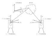
- a three-dimensional coordinate system (hereinafter referred to as a local coordinate system) is set inside a laser measuring apparatus, and three-dimensional coordinate data including three-dimensional coordinates (X, Y, Z) of the external world is measured in the coordinate system.
- three-dimensional coordinate data is measured in a coordinate system installed in each laser measuring device.
- the local coordinate system XYZ is set for the laser measurement device A
- the local coordinate system X'Y'Z ' is set for the laser measurement device B
- the world coordinate system XwYwZw is set for the outside world
- the three-dimensional coordinate data of the world coordinate system is set.
- This is called reference point survey or reference point measurement.
- three-dimensional coordinate data (reference point) in the world coordinate system is measured by each laser measuring device.
- each of the three-dimensional coordinate data obtained by each laser measuring device is converted into three-dimensional coordinate data in the world coordinate system. .
- synthesis of three-dimensional coordinate data using such reference points is used.
- the conversion of the three-dimensional coordinate system performed at this time includes a three-dimensional rotation conversion and a translation conversion.
- Non-Patent Document 1 describes a method of calculating a three-dimensional rotation conversion and a translation amount from three-dimensional coordinate data of a given reference point
- Non-Patent Document 2 describes a method of calculating a three-dimensional coordinate obtained by a laser measurement device. A method for adjusting the position of the acquired three-dimensional coordinate data is described on the assumption that a correct three-dimensional shape model is provided for the three-dimensional coordinates.
- Non-Patent Document 3 describes a calibration method using a two-dimensional plane pattern.
- Non-Patent Document 1 when three-dimensional coordinate data is measured using a laser measurement device A and a laser measurement device B, one local coordinate system (the three-dimensional coordinate system of the laser measurement device B) is used. ) Is rigidly transformed into another local coordinate system (the three-dimensional coordinate system of the laser measurement device A).
- a three-dimensional rotation matrix and a three-dimensional translation vector between the three-dimensional coordinate systems are configured, and the three-dimensional coordinate data measured by the two laser measurement devices is synthesized on the same coordinate system by the rigid transformation.
- ⁇ Rigid body transformation from one three-dimensional coordinate system to another three-dimensional coordinate system is equivalent to obtaining the orientation and position of each local coordinate system in the world coordinate system.
- Non-Patent Document 1 In using the method of Non-Patent Document 1, it is necessary to measure the same point in space with the laser measurement device A and the laser measurement device B, respectively. Naturally, in order to obtain an accurate rigid transformation, not only one point but many pairs of three-dimensional points such as 100 points are required.
- the task of identifying the same point from the three-dimensional coordinate data measured by the laser is a little troublesome, and the exact same point is identified due to the limitation of the spatial resolution of the laser measurement. There is a problem that it is not easy to do.
- Non-Patent Document 2 discloses an Iterative Closest Point (ICP) algorithm for automatically aligning two point cloud data.
- ICP Iterative Closest Point
- the ICP algorithm can accurately match the positions of two point groups by repeating corresponding point search and rigid body transformation estimation.
- the present invention has been made in view of the above points, and provides a measurement calibration device, a measurement calibration method, and a program that can easily estimate the position and orientation of a local coordinate system in a laser measurement device with respect to a world coordinate system.
- the purpose is to do.
- the measuring and calibrating apparatus is characterized in that the three-dimensional coordinate data of a specific object is obtained by a laser measuring apparatus that measures three-dimensional coordinate data including the three-dimensional coordinates of each of a plurality of points on the object.
- a distance image generation unit that generates a distance image representing a distance to the specific object, for each of the plurality of position and orientation, based on the three-dimensional coordinate data of the specific object for each of a plurality of position and orientation, For each of the distance images for each of the plurality of positions and orientations generated by the distance image generation unit, a corner point that is a point at which the density of the distance image changes is detected, and a corresponding corner point between the distance images is detected.
- a corresponding point detecting unit that detects a certain corresponding point, the detected corresponding point, and the three-dimensional coordinates obtained from the three-dimensional coordinate data at a reference position and orientation among the plurality of positions and orientations.
- the reference coordinates that are the three-dimensional coordinates of each point on the specific object in the system
- two points of each point on the world coordinate system are used.
- a plane projection transformation matrix for performing plane projection transformation between two-dimensional coordinates and two-dimensional coordinates on the distance image is calculated.Based on the plane projection transformation matrix, a unique And a posture / position calculation unit that calculates the position and posture of the local coordinate system, which is a coordinate system.
- the distance image generation unit is obtained by a laser measurement device that measures three-dimensional coordinate data including three-dimensional coordinates of the plurality of points on the object, A distance image representing the distance to the specific object, for each of the plurality of positions and postures, based on the three-dimensional coordinate data of the specific object for each of the plurality of positions and postures; Generating, the corresponding point detecting unit detects, for each of the distance images for each of the plurality of position and orientation generated by the distance image generating unit, a corner point that is a point at which the shading of the distance image changes, A corresponding point which is a corner point corresponding between the distance images is detected, and a posture / position calculation unit calculates the three-dimensional position in the detected corresponding point and a reference position / posture among the plurality of position / postures.
- a plane projection transformation matrix for performing plane projection transformation between the two-dimensional coordinates of each point of the coordinate system and the two-dimensional coordinates on the distance image is calculated, and based on the plane projection transformation matrix, The position and orientation of a local coordinate system, which is a unique coordinate system of the laser measurement device, are calculated.
- the distance image generation unit uses a laser measurement device that measures three-dimensional coordinate data including the three-dimensional coordinates of each of a plurality of points on the object. Based on the obtained three-dimensional coordinate data of the specific object, based on the three-dimensional coordinate data of the specific object for each of the plurality of positions and orientations, generate a distance image representing the distance to the specific object for each of the plurality of positions and orientations. Then, for each of the distance images for each of the plurality of positions and orientations generated by the distance image generation unit, the corresponding point detection unit detects a corner point where the shading of the distance image changes, and the correspondence between the distance images is detected. The corresponding point which is the corner point to be detected is detected.
- the posture / position calculation unit calculates the three-dimensional position of each point on the specific object in the world coordinate system, which is obtained from the detected corresponding point and three-dimensional coordinate data at a reference position / posture among the plurality of position / postures. Based on the reference coordinates of the points on the specific object corresponding to the corresponding point, the two-dimensional coordinates of each point in the world coordinate system and the two-dimensional coordinates A plane projection transformation matrix for performing plane projection transformation with the dimensional coordinates is calculated, and the position and orientation of the local coordinate system, which is a unique coordinate system of the laser measurement apparatus with respect to the world coordinate system, based on the plane projection transformation matrix. Is calculated.
- the specific object is obtained for each of the plurality of positions and orientations.
- a distance image representing the distance of the distance image is generated, and for each of the distance images for each of the plurality of positions and orientations, a corner point at which the shading of the distance image changes is detected, and a corresponding corner point between the distance images is detected. It is a three-dimensional coordinate of each point on a specific object in the world coordinate system, which is obtained from a detected corresponding point and three-dimensional coordinate data at a reference position and orientation among a plurality of positions and orientations.
- planar projection transformation is performed between the two-dimensional coordinates of each point in the world coordinate system and the two-dimensional coordinates on the distance image.
- Projective transformation for By calculating the column and calculating the position and orientation of the local coordinate system, which is a unique coordinate system of the laser measurement device with respect to the world coordinate system, based on the plane projection transformation matrix, the local measurement in the laser measurement device with respect to the world coordinate system The position and orientation of the coordinate system can be easily estimated.
- the measurement and calibration device measures the position of the laser measurement device based on the position and orientation of the local measurement system of the laser measurement device with respect to the world coordinate system calculated by the orientation and position calculation unit.
- the image processing apparatus may further include a three-dimensional conversion unit configured to convert the dimensional coordinate data into the world coordinate system.
- the measurement and calibration device further includes, for each of the plurality of positions and orientations, a captured image acquisition unit that acquires a captured image representing the specific object obtained by an imaging device, and the corresponding point detection unit includes: Further, for each of the captured images for each of the plurality of positions and orientations, a second corner point at which a pixel value of the captured image changes is detected, and a second corner point corresponding to the captured image is detected. A second corresponding point is detected, and the posture / position calculation unit further calculates the second corresponding point based on the detected second corresponding point and the reference coordinates of a point on the specific object corresponding to the second corresponding point.
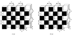
- the specific object of the measurement and calibration apparatus is such that, on the near side, rectangular parallelepipeds having a width w, a height h, and a depth d are arranged at intervals of w in the horizontal direction, and at intervals of h in the vertical direction. It can be configured such that the surface shape on the near side is arranged in a checkered pattern when viewed from the front.
- a program according to the present invention is a program for functioning as each unit of the above-described measurement and calibration device.
- the position and orientation of the local coordinate system in the laser measurement device with respect to the world coordinate system can be easily estimated.
- FIG. 1 is a block diagram illustrating a configuration of a measurement and calibration device according to a first embodiment of the present invention. It is an image figure showing an example of the specific object concerning a 1st embodiment of the present invention. It is an image figure showing an example of the specific object concerning a 1st embodiment of the present invention. It is an image figure showing the example of the distance picture concerning a 1st embodiment of the present invention. It is an image figure showing an example of corresponding point detection concerning a 1st embodiment of the present invention.
- 5 is a flowchart illustrating a measurement calibration processing routine of the measurement calibration device according to the first embodiment of the present invention. 5 is a flowchart illustrating a distance image generation processing routine of the measurement and calibration device according to the first embodiment of the present invention.
- 5 is a flowchart illustrating a corresponding point detection processing routine of the measurement and calibration device according to the first embodiment of the present invention.
- 5 is a flowchart illustrating a posture / position calculation processing routine of the measurement / calibration device according to the first embodiment of the present invention.
- 5 is a flowchart illustrating a three-dimensional coordinate conversion processing routine of the measurement and calibration device according to the embodiment of the present invention. It is a block diagram showing the composition of the measurement calibration device concerning a 2nd embodiment of the present invention. It is an image figure showing an example of the specific object concerning a 2nd embodiment of the present invention.
- 9 is a flowchart illustrating a distance image generation processing routine of the measurement and calibration device according to the second embodiment of the present invention.
- 9 is a flowchart illustrating a corresponding point detection processing routine of the measurement and calibration device according to the second embodiment of the present invention.
- 9 is a flowchart illustrating a posture / position calculation processing routine of the measurement / calibration device according to the second embodiment of the present invention.
- It is a block diagram showing the composition of the measurement calibration device concerning a 3rd embodiment of the present invention. It is an image figure showing an example of the specific object concerning a 3rd embodiment of the present invention.
- It is a block diagram showing the composition of the measurement calibration device concerning a 4th embodiment of the present invention.
- FIG. 7 is a diagram showing an example of registration of a laser measurement device according to the related art.
- the three-dimensional coordinate data (a set of three-dimensional coordinates on the local coordinate system XYZ) including the three-dimensional coordinates for each of a plurality of points on the object obtained by measuring the three-dimensional object by the laser measurement device is stored in the two-dimensional coordinate system It can be converted to dimensional coordinate data.
- the coordinates of the world coordinate system XwYwZw of the three-dimensional object (x w, y w, z w) in the two-dimensional coordinates (x w, y w) includes a two-dimensional coordinate ⁇ u, v
- the three-dimensional coordinate data obtained by measuring the three-dimensional object by the laser measuring device is converted into a distance image.
- a point corresponding to a three-dimensional object is detected from the distance image, and a two-dimensional coordinate of a corresponding point on the distance image and a two-dimensional coordinate of the three-dimensional object on a world coordinate system are projected onto a plane.
- a three-dimensional translation vector T representing the origin position of the local coordinate system with respect to the world coordinate system and a rotation matrix representing the orientation of the local coordinate system with respect to the world coordinate system Is calculated.
- the present invention it is possible to easily estimate the position and orientation of the laser measuring device in the local coordinate system in the world coordinate system only by measuring a specific three-dimensional object.
- those point cloud data can be synthesized in the world coordinate system, and the entire peripheral shape of the three-dimensional object can be obtained.
- 3D coordinate data can be obtained, and computer graphics such as movie production or program production, as well as real virtual reality and augmented reality with an actual environment can be produced. .
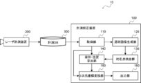
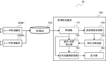
- FIG. 1 is a block diagram illustrating a configuration of a measurement system 10 according to the first embodiment of the present invention.
- the measurement system 10 includes a measurement calibration device 100, a laser measurement device 200, and a measurement database (DB) 300.
- DB measurement database
- the laser measuring device 200 measures, for each of a plurality of points on the object, three-dimensional coordinate data including the three-dimensional coordinates of the point.
- the laser measurement device 200 measures three-dimensional coordinate data of a specific object.
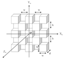
- FIG. 2 a three-dimensional object shown in FIG. 2 is measured as an example of the specific object.
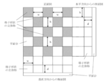
- FIG. 3 shows a front view of the specific object and cross-sectional views in the horizontal direction and the vertical direction.
- rectangular parallelepipeds having a width w, a height h, and a depth d are arranged on the near side at an interval of w in the horizontal direction and at an interval of h in the vertical direction.
- an Xw axis is defined in the horizontal direction
- a Yw axis is defined in the vertical direction
- a Zw axis is defined in a direction orthogonal to the two axes
- the origin is predetermined.
- the XwYwZw coordinate system having the center O of the obtained specific object is set as a world coordinate system (FIG. 2).
- the laser measurement device 200 changes the position and orientation of the specific object and measures the three-dimensional coordinate data of the specific object for each of the S (S is a natural number of 2 or more) position and orientation in the local coordinate system XYZ of the laser measurement device 200. I do.
- the three-dimensional coordinate data includes, for each of a plurality of points on the specific object, the three-dimensional coordinates (X, Y, Z) of the point. It is assumed that the S positions and orientations include a position and orientation as a reference for the specific object.
- the laser measurement device 200 obtains the three-dimensional coordinates of the specific object by using the measurement center of the laser measurement device 200 as the origin and using a local coordinate system set in the laser measurement device.
- the S positions and orientations of the specific object may include those where only the position is changed and those where only the orientation is changed.
- the laser measuring apparatus 200 stores all of the measured three-dimensional coordinate data of the specific object for each of the S positions and orientations in the measurement DB 300.
- the measurement DB 300 includes reference coordinates, which are three-dimensional coordinates of each point in the world coordinate system at a position and orientation serving as a reference of the specific object, and three-dimensional coordinate data of the specific object measured by the laser measurement device 200, 3D coordinate data for each of the S positions and orientations in the local coordinate system XYZ are stored.
- the measurement DB 300 stores reference coordinates, which are three-dimensional coordinates of each point on the specific object in the world coordinate system, obtained from the three-dimensional coordinate data of the specific object at the reference position and orientation.
- the measurement and calibration apparatus 100 is configured by a computer including a CPU, a RAM, and a ROM that stores a program for executing a measurement and calibration processing routine to be described later, and is functionally configured as follows. .
- the measurement and calibration device 100 includes an acquisition unit 110, a distance image generation unit 120, a corresponding point detection unit 130, a posture / position calculation unit 140, and a three-dimensional coordinate conversion unit. 150 and an output unit 160.
- the acquisition unit 110 obtains, from the measurement DB 300, reference coordinates that are three-dimensional coordinates of each point in the world coordinate system at a position and orientation serving as a reference of the specific object, and S position and orientation measured by the laser measurement device 200. Acquire three-dimensional coordinate data of a specific object.
- the acquisition unit 110 then sends the three-dimensional coordinate data for each of the S positions and orientations measured by the laser measurement device 200 to the distance image generation unit 120, the reference coordinates of the specific object to the orientation / position calculation unit 140, and the specific object And the three-dimensional coordinate data for each of the S positions and orientations measured by the laser measuring device 200 are passed to the three-dimensional coordinate conversion unit 150.
- the distance image generation unit 120 calculates the distance to the specific object for each of the S positions and postures based on the three-dimensional coordinate data of the specific object for each of the S positions and postures obtained by the laser measurement device 200. Generate a distance image to represent.
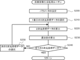
- distance image generation section 120 first sets parameter f for generating a distance image.
- the distance image generation unit 120 generates a distance image for each of the S position and orientation obtained by the laser measurement device 200, based on the three-dimensional coordinate data of the position and orientation.
- the distance image is an image representing the distance to the object, and is a perspective projection image in which the depth distance is visualized in black and white shading or the like.
- Equation (1) corresponds to perspective projection of the camera, and the parameter f corresponds to the focal length of the range image.
- the distance image generation unit 120 calculates the distance L from the laser measurement device to each point using the following equation (2), and quantizes the value from a value 0 to a value 255 according to the value of the distance L. A gray value g of the distance image is calculated.
- the gray value g of v) is calculated.
- the distance image generation unit 120 similarly calculates the gray value g of the two-dimensional coordinate data (u, v) for all three-dimensional coordinates (X, Y, Z) included in the three-dimensional coordinate data of the position and orientation. Thereby, a distance image representing the distance to the specific object in the three-dimensional coordinate data of the position and orientation is generated.
- the distance image generation unit 120 generates a distance image for each of the other position and orientation based on the three-dimensional coordinate data of the position and orientation. That is, distance image generating section 120 obtains S distance images shown in FIG.
- the distance image generation unit 120 passes the distance images for each of the S positions and orientations to the corresponding point detection unit 130.
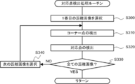
- the corresponding point detection unit 130 detects, for each of the distance images for each of the plurality of positions and orientations generated by the distance image generation unit 120, a corner point where the shading of the distance image changes, and performs correspondence between the distance images.
- the corresponding point which is the corner point to be detected is detected.
- the corresponding point detection unit 130 first detects black and white corner points of the first distance image.
- FIG. 5 shows an example of corner point detection.
- ⁇ ⁇ In an example of camera calibration using a two-dimensional plane pattern known in Non-Patent Document 3, such a black and white image is used.
- the corresponding point detection unit 130 detects corner points using a conventional image processing method by converting the three-dimensional coordinate data into a distance image.
- the corresponding point detection unit 130 passes all detected corresponding points to the posture / position calculation unit 140.
- the posture / position calculation unit 140 calculates the two-dimensional coordinates of each point on the world coordinate system and the distance image on the distance image based on the corresponding point in each distance image and the reference coordinates of a point on the specific object corresponding to the corresponding point.
- a plane projection transformation matrix for performing plane projection transformation between two-dimensional coordinates and the plane projection transformation matrix ,
- the position and orientation of the local coordinate system XYZ which is a unique coordinate system of the laser measurement device 200 with respect to the world coordinate system, are calculated.
- the posture / position calculation unit 140 firstly sets the reference coordinates (Xw, Yw, Yw, Yw, Yw, Zw), two-dimensional coordinates (Xw, Yw) of each point in the world coordinate system are obtained.
- the posture / position calculation unit 140 calculates the two-dimensional coordinates (u, v) of the corresponding points in each distance image and the two-dimensional coordinates (Xw of the reference coordinates) among the corresponding points obtained by the corresponding point detection unit 130. , Yw) to the plane projection transformation matrix Ask for.
- a two-dimensional coordinate (u, v) of the corresponding point obtained by the corresponding point detection unit 130 and a two-dimensional coordinate (Xw, Yw) of the reference coordinate have a relationship of plane-projection transformation (plane-homography). That's why.
- Plane projection transformation is perspective projection of a plane object given by the following equation (3), as shown in Non-Patent Document 3.
- ⁇ is a scale factor
- H is a 3 ⁇ 3 plane projective transformation matrix
- the posture / position calculation unit 140 calculates the plane projection transformation matrix for performing the plane projection transformation according to Expression (3). Is estimated.
- the posture / position calculator 140 calculates the estimated plane projection transformation matrix.
- the orientation of the local coordinate system with respect to the world The origin of the local coordinate system with respect to the world coordinate system
- Rotation matrix I is a 3 ⁇ 3 matrix, and is expressed as the following equation (4) using three-dimensional vectors r 1 , r 2 , and r 3 .
- Plane transformation matrix Rotation matrix
- Three-dimensional translation vector Has the following relationship (5) in the plane projection transformation relationship.
- the posture / position calculation unit 140 calculates the three-dimensional vectors r 1 and r 2 constituting the rotation matrix and the three-dimensional translation vector Is calculated by the following equation (6).
- the posture / position calculator 140 calculates the rotation matrix Another vector r 3 constituting the, determined by the following equation (7).
- equation (7) Represents the cross product of vectors.
- the posture / position calculator 140 calculates the calculated rotation matrix.
- the three-dimensional coordinate conversion unit 150 calculates the three-dimensional coordinates newly measured by the laser measurement device 200 based on the position and orientation of the laser measurement device 200 in the local coordinate system with respect to the world coordinate system calculated by the orientation / position calculation unit 140. Convert the data to the world coordinate system.
- the three-dimensional coordinate conversion unit 150 is a rotation matrix that indicates the position and orientation of the local coordinate system of the laser measurement device 200 with respect to the world coordinate system calculated by the orientation / position calculation unit 140 , And three-dimensional translation vector Is used to convert the three-dimensional coordinates (X, Y, Z) of the three-dimensional coordinate data measured by the laser measurement device 200 into three-dimensional coordinates (Xw, Yw, Zw) in the world coordinate system.
- the three-dimensional coordinate conversion unit 150 passes the three-dimensional coordinate data measured by the laser measurement device 200 converted to the world coordinate system to the output unit 160.
- the output unit 160 outputs the three-dimensional coordinate data measured by the laser measurement device 200 converted into the world coordinate system.
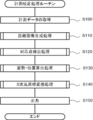
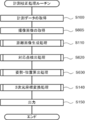
- FIG. 6 is a flowchart illustrating a measurement calibration processing routine according to the embodiment of the present invention.
- the three-dimensional coordinate data of the specific object in each of the S positions and orientations in the local coordinate system XYZ of the laser measurement device 200 is measured by the laser measurement device 200 while changing the position and orientation of the specific object.
- the measurement calibration apparatus 100 executes a measurement calibration processing routine shown in FIG.
- step S100 the acquisition unit 110 acquires three-dimensional coordinate data for each of the S positions and orientations measured by the laser measurement device 200.
- reference coordinates which are three-dimensional coordinates of each point on the specific object in the world coordinate system, are obtained from the three-dimensional coordinate data of the specific object at the reference position and orientation.
- step S110 the distance image generation unit 120 generates the specific object for each of the S positions and postures based on the three-dimensional coordinate data of the specific object for each of the S positions and postures obtained by the laser measurement device 200. Generate a distance image representing the distance to.
- step S120 the corresponding point detection unit 130 detects, for each of the distance images for each of the plurality of positions and orientations generated in step S110, a corner point at which the shading of the distance image changes, and determines the distance between the distance images.
- the corresponding point which is the corresponding corner point is detected.
- step S130 the posture / position calculation unit 140 calculates the two-dimensional coordinates and distance of each point in the world coordinate system based on the corresponding point in each distance image and the reference coordinates of the point of the specific object corresponding to the corresponding point.
- a plane projection transformation matrix for performing plane projection transformation between two-dimensional coordinates on an image and the plane projection transformation matrix , are calculated.
- step S140 the three-dimensional coordinate conversion unit 150 uses the three-dimensional coordinates newly measured by the laser measurement device 200 based on the position and orientation of the local coordinate system of the laser measurement device 200 with respect to the world coordinate system calculated in step S130. Convert the coordinate data to the world coordinate system.
- step S150 the output unit 160 outputs the three-dimensional coordinate data measured by the laser measurement device 200 converted into the world coordinate system.
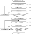
- step S110 the distance image generation processing routine in step S110 will be described with reference to FIG.
- step S200 distance image generating section 120 sets parameter f for generating a distance image.
- step S210 the distance image generation unit 120 selects the first three-dimensional coordinate data from the three-dimensional coordinate data of the specific object for each of the S positions and orientations obtained by the laser measurement device 200.
- step S220 the distance image generation unit 120 calculates the two-dimensional coordinates (u, v) from the three-dimensional coordinates (X, Y, Z) of each point of the selected three-dimensional coordinate data using the above equation (1). ) Is calculated.
- step S230 the distance image generation unit 120 calculates a distance L to each point of the three-dimensional coordinate data selected from the laser measurement device using the above equation (2), and calculates a value according to the value of the distance L.
- the gray value g of the distance image is calculated by quantizing from 0 to a value of 255.
- step S240 the distance image generation unit 120 determines whether all three-dimensional coordinate data has been processed.
- step S250 distance image generation section 120 selects the next three-dimensional coordinate data, and returns to step S220.
- step S240 if all three-dimensional coordinate data has been processed (YES in step S240), the process returns.
- step S120 the corresponding point detection processing routine in step S120 will be described with reference to FIG.
- step S300 the corresponding point detection unit 130 selects the first distance image from the distance images for each of the plurality of positions and orientations generated in step S110.
- step S310 the corresponding point detection unit 130 detects a corner point of the selected distance image.
- step S320 the corresponding point detection unit 130 checks whether or not the corner point corresponds to the corner point detected in the distance image in which the corner point has already been detected. .
- step S330 the corresponding point detection unit 130 determines whether or not all the distance images have been processed.
- step S340 the corresponding point detection unit 130 selects the next distance image and returns to step S310.
- step S330 if all the distance images have been processed (YES in step S330), the process returns.
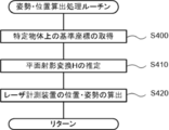
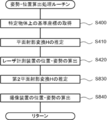
- the posture / position calculation unit 140 calculates the two-dimensional coordinates of each point in the world coordinate system and the distance image on the distance image based on the corresponding point in each distance image and the reference coordinates of each point on the specific object corresponding to the corresponding point.
- Projection transformation matrix for projective transformation between two-dimensional coordinates and the plane projection transformation matrix ,
- the position and orientation of the local coordinate system XYZ which is a unique coordinate system of the laser measurement device 200 with respect to the world coordinate system, are calculated.
- step S400 for each corresponding point, the posture / position calculation unit 140 acquires the reference coordinates of a point on the specific object corresponding to the corresponding point.
- step S410 the posture / position calculation unit 140 determines the two-dimensional coordinates of each point in the world coordinate system and the distance image based on each corresponding point and the reference coordinates of a point on the specific object corresponding to the corresponding point. Projection transformation matrix for performing plane projection transformation between two-dimensional coordinates of Is calculated.
- step S420 the posture / position calculator 140 calculates the plane projection transformation matrix calculated in step S410.
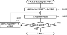
- step S140 the three-dimensional coordinate conversion processing routine in step S140 will be described with reference to FIG.
- the three-dimensional coordinate conversion unit 150 converts the three-dimensional coordinate data newly measured by the laser measurement device 200 based on the position and orientation of the local coordinate system of the laser measurement device 200 with respect to the world coordinate system calculated in step S130. Convert to world coordinate system.
- step S500 the three-dimensional coordinate conversion unit 150 selects the first three-dimensional coordinate data from the three-dimensional coordinate data of the specific object for each of the S positions and orientations obtained by the laser measurement device 200.
- step S510 the three-dimensional coordinate conversion unit 150 converts the selected three-dimensional coordinate data into world coordinates based on the position and orientation of the laser measurement device 200 in the local coordinate system with respect to the world coordinate system calculated in step S130. Convert to system.
- step S520 the three-dimensional coordinate conversion unit 150 determines whether to stop the process.
- step S530 the three-dimensional coordinate conversion unit 150 selects the next three-dimensional coordinate data, and returns to step S510.
- step S520 if all three-dimensional coordinate data has been processed (YES in step S520), the process returns.
- the three-dimensional coordinate data of the specific object obtained by the laser measurement device Based on the coordinate data, a distance image representing a distance to a specific object is generated for each of the plurality of position / postures. For each of the distance images for each of the plurality of position / postures, a corner at which the shading of the distance image changes Detecting a point, detecting a corresponding point that is a corner point corresponding between the distance images, and calculating the detected corresponding point and three-dimensional coordinate data at a reference position and orientation among a plurality of positions and orientations.
- Two-dimensional coordinates of each point in the world coordinate system based on reference coordinates of points on the specific object corresponding to the corresponding point among reference coordinates that are three-dimensional coordinates of each point on the specific object in the world coordinate system. And on the distance image A plane projection transformation matrix for performing plane projection transformation with the dimensional coordinates is calculated, and the position and orientation of the local coordinate system, which is a unique coordinate system of the laser measurement apparatus with respect to the world coordinate system, based on the plane projection transformation matrix. , The position and orientation of the local coordinate system in the laser measurement device with respect to the world coordinate system can be easily estimated.
- FIG. 11 is a block diagram showing the configuration of the measurement system 20 according to the second embodiment of the present invention.
- the measurement and calibration device 500 calibrates both the laser measurement device 200 and the imaging device 400.
- the measurement system 10 includes a laser measurement device 200, a measurement database (DB) 310, an imaging device 400, and a measurement calibration device 500.
- DB measurement database
- a three-dimensional object shown in FIG. 12 is measured as an example of the specific object.
- the front view of the specific object and the cross-sectional views in the horizontal direction and the vertical direction are the same as those in FIG. 3, but in the specific object, the front surface is black, and the other surfaces such as the back surface are It is white.
- the specific object has a rectangular parallelepiped having a width w, a height h, and a depth d on the near side arranged at an interval of w in the horizontal direction and an interval of h in the vertical direction, and has a front surface when viewed from the front.
- the object has a checkerboard shape.
- an Xw axis is defined in the horizontal direction
- a Yw axis is defined in the vertical direction
- a Zw axis is defined in a direction orthogonal to the two axes
- the origin is set at the center of the specific object.
- the XwYwZw coordinate system set to O is set as the world coordinate system (FIG. 12).
- the imaging device 400 changes the position and orientation of the specific object, shoots the specific object with a camera or the like, and generates S captured images.
- S which is the number of positions and orientations, may be a value different from that of the laser measurement device 200.
- the imaging device 400 stores the generated S captured images in the measurement DB 310.
- the measurement DB 310 is, similarly to the measurement DB 300 according to the first embodiment, three-dimensional coordinate data of a specific object measured by the laser measurement device 200, and is provided for each of S positions and orientations in the local coordinate system XYZ.
- the three-dimensional coordinate data is stored.
- the measurement DB 310 stores reference coordinates, which are three-dimensional coordinates of each point on the specific object in the world coordinate system, obtained from the three-dimensional coordinate data of the specific object at the reference position and orientation.
- the measurement DB 310 further stores captured images for each of the S positions and orientations obtained by the imaging device 400.
- the measurement and calibration device 500 is configured by a computer including a CPU, a RAM, and a ROM that stores a program for executing a measurement and calibration processing routine to be described later, and is functionally configured as follows. .
- the measurement calibration device 500 includes a captured image acquisition unit 510, a distance image generation unit 120, a corresponding point detection unit 530, a posture / position calculation unit 540, and three-dimensional coordinates. It is configured to include a conversion unit 150 and an output unit 560.
- the captured image acquisition unit 510 measures, from the measurement DB 310, reference coordinates that are three-dimensional coordinates of each point in the world coordinate system at a position and orientation that is a reference of the specific object, and measures the laser measurement device 200 The obtained three-dimensional coordinate data of the specific object for each of the S positions and orientations is obtained.
- the captured image acquisition unit 510 acquires a captured image representing a specific object obtained by the imaging device 400 from the measurement DB 310 for each of a plurality of positions and orientations.
- the captured image acquisition unit 510 outputs the three-dimensional coordinate data for each of the S positions and orientations measured by the laser measurement device 200 to the distance image generation unit 120, the reference coordinates of the specific object to the orientation / position calculation unit 540, The reference coordinates of the specific object and the three-dimensional coordinate data for each of the S positions and orientations measured by the laser measurement device 200 are passed to the three-dimensional coordinate conversion unit 150.
- the captured image acquisition unit 510 passes the captured image representing the specific object obtained by the imaging device 400 to the corresponding point detection unit 530.
- the corresponding point detecting unit 530 is, for each of the plurality of distance images generated by the distance image generating unit 120, a corner point at which the shading of the distance image changes. Is detected, and a corresponding point that is a corresponding corner point between the distance images is detected.
- the corresponding point detection unit 530 further detects, for each of the captured images for each of the plurality of positions and orientations, a second corner point at which the pixel value of the captured image changes, and a corresponding second corner between the captured images. A second corresponding point, which is a point, is detected.
- the corresponding point detection unit 530 first detects a second corner point at which the pixel value of the first captured image changes.
- the imaging device 400 captures the three-dimensional object shown in FIG. 12, all the black surfaces can be observed as planar projection images. That is, similarly to the case where the distance image is obtained by the planar projection transformation from the three-dimensional coordinate data in the first embodiment, the imaging device 400 captures a monochrome pattern by the planar projection by imaging observation. Since the back surface is white, the captured image is an image like a checkered pattern shown in FIG.
- the corresponding point detection unit 530 detects the second corner point where the pixel values of black and white of such a captured image change, using a conventional image processing method.
- the corresponding point detection unit 530 similarly detects the second corner point in the next captured image.
- the corresponding point detection unit 530 checks whether or not the second corner point corresponds to the second corner point detected in the previous captured image.
- the corresponding point detection unit 530 performs this process on all the captured images, and among the obtained corresponding points, converts the two-dimensional coordinate data of the corresponding points corresponding to the grid points on the surface of each rectangular parallelepiped of the specific object into the second data. This is the detection result of the corresponding point.
- the corresponding point detection unit 530 passes all the detected corresponding points and the second corresponding points to the posture / position calculation unit 540.
- the posture / position calculation unit 540 like the posture / position calculation unit 140, based on the corresponding point in each distance image and the reference coordinates of a point on the specific object corresponding to the corresponding point, and uses the respective coordinates in the world coordinate system.
- a plane projection transformation matrix for performing plane projection transformation between the two-dimensional coordinates of the point and the two-dimensional coordinates on the range image and the plane projection transformation matrix ,
- the position and orientation of the local coordinate system XYZ which is a unique coordinate system of the laser measurement device 200 with respect to the world coordinate system, are calculated.
- the posture / position calculation unit 540 further calculates, based on the detected second corresponding point and the reference coordinates of a point on the specific object corresponding to the second corresponding point, two points of the world coordinate system.
- Second plane projection transformation matrix for performing plane projection transformation between two-dimensional coordinates and two-dimensional coordinates on a captured image Is calculated, and a second plane projective transformation matrix is calculated.
- the position and orientation of the second local coordinate system which is a unique coordinate system of the imaging device 400 with respect to the world coordinate system, are calculated.
- the posture / position calculation unit 540 determines the two-dimensional coordinates (u, v) of the second corresponding point in each captured image among the second corresponding points obtained by the corresponding point detection unit 530, and the reference coordinates. From the two-dimensional coordinates (Xw, Yw) in accordance with the above equation (3). Is estimated.
- the posture / position calculator 540 calculates the estimated second plane projection transformation matrix.
- the orientation of the local coordinate system with respect to the world The origin of the local coordinate system with respect to the world coordinate system
- Rotation matrix I is a 3 ⁇ 3 matrix, and is represented as the above equation (4) using three-dimensional vectors r 1 , r 2 , and r 3 .
- the posture / position calculation unit 540 calculates the three-dimensional vectors r 1 and r 2 constituting the rotation matrix and the three-dimensional translation vector based on the relationship of the above equation (5). Are obtained by the above equation (6).
- the posture / position calculation unit 540 calculates the rotation matrix Another vector r 3 constituting the obtained by the equation (7).
- the posture / position calculator 540 calculates the calculated rotation matrix of the laser measurement device 200.
- the posture / position calculation unit 540 calculates the calculated rotation matrix of the imaging device 400. , And three-dimensional translation vector Is passed to the output unit 560.
- the output unit 560 outputs the three-dimensional coordinate data measured by the laser measurement device 200 converted into the world coordinate system. Further, the output unit 560 is a rotation matrix of the imaging device 400. , And three-dimensional translation vector Is output.
- FIG. 13 is a flowchart illustrating a measurement calibration processing routine according to the second embodiment of the present invention. Note that the same processes as those in the measurement calibration process routine according to the first embodiment are denoted by the same reference numerals, and detailed description is omitted.
- the measurement calibration device 500 executes a measurement calibration process routine shown in FIG.
- step S605 the captured image acquisition unit 510 acquires, from the measurement DB 310, a captured image representing the specific object obtained by the imaging device 400.
- the corresponding point detection unit 530 detects, for each of the distance images for each of the plurality of positions and orientations generated in step S110, a corner point where the shading of the distance image changes, and calculates the distance between the distance images.
- a second corner point that is a point at which the pixel value of the captured image changes is detected between the captured images.
- step S630 the posture / position calculation unit 540 determines the two-dimensional coordinates of each point in the world coordinate system based on the corresponding point in each distance image and the reference coordinates of a point on the specific object corresponding to the corresponding point.
- a plane projection transformation matrix for performing plane projection transformation between two-dimensional coordinates on a range image and the plane projection transformation matrix , are calculated.
- the two-dimensional coordinates of each point in the world coordinate system and the two-dimensional coordinates on the captured image are determined.
- Second plane projective transformation matrix for plane projective transformation between Is calculated, and a second plane projective transformation matrix is calculated.
- the position and orientation of the second local coordinate system which is a unique coordinate system of the imaging device 400 with respect to the world coordinate system, are calculated.
- step S620 the corresponding point detection processing routine in step S620 will be described with reference to FIG.
- step S750 the corresponding point detection unit 530 selects the first captured image among the captured images for each of the plurality of positions and orientations acquired in step S605.
- step S760 the corresponding point detection unit 530 detects the second corner point of the selected captured image.
- step S770 the corresponding point detection unit 530 checks whether or not the second corner point corresponds to the second corner point detected in the captured image in which the second corner point has already been detected, and determines whether or not the second corner point has the same position. If there is, it is detected as a second corresponding point.
- step S780 the corresponding point detection unit 530 determines whether or not all the captured images have been processed.
- step S790 the corresponding point detection unit 530 selects the next captured image, and returns to step S760.
- step S780 if all the captured images have been processed (YES in step S780), the process returns.
- step S630 the posture / position calculation processing routine in step S630 will be described with reference to FIG.
- step S830 the posture / position calculation unit 540 determines the two-dimensional coordinates of each point in the world coordinate system and the captured image on the basis of the corresponding point and the reference coordinates of a point on the specific object corresponding to the corresponding point. Projection transformation matrix for performing plane projection transformation between two-dimensional coordinates of Is calculated.
- step S840 the posture / position calculation unit 540 calculates the second plane projection transformation matrix calculated in step S830. , The position and orientation of the local coordinate system XYZ, which is a unique coordinate system of the imaging device 400 with respect to the world coordinate system, are calculated, and the process returns.
- a captured image representing a specific object obtained by the imaging device is acquired, and for each of the plurality of For each of the captured images, a second corner point where the pixel value of the captured image changes is detected, and a second corresponding point which is a second corner point corresponding between the captured images is detected and used as a reference.
- a second plane projection transformation matrix for performing plane projection transformation between the two-dimensional coordinates on the captured image is calculated, and based on the second plane projection transformation matrix, a unique coordinate system of the imaging apparatus with respect to the world coordinate system is used.
- the position and orientation of a certain second local coordinate system To exit, the position and orientation of the local coordinate system in the laser measuring device to the world coordinate system with easily estimate the position and orientation of the local coordinate system in the image pickup apparatus can be estimated simultaneously.
- FIG. 16 is a block diagram showing a configuration of a measurement system 30 according to the third embodiment of the present invention.
- the measurement system 30 includes the measurement calibration device 100, N laser measurement devices 200 # 1 to #N, and a measurement database (DB) 320.
- each unit of the measurement and calibration device 100 is the same as when one laser measurement device 200 is used.
- the three-dimensional coordinate data obtained by each laser measurement device 200 is stored in the measurement DB 320 while switching between the laser measurement devices 200 # 1 to 200 # N.
- reference coordinates which are three-dimensional coordinates of each point in the world coordinate system at a position and orientation serving as a reference of a specific object
- the measured three-dimensional coordinate data of the specific object, and three-dimensional coordinate data for each of the S positions and orientations in the local coordinate system XYZ are stored.
- the measurement DB 320 also includes reference coordinates, which are the three-dimensional coordinates of each point on the specific object in the world coordinate system, obtained from the three-dimensional coordinate data of the specific object at the reference position and orientation of each laser measurement device 200. Is stored.
- the three-dimensional object shown in FIG. 2 is used as the specific object, as in the first embodiment.
- the laser measuring devices 200 # 1 to 200 # N are arranged so as to surround the specific object, the three-dimensional object shown in FIG. 17 is used as the specific object.
- the specific object illustrated in FIG. 17 is an object in which rectangular parallelepipeds having a width w, a height h, and a depth d are arranged at intervals of w in the horizontal direction and at intervals of h in the vertical direction. Further, the specific object is configured such that the front surface and the rear surface have the same shape.
- the three-dimensional coordinate data of the specific object obtained by the laser measurement apparatus and the three-dimensional coordinate data of the specific object for each of a plurality of positions and orientations.
- a distance image representing the distance to the specific object is generated, and for each of the plurality of distance and orientation images, a corner point at which the shading of the distance image changes is determined.
- the two-dimensional coordinates and distance of each point on the world coordinate system 2D on the image A plane projection transformation matrix for performing plane projection transformation between the target and the target is calculated, and based on the plane projection transformation matrix, the position and orientation of the local coordinate system, which is a unique coordinate system of the laser measurement device with respect to the world coordinate system, are calculated.
- the three-dimensional coordinate data obtained by each of the plurality of laser measurement devices can be easily synthesized in the world coordinate system.
- FIG. 18 is a block diagram showing a configuration of a measurement system 40 according to the fourth embodiment of the present invention.
- the measurement system 40 includes a measurement / calibration device 500, N laser measurement devices 200 # 1 to #N, a measurement database (DB) 330, and M imaging devices 400 # 1 to #M. .
- each unit of the measurement and calibration device 500 is the same as the case where one laser measurement device 200 is used.
- the three-dimensional coordinates obtained by each laser measurement device 200 are stored in the measurement DB 330 while switching between the laser measurement devices 200 # 1 to 200 # N. Store the data.
- the captured image obtained by each imaging device 400 is stored in the measurement DB 330 while switching between the imaging devices 400 # 1 to 400 # M.
- reference coordinates which are three-dimensional coordinates of each point in the world coordinate system at a position and orientation serving as a reference of a specific object
- the measured three-dimensional coordinate data of the specific object, and three-dimensional coordinate data for each of the S positions and orientations in the local coordinate system XYZ are stored.
- the measurement DB 330 similarly to the measurement DB 320 according to the third embodiment, in the world coordinate system obtained from the three-dimensional coordinate data of the specific object at the reference position and orientation of each laser measurement device 200. Reference coordinates, which are three-dimensional coordinates of each point on the specific object, are stored.
- the three-dimensional object illustrated in FIG. 12 is used as the specific object.
- the laser measurement devices 200 # 1 to 200 # N and the M imaging devices 400 # 1 to #M are arranged so as to surround the specific object, the three-dimensional object shown in FIG. Use an object.
- the specific object shown in FIG. 19 is an object in which rectangular parallelepipeds having a width w, a height h, and a depth d are arranged at intervals of w in the horizontal direction and at intervals of h in the vertical direction.
- the specific object is configured so that the front and the back have the same shape, the front surface is black, and the back surface is white.
- a captured image representing a specific object obtained by the imaging device is acquired, and the captured images of the plurality of positions and orientations are acquired.
- a second corner point which is a point at which the pixel value of the captured image changes, is detected, and a second corresponding point, which is a second corner point corresponding between the captured images, is detected.
- a second plane projection transformation matrix for performing plane projection transformation between the two-dimensional coordinates is calculated, and a second local projection, which is a unique coordinate system of the imaging apparatus with respect to the world coordinate system, is calculated based on the second plane projection transformation matrix.
- the specific object is described on the front side as a rectangular parallelepiped having a width w, a height h, and a depth d arranged at an interval of w in the horizontal direction and at an interval of h in the vertical direction.
- the rectangular parallelepiped may be a cube.
- Data may be transferred between the processing units by using a recording medium such as a hard disk, a RAID device, or a CD-ROM, or by using a remote data resource via a network.
- a recording medium such as a hard disk, a RAID device, or a CD-ROM
- the embodiment has been described in which the program is installed in advance.
- the program may be stored in a computer-readable recording medium and provided.
Landscapes
- Physics & Mathematics (AREA)
- General Physics & Mathematics (AREA)
- Engineering & Computer Science (AREA)
- Radar, Positioning & Navigation (AREA)
- Remote Sensing (AREA)
- Length Measuring Devices By Optical Means (AREA)
Abstract
La présente invention permet d'estimer aisément l'emplacement et l'attitude d'un système de coordonnées locales pour un dispositif de mesure laser par rapport au système de coordonnées universelles. Selon la présente invention, sur la base de données de coordonnées tridimensionnelles pour un objet spécifique comme dans chacun d'une pluralité d'emplacements/attitudes, une unité de génération d'image de distance 120 qui génère des images de distance qui représentent la distance par rapport à l'objet spécifique comme dans la pluralité d'emplacements/attitudes. Une unité de détection de point correspondant 130 détecte des points correspondants qui, parmi des points de coin qui ont été détectés pour chacune des images de distance pour la pluralité d'emplacements/attitudes et sont des points auxquels le ton des images de distance change, sont des points qui correspondent entre des images de distance. Une unité de calcul d'attitude/emplacement 140 calcule l'emplacement et l'attitude d'un système de coordonnées individuelles pour un dispositif de mesure laser par rapport au système de coordonnées universelles sur la base d'une matrice qui est destinée à une transformation par projection plane entre des coordonnées bidimensionnelles sur l'image de distance pour un emplacement/attitude de référence et des coordonnées bidimensionnelles sur le système de coordonnées universelles et est calculée sur la base des points correspondants et de coordonnées de référence qui correspondent aux points correspondants parmi les coordonnées de référence qui sont des coordonnées tridimensionnelles pour chacun des points sur l'objet spécifique sur le système de coordonnées universelles, telles que déterminées à partir des données de coordonnées tridimensionnelles pour l'emplacement/attitude de référence.
Applications Claiming Priority (2)
| Application Number | Priority Date | Filing Date | Title |
|---|---|---|---|
| JP2018148804A JP2020024142A (ja) | 2018-08-07 | 2018-08-07 | 計測校正装置、計測校正方法、及びプログラム |
| JP2018-148804 | 2018-08-07 |
Publications (2)
| Publication Number | Publication Date |
|---|---|
| WO2020031950A1 true WO2020031950A1 (fr) | 2020-02-13 |
| WO2020031950A9 WO2020031950A9 (fr) | 2021-02-11 |
Family
ID=69413805
Family Applications (1)
| Application Number | Title | Priority Date | Filing Date |
|---|---|---|---|
| PCT/JP2019/030705 Ceased WO2020031950A1 (fr) | 2018-08-07 | 2019-08-05 | Dispositif d'étalonnage de mesure, procédé d'étalonnage de mesure et programme |
Country Status (2)
| Country | Link |
|---|---|
| JP (1) | JP2020024142A (fr) |
| WO (1) | WO2020031950A1 (fr) |
Cited By (6)
| Publication number | Priority date | Publication date | Assignee | Title |
|---|---|---|---|---|
| CN112033408A (zh) * | 2020-08-27 | 2020-12-04 | 河海大学 | 一种贴纸式的物体空间定位系统及定位方法 |
| CN113048938A (zh) * | 2021-03-04 | 2021-06-29 | 湖北工业大学 | 一种合作目标设计及姿态角测量系统及方法 |
| CN113483669A (zh) * | 2021-08-24 | 2021-10-08 | 凌云光技术股份有限公司 | 一种基于立体靶标的多传感器位姿标定方法及装置 |
| CN114543767A (zh) * | 2022-02-22 | 2022-05-27 | 中国商用飞机有限责任公司 | 用于飞机水平测量的系统和方法 |
| CN117284500A (zh) * | 2023-11-24 | 2023-12-26 | 北京航空航天大学 | 一种基于单目视觉和激光的盘绕式伸展臂位姿调整方法 |
| WO2024027634A1 (fr) * | 2022-08-01 | 2024-02-08 | 京东方科技集团股份有限公司 | Procédé et appareil d'estimation de distance de déplacement, dispositif électronique et support d'enregistrement |
Families Citing this family (4)
| Publication number | Priority date | Publication date | Assignee | Title |
|---|---|---|---|---|
| CN113465600B (zh) * | 2020-03-30 | 2024-05-28 | 浙江宇视科技有限公司 | 一种导航方法、装置及电子设备和存储介质 |
| CN111640177B (zh) * | 2020-05-26 | 2023-04-25 | 佛山科学技术学院 | 一种基于水下声呐探测的三维建模方法及无人潜水器 |
| CN114004741B (zh) * | 2021-08-31 | 2024-09-06 | 上海汇像信息技术有限公司 | 水平运动平台激光扫描标定模版的拼接方法 |
| CN115861047B (zh) * | 2021-09-23 | 2025-11-25 | 中移(上海)信息通信科技有限公司 | 一种遥感影像坐标系转换的控制方法、装置及终端 |
Citations (4)
| Publication number | Priority date | Publication date | Assignee | Title |
|---|---|---|---|---|
| JP2007017318A (ja) * | 2005-07-08 | 2007-01-25 | Taisei Corp | 基線測定システムおよび基線測定方法 |
| JP2007192585A (ja) * | 2006-01-17 | 2007-08-02 | Develo:Kk | 測量ユニットの較正方法および生産方法、ならびに移動体測量を行なうための装置の生産方法 |
| JP2009168472A (ja) * | 2008-01-10 | 2009-07-30 | Zenrin Co Ltd | レーザースキャナのキャリブレーション装置及びキャリブレーション方法 |
| JP2017122712A (ja) * | 2015-11-16 | 2017-07-13 | ジック アーゲー | レーザスキャナの調整方法 |
-
2018
- 2018-08-07 JP JP2018148804A patent/JP2020024142A/ja active Pending
-
2019
- 2019-08-05 WO PCT/JP2019/030705 patent/WO2020031950A1/fr not_active Ceased
Patent Citations (4)
| Publication number | Priority date | Publication date | Assignee | Title |
|---|---|---|---|---|
| JP2007017318A (ja) * | 2005-07-08 | 2007-01-25 | Taisei Corp | 基線測定システムおよび基線測定方法 |
| JP2007192585A (ja) * | 2006-01-17 | 2007-08-02 | Develo:Kk | 測量ユニットの較正方法および生産方法、ならびに移動体測量を行なうための装置の生産方法 |
| JP2009168472A (ja) * | 2008-01-10 | 2009-07-30 | Zenrin Co Ltd | レーザースキャナのキャリブレーション装置及びキャリブレーション方法 |
| JP2017122712A (ja) * | 2015-11-16 | 2017-07-13 | ジック アーゲー | レーザスキャナの調整方法 |
Cited By (8)
| Publication number | Priority date | Publication date | Assignee | Title |
|---|---|---|---|---|
| CN112033408A (zh) * | 2020-08-27 | 2020-12-04 | 河海大学 | 一种贴纸式的物体空间定位系统及定位方法 |
| CN112033408B (zh) * | 2020-08-27 | 2022-09-30 | 河海大学 | 一种贴纸式的物体空间定位系统及定位方法 |
| CN113048938A (zh) * | 2021-03-04 | 2021-06-29 | 湖北工业大学 | 一种合作目标设计及姿态角测量系统及方法 |
| CN113483669A (zh) * | 2021-08-24 | 2021-10-08 | 凌云光技术股份有限公司 | 一种基于立体靶标的多传感器位姿标定方法及装置 |
| CN114543767A (zh) * | 2022-02-22 | 2022-05-27 | 中国商用飞机有限责任公司 | 用于飞机水平测量的系统和方法 |
| WO2024027634A1 (fr) * | 2022-08-01 | 2024-02-08 | 京东方科技集团股份有限公司 | Procédé et appareil d'estimation de distance de déplacement, dispositif électronique et support d'enregistrement |
| CN117284500A (zh) * | 2023-11-24 | 2023-12-26 | 北京航空航天大学 | 一种基于单目视觉和激光的盘绕式伸展臂位姿调整方法 |
| CN117284500B (zh) * | 2023-11-24 | 2024-02-09 | 北京航空航天大学 | 一种基于单目视觉和激光的盘绕式伸展臂位姿调整方法 |
Also Published As
| Publication number | Publication date |
|---|---|
| JP2020024142A (ja) | 2020-02-13 |
| WO2020031950A9 (fr) | 2021-02-11 |
Similar Documents
| Publication | Publication Date | Title |
|---|---|---|
| WO2020031950A1 (fr) | Dispositif d'étalonnage de mesure, procédé d'étalonnage de mesure et programme | |
| JP5624394B2 (ja) | 位置姿勢計測装置、その計測処理方法及びプログラム | |
| JP7716712B2 (ja) | 三次元モデル生成方法、情報処理装置およびプログラム | |
| JP5393318B2 (ja) | 位置姿勢計測方法及び装置 | |
| JP4708752B2 (ja) | 情報処理方法および装置 | |
| JP5297403B2 (ja) | 位置姿勢計測装置、位置姿勢計測方法、プログラムおよび記憶媒体 | |
| JP5018980B2 (ja) | 撮像装置、長さ測定方法、及びプログラム | |
| JP5872923B2 (ja) | Ar画像処理装置及び方法 | |
| KR101715780B1 (ko) | 복셀 맵 생성기 및 그 방법 | |
| JP2019534510A5 (fr) | ||
| KR20110068469A (ko) | 메타정보 없는 단일 영상에서 3차원 개체정보 추출방법 | |
| JP5384316B2 (ja) | 変位計測装置、変位計測方法、及び変位計測プログラム | |
| JP2016217941A (ja) | 3次元データ評価装置、3次元データ測定システム、および3次元計測方法 | |
| JP5748355B2 (ja) | 3次元座標算出装置、3次元座標算出方法、及びプログラム | |
| JP2010239515A (ja) | カメラキャリブレーションの算出方法 | |
| JP2011022084A (ja) | 三次元姿勢測定装置および三次元姿勢測定方法 | |
| JP2023047882A (ja) | 画像生成装置、画像生成方法およびプログラム | |
| JP4701848B2 (ja) | 画像マッチング装置、画像マッチング方法および画像マッチング用プログラム | |
| JP6584139B2 (ja) | 情報処理装置、情報処理方法及びプログラム | |
| KR20110084477A (ko) | 메타정보 없는 단일 영상에서 3차원 개체정보 추출방법 | |
| JP2005063012A (ja) | 全方位カメラ運動と3次元情報の復元方法とその装置及びプログラム並びにこれを記録した記録媒体 | |
| JP2006300656A (ja) | 画像計測方法、装置、プログラム及び記録媒体 | |
| JP5359477B2 (ja) | 道路領域推定装置及びプログラム | |
| JP5230354B2 (ja) | 位置特定装置及び異動建物検出装置 | |
| JP5409451B2 (ja) | 3次元変化検出装置 |
Legal Events
| Date | Code | Title | Description |
|---|---|---|---|
| 121 | Ep: the epo has been informed by wipo that ep was designated in this application |
Ref document number: 19848547 Country of ref document: EP Kind code of ref document: A1 |
|
| NENP | Non-entry into the national phase |
Ref country code: DE |
|
| 122 | Ep: pct application non-entry in european phase |
Ref document number: 19848547 Country of ref document: EP Kind code of ref document: A1 |