WO2020031972A1 - Inducteur couplé et circuit de commutation - Google Patents
Inducteur couplé et circuit de commutation Download PDFInfo
- Publication number
- WO2020031972A1 WO2020031972A1 PCT/JP2019/030760 JP2019030760W WO2020031972A1 WO 2020031972 A1 WO2020031972 A1 WO 2020031972A1 JP 2019030760 W JP2019030760 W JP 2019030760W WO 2020031972 A1 WO2020031972 A1 WO 2020031972A1
- Authority
- WO
- WIPO (PCT)
- Prior art keywords
- core
- coupled inductor
- inductor
- joint
- phase
- Prior art date
- Legal status (The legal status is an assumption and is not a legal conclusion. Google has not performed a legal analysis and makes no representation as to the accuracy of the status listed.)
- Ceased
Links
Images


Classifications
-
- H—ELECTRICITY
- H01—ELECTRIC ELEMENTS
- H01F—MAGNETS; INDUCTANCES; TRANSFORMERS; SELECTION OF MATERIALS FOR THEIR MAGNETIC PROPERTIES
- H01F1/00—Magnets or magnetic bodies characterised by the magnetic materials therefor; Selection of materials for their magnetic properties
- H01F1/01—Magnets or magnetic bodies characterised by the magnetic materials therefor; Selection of materials for their magnetic properties of inorganic materials
- H01F1/03—Magnets or magnetic bodies characterised by the magnetic materials therefor; Selection of materials for their magnetic properties of inorganic materials characterised by their coercivity
- H01F1/12—Magnets or magnetic bodies characterised by the magnetic materials therefor; Selection of materials for their magnetic properties of inorganic materials characterised by their coercivity of soft-magnetic materials
- H01F1/14—Magnets or magnetic bodies characterised by the magnetic materials therefor; Selection of materials for their magnetic properties of inorganic materials characterised by their coercivity of soft-magnetic materials metals or alloys
- H01F1/20—Magnets or magnetic bodies characterised by the magnetic materials therefor; Selection of materials for their magnetic properties of inorganic materials characterised by their coercivity of soft-magnetic materials metals or alloys in the form of particles, e.g. powder
- H01F1/22—Magnets or magnetic bodies characterised by the magnetic materials therefor; Selection of materials for their magnetic properties of inorganic materials characterised by their coercivity of soft-magnetic materials metals or alloys in the form of particles, e.g. powder pressed, sintered, or bound together
- H01F1/24—Magnets or magnetic bodies characterised by the magnetic materials therefor; Selection of materials for their magnetic properties of inorganic materials characterised by their coercivity of soft-magnetic materials metals or alloys in the form of particles, e.g. powder pressed, sintered, or bound together the particles being insulated
-
- H—ELECTRICITY
- H01—ELECTRIC ELEMENTS
- H01F—MAGNETS; INDUCTANCES; TRANSFORMERS; SELECTION OF MATERIALS FOR THEIR MAGNETIC PROPERTIES
- H01F27/00—Details of transformers or inductances, in general
- H01F27/24—Magnetic cores
-
- H—ELECTRICITY
- H01—ELECTRIC ELEMENTS
- H01F—MAGNETS; INDUCTANCES; TRANSFORMERS; SELECTION OF MATERIALS FOR THEIR MAGNETIC PROPERTIES
- H01F27/00—Details of transformers or inductances, in general
- H01F27/24—Magnetic cores
- H01F27/255—Magnetic cores made from particles
-
- H—ELECTRICITY
- H01—ELECTRIC ELEMENTS
- H01F—MAGNETS; INDUCTANCES; TRANSFORMERS; SELECTION OF MATERIALS FOR THEIR MAGNETIC PROPERTIES
- H01F3/00—Cores, Yokes, or armatures
- H01F3/08—Cores, Yokes, or armatures made from powder
-
- H—ELECTRICITY
- H01—ELECTRIC ELEMENTS
- H01F—MAGNETS; INDUCTANCES; TRANSFORMERS; SELECTION OF MATERIALS FOR THEIR MAGNETIC PROPERTIES
- H01F37/00—Fixed inductances not covered by group H01F17/00
Definitions
- the present invention relates to a coupling inductor and a switching circuit having the coupling inductor.
- the interleave method has attracted attention as a circuit method for achieving high power density.
- the interleave method is a control method in which a power supply is divided into a plurality of systems, each phase has a phase difference, and ripples and the like are canceled each other. For example, in a two-phase interleaving method, a ripple is offset by giving a 180 ° phase difference to the current phase. By employing the interleaving method, it is possible to reduce the size and weight of the output smoothing capacitor and to reduce the ripple.
- the interleave method the number of components of the inductor increases, so that there is a limit in increasing the power density. Therefore, in addition to the interleaving method, the use of a coupling inductor that magnetically couples and uses inductors of each phase is being studied. The following effects are expected by using a coupled inductor.
- the number of inductors equal to the number of paralleled phases increases, but by using a coupled inductor, the windings of each phase can be integrated into a single magnetic core. Therefore, the number of parts can be reduced.
- the core size is largely related to the maximum magnetic flux in the core.
- DC magnetic fluxes generated from DC currents of windings are mutually canceled while parallel inductors are used. Since the alternating magnetic flux generated between the integrated circuits can be shared, the magnetic flux in the core can be reduced, and the size of the inductor can be reduced.
- an object of the present invention is to provide a small three-phase coupled inductor having stable performance as a coupled inductor.
- the present invention is used in an interleaved three-phase switching circuit, and includes a coupling inductor having a core and three windings magnetically coupled to each other. Is wound, three legs arranged equally in the circumferential direction, a first joint that joins one end of each leg, and a second joint that joins the other end of each leg.
- the core is not provided with an air gap and the core is formed of a soft magnetic powder with an insulating coating.
- the leakage magnetic flux is more likely to be generated as compared with the case where ferrite is used as the core material. Therefore, an appropriate leakage flux can be generated in the entire core without providing an air gap. Further, it is not necessary to separately provide a path through which the leakage magnetic flux flows. Therefore, it is possible to reduce the size of the three-phase coupled inductor while preventing heat generation in the winding.
- the initial magnetic permeability of the soft magnetic powder with an insulating coating is preferably 30 or more and 200 or less.
- the coupling coefficient is preferably 0.3 or more and 0.85 or less.
- the press load when forming the first joint and the second joint can be reduced, and the manufacturing equipment can be downsized. it can.
- a small three-phase coupled inductor having stable performance as a coupled inductor can be provided.
- FIG. 4 is a plan view of the coupled inductor in a state where a first junction is removed, as viewed from the first junction.
- FIG. 2 is a perspective view illustrating a shape of a core when a winding is removed from the coupled inductor 1 illustrated in FIG. 1.
- FIG. 3 is a circuit diagram illustrating an interleaved three-phase boost chopper circuit. It is a top view showing the flow of the magnetic flux in the 1st junction in the coupling inductor of this embodiment. It is a top view showing other embodiments of a coupling inductor. It is a top view showing other embodiments of a coupling inductor.
- FIG. 10 is a perspective view showing another reference example of the three-phase coupled inductor.
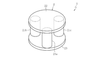
- FIG. 1 is a perspective view of the coupled inductor 1 according to the present embodiment
- FIG. 2 is a view of the coupled inductor 1 in a state where a later-described first joint 22 is removed, as viewed from the first joint 22 side.
- FIG. 1 As shown in FIGS. 1 and 2, the coupled inductor 1 has a core 2 and three windings 31a to 31c.
- the core 2 has legs 21a to 21c, and first and second joints 22 and 23 having the same shape and separated in the direction of the winding axis of the windings 31a to 31c.
- the first joint 22 joins one ends of the legs 21a to 21c
- the second joint 23 joins the other ends of the legs 21a to 21c.
- the leg portions 21a to 21c are formed in a columnar shape
- the first joint portion 22 and the second joint portion 23 are formed in a disk shape having the same diameter and the same thickness. Except for the three legs 21a to 21c, no other legs serving as magnetic flux paths are provided between the first joint 22 and the second joint 23.
- the leg portions 21a to 21c are arranged in a circumferential direction between the first joint portion 22 and the second joint portion 23 coaxially arranged on the center O such that the central angle ⁇ is 120 °. They are arranged in parallel to each other in an evenly distributed manner.
- FIG. 3 is a perspective view showing the shape of the core 2 when the windings 31a to 31c are removed from the coupled inductor 1 shown in FIG. As shown in FIG. 3, the core 2 is integrated such that both end surfaces of the legs 21a to 21c are in contact with the end surfaces of the first joint 22 and the second joint 23. The core 2 does not have an air gap.
- the legs 21a to 21c, the first joint 22 and the second joint 23 constituting the core 2 are all manufactured by compression molding soft magnetic powder and then performing annealing.
- the soft magnetic powder it is preferable to use a soft magnetic powder with an insulating coating obtained by coating an insulating coating made of a resin or the like on a soft magnetic metal powder of a pure iron type, an amorphous type, a soft magnetic alloy type, a nanocrystalline type or the like.
- the initial magnetic permeability (meaning the relative magnetic permeability at a magnetic field of 0 A / m) of the soft magnetic powder with the insulating coating is preferably 30 or more and 200 or less.
- the core 2 also has the same initial magnetic permeability as the magnetic powder before compression molding.
- the material of the core 2 it is preferable to use only the soft magnetic powder described above and not to use a mixed material obtained by mixing the soft magnetic powder and the resin powder.
- the leg portions 21a to 21c, the first joint portion 22, and the second joint portion 23 may be formed of the same material or different materials.
- winding 31a to 31c is attached to each leg 21a to 21c.
- Each of the windings 31a to 31c has the same number of turns, is formed of the same conductive material, and has the same cross-sectional dimension. Therefore, each of the windings 31a to 31c has the same inductance.
- the windings 31a to 31c are connected and arranged so as to have the same polarity. Specifically, as shown in FIG. 2, when a direct current (direction of an arrow in the drawing) flows in both windings 31a to 31c in the same direction, a magnetic flux (for example, FIG. 2, the windings 31a to 31c are connected to the circuit so as to generate a magnetic flux directed toward the front side in the vertical direction of FIG.
- the windings 31a to 31c wound in advance are attached to the outer periphery of each of the legs 21a to 21c. And then fix the second joint 23 to the other end of each of the legs 21a to 21c.
- Each of the legs 21a to 21c is fixed to the first joint 21 and the second joint by, for example, bonding.
- the coupling coefficient of the coupling inductor 1 be set in a range of 0.3 to 0.85 (preferably, 0.3 to 0.75).
- the use of the soft magnetic powder with the insulating coating as the material of the core 2 makes it easy to adjust the coupling coefficient, and it is possible to easily obtain a coupling coefficient within this range.
- the coupling coefficient here is obtained from the following equation based on the open / short method specified in JIS C 5321.
- Coupling coefficient k ⁇ 1-Lsc / Lop ⁇ 1/2
- Lsc is a short-circuit L value (all other lines are short-circuited)
- Lop is an open L value.
- FIG. 4 shows a schematic configuration of a DC-DC three-phase boost chopper circuit as an example of the switching circuit.
- each of the windings 31a to 31c of the coupled inductor 1 is connected to the power source E in parallel.
- the other end of the winding 31a is connected to the anode of the first diode D1 and one end of the first switching element Q1
- the other end of the winding 31b is connected to the anode of the second diode D2 and one end of the second switching element Q2. Is done.
- the other end of the winding 31c is connected to the anode of the third diode D3 and one end of the third switching element Q3.
- the other ends of the switching elements Q1 to Q3 are connected to the ground.
- Each of the switching elements Q1 to Q3 repeats the opening / closing operation at a constant cycle according to a control signal from a control device (not shown). At this time, the switching elements Q1 to Q3 repeat the opening / closing operation by shifting the phase by 120 °.
- the voltage and current output from the cathodes of the diodes D1 to D3 are smoothed by the smoothing capacitor C and consumed by the load R.
- the input current can be divided and the capacity can be further increased as compared with the case of two phases. Further, the capacity of the output-side smoothing capacitor can be further reduced.
- FIG. 5 is a plan view showing the flow of the magnetic flux at the first junction 22 in the coupled inductor 1 of the present embodiment. As shown in the figure, during the operation of the coupled inductor 1, DC magnetic fluxes (indicated by broken arrows) generated from the inductor average current cancel each other out.
- AC magnetic fluxes ⁇ ab , ⁇ ba , ⁇ bc , ⁇ cb , ⁇ ac , ⁇ ca can be shared by any combination of these to strengthen or cancel each other out to make a magnetic flux path. Circulate. As described above, the DC magnetic flux cancels each other, thereby reducing the magnetic flux in the core. On the other hand, a magnetic flux path through which the magnetic flux of the AC component circulates is formed, so that the inductance of the coupling inductor 1 increases. Therefore, the magnetic flux generated in the core 2 can be reduced, and the core 2 can be downsized. As a result, the ripple width can be reduced and the superimposition characteristics can be improved.
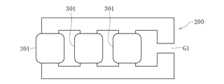
- the three-phase coupled inductor it is conceivable to use a four-leg type planar structure core 200 as shown in FIG. This is provided with three legs for winding the winding 301 and one leg having an air gap G1 for securing a path for leakage magnetic flux.
- this core structure the distance between the windings 301 and the magnetic path length of the path through which the leakage magnetic flux of each phase flows are different, and the symmetry is lacking. There is a difference. Therefore, there is a problem in that the performance of the coupled in inductor is deteriorated.
- a three-dimensional core structure shown in FIG. 11 can be considered (reference example).
- a core is provided with three outer legs 210 displaced from each other by 120 ° and a center leg 211 having an air gap G2, and a winding 310 is wound around each of the three outer legs 210.
- the center leg 211 is used as a path of the leakage magnetic flux.
- the magnetic flux does not cancel each other, and the magnetic flux flows into the central leg 211 (indicated by an arrow in the figure). Therefore, the diameter of the central leg 211 is increased due to the necessity of preventing magnetic saturation. I have to do it. Therefore, there is a limit in reducing the size of the coupling inductor.
- the core 2 is formed using soft magnetic powder with an insulating coating having an initial magnetic permeability of 30 to 200, ferrite (an initial magnetic permeability of 2300 to 2500) which is a general core material is used. Leakage magnetic flux is more likely to occur than in the case of using ()). Therefore, even if the central leg 211 shown in FIG. 11 is omitted, an appropriate leakage flux can be generated in the entire core 2. This makes it possible to reduce the size of the coupled inductor 1 while achieving the ripple suppressing effect and the improvement of the DC current superposition characteristics.
- FIGS. 6A to 6D are plan views of the coupled inductor 1 as viewed from the first joint portion 22 side.
- the embodiment shown in FIGS. 6A to 6D differs from the embodiment shown in FIGS. 1 and 2 in the core structure, but the other configurations are common.
- FIG. 6A shows an example in which the first joint portion 22 and the second joint portion 23 are formed in a perforated disk shape having a hole 24 at the center in the embodiment shown in FIG. 1, and FIG. An example in which the portion 22 and the second joining portion 23 are formed in a triangular plate shape is shown.
- FIG. 6C shows an example in which a hole 24 is provided at the center of the first joint portion 22 and the second joint portion 23 in the embodiment of FIG. 6B
- FIG. 6D shows that the first joint portion 22 and the second joint portion 23 are formed. This is an example in which it is formed in a shape extending radially from the center.
- FIGS. 6A to 6D the entire end surfaces of the three pillar portions 21a to 21c arranged at equal positions are covered by the first joint portion 22 and the second joint portion 23. .
- the coupled inductor 1 shown in FIG. 1 was used as an example.
- an inductor 1 ' was used in which the two windings 31b and 31c were removed from the coupled inductor of the first embodiment.
- the inductance value was measured from the current flowing when a voltage having a phase difference of 120 ° was applied to the three windings 31a, 31b, 31c.
- the inductance value when an alternating current was applied was measured.
- the core 2 in the example and the comparative example is formed of a soft magnetic powder with an insulating coating (initial magnetic permeability of 70) using an amorphous material as a soft magnetic material.
- V in and V out in both equations represent the input voltage and the output voltage in the inductors of the example and the comparative example. Further, d represents a duty ratio, ⁇ I represents a ripple current width, and f represents a switching frequency (50 kHz).
- the coupled inductor 1 is arranged in the boost chopper circuit has been described as an example.
- the coupled inductor 1 described above can be used in any circuit having an interleaved two-phase switching circuit.
- the present invention can be used for power transformation (for both step-down and step-up) in a PFC (power factor correction) circuit, a converter circuit, an inverter circuit, and the like, an inverter application, a converter application, and the like.
Landscapes
- Engineering & Computer Science (AREA)
- Power Engineering (AREA)
- Chemical & Material Sciences (AREA)
- Dispersion Chemistry (AREA)
- Dc-Dc Converters (AREA)
- Soft Magnetic Materials (AREA)
Abstract
L'invention concerne un inducteur couplé 1 qui est utilisé dans un circuit de commutation triphasé d'un système d'entrelacement et comprenant un noyau 2 et trois enroulements 31a à 31c couplés magnétiquement les uns aux autres. Le noyau 2 comprend : trois parties de jambe 21a à 21c qui sont enroulées avec des enroulements 31a à 31c, respectivement, et qui sont agencées et espacées de manière égale dans la direction circonférentielle ; une première partie de jonction 22 qui relie les extrémités respectives des parties de jambe ; et une seconde partie de jonction 23 qui relie les autres extrémités respectives des parties de jambe. Aucun espace d'air n'est ménagé dans le noyau 2.
Applications Claiming Priority (2)
| Application Number | Priority Date | Filing Date | Title |
|---|---|---|---|
| JP2018-149439 | 2018-08-08 | ||
| JP2018149439A JP2020025043A (ja) | 2018-08-08 | 2018-08-08 | 結合インダクタおよびスイッチング回路 |
Publications (1)
| Publication Number | Publication Date |
|---|---|
| WO2020031972A1 true WO2020031972A1 (fr) | 2020-02-13 |
Family
ID=69414707
Family Applications (1)
| Application Number | Title | Priority Date | Filing Date |
|---|---|---|---|
| PCT/JP2019/030760 Ceased WO2020031972A1 (fr) | 2018-08-08 | 2019-08-05 | Inducteur couplé et circuit de commutation |
Country Status (2)
| Country | Link |
|---|---|
| JP (1) | JP2020025043A (fr) |
| WO (1) | WO2020031972A1 (fr) |
Cited By (2)
| Publication number | Priority date | Publication date | Assignee | Title |
|---|---|---|---|---|
| CN116387000A (zh) * | 2023-02-24 | 2023-07-04 | 致瞻科技(上海)有限公司 | 一种电感及控制器 |
| US20230395316A1 (en) * | 2022-06-03 | 2023-12-07 | Honda Motor Co., Ltd. | Control device for power conversion device |
Families Citing this family (2)
| Publication number | Priority date | Publication date | Assignee | Title |
|---|---|---|---|---|
| JP7294303B2 (ja) * | 2020-10-29 | 2023-06-20 | 株式会社豊田中央研究所 | ノイズフィルタ |
| FR3132378A1 (fr) * | 2022-02-01 | 2023-08-04 | Valeo Siemens Eautomotive France Sas | Dispositif magnétique intégré |
Citations (3)
| Publication number | Priority date | Publication date | Assignee | Title |
|---|---|---|---|---|
| WO2011061984A1 (fr) * | 2009-11-18 | 2011-05-26 | 新東ホールディングス株式会社 | Dispositif de conversion de puissance |
| JP2014220435A (ja) * | 2013-05-09 | 2014-11-20 | 株式会社タムラ製作所 | リアクタ |
| JP2018022783A (ja) * | 2016-08-04 | 2018-02-08 | 田淵電機株式会社 | コイル装置 |
-
2018
- 2018-08-08 JP JP2018149439A patent/JP2020025043A/ja active Pending
-
2019
- 2019-08-05 WO PCT/JP2019/030760 patent/WO2020031972A1/fr not_active Ceased
Patent Citations (3)
| Publication number | Priority date | Publication date | Assignee | Title |
|---|---|---|---|---|
| WO2011061984A1 (fr) * | 2009-11-18 | 2011-05-26 | 新東ホールディングス株式会社 | Dispositif de conversion de puissance |
| JP2014220435A (ja) * | 2013-05-09 | 2014-11-20 | 株式会社タムラ製作所 | リアクタ |
| JP2018022783A (ja) * | 2016-08-04 | 2018-02-08 | 田淵電機株式会社 | コイル装置 |
Cited By (2)
| Publication number | Priority date | Publication date | Assignee | Title |
|---|---|---|---|---|
| US20230395316A1 (en) * | 2022-06-03 | 2023-12-07 | Honda Motor Co., Ltd. | Control device for power conversion device |
| CN116387000A (zh) * | 2023-02-24 | 2023-07-04 | 致瞻科技(上海)有限公司 | 一种电感及控制器 |
Also Published As
| Publication number | Publication date |
|---|---|
| JP2020025043A (ja) | 2020-02-13 |
Similar Documents
| Publication | Publication Date | Title |
|---|---|---|
| US10269484B2 (en) | Magnetic component and power conversion device using the same | |
| US10283261B2 (en) | Power conversion device | |
| CN108364761B (zh) | 集成磁性组件和切换模式功率转换器 | |
| US8339808B2 (en) | Switching power supply unit | |
| US9570535B2 (en) | Integrated magnetics component | |
| JP6098870B2 (ja) | リアクトル、コンバータ、及び電力変換装置 | |
| US8072785B2 (en) | Switching power supply unit | |
| US8031042B2 (en) | Power converter magnetic devices | |
| WO2020031972A1 (fr) | Inducteur couplé et circuit de commutation | |
| US9224531B2 (en) | Power converter using orthogonal secondary windings | |
| JP2017195684A (ja) | マルチフェーズ型コンバータ用リアクトル | |
| Jo et al. | Reconfigurable LLC resonant converter for bidirectional electric-vehicle chargers | |
| JP2019204945A (ja) | 結合インダクタおよびスイッチング回路 | |
| JP7142527B2 (ja) | 結合インダクタおよびスイッチング回路 | |
| Imaoka et al. | High-power-density three-phase interleaved boost converter with a novel coupled inductor | |
| Chiba et al. | Current balancing and phase shedding by split capacitor for a three-phase LLC resonant converter | |
| Imaoka et al. | Optimal design method for interleaved single-phase PFC converter with coupled inductor | |
| Mu et al. | Comparison and selection of magnetic materials for coupled inductor used in interleaved three-level multi-phase DC-DC converters | |
| Ebisumoto et al. | Design of a four-phase interleaved boost circuit with closed-coupled inductors | |
| Nakahama et al. | Trans-linked multi-phase boost converter for electric vehicle | |
| JP5715408B2 (ja) | 電源用チョークコイル | |
| Kimura et al. | Allowable power analysis for high power density DC-DC converters using integrated magnetic components | |
| Praneeth et al. | DC–DC converter with reduced circulating current in on-board battery chargers for electric transportation | |
| JP2017195726A (ja) | Dc−dcコンバータ | |
| WO2020054809A1 (fr) | Inducteur couplé et circuit de commutation |
Legal Events
| Date | Code | Title | Description |
|---|---|---|---|
| 121 | Ep: the epo has been informed by wipo that ep was designated in this application |
Ref document number: 19846175 Country of ref document: EP Kind code of ref document: A1 |
|
| NENP | Non-entry into the national phase |
Ref country code: DE |
|
| 122 | Ep: pct application non-entry in european phase |
Ref document number: 19846175 Country of ref document: EP Kind code of ref document: A1 |