WO2020032211A1 - Dispositif de génération de données, procédé de génération de données, programme de génération de données et système opérationnel à distance - Google Patents
Dispositif de génération de données, procédé de génération de données, programme de génération de données et système opérationnel à distance Download PDFInfo
- Publication number
- WO2020032211A1 WO2020032211A1 PCT/JP2019/031495 JP2019031495W WO2020032211A1 WO 2020032211 A1 WO2020032211 A1 WO 2020032211A1 JP 2019031495 W JP2019031495 W JP 2019031495W WO 2020032211 A1 WO2020032211 A1 WO 2020032211A1
- Authority
- WO
- WIPO (PCT)
- Prior art keywords
- robot
- real
- model
- peripheral object
- work space
- Prior art date
- Legal status (The legal status is an assumption and is not a legal conclusion. Google has not performed a legal analysis and makes no representation as to the accuracy of the status listed.)
- Ceased
Links
Images




Classifications
-
- G—PHYSICS
- G09—EDUCATION; CRYPTOGRAPHY; DISPLAY; ADVERTISING; SEALS
- G09B—EDUCATIONAL OR DEMONSTRATION APPLIANCES; APPLIANCES FOR TEACHING, OR COMMUNICATING WITH, THE BLIND, DEAF OR MUTE; MODELS; PLANETARIA; GLOBES; MAPS; DIAGRAMS
- G09B19/00—Teaching not covered by other main groups of this subclass
- G09B19/24—Use of tools
-
- G—PHYSICS
- G09—EDUCATION; CRYPTOGRAPHY; DISPLAY; ADVERTISING; SEALS
- G09B—EDUCATIONAL OR DEMONSTRATION APPLIANCES; APPLIANCES FOR TEACHING, OR COMMUNICATING WITH, THE BLIND, DEAF OR MUTE; MODELS; PLANETARIA; GLOBES; MAPS; DIAGRAMS
- G09B19/00—Teaching not covered by other main groups of this subclass
-
- A—HUMAN NECESSITIES
- A63—SPORTS; GAMES; AMUSEMENTS
- A63F—CARD, BOARD, OR ROULETTE GAMES; INDOOR GAMES USING SMALL MOVING PLAYING BODIES; VIDEO GAMES; GAMES NOT OTHERWISE PROVIDED FOR
- A63F13/00—Video games, i.e. games using an electronically generated display having two or more dimensions
- A63F13/25—Output arrangements for video game devices
-
- A—HUMAN NECESSITIES
- A63—SPORTS; GAMES; AMUSEMENTS
- A63F—CARD, BOARD, OR ROULETTE GAMES; INDOOR GAMES USING SMALL MOVING PLAYING BODIES; VIDEO GAMES; GAMES NOT OTHERWISE PROVIDED FOR
- A63F13/00—Video games, i.e. games using an electronically generated display having two or more dimensions
- A63F13/25—Output arrangements for video game devices
- A63F13/28—Output arrangements for video game devices responding to control signals received from the game device for affecting ambient conditions, e.g. for vibrating players' seats, activating scent dispensers or affecting temperature or light
-
- A—HUMAN NECESSITIES
- A63—SPORTS; GAMES; AMUSEMENTS
- A63F—CARD, BOARD, OR ROULETTE GAMES; INDOOR GAMES USING SMALL MOVING PLAYING BODIES; VIDEO GAMES; GAMES NOT OTHERWISE PROVIDED FOR
- A63F13/00—Video games, i.e. games using an electronically generated display having two or more dimensions
- A63F13/30—Interconnection arrangements between game servers and game devices; Interconnection arrangements between game devices; Interconnection arrangements between game servers
- A63F13/35—Details of game servers
-
- A—HUMAN NECESSITIES
- A63—SPORTS; GAMES; AMUSEMENTS
- A63F—CARD, BOARD, OR ROULETTE GAMES; INDOOR GAMES USING SMALL MOVING PLAYING BODIES; VIDEO GAMES; GAMES NOT OTHERWISE PROVIDED FOR
- A63F13/00—Video games, i.e. games using an electronically generated display having two or more dimensions
- A63F13/50—Controlling the output signals based on the game progress
-
- A—HUMAN NECESSITIES
- A63—SPORTS; GAMES; AMUSEMENTS
- A63F—CARD, BOARD, OR ROULETTE GAMES; INDOOR GAMES USING SMALL MOVING PLAYING BODIES; VIDEO GAMES; GAMES NOT OTHERWISE PROVIDED FOR
- A63F13/00—Video games, i.e. games using an electronically generated display having two or more dimensions
- A63F13/60—Generating or modifying game content before or while executing the game program, e.g. authoring tools specially adapted for game development or game-integrated level editor
- A63F13/65—Generating or modifying game content before or while executing the game program, e.g. authoring tools specially adapted for game development or game-integrated level editor automatically by game devices or servers from real world data, e.g. measurement in live racing competition
-
- A—HUMAN NECESSITIES
- A63—SPORTS; GAMES; AMUSEMENTS
- A63F—CARD, BOARD, OR ROULETTE GAMES; INDOOR GAMES USING SMALL MOVING PLAYING BODIES; VIDEO GAMES; GAMES NOT OTHERWISE PROVIDED FOR
- A63F13/00—Video games, i.e. games using an electronically generated display having two or more dimensions
- A63F13/60—Generating or modifying game content before or while executing the game program, e.g. authoring tools specially adapted for game development or game-integrated level editor
- A63F13/67—Generating or modifying game content before or while executing the game program, e.g. authoring tools specially adapted for game development or game-integrated level editor adaptively or by learning from player actions, e.g. skill level adjustment or by storing successful combat sequences for re-use
-
- A—HUMAN NECESSITIES
- A63—SPORTS; GAMES; AMUSEMENTS
- A63F—CARD, BOARD, OR ROULETTE GAMES; INDOOR GAMES USING SMALL MOVING PLAYING BODIES; VIDEO GAMES; GAMES NOT OTHERWISE PROVIDED FOR
- A63F13/00—Video games, i.e. games using an electronically generated display having two or more dimensions
- A63F13/90—Constructional details or arrangements of video game devices not provided for in groups A63F13/20 or A63F13/25, e.g. housing, wiring, connections or cabinets
-
- B—PERFORMING OPERATIONS; TRANSPORTING
- B25—HAND TOOLS; PORTABLE POWER-DRIVEN TOOLS; MANIPULATORS
- B25J—MANIPULATORS; CHAMBERS PROVIDED WITH MANIPULATION DEVICES
- B25J13/00—Controls for manipulators
- B25J13/006—Controls for manipulators by means of a wireless system for controlling one or several manipulators
-
- B—PERFORMING OPERATIONS; TRANSPORTING
- B25—HAND TOOLS; PORTABLE POWER-DRIVEN TOOLS; MANIPULATORS
- B25J—MANIPULATORS; CHAMBERS PROVIDED WITH MANIPULATION DEVICES
- B25J13/00—Controls for manipulators
- B25J13/02—Hand grip control means
-
- B—PERFORMING OPERATIONS; TRANSPORTING
- B25—HAND TOOLS; PORTABLE POWER-DRIVEN TOOLS; MANIPULATORS
- B25J—MANIPULATORS; CHAMBERS PROVIDED WITH MANIPULATION DEVICES
- B25J13/00—Controls for manipulators
- B25J13/06—Control stands, e.g. consoles, switchboards
-
- B—PERFORMING OPERATIONS; TRANSPORTING
- B25—HAND TOOLS; PORTABLE POWER-DRIVEN TOOLS; MANIPULATORS
- B25J—MANIPULATORS; CHAMBERS PROVIDED WITH MANIPULATION DEVICES
- B25J13/00—Controls for manipulators
- B25J13/06—Control stands, e.g. consoles, switchboards
- B25J13/065—Control stands, e.g. consoles, switchboards comprising joy-sticks
-
- B—PERFORMING OPERATIONS; TRANSPORTING
- B25—HAND TOOLS; PORTABLE POWER-DRIVEN TOOLS; MANIPULATORS
- B25J—MANIPULATORS; CHAMBERS PROVIDED WITH MANIPULATION DEVICES
- B25J13/00—Controls for manipulators
- B25J13/08—Controls for manipulators by means of sensing devices, e.g. viewing or touching devices
- B25J13/081—Touching devices, e.g. pressure-sensitive
- B25J13/082—Grasping-force detectors
-
- B—PERFORMING OPERATIONS; TRANSPORTING
- B25—HAND TOOLS; PORTABLE POWER-DRIVEN TOOLS; MANIPULATORS
- B25J—MANIPULATORS; CHAMBERS PROVIDED WITH MANIPULATION DEVICES
- B25J13/00—Controls for manipulators
- B25J13/08—Controls for manipulators by means of sensing devices, e.g. viewing or touching devices
- B25J13/088—Controls for manipulators by means of sensing devices, e.g. viewing or touching devices with position, velocity or acceleration sensors
-
- B—PERFORMING OPERATIONS; TRANSPORTING
- B25—HAND TOOLS; PORTABLE POWER-DRIVEN TOOLS; MANIPULATORS
- B25J—MANIPULATORS; CHAMBERS PROVIDED WITH MANIPULATION DEVICES
- B25J19/00—Accessories fitted to manipulators, e.g. for monitoring, for viewing; Safety devices combined with or specially adapted for use in connection with manipulators
-
- B—PERFORMING OPERATIONS; TRANSPORTING
- B25—HAND TOOLS; PORTABLE POWER-DRIVEN TOOLS; MANIPULATORS
- B25J—MANIPULATORS; CHAMBERS PROVIDED WITH MANIPULATION DEVICES
- B25J19/00—Accessories fitted to manipulators, e.g. for monitoring, for viewing; Safety devices combined with or specially adapted for use in connection with manipulators
- B25J19/02—Sensing devices
- B25J19/021—Optical sensing devices
-
- B—PERFORMING OPERATIONS; TRANSPORTING
- B25—HAND TOOLS; PORTABLE POWER-DRIVEN TOOLS; MANIPULATORS
- B25J—MANIPULATORS; CHAMBERS PROVIDED WITH MANIPULATION DEVICES
- B25J3/00—Manipulators of leader-follower type, i.e. both controlling unit and controlled unit perform corresponding spatial movements
-
- B—PERFORMING OPERATIONS; TRANSPORTING
- B25—HAND TOOLS; PORTABLE POWER-DRIVEN TOOLS; MANIPULATORS
- B25J—MANIPULATORS; CHAMBERS PROVIDED WITH MANIPULATION DEVICES
- B25J9/00—Program-controlled manipulators
- B25J9/0081—Program-controlled manipulators with leader teach-in means
-
- B—PERFORMING OPERATIONS; TRANSPORTING
- B25—HAND TOOLS; PORTABLE POWER-DRIVEN TOOLS; MANIPULATORS
- B25J—MANIPULATORS; CHAMBERS PROVIDED WITH MANIPULATION DEVICES
- B25J9/00—Program-controlled manipulators
- B25J9/16—Program controls
- B25J9/1602—Program controls characterised by the control system, structure, architecture
- B25J9/1605—Simulation of manipulator lay-out, design, modelling of manipulator
-
- B—PERFORMING OPERATIONS; TRANSPORTING
- B25—HAND TOOLS; PORTABLE POWER-DRIVEN TOOLS; MANIPULATORS
- B25J—MANIPULATORS; CHAMBERS PROVIDED WITH MANIPULATION DEVICES
- B25J9/00—Program-controlled manipulators
- B25J9/16—Program controls
- B25J9/1602—Program controls characterised by the control system, structure, architecture
- B25J9/161—Hardware, e.g. neural networks, fuzzy logic, interfaces, processor
-
- B—PERFORMING OPERATIONS; TRANSPORTING
- B25—HAND TOOLS; PORTABLE POWER-DRIVEN TOOLS; MANIPULATORS
- B25J—MANIPULATORS; CHAMBERS PROVIDED WITH MANIPULATION DEVICES
- B25J9/00—Program-controlled manipulators
- B25J9/16—Program controls
- B25J9/1628—Program controls characterised by the control loop
- B25J9/163—Program controls characterised by the control loop learning, adaptive, model based, rule based expert control
-
- B—PERFORMING OPERATIONS; TRANSPORTING
- B25—HAND TOOLS; PORTABLE POWER-DRIVEN TOOLS; MANIPULATORS
- B25J—MANIPULATORS; CHAMBERS PROVIDED WITH MANIPULATION DEVICES
- B25J9/00—Program-controlled manipulators
- B25J9/16—Program controls
- B25J9/1656—Program controls characterised by programming, planning systems for manipulators
- B25J9/1661—Program controls characterised by programming, planning systems for manipulators characterised by task planning, object-oriented languages
-
- B—PERFORMING OPERATIONS; TRANSPORTING
- B25—HAND TOOLS; PORTABLE POWER-DRIVEN TOOLS; MANIPULATORS
- B25J—MANIPULATORS; CHAMBERS PROVIDED WITH MANIPULATION DEVICES
- B25J9/00—Program-controlled manipulators
- B25J9/16—Program controls
- B25J9/1656—Program controls characterised by programming, planning systems for manipulators
- B25J9/1671—Program controls characterised by programming, planning systems for manipulators characterised by simulation, either to verify existing program or to create and verify new program, CAD/CAM oriented, graphic oriented programming systems
-
- B—PERFORMING OPERATIONS; TRANSPORTING
- B25—HAND TOOLS; PORTABLE POWER-DRIVEN TOOLS; MANIPULATORS
- B25J—MANIPULATORS; CHAMBERS PROVIDED WITH MANIPULATION DEVICES
- B25J9/00—Program-controlled manipulators
- B25J9/16—Program controls
- B25J9/1694—Program controls characterised by use of sensors other than normal servo-feedback from position, speed or acceleration sensors, perception control, multi-sensor controlled systems, sensor fusion
- B25J9/1697—Vision controlled systems
-
- G—PHYSICS
- G09—EDUCATION; CRYPTOGRAPHY; DISPLAY; ADVERTISING; SEALS
- G09B—EDUCATIONAL OR DEMONSTRATION APPLIANCES; APPLIANCES FOR TEACHING, OR COMMUNICATING WITH, THE BLIND, DEAF OR MUTE; MODELS; PLANETARIA; GLOBES; MAPS; DIAGRAMS
- G09B19/00—Teaching not covered by other main groups of this subclass
- G09B19/16—Control of vehicles or other craft
-
- G—PHYSICS
- G09—EDUCATION; CRYPTOGRAPHY; DISPLAY; ADVERTISING; SEALS
- G09B—EDUCATIONAL OR DEMONSTRATION APPLIANCES; APPLIANCES FOR TEACHING, OR COMMUNICATING WITH, THE BLIND, DEAF OR MUTE; MODELS; PLANETARIA; GLOBES; MAPS; DIAGRAMS
- G09B5/00—Electrically-operated educational appliances
- G09B5/02—Electrically-operated educational appliances with visual presentation of the material to be studied, e.g. using film strip
-
- G—PHYSICS
- G09—EDUCATION; CRYPTOGRAPHY; DISPLAY; ADVERTISING; SEALS
- G09B—EDUCATIONAL OR DEMONSTRATION APPLIANCES; APPLIANCES FOR TEACHING, OR COMMUNICATING WITH, THE BLIND, DEAF OR MUTE; MODELS; PLANETARIA; GLOBES; MAPS; DIAGRAMS
- G09B9/00—Simulators for teaching or training purposes
Definitions
- the present invention relates to a data generation device, a data generation method, a data generation program, and a remote operation system in a system in which an operator remotely controls a remote robot through a network.
- Patent Literature 1 discloses a remote operation system that can grasp a communication delay between a slave device and a master device.
- the remote control system disclosed in Patent Document 1 includes a master device and a slave device.
- the slave device includes a slave robot that operates according to operation information corresponding to an operator's operation sent from the master device.
- the slave robot has an imaging device that images its own work environment, and the slave device sequentially shoots the work environment and transmits the photographed real image to the master device.
- the master device includes a simulator that performs an operation simulation based on operation information sent to the slave robot, and combines a real image sent from the slave device with a simulation image obtained by the operation simulation to display a display image. Generate. The ratio of the synthesis of the real image and the simulation image in the display image is changed according to the communication delay between the master device and the slave device.
- the ratio of the simulation image is increased to generate the display image.
- the actual image is an image that reflects the background of the work environment as well as the status of the slave robot
- the simulation image is an image that displays only the status of the slave robot. For this reason, it is possible for the operator to easily grasp the degree of the communication delay from the display image, for example, whether the background of the work environment appears dark.
- the present invention provides a data generation device, a data generation method, a data generation program, and a remote operation system that can suppress the influence of a communication delay between an operation terminal operated by an operator and a robot on the operation of the operator.
- the purpose is to provide.
- a data generation device includes an operation terminal having an operation device that receives an operation of an operator and a display device that can be visually recognized by the operator;
- a remote operation system including a real robot installed and connected via a network capable of data communication with the operation terminal, wherein at least a part of data used for generation of an image displayed on the display is generated.
- a working space model obtained by modeling the real working space as a moving image (time-varying image) on the display, and the working space model displays the real robot.
- the data generation device is created to operate in response to the operation of the operator, the data generating device acquires a state information acquisition unit that acquires state information indicating the state of the real surroundings, and a predetermined time from the current time based on the state information
- a prediction unit that predicts a state of the real peripheral object after a minute, and generates a predicted result as peripheral object model data used for creating the peripheral object model displayed on the display device.
- the robot model operates at the same time due to the time lag between when the operator operates the operating device and when the real robot performs the operation corresponding to the operation. And the operation of the real robot may be shifted.
- the prediction unit predicts the state of the real peripheral object a predetermined time later than the current time, and the prediction result is used as peripheral object model data used for creating a peripheral object model displayed on the display. Generated. Therefore, the same time lag between the state of the peripheral object model and the state of the real peripheral object as that between the robot model and the real robot can be generated. Thereby, the time axis of the robot model and the time axis of the peripheral object model can be made to coincide with each other, so that the influence of the communication delay on the operation of the operator can be suppressed.
- the real peripheral object may include at least one of a work to be worked by the real robot, a transfer device for transferring the work, and a moving device for moving the real robot.
- the state information may include imaging information generated by an imaging device installed in the work space imaging the real surroundings.
- the state information may include setting information set in a peripheral device as the real peripheral object.
- a deviation detecting unit for detecting the degree may be further provided. For example, when the displacement detected by the displacement detection unit is larger than a predetermined value, it is possible to take measures such as stopping the operation of the actual robot or correcting the model displayed on the display.
- the data generation device further includes a model correction unit that corrects the work space model so that the deviation is eliminated when the deviation detected by the deviation detecting unit exceeds a preset range. Is also good.
- the operation terminal may be a game device including a controller as the operation device.
- the operation terminal may be at least one of a personal information terminal (PDA (Personal Data Assistant)), a smartphone, a personal computer, a tablet, and a remote controller dedicated to a robot.
- PDA Personal Information terminal
- a data generation method includes an operation device having an operation device that accepts an operation of an operator and a display device that can be visually recognized by the operator; and an operation terminal installed in a work space;
- a remote operation system including a real robot connected via a communicable network, a data generating method for generating at least a part of data used for generating an image displayed on the display.
- a work space model that models the real work space is displayed as a moving image on the display, and the work space model is located around the real robot and a robot model that models the real robot.
- a peripheral object model obtained by modeling a peripheral object, wherein the robot model is created so as to operate in accordance with the operation of the operator on the operation device.
- the data generation method includes: a state information obtaining step of obtaining state information indicating a state of a peripheral object around the real robot; and predicting a state of the peripheral object after the present time based on the state information.
- a data generation program includes an operation device having an operation device that receives an operation of an operator and a display device that can be visually recognized by the operator; And a real robot connected via a communicable network, wherein at least a part of data used for generating an image displayed on the display is generated by being executed by a computer.
- a data generation program wherein the display device displays, as a moving image, a work space model that models the real work space, wherein the work space model includes a robot model that models the real robot, A peripheral object model that models a peripheral object around the real robot, wherein the robot model is
- the data generation program is generated by an operation of the operator, and the data generation program obtains state information indicating a state of a peripheral object around the real robot, and based on the state information, A prediction step of predicting a state of the peripheral object and generating a result of the prediction as peripheral object model data used for creating the peripheral object model displayed on the display device.
- the data generation program is stored in a storage device.
- the storage device is a readable / writable or readable device built in or external to the computer, and may be, for example, a hard disk, a flash memory, an optical disk, or the like.
- the program stored in the storage device may be executed on a computer to which the storage device is directly connected, or may be downloaded and executed on a computer connected to the storage device via a network (for example, the Internet). You may.
- the remote operation system is an operation terminal having an operation device that receives an operation of an operator and a display device that can be visually recognized by the operator, and is installed in an actual work space, and the operation terminal A real robot connected via a network capable of data communication, wherein the display device displays a working space model obtained by modeling the real working space as a moving image,
- the space model includes a robot model that models the real robot and a peripheral object model that models a real peripheral object around the real robot, wherein the robot model is operated by the operator with respect to the operating device.
- the remote operation system is configured to operate in accordance with the state information acquisition unit that acquires state information indicating the state of the real surroundings; And predicting the state of the real peripheral object a predetermined time later than the current time, and generating the predicted result as peripheral object model data used for creating the peripheral object model displayed on the display. And a data generation device including a prediction unit that performs the calculation.
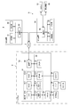
- FIG. 2 is a block diagram illustrating an example of a hardware configuration of a game device, a relay device, and an intermediary device in FIG. 1.
- FIG. 2 is a diagram schematically illustrating an example of the robot system in FIG. 1.
- FIG. 2 is a block diagram illustrating a functional configuration of a control unit of the game device in FIG. 1.
- FIG. 2 is a block diagram illustrating a functional configuration of a control unit of the relay device of FIG. 1.
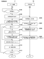
- FIG. 4 is a diagram showing a processing flow before starting work of a robot in each of the game device and the relay device. It is a figure showing the processing flow after the start of work of the robot in each of the game device and the relay device. It is a figure for explaining an example of processing performed as time passes in each of a game device and a relay device.
- FIG. 1 is a block diagram showing the overall configuration of the remote operation system 1.
- the remote operation system 1 of the present embodiment includes a well-known various game device 2 (operation terminal) and a remote work site (work space; hereinafter, also referred to as an “actual work space”) different from the place where the operator is located. Is connected via the communication network 4 to the robot 51 installed in the robot. Then, the operator remotely controls the robot 51 using the game device 2 to cause the robot 51 to perform a predetermined operation.
- the remote control system 1 includes a plurality of game apparatuses 2, one intermediary apparatus 6, and a plurality of robot systems 5, which can communicate with each other via a communication network 4 such as the Internet.
- the game device 2 is, for example, a stationary game device placed at the home of the operator or a portable game device carried by the operator.
- the robot system 5 includes a robot 51 to be remotely controlled by an operator, one or more peripheral devices 52 installed around the robot 51, and a relay device 53.
- the robot 51, the peripheral device 52, and the relay device 53 are all installed at a remote work site remote from a place where an operator operating the game apparatus 2 is located. At the work site, one or more robot systems 5 exist.
- the plurality of robot systems 5 included in the remote control system 1 may be installed at the same work site or at different work sites. Also, a plurality of robot systems 5 installed at the same work site may have peripheral devices 52 shared by each other. Note that the plurality of robot systems 5 may include a plurality of peripheral devices 52 of the same type or different types. However, in FIG. 1, for simplification of the drawing, a block indicating the peripheral devices 52 is one for each robot system 5. Only one is shown.
- the relay device 53 is communicably connected to each of the robot 51 and the peripheral device 52 of the same robot system 5 including the relay device 53.
- the relay device 53 sends information transmitted from the game device 2 or the mediation device 6 to the robot 51 or the peripheral device 52 via the communication network 4 or transmits information of the robot 51 or the peripheral device 52 to the game device 2 or the mediation device 6. Or send it to
- the mediation device 6 assigns one robot system 5 to one operator (one game device 2). More specifically, the operator accesses the intermediary device 6 from the game device 2 and registers the user in advance, and the user ID is given to the operator by the user registration. When the operator inputs his / her user ID in the game device 2 and sends an operation request to the mediation device 6, the mediation device 6 that has received the operation request associates the game device 2 with one of the robot systems 5, The game device 2 is connected to the relay device 53 of the robot system 5 associated with the game device 2 via the communication network 4.
- the intermediary device 6 upon receiving an operation request from the game device 2, the intermediary device 6 sends to the game device 2 work list information indicating the content of the work or the like.
- the operation request includes desired condition information input by the operator.
- the desired condition information includes the type of the robot, the work content of the robot, the target work, the work amount, and part or all of the work time.
- the intermediary device 6 filters, based on the desired condition information included in the operation request, those that meet the conditions desired by the operator, and sends the filtered work list to the game device 2.
- designation information corresponding to the designation of the operator is transmitted from the game device 2 to the intermediary device 6. .
- the mediation device 6 connects the game device 2 to the relay device 53 of the robot system 5 corresponding to the designated information.
- the operator can remotely control the robots 51 at various work sites physically far apart using the game apparatus 2.
- the remote control system 1 allows the operator to operate the robot 51 at the work site on the back side of the earth while staying at home.
- a communication environment of each of the game device 2 and the robot system 5 and a physical distance between the game device 2 and the robot system 5 are set.
- a communication delay due to the above may occur.
- the remote operation system 1 that suppresses the influence of a communication delay occurring between the game device 2 and the robot 51 connected to each other on the operation of the operator is realized.
- FIG. 2 illustrates an example of a hardware configuration of the game device 2, the relay device 53, and the mediation device 6.
- the game device 2 includes a game device body 2a, a display device 25 (display), a speaker 27, and a controller 28 (operator) connected thereto.
- the game apparatus main body 2a includes a control unit 21, a communication unit 22, and a storage unit 23 such as a hard disk or a memory card on a bus 20.
- the control unit 21 generates operation information to be sent to the robot 51 via the communication network 4 based on the operation of the controller 28.
- the robot 51 operates based on this operation information.
- the control unit 21 generates an image displayed on the display device 25 based on an operation of the controller 28.
- the control unit 21 includes a CPU 210, a ROM (flash memory) 211, a RAM 212, an image processor 213, an audio processor 214, and an operation unit 215.
- the CPU 210 controls the operation of each unit of the game device 2.
- the ROM 211 stores a basic program of the game apparatus 2 and the like.
- the storage unit 23 stores a remote operation program for operating the robot 51 by remote operation, a game program for executing various games, and the like.
- the RAM 212 a work area used when the CPU 210 executes the game program is set.
- the storage of the remote control program in the storage unit 23 is essential, but the storage of the game program is not essential.
- the ROM 211, the RAM 212, the storage unit 23, and the like of the control unit 21 in which various programs and data are stored are collectively referred to as a storage device of the game device 2.
- the image processor 213 includes a GPU (Graphics Processing Unit) capable of generating a game screen.
- a video RAM (VRAM) 24 is connected to the image processor 213.
- a display device 25 is connected to the VRAM 24.
- the audio processor 214 includes a DSP (Digital Signal Processor) that generates game audio.
- the sound processor 214 transmits the generated game sound to the amplifier 26 including the D / A converter.
- the amplifier 26 amplifies this audio signal and transmits it to the speaker 27.
- the controller 28 is connected to the operation unit 215 by wireless or wired communication.
- the controller 28 includes a cross button, a push switch, a joystick, a mouse, a keyboard, a touch panel, and the like. Further, the operation unit 215 detects an operation signal from the user via the controller 28, and transmits the operation signal to the CPU 210.
- the communication unit 22 is a communication device that communicates with the mediation device 6 and the relay device 53 via the communication network 4.
- the mediation device 6 includes a control unit 61, a communication unit 62, and a storage unit 63.
- the control unit 61 is configured by, for example, an arithmetic unit having a processor and a memory. Specifically, the arithmetic unit is configured by, for example, a microcontroller, an MPU, an FPGA (Field Programmable Gate Array), a PLC (Programmable Logic Controller), a computer, a personal computer, and the like.
- the control unit 61 may be configured by a single arithmetic unit that performs centralized control, or may be configured by a plurality of arithmetic units that perform distributed control.
- the communication unit 62 is a communication device that communicates with the game device 2 and the relay device 53 via the communication network 4.
- the storage unit 63 is a readable / writable or readable storage device, and is, for example, a hard disk, a flash memory, an optical disk, or the like.
- the control unit 61 controls the operation of each unit of the mediation device 6.
- Various programs and data for controlling the operation of the mediation device 6, such as a program for associating the game device 2 with the robot system 5, are stored in the memory and the storage unit 63 of the control unit 61.
- the relay device 53 includes a control unit 55, a communication unit 56, and a storage unit 57.
- the control unit 55 is configured by, for example, an arithmetic unit having a processor and a memory. Specifically, the arithmetic unit is configured by, for example, a microcontroller, an MPU, an FPGA (Field Programmable Gate Array), a PLC (Programmable Logic Controller), a computer, a personal computer, and the like.
- the control unit 55 may be configured by a single arithmetic unit that performs centralized control, or may be configured by a plurality of arithmetic units that perform distributed control.
- the communication unit 56 is a communication device that communicates with the game device 2, the mediation device 6, the robot 51, and the peripheral device 52 via the communication network 4.
- the storage unit 57 is a readable / writable or readable storage device, and is, for example, a hard disk, a flash memory, an optical disk, or the like.
- the control unit 55 controls the operation of the relay device 53. Various programs and data for controlling the operation of the relay device 53 are stored in the memory and the storage unit 57 of the control unit 55.
- FIG. 3 schematically shows an example of the robot system 5.
- the robot 51 performs an operation of picking the work W conveyed by the conveyor 52a.
- the robot 51 is an industrial robot.
- the robot 51 includes a robot main body 51a to be remotely operated by an operator, and a robot controller 51b for controlling the operation of the robot main body 51a.
- the robot main body 51a shown in FIG. 3 is a vertical articulated robot arm having a tool attached to the distal end.
- a workpiece W is attached to the distal end of the vertical articulated robot arm as a tool.
- a gripping hand capable of gripping is mounted.
- the robot controller 51b includes a processor.
- the processor performs decoding, arithmetic processing, and the like of stored programs and various signals input from the outside, and controls the operation of the robot body 51a and outputs signals from various output ports. Take control.
- the robot system 5 of FIG. 3 includes, as the peripheral devices 52, a conveyor 52a for transporting a work to be worked, one or more (two in this example) imaging devices 52b for shooting the work situation of the robot 51, and a work.
- a sensor 52c for detecting the position of W is provided.
- the configuration of the robot system 5 shown in FIG. 3 is an example, and the types of the robot 51 and the peripheral devices 52 are configured according to the work of the robot 51.
- the operation of the robot 51 may be, for example, a painting operation, a lunch box arrangement operation, a welding operation, or the like, in addition to the picking operation.
- the robot 51 need not be a vertical articulated robot, but may be an industrial robot such as a horizontal articulated robot, a parallel link robot, a polar coordinate robot, a cylindrical coordinate robot, or a rectangular coordinate robot.
- the transfer device as the peripheral device 52 for transferring the work W to be worked may be a transfer device other than the conveyor.
- the peripheral device 52 may include a moving device that moves the robot body 51a.
- the one or more sensors as the peripheral device 52 may be, for example, a sensor that detects the position or posture of the robot 51 instead of or in addition to the sensor that detects the position of the work W.
- the one or more sensors as the peripheral device 52 include a sensor that detects the position, orientation, or orientation of the inspection target.
- the robot system 5 may include a plurality of imaging devices 52b as the peripheral devices 52. As shown in FIG. 3, the imaging device 52b may be attached to the robot main body 51a, or may be provided at a fixed position in the work space.
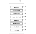
- FIG. 4 is a block diagram showing a functional configuration of the control unit 21 of the game device 2.
- the control unit 21 of the game device 2 includes, as functional components, a communication control unit 31, an operation-side time management unit 32, a state information acquisition unit 33, a simulation unit (prediction unit) 34, an image display unit 35, a communication delay measurement unit. 36, a deviation detecting unit 37, and a model correcting unit 38.
- These functional units are functionally realized in cooperation with a predetermined program stored in the storage device of the game device 2.
- the predetermined program stored in the storage device of the game device 2 includes the “data generation program” of the present invention.
- the communication control unit 31 controls the communication unit 22 to send the above-described operation request and designation information to the mediation device 6, and receive list information from the mediation device 6.
- the communication control unit 31 controls the communication unit 22 to receive information from the mediation device 6 for the mediation device 6 to make a communication connection with the robot system 5 associated with the game device 2.
- the communication control unit 31 controls the communication unit 22 to send operation information generated by the operator operating the controller 28 to the corresponding relay device 53 of the robot system 5.
- the operation-side time management unit 32 manages the time on the game device 2 side so that the time from when the operator operates the controller 28 to when the robot 51 operates based on the operation is kept constant. I do.
- the state information acquisition unit 33 and the simulation unit 34 generate at least a part of data used for generating an image displayed on the display device 25.
- the display device 25 displays, as a moving image, a work space model obtained by modeling a work space (hereinafter, “actual work space”) in which a robot (hereinafter, “actual robot”) 51 actually exists.
- the work space model includes a robot model and a peripheral object model arranged in a virtual work space.
- the robot model is a model of the real robot 51.
- the peripheral object model is a model of a predetermined peripheral object around the real robot 51 (hereinafter, “real peripheral object”).
- the actual peripheral object includes a peripheral device 52 and a work W located around the robot 51, and the peripheral object model includes a corresponding peripheral device model and a work model.
- robot model data and peripheral object model data are used for generating an image displayed on the display device 25.
- the robot model data includes static information of the real robot 51.
- the static information of the robot model includes, for example, structural information indicating the structure of the real robot 51 (the number of joints and the link length of the robot main body 51a, the structure of the tool, and the like) and information indicating the position and / or posture before starting the work. (For example, rotation angle information of a servo motor included in the robot body 51a).
- the robot model data includes dynamic information of the robot model, that is, operation information (command) of the operator on the controller 28. This operation information is used for operating the robot model, and is also transmitted from the game device 2 to the real robot 51 via the communication network 4 and used for the operation of the real robot 51.
- the real robot 51 at the work site also operates.
- the real robot 51 operates with a certain time delay from the operation of the robot model.
- the peripheral object model data includes static information of the actual peripheral object.
- the static information of the real peripheral object includes structural information of the peripheral device 52, information indicating the position and / or posture of the peripheral device 52 before the start of work, shape data and structure information of the work W to be worked by the real robot 51. , Information indicating the position and / or posture of the work W before the start of the work.
- the peripheral object model data includes information that predicts the position and orientation of the actual peripheral object a predetermined time ahead. This prediction is performed by the state information acquisition unit 33 and the simulation unit 34.
- the game device 2 including the state information acquisition unit 33 and the simulation unit 34 corresponds to the “data generation device” of the present invention.
- the state information obtaining unit 33 obtains state information indicating the state of a peripheral device 52 around the real robot 51 or the state of a real peripheral object such as a work W. Then, the simulating unit 34 simulates a change in the position or orientation of the real peripheral object over time based on the state information. For example, the state information acquisition unit 33 outputs, at a certain point, information indicating a transfer speed set in a transfer device (in this example, a conveyor 51a) as the peripheral device 52 and information indicating a position of the work W transferred to the transfer device. Is obtained as the state information, the simulation unit 34 can easily calculate the position and orientation of the work W a predetermined time ahead from the transport speed information and the work position information. As described above, the simulation unit 34 predicts the state of the real peripheral object a predetermined time later than the current time by the simulation. Then, the simulation unit 34 generates the predicted result as peripheral object model data used for creating a peripheral object model.
- a transfer speed set in a transfer device in this example, a
- the image display unit 35 displays the work space model created based on the robot model data and the peripheral object model data on the display device 25.
- the image display unit 35 arranges a virtual camera in a virtual work space in which a robot model and a peripheral object model created based on the robot model data and the peripheral object model data are arranged.
- the image captured by the virtual camera is displayed on the display device 25.
- the position, orientation, zoom, and the like of the virtual camera may be determined in advance, or may be changeable according to, for example, an operation performed on the controller 28 by an operator.
- the position and orientation of the virtual camera in the virtual work space may correspond to the position and orientation of the imaging device 52b in the real work space, respectively.
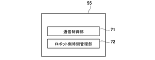
- FIG. 5 is a block diagram showing a functional configuration of the control unit 55 of the relay device 53.
- the control unit 55 of the relay device 53 has a communication control unit 71 and a robot-side time management unit 72 as a functional configuration. These functional units are functionally realized in cooperation with a predetermined program stored in the control unit 55 and / or the storage unit 57 of the relay device 53.
- the communication control unit 71 controls the communication unit 56 to receive, from the game device 2, operation information generated by the operator operating the controller 28.
- the robot-side time management unit 72 manages the time on the robot system 5 side so that the time from when the operator operates the controller 28 to when the robot 51 operates based on the operation is kept constant. I do.
- FIG. 6 is a diagram showing a processing flow before starting work of the robot 51 in each of the game apparatus 2 and the relay apparatus 53.
- the robot model, the peripheral device model, and the work model in the work space model are created so as to be in the same state as the real robot 51, the peripheral device 52, and the work W, respectively.
- the communication control unit 71 of the relay apparatus 53 transmits information for creating a work space model before the start of work to the game apparatus. 2 (step S201).
- the information for creating the work space model before the start of the work includes state information indicating the state of the real surroundings around the real robot 51.
- the state information includes imaging information generated by imaging the peripheral device 52 and the work W by the imaging device 52b installed in the actual work space. Further, the state information includes detection information of a sensor as the peripheral device 52.
- the detection information of the sensor includes, for example, information indicating whether the work W is at a predetermined position in the work space, information indicating the position or posture of the work W, and the like.
- the state information includes setting information set in the peripheral device 52. For example, when the robot system 5 includes a transfer device as the peripheral device 52, the setting information may include a transfer speed and a transfer interval set for the transfer device.
- the transport interval may be the distance between the workpieces W to be transported, or from the time when a certain workpiece W is transported to a predetermined position in front of the robot 51, the next workpiece W is transported to a predetermined location. May be a time interval until the time.
- the status information sent from the relay device 53 to the game device 2 includes information indicating the status of the real robot 51.
- the information indicating the state of the real robot 51 may include, for example, posture information and position information of the real robot 51 stored in the robot controller 51b.
- the information indicating the state of the real robot 51 may include imaging information obtained by the imaging device 52b, which is the peripheral device 52, and detection information of the sensor 52c.
- the status information acquisition unit 33 acquires the status information received from the relay device 53 (Step S101). Then, the simulation unit 34 creates a work space model having the same state as the actual work space before the start of the work, based on the state information acquired by the state information acquisition unit 33 (step S102).
- the state information includes, for example, shape data and structure information of the work W, the position and orientation of the work W, position information and structure information of the peripheral device 52, setting information, and the like.
- the simulating unit 34 determines the position information (position coordinates in the coordinate system set for the actual work space) and the posture information (the rotation angle of the servo motor of the robot body 51a) before the start of the work. Information, etc.), a robot model is created such that the state (position, posture, etc.) of the robot model is the same as that of the real robot 51. Further, the simulating unit 34 creates a peripheral object model based on the state information of the actual peripheral object before the start of the work so that the peripheral object model is in the same state as the actual peripheral object.
- the image display unit 35 generates an image of the work space model created in step S102 and displays the image on the display device 25 (step S103). Thus, preparations for starting work are completed.
- FIG. 7 is a processing flow after the operation of the robot 51 in each of the game device 2 and the relay device 53 is started.
- FIG. 8 is a diagram for explaining an example of processing executed with time in each of game device 2 and relay device 53.
- step S105 the control unit 21 of the game device 2 determines whether or not an operation for instructing to start a work has been performed (step S105). If there is no work start instruction (Step S105: No), the state is a standby state until there is a work start instruction.
- the communication control unit 31 transmits a work start instruction to the relay device 53 (step S106). Further, the operation-side time management unit 32 stores the transmission time of the work start instruction in the storage device (the RAM 212 or the storage unit 23 or the like) of the game device 2 as the operation-side reference time t1 (step S107, see also FIG. 8). .
- the communication control unit 71 of the relay device 53 receives the work start instruction (step S202)
- the communication control unit 71 sets the work time after waiting for a predetermined time ⁇ t from the reception time of the work start instruction.
- a work start instruction is sent to the robot 51 and the peripheral device 52 (step S203).
- the robot-side time management unit 72 stores a time later than the reception time of the work start instruction by a predetermined time ⁇ t as the robot-side reference time t2 (step S204, see also FIG. 8).
- the work of the robot model is started from the operation-side reference time t1
- the real robot is started from the robot-side reference time t2.
- Work is started.
- the work start instruction sent from the game device 2 to the robot system 5 may include a command to shift the peripheral device 52 from the stopped state to the operating state.
- the work model of the work space model may start to be transported by the transfer device model from the operation-side reference time t1, and the real work W of the actual work space may be started to be transferred by the transfer device from the robot-side reference time t2.
- the robot 51 can be remotely operated. That is, when an operation for operating the robot 51 is performed on the controller 28 (step S108: Yes), operation information is generated.
- the simulation unit 34 simulates the operation of the robot model based on the operation information (Step S109). Further, the communication control unit 31 transmits to the relay device 53, together with the operation information, the elapsed time T from the reference time t1 indicating the time elapsed until the operation corresponding to the operation information is performed (step S110).
- step S205 time information indicating the time at which the operation corresponding to the operation information was performed, such as time information indicating the time at which the operation was performed, may be transmitted instead of the elapsed time T.
- the simulating unit 34 simulates the state of an actual peripheral object (step S111). Specifically, the simulation unit 34 predicts the state of the real peripheral object a predetermined time later than the current time based on the state information, and uses the predicted result as peripheral object model data used for creating a peripheral object model. Generate.
- the state information need not be the information acquired by the state information acquisition unit 33 in step S101 before the start of the work, and may be information acquired after the start of the work. That is, the latest state information may be sequentially transmitted from the robot system 5 to the game apparatus 2, and the state information acquisition unit 33 may sequentially acquire the latest state information.
- the simulating unit 34 may predict the state of a real surrounding object based on the latest state information.
- the image display unit 35 displays an image indicating the work space model on the display device 25 based on the data generated based on the simulation results in steps S109 and S111 (step S112).
- the image display unit 35 displays the work space model of the situation ahead of the actual work space situation by the difference (t2-t1) between the robot-side reference time t2 and the operation-side reference time t1.
- the actual work space is only the difference (t2-t1) between the robot-side reference time t2 and the operation-side reference time t1. Work progresses late.
- Steps S108 to S112 are repeated until an operation for terminating the operation is performed on the controller 28 or until a certain operation is completed (Step S113: No).
- the robot-side time management unit 72 does not set the reception time of the work start instruction to the robot-side reference time t2, but sets the time after waiting for a predetermined time ⁇ t from the reception time of the work start instruction to the robot-side reference time. It is set as t2.
- the robot-side time management unit 72 does not set the reception time of the work start instruction to the robot-side reference time t2, but sets the time after waiting for a predetermined time ⁇ t from the reception time of the work start instruction to the robot-side reference time. It is set as t2.
- the waiting time ⁇ t may be set based on an actual communication delay between the game apparatus 2 and the robot system 5 (specifically, the relay apparatus 53).
- the communication delay measuring unit 36 measures a communication delay between the game device 2 and the robot system 5 (more specifically, the relay device 53) associated therewith. The measurement of the communication delay is performed by a known method.
- the robot-side time management unit 72 determines the length of the waiting time ⁇ t, in other words, the robot-side reference time t2 and the operation-side reference time according to the degree of change in the communication delay measured by the communication delay measurement unit 36 before step S105. A difference (t2 ⁇ t1) from t1 may be set.
- the work space model is periodically corrected.
- the deviation detecting unit 37 detects the degree of deviation between the state of the work space model displayed on the display device 25 at a predetermined time and the state of the actual work space after a predetermined time from the predetermined time. . More specifically, the shift detecting unit 37 determines the state of the work space model at a predetermined time and the actual time after the difference (t2-t1) between the robot-side reference time t2 and the operation-side reference time t1 from the predetermined time. The degree of deviation from the state of the work space is detected.
- the shift detecting unit 37 may calculate the state of the work space model at the time ta predicted by the simulation unit 34 based on the state information indicating the state of the actual work space at a certain time ta and the state information acquired before the time ta. May be compared with each other to detect the degree of deviation.
- the state information indicating the state of the actual work space compared by the shift detection unit 37 may include the state information used by the simulation unit 34 to predict the state of the actual surroundings.
- the displacement detection unit 37 receives, for example, imaging information of the actual working space at the time ta from the robot system 5 and determines the position and orientation of the real peripheral object (the peripheral device 52 or the work W) from the imaging information by image recognition. Is also good.
- the shift detection unit 37 determines the position and orientation of the real peripheral object determined from the imaging information at time ta and the work space at time (that is, time (ta ⁇ (t2 ⁇ t1))) corresponding to the real work space at time ta. Compare the position and orientation of the peripheral object model in the model. In other words, the shift detecting unit 37 determines the state of the actual peripheral object (the position and orientation of the peripheral device 52 and the work W, etc.) determined from the imaging information at the time ta and the peripheral object just before the time ta by the time (t2-t1). Compare with model state.
- the model correcting unit 38 corrects the work space model so that the displacement is eliminated.
- the model correction unit 38 may adjust the state information used by the simulation unit 34 by the deviation detected by the deviation detection unit 37.
- the model correction unit 38 may adjust the peripheral object model data generated by the simulation unit 34 by the deviation detected by the deviation detection unit 37.
- the simulation unit 34 simulates the state of the real peripheral object after the model correction unit 38 corrects the work space model
- the simulation unit 34 simulates the state of the real peripheral object in consideration of the correction of the work space model.
- the state of the real surroundings is predicted by the simulation unit 34 a predetermined time after the current time.
- the prediction result is generated as peripheral object model data used for creating a peripheral object model displayed on the display device 25. Therefore, the same time lag between the state of the peripheral object model and the state of the real peripheral object as that between the robot model and the real robot can be generated. Thereby, the time axis of the robot model and the time axis of the peripheral object model can be made to coincide with each other, so that the influence of the communication delay on the operation of the operator can be suppressed.
- the shift detecting unit 37 detects a shift between the state of the work space model displayed on the display device 25 at a predetermined time and the state of the actual work space after a predetermined time from the predetermined time. Is detected, and the model correction unit 38 corrects the work space model such that the deviation is eliminated when the deviation detected by the deviation detecting unit 37 exceeds a preset range. Therefore, it is possible to suppress a deviation between the state of the work space model displayed on the display device 25 and the state of the actual work space.
- the game device 2 is exemplified as the operation terminal, but the operation terminal in the present invention may not be the game device 2.
- the operation terminal only needs to have an operation device that receives an operation of the operator and a display device that can be visually recognized by the operator.
- the game device 2 may be any of a personal information terminal (PDA (Personal Data Assistant)), a smartphone, a personal computer, a tablet, and a remote controller dedicated to a robot, in addition to various known game devices.
- PDA Personal Information terminal
- the control unit of the mediation device 6 or another server device may function as a state information acquisition unit and a prediction unit by executing a predetermined program.
- the “data generation device” of the present invention may not be an operation terminal operated by the operator, and may be a device that communicates with the operation terminal.
- the data generation device of the present invention may be the robot controller 51b, the relay device 53, the mediation device 6, or a server device different from the mediation device 6.
- the data generation device of the present invention may not include a part or all of the communication delay measurement unit 36, the shift detection unit 37, and the model correction unit 38.
- the “data generation program” of the present invention includes, instead of or in addition to the storage device of the game device 2 as the operation terminal, the robot controller 51b, the relay device 53, the mediation device 6, and a server separate from the mediation device 6.
- the information may be stored in a storage device provided in at least one of the devices.
- the “data generation program” of the present invention is executed by a computer incorporated in each of at least one of the robot controller 51b, the relay device 53, the mediation device 6, and a server device different from the mediation device 6, and What is necessary is just what makes a computer function as a state information acquisition unit and a prediction unit.
- the processing flows of the game device 2 and the relay device 53 described with reference to FIGS. 6 and 7 do not limit the present invention.
- the remote control system 1 may include only one game device 2. Further, the remote control system 1 may include only one robot system 5. Further, the remote control system 1 does not need to include the mediation device 6. Further, the relay device 53 and the robot controller 51b in the robot system 5 may be integrally configured. That is, the robot system 5 may include one control device having both functions of the relay device 53 and the robot controller 51b.
- the real robot in the present invention may not be an industrial robot, but may be any robot that operates according to the operation of the operator at the operation terminal.
- the real robot of the present invention may be a service robot that provides services such as care, medical care, transportation, cleaning, and cooking.
- the real robot of the present invention may be a humanoid.
- the real robot operates based on operation information generated by the operation of the operating device by the operator, but the real robot may operate based on not only the operation information but also a preset task program.
- the data generation program predicts the state of the real peripheral object after the current time based on the state information obtaining step of obtaining state information indicating the state of the real peripheral object and the state information. And a predicting step of generating the result obtained as the peripheral object model data used for creating the peripheral object model displayed on the display device, by the controller 21 of the game apparatus 2 as an operation terminal.
- the data generation program of the present invention may cause another computer to execute the above-described state information acquisition step and prediction step.
- the data generation program according to the present invention includes a controller provided in at least one of the robot controller 51b, the relay device 53, the mediation device 6, and a server device different from the mediation device 6 for performing the state information acquisition step and the prediction step described above. (A computer).
- the data generation program may be distributed and stored in a plurality of storage devices. For example, a part of the data generation program may be stored in the storage device of the operation terminal, and the other part may be stored in another storage device (for example, the relay device 53). Further, the data generation program according to the present invention may be configured such that the state of the work space model displayed on the display at a predetermined time and the state of the real work space after the predetermined time by the predetermined time are provided. May be executed by a computer. Further, the data generation program according to the present invention further includes a model correction step of correcting the work space model such that the shift is eliminated when the shift detected in the shift detection step exceeds a preset range. The program may be executed by a computer.
- Robot system 2 Game device (operation terminal) 4: Communication network 5: Robot system 6: Mediation device 25: Display device (display device) 28: Controller (operator) 33: state information acquisition unit 34: simulation unit (prediction unit) 35: Image display unit 36: Communication delay measurement unit 37: Displacement detection unit 38: Model correction unit 51: Robot 51a: Robot body 51b: Robot controller 52: Peripheral device 52a: Conveyor 52b: Imaging device 52c: Sensor 53: Relay device 55: Control unit
Landscapes
- Engineering & Computer Science (AREA)
- Mechanical Engineering (AREA)
- Robotics (AREA)
- Multimedia (AREA)
- Business, Economics & Management (AREA)
- Theoretical Computer Science (AREA)
- Physics & Mathematics (AREA)
- Educational Administration (AREA)
- General Physics & Mathematics (AREA)
- Educational Technology (AREA)
- Entrepreneurship & Innovation (AREA)
- Automation & Control Theory (AREA)
- Human Computer Interaction (AREA)
- Computer Networks & Wireless Communication (AREA)
- Artificial Intelligence (AREA)
- Evolutionary Computation (AREA)
- Fuzzy Systems (AREA)
- Mathematical Physics (AREA)
- Software Systems (AREA)
- Manipulator (AREA)
Abstract
Le dispositif de génération de données selon la présente invention est un dispositif de génération de données pour générer au moins certaines données utilisées pour générer une image à afficher sur une unité d'affichage, dans lequel : un modèle d'espace de travail qui modélise un espace de travail réel est affiché sur l'unité d'affichage sous la forme d'une image animée ; le modèle d'espace de travail comprend un modèle de robot qui modélise un robot réel, et un modèle d'objet périphérique qui modélise des objets périphériques prescrits à la périphérie du robot réel ; le modèle de robot est créé de façon à agir en fonction d'opérations effectuées par un opérateur par rapport à un dispositif opérationnel ; et le dispositif de génération de données est pourvu d'une unité d'acquisition d'informations d'état qui acquiert des informations d'état indiquant l'état des objets périphériques, et d'une unité de prédiction qui prédit l'état des objets périphériques à une durée prescrite après l'heure actuelle, sur la base des informations d'état, et génère les résultats prédits en tant que données de modèle d'objet périphérique à utiliser pour générer le modèle d'objet périphérique à afficher sur l'unité d'affichage.
Priority Applications (3)
| Application Number | Priority Date | Filing Date | Title |
|---|---|---|---|
| US17/267,288 US12027060B2 (en) | 2018-08-10 | 2019-08-08 | Data generation device, method of generating data, and remote manipulation system |
| CN201980048635.XA CN112469538B (zh) | 2018-08-10 | 2019-08-08 | 数据生成装置及方法、数据生成程序、以及远程操作系统 |
| KR1020217006823A KR102518766B1 (ko) | 2018-08-10 | 2019-08-08 | 데이터 생성 장치, 데이터 생성 방법, 데이터 생성 프로그램 및 원격 조작 시스템 |
Applications Claiming Priority (4)
| Application Number | Priority Date | Filing Date | Title |
|---|---|---|---|
| JP2018151917 | 2018-08-10 | ||
| JP2018-151917 | 2018-08-10 | ||
| JP2019-105754 | 2019-06-05 | ||
| JP2019105754A JP7281349B2 (ja) | 2018-08-10 | 2019-06-05 | 遠隔操作システム |
Publications (1)
| Publication Number | Publication Date |
|---|---|
| WO2020032211A1 true WO2020032211A1 (fr) | 2020-02-13 |
Family
ID=77926803
Family Applications (1)
| Application Number | Title | Priority Date | Filing Date |
|---|---|---|---|
| PCT/JP2019/031495 Ceased WO2020032211A1 (fr) | 2018-08-10 | 2019-08-08 | Dispositif de génération de données, procédé de génération de données, programme de génération de données et système opérationnel à distance |
Country Status (4)
| Country | Link |
|---|---|
| KR (1) | KR102518766B1 (fr) |
| CN (1) | CN112469538B (fr) |
| TW (1) | TW202014278A (fr) |
| WO (1) | WO2020032211A1 (fr) |
Cited By (1)
| Publication number | Priority date | Publication date | Assignee | Title |
|---|---|---|---|---|
| WO2023053520A1 (fr) * | 2021-09-30 | 2023-04-06 | ソニーグループ株式会社 | Système de traitement d'informations, procédé de traitement d'informations et programme |
Families Citing this family (2)
| Publication number | Priority date | Publication date | Assignee | Title |
|---|---|---|---|---|
| US12189360B2 (en) * | 2020-07-01 | 2025-01-07 | Tmeic Corporation | Manufacturing facility diagnosis support apparatus |
| TWI822406B (zh) * | 2022-10-20 | 2023-11-11 | 國立中正大學 | 可供搖桿遠端控制機器人之通用型轉譯控制系統 |
Citations (5)
| Publication number | Priority date | Publication date | Assignee | Title |
|---|---|---|---|---|
| JPH01209505A (ja) * | 1988-02-17 | 1989-08-23 | Toshiba Corp | 遠隔操作ロボットの教示装置 |
| JPH0719818A (ja) * | 1993-06-30 | 1995-01-20 | Kajima Corp | 3次元運動予測装置 |
| JP2014229157A (ja) * | 2013-05-24 | 2014-12-08 | 日本電信電話株式会社 | 遅延補償装置、方法、プログラム及び記録媒体 |
| JP2017056529A (ja) * | 2015-09-17 | 2017-03-23 | 株式会社安川電機 | 移送システムおよび移送方法 |
| JP2017519644A (ja) * | 2014-04-30 | 2017-07-20 | パーカー、コールマン、ピー.PARKER,Coleman,P. | 仮想現実入力を用いたロボット制御システム |
Family Cites Families (4)
| Publication number | Priority date | Publication date | Assignee | Title |
|---|---|---|---|---|
| US7312766B1 (en) * | 2000-09-22 | 2007-12-25 | Canadian Space Agency | Method and system for time/motion compensation for head mounted displays |
| JP2015047666A (ja) | 2013-09-02 | 2015-03-16 | トヨタ自動車株式会社 | 遠隔操作装置、及び操作画像表示方法 |
| JP6350037B2 (ja) * | 2014-06-30 | 2018-07-04 | 株式会社安川電機 | ロボットシミュレータおよびロボットシミュレータのファイル生成方法 |
| JP6778199B2 (ja) * | 2015-08-25 | 2020-10-28 | 川崎重工業株式会社 | 遠隔操作ロボットシステム |
-
2019
- 2019-08-08 WO PCT/JP2019/031495 patent/WO2020032211A1/fr not_active Ceased
- 2019-08-08 CN CN201980048635.XA patent/CN112469538B/zh active Active
- 2019-08-08 KR KR1020217006823A patent/KR102518766B1/ko active Active
- 2019-08-12 TW TW108128595A patent/TW202014278A/zh unknown
Patent Citations (5)
| Publication number | Priority date | Publication date | Assignee | Title |
|---|---|---|---|---|
| JPH01209505A (ja) * | 1988-02-17 | 1989-08-23 | Toshiba Corp | 遠隔操作ロボットの教示装置 |
| JPH0719818A (ja) * | 1993-06-30 | 1995-01-20 | Kajima Corp | 3次元運動予測装置 |
| JP2014229157A (ja) * | 2013-05-24 | 2014-12-08 | 日本電信電話株式会社 | 遅延補償装置、方法、プログラム及び記録媒体 |
| JP2017519644A (ja) * | 2014-04-30 | 2017-07-20 | パーカー、コールマン、ピー.PARKER,Coleman,P. | 仮想現実入力を用いたロボット制御システム |
| JP2017056529A (ja) * | 2015-09-17 | 2017-03-23 | 株式会社安川電機 | 移送システムおよび移送方法 |
Non-Patent Citations (1)
| Title |
|---|
| KOSUGE, KAZUHIRO: "Teleoperation via Computer Network Using Environmental Predictive Display", JOURNAL OF THE ROBOTICS SOCIETY OF JAPAN, vol. 17, no. 4, 15 May 1999 (1999-05-15), pages 473 - 476 * |
Cited By (2)
| Publication number | Priority date | Publication date | Assignee | Title |
|---|---|---|---|---|
| WO2023053520A1 (fr) * | 2021-09-30 | 2023-04-06 | ソニーグループ株式会社 | Système de traitement d'informations, procédé de traitement d'informations et programme |
| JPWO2023053520A1 (fr) * | 2021-09-30 | 2023-04-06 |
Also Published As
| Publication number | Publication date |
|---|---|
| CN112469538A (zh) | 2021-03-09 |
| TW202014278A (zh) | 2020-04-16 |
| CN112469538B (zh) | 2024-04-19 |
| KR102518766B1 (ko) | 2023-04-06 |
| KR20210041048A (ko) | 2021-04-14 |
Similar Documents
| Publication | Publication Date | Title |
|---|---|---|
| JP7281349B2 (ja) | 遠隔操作システム | |
| US11197730B2 (en) | Manipulator system | |
| US20190329405A1 (en) | Robot simulation device | |
| CN110573308B (zh) | 用于机器人设备的空间编程的基于计算机的方法及系统 | |
| CN110394779B (zh) | 机器人的模拟装置 | |
| US20190061167A1 (en) | Robot system | |
| US20080013825A1 (en) | Simulation device of robot system | |
| JP2020125921A (ja) | 3次元形状計測システムおよび3次元形状計測方法 | |
| JP6598191B2 (ja) | 画像表示システムおよび画像表示方法 | |
| JP7366264B2 (ja) | ロボット教示方法及びロボット作業方法 | |
| JP2016209995A (ja) | 画像処理装置および画像処理システム、ならびにそれらに向けられたガイダンス装置 | |
| WO2020032211A1 (fr) | Dispositif de génération de données, procédé de génération de données, programme de génération de données et système opérationnel à distance | |
| JP7681756B2 (ja) | ロボット操作システム及び情報処理方法 | |
| TW202017626A (zh) | 資訊處理裝置、中介裝置、模擬系統以及資訊處理方法 | |
| CN107257946B (zh) | 用于虚拟调试的系统 | |
| CN102360221B (zh) | 工程机械以及控制工程机械的机械臂的方法、装置和系统 | |
| JPH01209505A (ja) | 遠隔操作ロボットの教示装置 | |
| CN103809595A (zh) | 工程机械的操控方法、操控终端、控制装置及操控系统 | |
| CN115705021B (zh) | 控制器和系统构建方法 | |
| JP2020163499A (ja) | 物体検出方法、物体検出装置およびロボットシステム | |
| CN120693577A (zh) | 待测设备的仿真系统、方法、现场设备、电子设备及介质 | |
| JP2019212123A (ja) | 制御システム、制御システムの制御方法、および制御システムのプログラム | |
| JP2022132506A (ja) | シミュレーション方法、シミュレーションシステムおよびモジュールデータのデータ構造 | |
| WO2022153923A1 (fr) | Système de robot et procédé de commande de robot | |
| CN105997247A (zh) | 一种应用于远程手术的控制端、手术设备端、方法及系统 |
Legal Events
| Date | Code | Title | Description |
|---|---|---|---|
| 121 | Ep: the epo has been informed by wipo that ep was designated in this application |
Ref document number: 19847499 Country of ref document: EP Kind code of ref document: A1 |
|
| NENP | Non-entry into the national phase |
Ref country code: DE |
|
| 122 | Ep: pct application non-entry in european phase |
Ref document number: 19847499 Country of ref document: EP Kind code of ref document: A1 |