WO2020032236A1 - Bague d'étanchéité - Google Patents
Bague d'étanchéité Download PDFInfo
- Publication number
- WO2020032236A1 WO2020032236A1 PCT/JP2019/031569 JP2019031569W WO2020032236A1 WO 2020032236 A1 WO2020032236 A1 WO 2020032236A1 JP 2019031569 W JP2019031569 W JP 2019031569W WO 2020032236 A1 WO2020032236 A1 WO 2020032236A1
- Authority
- WO
- WIPO (PCT)
- Prior art keywords
- seal ring
- ribs
- side wall
- housing
- shaft
- Prior art date
- Legal status (The legal status is an assumption and is not a legal conclusion. Google has not performed a legal analysis and makes no representation as to the accuracy of the status listed.)
- Ceased
Links
Images

Classifications
-
- F—MECHANICAL ENGINEERING; LIGHTING; HEATING; WEAPONS; BLASTING
- F16—ENGINEERING ELEMENTS AND UNITS; GENERAL MEASURES FOR PRODUCING AND MAINTAINING EFFECTIVE FUNCTIONING OF MACHINES OR INSTALLATIONS; THERMAL INSULATION IN GENERAL
- F16J—PISTONS; CYLINDERS; SEALINGS
- F16J15/00—Sealings
- F16J15/46—Sealings with packing ring expanded or pressed into place by fluid pressure, e.g. inflatable packings
-
- F—MECHANICAL ENGINEERING; LIGHTING; HEATING; WEAPONS; BLASTING
- F16—ENGINEERING ELEMENTS AND UNITS; GENERAL MEASURES FOR PRODUCING AND MAINTAINING EFFECTIVE FUNCTIONING OF MACHINES OR INSTALLATIONS; THERMAL INSULATION IN GENERAL
- F16J—PISTONS; CYLINDERS; SEALINGS
- F16J15/00—Sealings
- F16J15/16—Sealings between relatively-moving surfaces
- F16J15/32—Sealings between relatively-moving surfaces with elastic sealings, e.g. O-rings
- F16J15/3268—Mounting of sealing rings
- F16J15/3272—Mounting of sealing rings the rings having a break or opening, e.g. to enable mounting on a shaft otherwise than from a shaft end
-
- F—MECHANICAL ENGINEERING; LIGHTING; HEATING; WEAPONS; BLASTING
- F16—ENGINEERING ELEMENTS AND UNITS; GENERAL MEASURES FOR PRODUCING AND MAINTAINING EFFECTIVE FUNCTIONING OF MACHINES OR INSTALLATIONS; THERMAL INSULATION IN GENERAL
- F16J—PISTONS; CYLINDERS; SEALINGS
- F16J15/00—Sealings
- F16J15/16—Sealings between relatively-moving surfaces
- F16J15/32—Sealings between relatively-moving surfaces with elastic sealings, e.g. O-rings
- F16J15/3204—Sealings between relatively-moving surfaces with elastic sealings, e.g. O-rings with at least one lip
-
- F—MECHANICAL ENGINEERING; LIGHTING; HEATING; WEAPONS; BLASTING
- F16—ENGINEERING ELEMENTS AND UNITS; GENERAL MEASURES FOR PRODUCING AND MAINTAINING EFFECTIVE FUNCTIONING OF MACHINES OR INSTALLATIONS; THERMAL INSULATION IN GENERAL
- F16J—PISTONS; CYLINDERS; SEALINGS
- F16J15/00—Sealings
- F16J15/16—Sealings between relatively-moving surfaces
- F16J15/32—Sealings between relatively-moving surfaces with elastic sealings, e.g. O-rings
- F16J15/3204—Sealings between relatively-moving surfaces with elastic sealings, e.g. O-rings with at least one lip
- F16J15/3216—Sealings between relatively-moving surfaces with elastic sealings, e.g. O-rings with at least one lip supported in a direction parallel to the surfaces
-
- F—MECHANICAL ENGINEERING; LIGHTING; HEATING; WEAPONS; BLASTING
- F16—ENGINEERING ELEMENTS AND UNITS; GENERAL MEASURES FOR PRODUCING AND MAINTAINING EFFECTIVE FUNCTIONING OF MACHINES OR INSTALLATIONS; THERMAL INSULATION IN GENERAL
- F16J—PISTONS; CYLINDERS; SEALINGS
- F16J15/00—Sealings
- F16J15/44—Free-space packings
- F16J15/441—Free-space packings with floating ring
-
- F—MECHANICAL ENGINEERING; LIGHTING; HEATING; WEAPONS; BLASTING
- F16—ENGINEERING ELEMENTS AND UNITS; GENERAL MEASURES FOR PRODUCING AND MAINTAINING EFFECTIVE FUNCTIONING OF MACHINES OR INSTALLATIONS; THERMAL INSULATION IN GENERAL
- F16J—PISTONS; CYLINDERS; SEALINGS
- F16J15/00—Sealings
- F16J15/54—Other sealings for rotating shafts
Definitions
- the present invention relates to a seal ring for sealing an annular gap between a shaft and a shaft hole of a housing.
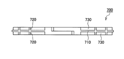
- FIG. 7 is a view of a seal ring according to a conventional example viewed from an outer peripheral surface side
- FIG. 8 is a partially enlarged view thereof.
- a pair of recesses 730 extending in the circumferential direction are provided on both sides in the width direction on the outer peripheral surface side of the seal ring 700 according to the conventional example.
- a convex portion 710 is formed between the pair of concave portions 730.
- a plurality of ribs 720 connected to the protrusions 710 and extending to the side surfaces of the seal ring are provided in the pair of recesses 730 at intervals in the circumferential direction.
- the rib 720 is configured to extend perpendicular to the projection 710. Therefore, the side wall surface of the projection 710 and the side wall surface of the rib 720 are configured to intersect perpendicularly. Therefore, when the seal ring 700 is used in an environment in which a large amount of foreign matter is contained in the fluid to be sealed (oil or the like), the foreign matter is formed at a portion (corner portion) where the side wall surface of the projection 710 and the side wall surface of the rib 720 intersect. Will easily accumulate. This will be described in more detail with reference to FIG.
- an arrow R1 indicates the rotation direction of the shaft and the seal ring 700 with respect to the housing when the shaft and the housing (both not shown) are relatively rotated.
- Arrow R2 indicates the direction of rotation of the housing with respect to the shaft and seal ring 700.
- the fluid to be sealed flows in the direction of arrow S0 in FIG. If a large amount of foreign matter is contained in the fluid to be sealed, of the four corners where the side wall surface of the convex portion 710 and the side wall surface of the rib 720 intersect, the direction of the flow of the fluid to be sealed (the direction of arrow S0) Foreign matter C accumulates at the corner on the upstream side and on the side where the fluid to be sealed is sealed (see FIG. 8).
- An object of the present invention is to provide a seal ring capable of suppressing foreign matter from being caught in a sliding portion.
- the present invention employs the following means in order to solve the above problems.
- the seal ring of the present invention The fluid pressure in the area to be sealed, which is mounted in an annular groove provided on the outer periphery of the shaft and seals the annular gap between the shaft and the housing, which rotates relatively, so that the fluid pressure changes.
- a seal ring for holding In the seal ring which is in close contact with the low-pressure side wall surface of the annular groove and slides on the inner peripheral surface of a shaft hole through which the shaft is inserted in the housing, On the outer peripheral surface side, a pair of concave portions extending in the circumferential direction is provided on both sides in the width direction, so that a convex portion is formed between the pair of concave portions, and the convex portion is formed in the pair of concave portions.
- a plurality of ribs connected to the part and extending to the side surface of the seal ring are provided at intervals in the circumferential direction, Of the plurality of ribs, the plurality of ribs arranged on the sealing target area side have a side wall surface on an upstream side in a rotational direction of the housing relative to the shaft, and each of the plurality of ribs extends from the protrusion to the side of the seal ring. And an inclined surface that is inclined from the upstream side to the downstream side in the relative rotation direction of the housing as going toward.
- a pair of concave portions extending in the circumferential direction are provided on both sides in the width direction, so that at the concave portion, fluid pressure from the inner peripheral surface side and from the outer peripheral surface side Can be offset.
- the sliding resistance can be reduced.
- a plurality of ribs connected to the convex portions and extending to the side surfaces of the seal ring are provided at intervals in the circumferential direction in the pair of concave portions, the posture of the seal ring in the annular groove can be stabilized.
- the plurality of ribs arranged on the side of the seal target area are arranged such that the side walls on the upstream side in the direction of relative rotation of the housing with respect to the shaft all rotate relative to the housing from the convex portion toward the side surface of the seal ring. It is constituted by an inclined surface inclined from the upstream side to the downstream side in the direction. Therefore, even if foreign matter in the fluid to be sealed enters the recess, the foreign matter is discharged out of the recess by the inclined surface. Thereby, it is possible to suppress the accumulation of foreign matter in the concave portion.
- All of the plurality of ribs may be configured to gradually decrease in width from the protrusion to the side surface of the seal ring.
- the above-described inclined surface can be made to exist regardless of the relative rotation direction between the shaft and the housing, and regardless of which side of the both sides of the seal ring is the sealing target area. .
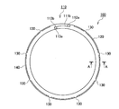
- FIG. 1 is a side view of a seal ring according to an embodiment of the present invention.
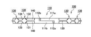
- FIG. 2 is a view of the seal ring according to the embodiment of the present invention as viewed from the outer peripheral surface side.
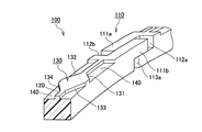
- FIG. 3 is a partially cutaway perspective view of the seal ring according to the embodiment of the present invention.
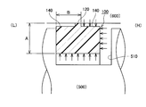
- FIG. 4 is a schematic sectional view of a sealing structure using a seal ring according to the embodiment of the present invention.
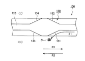
- FIG. 5 is a partially enlarged view of the seal ring according to the embodiment of the present invention as viewed from the outer peripheral surface side.
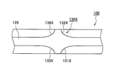
- FIG. 6 is a view showing a modification of the rib according to the embodiment of the present invention.
- FIG. 7 is a view of a conventional seal ring viewed from the outer peripheral surface side.
- FIG. 8 is a partially enlarged view of a view seen from an outer peripheral surface side of a seal ring according to a conventional example.
- the seal ring according to the present embodiment is used for sealing an annular gap between a relatively rotating shaft and a housing in order to maintain a hydraulic pressure in a transmission such as an AT or a CVT for an automobile. It is preferably used.
- high pressure side means a side that becomes high pressure when a differential pressure is generated on both sides of the seal ring
- low pressure side means that a differential pressure is generated on both sides of the seal ring. Means the side where the pressure becomes low.
- FIG. 1 is a side view of a seal ring according to an embodiment of the present invention.
- FIG. 2 is a view of the seal ring according to the embodiment of the present invention as viewed from the outer peripheral surface side, and is a view as viewed from above in FIG.
- FIG. 3 is a partially cutaway perspective view of the seal ring according to the embodiment of the present invention.
- FIG. 4 is a schematic sectional view of a sealing structure using a seal ring according to the embodiment of the present invention. The sectional view of the seal ring in FIG. 4 is an AA sectional view in FIG.
- FIG. 5 is a partially enlarged view of the seal ring according to the embodiment of the present invention as viewed from the outer peripheral surface side.
- the seal ring 100 is mounted in an annular groove 510 provided on the outer periphery of the shaft 500, and the shaft 500 that rotates relatively and the housing 600 (the inner periphery of the shaft hole through which the shaft 500 is inserted in the housing 600). Surface) is sealed.
- the seal ring 100 maintains the fluid pressure in the region to be sealed configured such that the fluid pressure of the fluid to be sealed (in this embodiment, the hydraulic pressure) changes.
- the fluid pressure in the right area in FIG. 4 is configured to change, and the seal ring 100 plays a role of maintaining the fluid pressure in the right sealing area in the figure. I have.
- the fluid pressure in the region to be sealed is low, and there is no load.
- the fluid pressure in the region to be sealed increases.
- the seal ring 100 is made of a resin material such as polyetheretherketone (PEEK), polyphenylenesulfide (PPS), or polytetrafluoroethylene (PTFE). Further, the peripheral length of the outer peripheral surface of the seal ring 100 is configured to be shorter than the peripheral length of the inner peripheral surface of the shaft hole of the housing 600, and is configured to have no interference.
- PEEK polyetheretherketone
- PPS polyphenylenesulfide
- PTFE polytetrafluoroethylene
- This seal ring 100 is provided with an abutment 110 at one location in the circumferential direction.
- a pair of recesses 140 extending in the circumferential direction are provided on both sides in the width direction on the outer peripheral surface side of the seal ring 100.
- a protrusion 120 that slides on the inner peripheral surface of the shaft hole of the housing 600 is provided.
- the bottom surfaces of the pair of recesses 140 are configured to be concentric with the inner peripheral surface of the seal ring 100.
- the side surface of the convex portion 120 is configured to be perpendicular to the bottom surface of the concave portion 140.
- a plurality of ribs 130 connected to the protrusions 120 and extending to the side surfaces of the seal ring are provided in the pair of recesses 140 at intervals in the circumferential direction.
- the abutment portion 110, the concave portion 140, the convex portion 120, and the plurality of ribs 130 provided in the concave portion 140 are formed on an annular member having a rectangular cross section.
- Configuration is only a description of the shape, and does not necessarily mean that a process of forming each of these portions is performed by using an annular member having a rectangular cross section as a material. Needless to say, each part can be obtained by cutting after forming the annular member having a rectangular cross section.
- the seal ring 100 having the convex portion 120 and the plurality of ribs 130 may be manufactured by cutting the concave portion 140 after molding the one having the abutment portion 110 in advance, and the manufacturing method is particularly limited. It is not something to be done.
- the abutment 110 employs a so-called special step cut that is cut in a step-like manner when viewed from both the outer peripheral surface side and both side wall surfaces.
- the first fitting convex portion 111a and the first fitting concave portion 112a are provided on one outer peripheral side via the cut portion, and the first fitting convex portion 111a is provided on the other outer peripheral side.
- a second fitting concave portion 112b fitted with the fitting convex portion 111a and a second fitting convex portion 111b fitted with the first fitting concave portion 112a are provided.
- the inner peripheral surfaces on both sides of the cut portion are formed by flat surfaces 113a and 113b opposed to each other.
- the special step cut is a known technique, its detailed description is omitted, but it has a characteristic of maintaining stable sealing performance even if the circumference of the seal ring 100 changes due to thermal expansion and contraction.
- the case of the special step cut is shown as an example of the abutment portion 110, but the abutment portion 110 is not limited to this, and a straight cut, a bias cut, a step cut, or the like may be adopted.
- a low-elasticity material such as PTFE
- the seal ring 100 may be endless without providing the abutment portion 110.
- the pair of recesses 140 are formed in the vicinity of the abutment portion 110 and all around except for the plurality of ribs 130.
- the portion near the abutment portion 110 where the concave portion 140 is not provided, the outer peripheral surface of the convex portion 120, and the outer peripheral surface of the rib 130 are the same surface.
- an annular continuous sealing surface is formed on the outer peripheral surface side of the seal ring 100.
- the outer peripheral surface of the seal ring 100 except for the vicinity of the abutment portion 110, only the outer peripheral surface of the projection 120 and the outer peripheral surface of the rib 130 slide with respect to the inner peripheral surface of the shaft hole.
- the distance (corresponding to the length of the region B) from one side surface of the convex portion 120 to the other side surface of the seal ring 100, and the other side of the convex portion 120 Is set shorter than the distance from the inner peripheral surface of the seal ring 100 to the outer peripheral surface of the projection 120 (corresponding to the length of the region A) (see FIG. 4). (See FIG. 4). Note that the distance from one side surface of the projection 120 to the other side surface of the seal ring 100 and the distance from the other side surface of the projection 120 to one side surface of the seal ring 100 are equal.
- the seal ring 100 has an effective pressure receiving area from the inner peripheral surface side that contributes to the force pressed against the inner peripheral surface of the shaft hole by the fluid pressure. This is smaller than the effective pressure receiving area from the side that contributes to the force pressed against the low pressure side wall surface of the annular groove 510 by the fluid pressure. Therefore, when a differential pressure is generated on both sides of the seal ring 100, the effective pressure receiving area (pressure receiving area) with respect to the seal ring 100 is smaller in the direction toward the outside in the radial direction than in the axial direction. Therefore, the outer peripheral surface of the seal ring 100 can be more reliably slid against the inner peripheral surface of the shaft hole without sliding the seal ring 100 against the annular groove 510.
- each of the plurality of ribs 130 is configured such that the width gradually decreases from the convex portion 120 toward the seal ring side surface. Accordingly, both side surfaces of the rib 130 provided on both sides of the convex portion 120 are each formed by an inclined surface inclined with respect to the circumferential direction.
- both side surfaces of the rib 130 provided on both sides of the convex portion 120 are referred to as a first side wall surface 131, a second side wall surface 132, a third side wall surface 133, and a fourth side wall surface for convenience of description (FIG. 2, FIG. 2). See 3,5).
- the sealing structure according to the present embodiment includes a shaft 500, a housing 600, and a seal ring 100 that seals an annular gap between the shaft 500 and the housing 600.
- FIG. 4 shows a state where the engine is started and a differential pressure is generated via the seal ring 100 (a state where the pressure on the right side in the figure is higher than the pressure on the left side).
- the seal ring 100 is formed in the annular groove 510 between the left side wall surface in FIG. The state may be away from the peripheral surface.
- the seal ring 100 is in close contact with the side wall surface on the low pressure side (L) of the annular groove 510 and slides against the inner peripheral surface of the shaft hole. (See FIG. 4).
- the direction in which the fluid pressure acts from the inner peripheral surface side is exactly opposite to the direction in which the fluid pressure acts from the outer peripheral surface side. Note that the arrows in FIG. 4 indicate how the fluid pressure acts on the seal ring 100.
- an increase in pressure on the outer peripheral surface side due to the increase in the fluid pressure due to the seal ring 100 can be suppressed, and the sliding torque can be suppressed low.
- a plurality of ribs 130 are provided in the pair of concave portions 140 so as to be connected to the convex portions 120.
- the posture of the seal ring 100 in the annular groove 510 can be stabilized. That is, the inclination of the seal ring 100 in the annular groove 510 can be suppressed.
- the plurality of ribs 130 are provided, the rigidity of the seal ring 100 is increased, and in particular, the strength in the torsion direction can be increased. Therefore, even in an environment where the differential pressure increases, the deformation of the seal ring 100 is suppressed, and the sealing performance is stably exhibited.
- the plurality of ribs 130 arranged on the sealing target area side are located on the upstream side in the direction of relative rotation of the housing 600 with respect to the shaft 500.
- the wall surface (hereinafter, such a side wall surface is referred to as “specific side wall surface” for convenience of description) is configured as follows. That is, such a specific side wall surface is constituted by an inclined surface which is inclined from the upstream side to the downstream side in the relative rotation direction of the housing 600 as going from the convex portion 120 to the seal ring side surface. . This will be described in more detail with reference to FIG.
- the lower side than the seal ring 100 is the high pressure side (H), that is, the sealing target area side, and the upper side is the low pressure side (L).
- an arrow R1 indicates the rotation direction of the shaft 500 and the seal ring 100 with respect to the housing 600 when the shaft 500 and the housing 600 rotate relatively.
- the arrow R2 indicates the rotation direction of the housing 600 with respect to the shaft 500 and the seal ring 100.
- the fluid to be sealed flows in the direction of arrow S1 in FIG.
- the specific side wall surface is the first side wall surface 131.
- the wall surface becomes the second side wall surface 132.
- the relationship between the high-pressure side (H) and the low-pressure side (L) is such that when the relative rotation direction between the shaft 500 and the housing 600 is switched in the state shown in FIG. It becomes the third side wall surface 133. Further, when the high pressure side (H) and the low pressure side (L) are switched and the relative rotation direction between the shaft 500 and the housing 600 is switched, the specific side wall surface becomes the fourth side wall surface 134.
- the plurality of ribs 130 in the seal ring 100 according to the present embodiment are provided with the specific side wall surfaces as described above.
- the foreign matter C is discharged out of the recess 140 by the side wall surface (inclined surface) (see arrow S1 in FIG. 5). Thereby, it is possible to suppress the accumulation of foreign matter in the concave portion 140.
- each of the plurality of ribs 130 according to the present embodiment is configured so that the width gradually decreases from the convex portion 120 toward the seal ring side surface.
- the specific side wall surface slope Surface
- any one of the first side wall surface 131, the second side wall surface 132, the third side wall surface 133, and the fourth side wall surface 134 is the specific side wall surface.
- the seal ring 100 As described above, according to the seal ring 100 according to the present embodiment, it is possible to prevent the foreign matter C from being caught in the sliding portion between the seal ring 100 and the surface of the shaft hole of the housing 600. As a result, it is possible to suppress the sealing performance from being reduced, and it is possible to suppress sliding wear. Accordingly, in order to reduce the weight, the use of a soft material such as aluminum as the material of the housing 600 can be prevented.
- the side wall surfaces (the first side wall surface 131, the second side wall surface 132, the third side wall surface 133, and the fourth side wall surface 134) of the rib 130 are formed as a plane is shown.
- the side wall surface of the rib in the present invention is not limited to a flat surface.
- the side wall surfaces (the first side wall surface 131X, the second side wall surface 132X, the third side wall surface 133X, and the fourth side wall surface 134X) are formed by curved surfaces. Can also. With such a configuration, each side wall surface of the rib 130X and the side wall surface of the projection 120 can be smoothly connected. It goes without saying that the same operation and effect as in the above embodiment can be obtained in the above configuration.
- seal ring 110 abutment portion 111a first fitting convex portion 111b second fitting convex portion 112a first fitting concave portion 112b second fitting concave portion 113a, 113b planar surface 120 convex portion 130 rib 131 first side wall surface 132 Second side wall surface 133 Third side wall surface 134 Fourth side wall surface 140 Depression 500 Shaft 510 Annular groove 600 Housing C Foreign matter
Landscapes
- Engineering & Computer Science (AREA)
- General Engineering & Computer Science (AREA)
- Mechanical Engineering (AREA)
- Physics & Mathematics (AREA)
- Architecture (AREA)
- Fluid Mechanics (AREA)
- Sealing Devices (AREA)
Abstract
Priority Applications (5)
| Application Number | Priority Date | Filing Date | Title |
|---|---|---|---|
| US16/965,162 US11614169B2 (en) | 2018-08-09 | 2019-08-09 | Seal ring |
| KR1020207018975A KR102410100B1 (ko) | 2018-08-09 | 2019-08-09 | 실 링 |
| EP19845999.2A EP3835631B1 (fr) | 2018-08-09 | 2019-08-09 | Bague d'étanchéité |
| JP2020535903A JP6872671B2 (ja) | 2018-08-09 | 2019-08-09 | シールリング |
| CN201980007160.XA CN111566396A (zh) | 2018-08-09 | 2019-08-09 | 密封环 |
Applications Claiming Priority (2)
| Application Number | Priority Date | Filing Date | Title |
|---|---|---|---|
| JP2018-150722 | 2018-08-09 | ||
| JP2018150722 | 2018-08-09 |
Publications (1)
| Publication Number | Publication Date |
|---|---|
| WO2020032236A1 true WO2020032236A1 (fr) | 2020-02-13 |
Family
ID=69414302
Family Applications (1)
| Application Number | Title | Priority Date | Filing Date |
|---|---|---|---|
| PCT/JP2019/031569 Ceased WO2020032236A1 (fr) | 2018-08-09 | 2019-08-09 | Bague d'étanchéité |
Country Status (6)
| Country | Link |
|---|---|
| US (1) | US11614169B2 (fr) |
| EP (1) | EP3835631B1 (fr) |
| JP (1) | JP6872671B2 (fr) |
| KR (1) | KR102410100B1 (fr) |
| CN (1) | CN111566396A (fr) |
| WO (1) | WO2020032236A1 (fr) |
Families Citing this family (1)
| Publication number | Priority date | Publication date | Assignee | Title |
|---|---|---|---|---|
| CN114072602B (zh) * | 2019-07-12 | 2024-04-05 | Nok株式会社 | 密封环 |
Citations (3)
| Publication number | Priority date | Publication date | Assignee | Title |
|---|---|---|---|---|
| JPH10141506A (ja) * | 1996-11-07 | 1998-05-29 | Nok Corp | 密封装置 |
| WO2014041832A1 (fr) * | 2012-09-13 | 2014-03-20 | Nok株式会社 | Bague d'étanchéité |
| WO2014196403A1 (fr) * | 2013-06-03 | 2014-12-11 | Nok株式会社 | Bague d'étanchéité |
Family Cites Families (11)
| Publication number | Priority date | Publication date | Assignee | Title |
|---|---|---|---|---|
| GB531098A (en) * | 1939-06-05 | 1940-12-30 | Automotive Prod Co Ltd | Improvements in or relating to piston and like packing rings |
| JP2008002648A (ja) * | 2006-06-26 | 2008-01-10 | Nok Corp | シールリング |
| CN102052463B (zh) * | 2009-10-28 | 2013-05-22 | 财团法人工业技术研究院 | 真空旋转动力传输装置 |
| US9388705B2 (en) * | 2012-03-12 | 2016-07-12 | Nok Corporation | Sealing device |
| US20140175755A1 (en) * | 2012-12-21 | 2014-06-26 | Parker-Hannifin Corporation | Shaft seal ring with anti-rotation features |
| CN105074298B (zh) * | 2013-02-20 | 2019-11-22 | Nok株式会社 | 密封装置 |
| US10711839B2 (en) * | 2013-04-15 | 2020-07-14 | Stein Seal Company | Circumferential seal with bifurcated flow along multi-axis stepped grooves |
| US10190689B2 (en) * | 2015-03-16 | 2019-01-29 | Nok Corporation | Seal ring |
| CN205244387U (zh) * | 2015-12-10 | 2016-05-18 | 中国石油大学(华东) | 双向旋转花瓣型端面机械密封结构 |
| JP2017172617A (ja) * | 2016-03-22 | 2017-09-28 | Nok株式会社 | 密封装置 |
| DE112018004245B4 (de) * | 2017-09-21 | 2025-05-22 | Nok Corporation | Dichtring |
-
2019
- 2019-08-09 JP JP2020535903A patent/JP6872671B2/ja active Active
- 2019-08-09 US US16/965,162 patent/US11614169B2/en active Active
- 2019-08-09 WO PCT/JP2019/031569 patent/WO2020032236A1/fr not_active Ceased
- 2019-08-09 EP EP19845999.2A patent/EP3835631B1/fr active Active
- 2019-08-09 KR KR1020207018975A patent/KR102410100B1/ko active Active
- 2019-08-09 CN CN201980007160.XA patent/CN111566396A/zh active Pending
Patent Citations (4)
| Publication number | Priority date | Publication date | Assignee | Title |
|---|---|---|---|---|
| JPH10141506A (ja) * | 1996-11-07 | 1998-05-29 | Nok Corp | 密封装置 |
| WO2014041832A1 (fr) * | 2012-09-13 | 2014-03-20 | Nok株式会社 | Bague d'étanchéité |
| WO2014196403A1 (fr) * | 2013-06-03 | 2014-12-11 | Nok株式会社 | Bague d'étanchéité |
| JP6191689B2 (ja) | 2013-06-03 | 2017-09-06 | Nok株式会社 | シールリング |
Non-Patent Citations (1)
| Title |
|---|
| See also references of EP3835631A4 |
Also Published As
| Publication number | Publication date |
|---|---|
| US11614169B2 (en) | 2023-03-28 |
| KR20200088478A (ko) | 2020-07-22 |
| EP3835631C0 (fr) | 2023-06-28 |
| EP3835631B1 (fr) | 2023-06-28 |
| US20210356044A1 (en) | 2021-11-18 |
| JPWO2020032236A1 (ja) | 2020-12-17 |
| EP3835631A4 (fr) | 2022-04-20 |
| EP3835631A1 (fr) | 2021-06-16 |
| KR102410100B1 (ko) | 2022-06-22 |
| CN111566396A (zh) | 2020-08-21 |
| JP6872671B2 (ja) | 2021-05-19 |
Similar Documents
| Publication | Publication Date | Title |
|---|---|---|
| JP6615833B2 (ja) | シールリング | |
| JP6032347B2 (ja) | 密封装置 | |
| JP6687162B2 (ja) | シールリング | |
| JP6913186B2 (ja) | シールリング | |
| JP7377891B2 (ja) | 密封装置 | |
| WO2020032236A1 (fr) | Bague d'étanchéité | |
| WO2014045838A1 (fr) | Dispositif d'étanchéité | |
| JP6458905B2 (ja) | シールリング | |
| WO2016140056A1 (fr) | Bague d'étanchéité | |
| JP5598000B2 (ja) | シールリング | |
| JP5076475B2 (ja) | シールリング及び密封構造 | |
| JP2021188709A (ja) | シールリング | |
| WO2024128135A1 (fr) | Bague d'étanchéité et structure d'étanchéité | |
| JP2020041547A (ja) | シールリング |
Legal Events
| Date | Code | Title | Description |
|---|---|---|---|
| 121 | Ep: the epo has been informed by wipo that ep was designated in this application |
Ref document number: 19845999 Country of ref document: EP Kind code of ref document: A1 |
|
| ENP | Entry into the national phase |
Ref document number: 2020535903 Country of ref document: JP Kind code of ref document: A Ref document number: 20207018975 Country of ref document: KR Kind code of ref document: A |
|
| NENP | Non-entry into the national phase |
Ref country code: DE |
|
| ENP | Entry into the national phase |
Ref document number: 2019845999 Country of ref document: EP Effective date: 20210309 |