WO2020036111A1 - Dispositif de commande et procédé de commande - Google Patents
Dispositif de commande et procédé de commande Download PDFInfo
- Publication number
- WO2020036111A1 WO2020036111A1 PCT/JP2019/031276 JP2019031276W WO2020036111A1 WO 2020036111 A1 WO2020036111 A1 WO 2020036111A1 JP 2019031276 W JP2019031276 W JP 2019031276W WO 2020036111 A1 WO2020036111 A1 WO 2020036111A1
- Authority
- WO
- WIPO (PCT)
- Prior art keywords
- leg
- wheel
- pad portion
- control device
- moving body
- Prior art date
- Legal status (The legal status is an assumption and is not a legal conclusion. Google has not performed a legal analysis and makes no representation as to the accuracy of the status listed.)
- Ceased
Links
Images


Classifications
-
- B—PERFORMING OPERATIONS; TRANSPORTING
- B62—LAND VEHICLES FOR TRAVELLING OTHERWISE THAN ON RAILS
- B62D—MOTOR VEHICLES; TRAILERS
- B62D57/00—Vehicles characterised by having other propulsion or other ground- engaging means than wheels or endless track, alone or in addition to wheels or endless track
- B62D57/02—Vehicles characterised by having other propulsion or other ground- engaging means than wheels or endless track, alone or in addition to wheels or endless track with ground-engaging propulsion means, e.g. walking members
- B62D57/032—Vehicles characterised by having other propulsion or other ground- engaging means than wheels or endless track, alone or in addition to wheels or endless track with ground-engaging propulsion means, e.g. walking members with alternately or sequentially lifted supporting base and legs; with alternately or sequentially lifted feet or skid
-
- B—PERFORMING OPERATIONS; TRANSPORTING
- B25—HAND TOOLS; PORTABLE POWER-DRIVEN TOOLS; MANIPULATORS
- B25J—MANIPULATORS; CHAMBERS PROVIDED WITH MANIPULATION DEVICES
- B25J5/00—Manipulators mounted on wheels or on carriages
- B25J5/007—Manipulators mounted on wheels or on carriages mounted on wheels
-
- B—PERFORMING OPERATIONS; TRANSPORTING
- B25—HAND TOOLS; PORTABLE POWER-DRIVEN TOOLS; MANIPULATORS
- B25J—MANIPULATORS; CHAMBERS PROVIDED WITH MANIPULATION DEVICES
- B25J9/00—Program-controlled manipulators
- B25J9/0009—Constructional details, e.g. manipulator supports, bases
-
- B—PERFORMING OPERATIONS; TRANSPORTING
- B62—LAND VEHICLES FOR TRAVELLING OTHERWISE THAN ON RAILS
- B62D—MOTOR VEHICLES; TRAILERS
- B62D57/00—Vehicles characterised by having other propulsion or other ground- engaging means than wheels or endless track, alone or in addition to wheels or endless track
- B62D57/02—Vehicles characterised by having other propulsion or other ground- engaging means than wheels or endless track, alone or in addition to wheels or endless track with ground-engaging propulsion means, e.g. walking members
- B62D57/028—Vehicles characterised by having other propulsion or other ground- engaging means than wheels or endless track, alone or in addition to wheels or endless track with ground-engaging propulsion means, e.g. walking members having wheels and mechanical legs
-
- B—PERFORMING OPERATIONS; TRANSPORTING
- B25—HAND TOOLS; PORTABLE POWER-DRIVEN TOOLS; MANIPULATORS
- B25J—MANIPULATORS; CHAMBERS PROVIDED WITH MANIPULATION DEVICES
- B25J9/00—Program-controlled manipulators
- B25J9/16—Program controls
- B25J9/1694—Program controls characterised by use of sensors other than normal servo-feedback from position, speed or acceleration sensors, perception control, multi-sensor controlled systems, sensor fusion
Definitions
- the present disclosure relates to a control device and a control method.
- robots have been increasingly used not only in production sites such as factories, but also in public facilities or living spaces. For this reason, for example, development of various robots such as a legged walking robot that can move on uneven terrain that is not paved has been promoted.
- the legged walking robot can cope with a walking surface having irregularities such as a path or an uneven ground where an obstacle exists, and a discontinuous walking surface such as a staircase or a ladder, and thus has excellent ground adaptability. It is expected as a mobile object.
- a legged walking robot has high ground adaptability, but has a lower moving speed or efficiency than a wheeled moving object. This is because the walking motion is performed by the reciprocating motion of each leg, so that the energy conversion efficiency of the legged walking robot is lower than that of the wheeled moving body that can directly convert the rotation of the motor into the rotation of the wheels. This is because
- Patent Literature 1 discloses a bipedal walking robot in which wheels are arranged on the soles of legs.
- the robot disclosed in Patent Literature 1 can perform both walking with legs and running with wheels.
- Patent Literature 1 sufficient consideration has not been given to a wheel brake (also referred to as braking) mechanism disposed on the sole of the leg of the robot.
- a wheel brake also referred to as braking
- a disc brake or a drum brake is generally used as a wheel brake mechanism.
- the disc brake or the drum brake has a large mechanism, if the disc brake or the drum brake is used as a brake mechanism for the wheels of the legs, the mass and inertia of the legs are greatly increased. In such a case, the torque required for the walking movement by the legs increases. Therefore, a leg-wheel type mobile robot provided with a disc brake or a drum brake on the wheel of the leg requires more energy during walking movement and requires a larger actuator.
- a control unit that controls a posture of a moving body including a plurality of legs having at least one or more joints, wherein the legs are provided at a tip of the legs, and the legs are grounded.
- the arithmetic device includes controlling a posture of a moving object including a plurality of legs having at least one or more joints, wherein the legs are provided at a tip of the legs, A wheel body that grounds the leg portion, and a pad portion provided on at least one side surface of the wheel body and having a higher frictional resistance with a ground contact surface than the wheel body, a pitch axis direction of the moving body A control method of controlling the braking force acting on the moving body from the ground contact surface by controlling the posture of the leg portion in the above.
- the posture of the leg is controlled in the pitch axis direction, and the contact portion between the leg and the ground is changed to a pad portion having a higher frictional resistance than the wheel body, so that the leg and the contact surface can be formed.
- the friction between the two can be increased.
- FIG. 2 is an explanatory diagram schematically illustrating wheels used in the technology according to the present disclosure. It is explanatory drawing which shows typically the modification of the wheel shown to FIG. 4A. It is a perspective view showing typically other examples of the wheel used for the art concerning this indication.
- 1 is a perspective view schematically illustrating a leg-wheeled robot used in the technology according to the present disclosure.
- FIG. 9 is a schematic explanatory diagram showing the posture of the leg-wheeled robot at each point in the flowchart shown in FIG. 8.
- FIG. 9 is a schematic explanatory diagram showing the posture of the leg-wheeled robot at each point in the flowchart shown in FIG. 8.
- FIG. 9 is a schematic explanatory diagram showing the posture of the leg-wheeled robot at each point in the flowchart shown in FIG. 8. It is explanatory drawing which shows typically the leg-wheel type robot which concerns on a 1st modification.
- FIG. 9 is a schematic explanatory diagram showing the posture of the leg-wheeled robot at each point in the flowchart shown in FIG. 8.
- FIG. 10B is an explanatory view showing a state where the leg-wheel type robot shown in FIG. 10A grounds an additional pad section. It is explanatory drawing which shows typically the leg wheel type robot which concerns on a 2nd modification.
- FIG. 11B is an explanatory diagram illustrating an example of a mode in which the leg-wheel type robot illustrated in FIG. 11A grounds an additional pad unit.
- FIG. 11B is an explanatory diagram showing another example of a state where the leg-wheel type robot shown in FIG. 11A grounds an additional pad unit. It is a flowchart figure explaining the flow of control of the leg wheel type robot in this modification.
- FIG. 1 is a schematic diagram illustrating an example of a legged robot 1 to which the technology according to the present disclosure can be applied.
- a legged robot 1 to which the technology according to the present disclosure can be applied includes a body 12 and a plurality of legs 10A, 10B, 10C, and 10D (hereinafter, when these are not distinguished from each other, , Collectively also referred to as the legs 10).
- the body 12 includes a control device that controls the posture or movement of the legged robot 1 as a whole, and is supported by the plurality of legs 10.
- the body 12 may include a control device that controls the posture of the leg 10.
- the control device provided in the body 12 cooperates and controls the driving of each of the legs 10 based on sensing information from various sensors provided in each of the legs 10. Under the control of the control device, the legged robot 1 can walk using the legs 10.
- a plurality of legs 10 are attached to the body 12 and support the body 12.
- the leg 10 may be configured with a link structure including at least one or more joints and a link rotatably coupled to the joint.
- the legs 10A, 10B, 10C, and 10D may have the same link structure or different link structures.
- the number of the legs 10 may be at least two or more to enable the legged robot 1 to walk, and the upper limit is not particularly limited. However, in order to improve the posture or walking stability of the legged robot 1, the number of the legs 10 may be four or more.
- the leg 10 can make the legged robot 1 walk by controlling the posture of the leg 10 by a drive motor based on a command from a control device provided in the body 12.
- FIG. 2 is a schematic diagram illustrating a specific example of the structure of the leg 10 of the legged robot 1.
- the leg 10 includes a link mechanism 52, a motor 62, and a pair of non-circular gears 80.
- the link mechanism 52 is configured to be able to expand and contract according to the power output from the motor 62.
- the power output from the motor 62 is output to the link mechanism 52 via the pair of non-circular gears 80.
- the pair of non-circular gears 80 are a pair of rotating bodies, and output the power output from the motor 62 to the link mechanism 52 at a reduction ratio according to the attitude of the link mechanism 52.
- the pair of non-circular gears 80 includes an input-side gear 82 and an output-side gear 81, and functions as a transmission mechanism that reduces and outputs the power input from the motor 62.
- a plurality of teeth meshing with each other are provided in a region where the input side gear 82 and the output side gear 81 are in contact with each other, and the output side gear 81 may rotate according to the rotation of the input side gear 82.
- the pair of non-circular gears 80 can change the reduction ratio in accordance with the attitude of the link mechanism 52 because the rotation angle of the output gear 81 has nonlinearity with respect to the rotation angle of the input gear 82. It may be realized.
- the rotation shaft of the input gear 82 may be directly connected to the rotation shaft of the motor 62, or may be connected via one or more circular gears. Note that the pair of non-circular gears 80 is also simply referred to as a non-circular gear 80.
- the link mechanism 52 is constituted by a plurality of links. Specifically, the link mechanism 52 includes a link 41, a link 42 that is a part of the output side gear 81, a link 44, a link 46, a link 47, and a link 48.
- the link mechanism 52 constitutes a trapezoidal link mechanism.
- the link 41, the link 42, the link 44, and the link 46 constitute a trapezoidal four-node link mechanism in which the link lengths of the links facing each other are different.
- the link 41 is provided with the pair of non-circular gears 80 and the motor 62 described above. Specifically, the input gear 82 and the motor 62 are provided at one end of the link 41, and the output gear 81 is provided closer to the center of the link 41 in the direction in which the link 41 extends than the input gear 82.
- the input side gear 82 and the output side gear 81 are respectively connected to the link 41 via a rotation shaft, and are provided rotatably with respect to the link 41. However, the positions of the rotation shafts of the input gear 82 and the output gear 81 are fixed relative to the link 41.
- the motor 62 is provided fixed to the link 41.
- the link 41 is rotatably connected to the body 12 at one end. Specifically, the link 41 is connected to the body 12 at one end so as to be rotatable around the rotation axis of the input gear 82.
- the link 41 is coupled to the center of the link 46 at the other end so as to be rotatable about the shaft 30 as a rotation axis, and is rotatable at the other end about the shaft 68 as a rotation axis.
- the link 42 is configured as a part of the output side gear 81 described above, and is provided rotatably by the power input from the motor 62.
- the output gear 81 includes, for example, a tooth portion 81 a that meshes with a tooth portion of the input gear 82, a mounting portion 81 b coupled to the link 41 via the shaft portion 61, and a protruding portion that protrudes in the radial direction of the shaft portion 61. 81c.
- the protruding portion 81c is provided at a position different from the tooth portion 81a provided in the circumferential direction of the output-side gear 81, and the distal end side of the protruding portion 81c is connected to one end of the link 44 via the shaft portion 64. .
- the link 42 is configured by the mounting portion 81b and the protruding portion 81c. According to this, the link 42 is rotatable integrally with the output gear 81, and is rotatable with respect to the link 41 about the shaft 61 as a rotation axis.
- the link 42 may be configured by a plurality of members, and may not be configured as a part of the output-side gear 81.
- the link 44 is arranged to face the link 41. Specifically, one end of the link 44 is coupled to the other end of the link 42 via the shaft 64 such that the link 44 is rotatable around the shaft 64.
- the link 44 is coupled via one end of the link 46 via the shaft 66 so as to be rotatable around the shaft 66 at the other end.
- the link 46 is arranged to face the link 42. Specifically, one end of the link 46 is coupled to the other end of the link 44 via the shaft 66 so as to be rotatable about the shaft 66 as a rotation axis.
- the link 46 is coupled to the center of the link 48 via the shaft 34 at the other end so as to be rotatable about the shaft 34 as a rotation axis.
- the link 47 is arranged to face the link 46 at a position different from the link 42.
- the link 47 is connected at one end to the center of the link 41 via the shaft 30 so as to be rotatable about the shaft 30 as a rotation axis.
- the link 47 is coupled to one end of the link 46 via the shaft 32 so as to be rotatable around the shaft 32 at the other end.
- the link 48 is arranged on the opposite side of the link 44 to face the link 41.
- the link 48 is coupled at one end to the other end of the link 47 so as to be rotatable about the shaft 32 as a rotation axis, and at one end to be rotatable about the shaft 34 as a rotation axis.
- a ground portion P1 is provided, and the ground portion P1 contacts the ground or the like.
- the link 41, the link 46, the link 47, and the link 48 form a parallel link mechanism.
- the link lengths of the link 41 and the link 48 facing each other substantially match, and the link lengths of the link 46 and the link 47 facing each other substantially match.
- the distance between the shaft portions 30 and 68 and the distance between the shaft portions 32 and 34 substantially match, and the distance between the shaft portions 30 and 32 and the shaft portion The distance between 68 and the shaft portion 34 substantially coincides with each other.
- the leg 10 can expand and contract the link mechanism 52 and control the posture of the leg 10.
- the posture of the link mechanism 52 is such that the balance of the applied moment is maintained in each of the links.
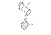
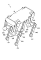
- FIG. 3A is a perspective view schematically showing the leg 10 provided with the wheel mechanism.
- the wheel 131 is provided at a position corresponding to the ground contact portion P1 of the leg 10. Specifically, a wheel 131 is provided at one end of the link 48 at the end of the leg 10. The link 48 is connected to a shaft portion of the wheel 131 via a bearing or the like so that the wheel 131 can rotate.
- the leg-wheel robot in which the wheels 131 are provided on the legs 10 travels at high speed using the wheels 131 on a flat surface such as a pavement, and walks by reciprocating motion of the legs 10 on a running surface having unevenness or the like. It can be performed. Therefore, the leg-wheel type robot provided with the wheels 131 can improve the moving speed or efficiency while maintaining high ground adaptability.
- FIG. 3B is a perspective view schematically showing an example of a wheel mechanism provided on the leg 10.
- the wheel mechanism provided on the leg 10 may be, for example, an omni wheel 132 as shown in FIG. 3B, in addition to the general wheel 131 as shown in FIG. 3A.
- the omni wheel 132 is, for example, a wheel provided with a plurality of small wheels 1323 that are rotatable in the width direction of the wheel main body 1322 on a circumferential portion of the wheel main body 1322 surrounding the shaft portion 1321.
- the small wheels 1323 have a barrel-shaped or spindle-shaped rotating body shape, and a plurality of the small wheels 1323 are arranged so as to be separated from each other so that the rotating shafts face the circumferential direction of the wheel main body 1322.
- the wheel body 1322 including the small wheel 1323 is provided in a circular shape as a whole. Therefore, the omni-wheel 132 can cause the leg-wheeled robot to run in a direction perpendicular to the rotation axis of the wheel main body 1322 by rotating the wheel main body 1322 using the shaft portion 1321 as the rotation axis.
- the omni wheel 132 rotates the small wheel 1323 that is in contact with the ground so that the leg-wheeled robot travels in the width direction of the wheel body 1322. Can be done. That is, the omni-wheel 132 can move the leg-wheel type robot in multiple directions without changing the direction of the wheel main body 1322 by combining the rotations of the small wheel 1323 and the wheel main body 1322.
- a braking mechanism such as a disc brake or a drum brake
- the mass and the inertia of the leg 10 greatly increase. Therefore, providing a disc brake or a drum brake on the wheel mechanism of the leg 10 increases the driving torque of the leg 10 during walking movement.
- the disc brake or the drum brake or the like can brake the entire rotation of the wheel main body 1322, but the rotation of each of the small wheels 1323. It is difficult to brake. Therefore, in the omni-wheel 132, even if braking is performed by a disc brake, a drum brake, or the like, the small wheel 1323 rotates, which makes it difficult to stop the leg-wheeled robot.
- the technology according to the present disclosure has been conceived in view of the above circumstances.
- the technology according to the present disclosure makes it possible to apply a braking force to a leg-wheel robot with a simpler and lighter mechanism.
- to ground means that a member comes into contact with the ground.
- FIG. 4A is an explanatory diagram schematically illustrating a wheel used in the technology according to the present disclosure
- FIG. 4B is an explanatory diagram schematically illustrating a modified example of the wheel illustrated in FIG. 4A
- FIG. 5 is a perspective view schematically illustrating another example of the wheel used in the technology according to the present disclosure.
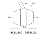
- the wheel 231 used in the technology according to the present disclosure includes a wheel main body 2311 provided at one end of the link 24 at the end of the leg, and a wheel 231 provided on at least one side surface of the wheel main body 2311.
- the wheel main body 2311 is substantially disc-shaped, and although not shown in detail in FIG. 4A, the link 24 at the end of the leg portion is rotatable around a center of the substantially disc-shaped via a bearing or the like as a rotation axis. Connected to.
- the pad portion 2312 is provided on one or both side surfaces of the wheel main body 2311 with a material having higher frictional resistance with the ground contact surface than the wheel main body 2311.
- the pad portion 2312 may be provided fixed to the wheel main body 2311 so as to rotate with the wheel main body 2311 if friction resistance at the time of ground contact is high, or provided separately from the wheel main body 2311 so as not to rotate. You may.
- the technology according to the present disclosure controls the posture of the leg of the leg-wheeled robot in the pitch axis direction, and controls the ground contact portion between the leg and the ground to either the wheel main body 2311 or the pad portion 2312, so that the leg is controlled. It controls the braking force acting on the wheeled robot. Specifically, the technology according to the present disclosure increases the frictional resistance between the leg and the ground surface by tilting the leg of the leg-wheeled robot in the pitch axis direction and bringing the pad portion 2312 into contact with the ground surface. And a braking force is applied to the leg-wheeled robot.
- the pad portion 2312 may be formed of a material having higher frictional resistance with the ground contact surface than the wheel main body 2311.
- the pad portion 2312 may be formed of a material similar to a general material used for a brake pad.
- the pad portion 2312 may be provided in a surface shape such that the frictional resistance with the ground contact surface is higher than that of the wheel main body 2311.
- the pad portion 2312 may be formed of a material similar to a general material used for the wheel main body 2311.
- the pad portion 2312 when the pad portion 2312 is provided separately from the wheel body 2311 so as not to rotate, the pad portion 2312 has a higher rolling resistance to the ground contact surface than the wheel body 2311.
- the pad portion 2312 can also make the frictional resistance against the ground contact surface higher than that of the wheel main body 2311 by such a configuration.
- the shape of the pad portion 2312 may be any shape as long as it has a thickness in the pitch axis direction of the leg-wheeled robot.
- the shape described below may be used.
- the shape of the pad portion 2312 may be such that the cross-sectional shape at an arbitrary cut surface perpendicular to the roll axis of the leg-wheeled robot is substantially semicircular or substantially sectorial. More specifically, the shape of the pad portion 2312 may be a hemispherical shape or a semi-elliptical shape.
- the inclination of the wheel 231 controls which of the wheel main body 2311 and the pad portion 2312 is grounded. Therefore, the shape of the pad portion 2312 may be a shape that can be easily grounded by the inclination of the wheel 231.
- the shape of the pad portion 2312 is a shape in which a cross-sectional shape in a cross section perpendicular to the roll axis of the leg-wheeled robot is a substantially semicircular shape or a substantially fan-shaped shape
- the shape of the pad portion 2312 is a wheel body 2311. From which the curved surface becomes substantially continuous. According to this, the wheel 231 can smoothly switch the ground contact point with the ground between the wheel main body 2311 and the pad portion 2312 according to the inclination of the wheel 231.
- the shape of the pad portion 2312 may be a cross-sectional shape in which a part of the above-described substantially semicircular or substantially fan-shaped arc is replaced by a straight line perpendicular to the ground plane.
- the shape of the pad portion may be a shape obtained by cutting a part of a hemispherical or semi-elliptical spherical curved surface by a plane perpendicular to the roll axis of the leg-wheeled robot. More specifically, the shape of the pad portion 2312 may be a bowl shape as shown in FIG. 4A.
- the flat surface provided on a part of the hemispherical or semi-elliptical spherical curved surface of the pad portion 2312 is grounded, so that the grounded surface is a slope or the like. Even if it stops, it will be possible to stop stably.
- the pad portion 2312 may be provided such that the frictional resistance changes according to the distance from the wheel main body 2311. Specifically, as shown in FIG. 4B, the pad portion 2312 may be provided so that the frictional resistance increases as the distance from the wheel body 2311 increases. According to this configuration, the pad portion 2312 can control the magnitude of the braking force applied to the leg portion by controlling the contact surface with the ground.
- the leg-wheeled robot can make the pad portion 2312 ground by tilting the leg portion 10 from the state where the wheel main body 2311 is grounded, and can exert a braking force on the leg portion. Further, the leg-wheeled robot can exert a greater braking force on the legs by increasing the inclination of the legs and grounding the outside of the pad portion 2312.
- the contact portion can be gradually changed from the wheel main body 2311 having a low frictional resistance to the pad portion 2312 having a high frictional resistance.
- the pad portion 2312 has a bowl shape, after the leg-wheeled robot stops, a flat surface provided on a part of the curved surface of the pad portion 2312 is grounded, The leg-wheeled robot can be stopped stably.
- the pad portion 2312 may be formed with a different material according to the distance from the wheel main body 2311 so that the frictional resistance varies according to the distance from the wheel main body 2311.
- the pad portion 2312 may change the surface shape according to the distance from the wheel main body 2311 so that the frictional resistance varies according to the distance from the wheel main body 2311.
- the pad portion 2312 may be provided to have different characteristics depending on the distance from the wheel main body 2311.
- the material and surface shape of the pad portion 2312 may be changed at each distance from the wheel main body 2311 so as to have the characteristics of a studless tire, a snow tire, or a spike tire for snowy roads and frozen roads.
- the leg-wheeled robot changes the posture of the leg, and switches the ground contact portion from the wheel main body 2311 to the pad portion 2312, so that the contact surfaces of the wheels 231 are suitable for different running surfaces. Can be changed.
- the wheel mechanism used in the technology according to the present disclosure may be an omni wheel.
- the omni wheel 232 includes a shaft portion 2321 serving as a rotation axis of the omni wheel 232, and a plurality of small wheels 2323 provided in a belt shape in a circumferential direction of the shaft portion 2321.
- a pad portion 2314 provided on at least one side surface of the plurality of small wheels 2323 provided in a belt shape and having a higher frictional resistance with respect to the ground contact surface than the small wheels 2323 may be provided.
- an omni wheel 132 having a structure as shown in FIG. 3B may be used as the wheel mechanism used in the technology according to the present disclosure.
- the omni wheel 132 can perform the same function as the omni wheel 232 shown in FIG. 5 by providing the pad portion 2312 shown in FIG. 5 on the side surface of the shaft portion 1321.
- the shaft portion 2321 is provided so as to penetrate the omni wheel 232 in the width direction, and functions as a rotating shaft that rotates the entire omni wheel 232.
- the shaft portion 2321 may be coupled to, for example, a link at the end of a leg (not shown) in the width direction of the omni wheel 232.
- the small wheel 2323 is rotatably provided in a barrel-shaped or spindle-shaped rotating body shape.
- a plurality of small wheels 2323 may be provided in a belt shape in the circumferential direction of the shaft portion 2321.
- the plurality of small wheels 2323 may be provided in a barrel shape or a spindle shape extending in a direction oblique to the pitch axis direction of the leg-wheeled robot, and a plurality of small wheels 2323 may be provided in a belt shape in the circumferential direction of the shaft portion 2321.
- the small wheel 2323 is provided to be rotatable about a direction oblique to the pitch axis direction of the leg-wheeled robot as a rotation axis.
- the small wheel 2323 allows the leg-wheeled robot to travel in each of the pitch axis direction and the roll axis direction of the leg-wheeled robot by rotation.
- a leg-wheeled robot provided with an omni-wheel 232
- the forces traveling in the pitch axis direction are canceled out, and the roll axis You can travel in the direction.
- the leg-wheeled robot by rotating the omni-wheels 232 of the legs arranged in the roll axis direction of the leg-wheeled robot, the forces traveling in the roll axis direction are canceled out, and the vehicle travels in the pitch axis direction. Can be.
- the pad portion 2324 is provided on both side surfaces of the plurality of small wheels 2323 provided in a belt shape with a material having higher friction resistance with the ground contact surface than the small wheels 2323. Specifically, the pad portions 2324 are provided on both side surfaces of the plurality of small wheels 2323 so as to sandwich both ends of the small wheel 2323 in a direction oblique to the pitch axis direction.
- the pad portion 2324 may be formed of the same material as the pad portion 2312 described with reference to FIG. 4A. Further, the shape of the pad portion 2324 may be similar to the shape of the pad portion 2312 described with reference to FIG. 4A. Furthermore, the frictional resistance of the pad portion 2324 may change according to the distance from the small wheel 2323.
- a leg-wheeled robot is controlled by controlling a posture of a leg of a leg-wheeled robot in a pitch axis direction and switching a contact portion between the leg 10 and the ground from the wheel body 2311 to the pad portion 2312. It can control the braking force acting on the vehicle. That is, in the technology according to the present disclosure, the braking force caused by the frictional resistance of the pad portion 2312 is applied to the leg portion by grounding the pad portion 2312 having a higher frictional resistance with the ground contact surface than the wheel main body 2311. .
- the leg-wheeled robot can change the posture of the pad portion 2312 provided on the side surface of the wheel main body 2311 without using a large braking mechanism including an actuator such as a disc brake or a drum brake.
- a braking force can be applied to the legs. Therefore, the leg-wheel type robot can apply a brake to the legs with a simpler and lighter configuration.
- the leg-wheel type robot changes the posture of the leg so that the pad 2324 is grounded and the small wheel 2323 is not grounded. Can be. According to this, the leg-wheeled robot can stop more reliably.
- the leg-wheeled robot can prevent the installation position of the leg from moving due to an external force or the like without applying a brake to each of the small wheels 2323.
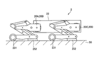
- FIG. 6 is a perspective view schematically illustrating a leg-wheeled robot used in the technology according to the present disclosure.
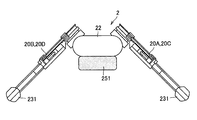
- the leg-wheeled robot 2 used in the technology according to the present disclosure includes, for example, the body 20 and the legs 20A, 20B, and 20C each having the omni wheel 232 illustrated in FIG. 20D (hereinafter, also referred to collectively as the legs 20 when these are not distinguished from each other).
- the leg portion 20 of the leg-wheeled robot 2 may have the wheel 231 shown in FIG. 4A or the like instead of the omni wheel 232.
- the body 22 includes a control device for controlling the posture or movement of the leg-wheeled robot 2, and is supported by the plurality of legs 20.
- the body 22 may include a control device that controls the posture of the leg 20.
- a plurality of legs 20 are attached to the body 22 and support the body 22.
- the leg portion 20 is configured by a link structure including at least one or more joints and a link rotatably coupled to the joint, and a ground of a link at an end of the link structure of the leg portion 20 is provided.
- the portion is provided with an omni wheel 232.
- Each omni wheel 232 of the leg portion 20 is provided so as to apply a driving force in a direction oblique to the pitch axis direction of the leg wheel type robot 2.
- the omni-wheels 232 of the leg 20 adjacent to the leg-wheeled robot 2 in the pitch axis direction and the roll axis direction are provided so as to apply driving force in alternate directions.
- the leg-wheeled robot 2 can move in multiple directions without changing the direction of the leg-wheeled robot 2 by synthesizing the driving force from each of the omni wheels 232 of the leg 20. Become.
- FIG. 7 is a block diagram illustrating a functional configuration of the control device 29.
- the control device 29 includes a movement control unit 291, a posture control unit 292, and a drive control unit 293.
- the movement control unit 291 controls the movement speed of the leg-wheeled robot 2. Specifically, the movement control unit 291 controls the moving speed of the leg-wheeled robot 2 based on a movement plan autonomously determined or based on an external instruction. For example, the movement control unit 291 acquires the current moving speed of the leg-wheeled robot 2 measured by a sensor or the like, and accelerates or moves the leg-wheeled robot 2 so that the current moving speed approaches the target moving speed. Deceleration may be instructed.
- the posture control unit 292 controls the posture of the leg-wheeled robot 2. Specifically, when the movement control unit 291 instructs the deceleration of the leg-wheeled robot 2, the posture control unit 292 controls the posture of the leg-wheeled robot 2 to apply braking to each of the legs 20. Then, the leg-wheeled robot 2 is decelerated.
- the posture controller 292 may apply a brake to each of the legs 20 by inclining each of the legs 20 in the pitch axis direction of the leg-wheeled robot 2 to ground the pad 2312.
- the posture control unit 292 may apply braking to all the legs 20, or may apply braking to some of the legs 20.
- the posture control unit 292 controls the postures of all the legs 20 to decelerate the leg-wheeled robot 2
- the posture control unit 292 can easily stabilize the posture of the leg-wheeled robot 2 during deceleration. Becomes
- the drive control unit 293 controls the drive of each joint of the leg 20. Specifically, the drive control unit 293 controls the drive of the joints provided in each of the legs 20 so that the posture is instructed by the posture control unit 292. For example, the drive control unit 293 controls the output of an actuator that drives a joint provided on each of the legs 20 to control the position of each of the legs 20 to the position specified by the position control unit 292. You may.
- the control device 29 described above controls the operation of hardware such as a CPU (Central Processing Unit) or an MPU (Micro Processing Unit), a RAM (Random Access Memory), and a ROM (Read Only Memory), for example. It can be realized by cooperation with software.
- hardware such as a CPU (Central Processing Unit) or an MPU (Micro Processing Unit), a RAM (Random Access Memory), and a ROM (Read Only Memory), for example. It can be realized by cooperation with software.
- the CPU or the MPU functions as an arithmetic processing unit, and executes all information processing and information arithmetic in the control device 29 according to various programs stored in a ROM or the like.
- the ROM stores programs used by the CPU and operation parameters
- the RAM temporarily stores programs used in the execution of the CPU, parameters that change as appropriate in the execution, and the like.
- a computer program for causing hardware such as a CPU, a ROM, and a RAM built in the control device 29 to exhibit the same functions as those of the components of the control device described above can also be created. Further, a storage medium storing the computer program can be provided.
- FIG. 8 is a flowchart illustrating the flow of control of the leg-wheeled robot 2 by the control device 29.
- 9A to 9C are schematic explanatory diagrams showing the posture of the leg-wheeled robot 2 at each point in the flowchart shown in FIG.
- the leg 20 and the wheel 231 are connected via an elastic member 241 such as a helix spring.
- the leg portion 20 and the wheel 231 can swing relative to each other. Therefore, the wheel 231 can adjust the inclination of the wheel 231 in accordance with the change in the posture of the leg 20 according to the unevenness of the ground contact surface.
- the elastic member 241 can also function as a shock absorber between the leg portion 20 and the wheel 231. According to this, the elastic member 241 can reduce vibration or impact transmitted from the ground contact surface to the body 22.
- the posture control unit 292 opens each of the legs 20 in the pitch axis direction of the leg-wheeled robot 2.
- the leg is set (S105).
- the pad portion 2312 is grounded, and a braking force is applied to the leg-wheeled robot 2 by the pad portion 2312 (S107), so that the leg-wheeled robot 2 is decelerated.
- the posture of the leg-wheeled robot 2 is such that each of the legs 20 extends from the body 22 so that the terminal side of the legs 20 is widened.
- the wheel 231 comes into contact with the ground at the pad portion 2312 on the side surface of the wheel main body 2311, so that a braking force acts on the leg portion 20 from the ground contact surface.
- the movement control unit 291 determines whether to stop the leg-wheeled robot 2 (S109). If the leg-wheeled robot 2 is not stopped (S109 / No), the process returns to step S101, and the movement control unit 291 determines again whether the leg-wheeled robot 2 is accelerated or decelerated. On the other hand, when stopping the leg-wheeled robot 2 (S109 / Yes), the posture controller 292 further opens each of the legs 20 in the pitch axis direction of the leg-wheeled robot 2 (S111).
- each of the leg portions 20 is further opened, and the outer pad portion 2312 is grounded, so that the ground contact surface is formed.
- the braking force acting on the leg 20 can be further increased.
- the movement control unit 291 determines whether or not the leg-wheeled robot 2 has stopped (S113).
- the process returns to step S111, and the posture control unit 292 further opens each leg 20 (S113).
- the posture control unit 292 stops the wheel 231 by tilting the wheel 231 to ground the plane provided on the side surface of the pad unit 2312. The posture is controlled (S115). Thereby, the leg-wheel type robot 2 stops (S121). At this time, as shown in FIG.
- the posture of the leg-wheeled robot 2 is such that each of the legs 20 extends from the body 22 so that the distal end side of the legs 20 is widened. Further, the wheel 231 connected to the leg 20 via the elastic member 241 swings with respect to the leg 20, so that the wheel 231 is grounded on a plane provided on a part of the curved surface of the pad 2312. Accordingly, the leg-wheel type robot 2 can easily maintain the stopped state even when an external force is applied.
- an additional pad portion is further provided on either the body portion 22 or the leg portion 20 of the leg-wheeled robot 2, and when the leg-wheeled robot 2 is suddenly decelerated at the time of sudden stop or the like, the additional pad portion is provided. By contacting the ground, a greater braking force is obtained.
- the configuration of the present modified example will be described separately for each portion where the additional pad portion is provided.
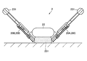
- FIG. 10A is an explanatory diagram schematically showing the leg-wheel type robot 2 according to the first modification.
- FIG. 10B is an explanatory view showing a state where the leg-wheel type robot 2 shown in FIG. 10A has the additional pad portion grounded.
- the additional pad 251 may be provided on a surface of the body 22 of the leg-wheeled robot 2 facing the ground. Specifically, the additional pad 251 may be provided on the abdominal surface of the body 22 of the leg-wheeled robot 2.
- the additional pad portion 251 is provided, for example, with the same material and surface shape as the pad portion 2312 of the wheel 231 described above, so that the frictional resistance is higher than that of the wheel main body 2311. Further, since the additional pad portion 251 is provided on the body portion 22 of the leg-wheel type robot 2, the additional pad portion 251 is provided with a larger area than the pad portion 2312 of the wheel 231. Therefore, the additional pad portion 251 can have a larger contact area when contacting the ground than the pad portion 2312, so that a larger braking force can be obtained at the time of touching the ground, and the leg-wheel type robot 2 can be suddenly moved. It can be stopped.
- the leg portion 20 is extended to the back side of the body portion 22, so that the additional pad portion provided on the abdominal surface side of the body portion 22 251 can contact the ground 50.
- the additional pad portion 251 may be provided on the abdominal surface of the body portion 22 over the entire surface.
- FIG. 11A is an explanatory diagram schematically showing the leg-wheeled robot 2 according to the second modification.
- 11B is an explanatory diagram showing an example of a mode in which the leg-wheel type robot 2 shown in FIG. 11A has the additional pad portion grounded.
- FIG. 11C is a diagram showing the leg-wheeled robot 2 shown in FIG. 11A having the additional pad portion grounded. It is explanatory drawing which shows the other example of the mode made.
- the additional pads 252 and 253 may be provided on the leg 20 of the leg-wheeled robot 2.
- the additional pad portions 252 and 253 may be provided on any link or joint of the link mechanism configuring the leg portion 20.
- the additional pad portions 252 and 253 are provided at links or joints of the links or joints of the leg portion 20 that can be grounded by expansion and contraction of a link mechanism constituting the leg portion 20.
- the additional pad portions 252 and 253 may be provided at a plurality of locations on each of the leg portions 20 or may be provided at one location.
- the additional pad portions 252 and 253 are provided with the same material and surface shape as the pad portion 2312 of the wheel 231 described above, so that the additional pad portions 252 and 253 are provided to have higher friction resistance than the wheel main body 2311.
- a plurality of additional pad portions 252 and 253 can be provided on each of the leg portions 20, it becomes easier to obtain a larger braking force when touching the ground than the pad portion 2312 of the wheel 231. Therefore, the additional pad portions 252 and 253 can stop the leg-wheeled robot 2 suddenly.
- the leg mechanism is provided on one of the links of the leg 20 by contracting the link mechanism constituting the leg 20.
- the additional pad portions 252 and 253 can be brought into contact with the ground 50.
- the leg-wheeled robot 2 causes the leg 20 to contact the ground 50 instead of the body 22 including the control device 29 and the like at the time of an abrupt stop, so that the control device 29 and the like are damaged. Possibilities can be reduced.
- FIG. 12 is a flowchart illustrating the flow of control of the leg-wheeled robot 2 in this modification.
- the posture control unit 292 determines the posture of the body 22 or the leg 20 of the leg-wheeled robot 2. Is controlled to the grounding posture (S119). Thereby, the additional pad portions 251, 252, 253, etc. provided on the body portion 22 or the leg portions 20 are grounded, so that the additional pad portions 251, 252, 253, etc. exert a greater braking force on the leg-wheel type robot 2. Since the voltage is applied, the leg-wheel type robot 2 stops after abrupt deceleration (S121).
- the leg-wheeled robot 2 can be stopped suddenly by using the additional pads 251, 252, 253, etc., without using a large braking mechanism having an actuator such as a disc brake or a drum brake. Can be. Therefore, the leg-wheel robot can apply a brake to the leg 10 with a simpler and lighter configuration.
- the leg-wheeled robot 2 exerts the braking force on the leg 20 by bringing the pad 2312 or the like into contact with the ground, but the present technology is not limited to such an example.
- the leg-wheeled robot 2 may apply a braking force to the leg 20 by bringing the pad 2312 or the like into contact with a wall or ceiling other than the ground.
- a control unit that controls a posture of the moving body including a plurality of legs having at least one or more joints, Said legs, A wheel body provided at the tip of the leg, and grounding the leg; A pad portion provided on at least one side surface of the wheel body and having a higher frictional resistance with a ground contact surface than the wheel body, Has,
- a cross-sectional shape of the pad portion at an arbitrary cut surface perpendicular to a roll axis of the moving body is a substantially semicircular shape or a substantially sectorial shape.
- a cross-sectional shape of the pad portion on the cut surface is a shape in which a part of a substantially semicircular or substantially fan-shaped arc is replaced with a straight line perpendicular to the ground surface. .
- the shape of the pad portion is a shape obtained by cutting a part of a curved surface of a hemisphere by a plane perpendicular to a roll axis of the moving body.
- An additional pad portion is further provided on the body portion or the leg portion of the moving body,
- the control unit controls the posture of the moving body, and controls the braking force applied to the moving body from the ground surface by bringing the additional pad portion into contact with the ground surface.
- the control device according to any one of (1) to (4).
- the control device includes controlling a posture of a moving body including a plurality of legs having at least one or more joints, Said legs, A wheel body provided at the tip of the leg, and grounding the leg; A pad portion provided on at least one side surface of the wheel body and having a higher frictional resistance with a ground contact surface than the wheel body, Has, A control method of controlling a posture of the leg in a pitch axis direction of the moving body to control a braking force applied to the moving body from the ground contact surface.
Landscapes
- Engineering & Computer Science (AREA)
- Mechanical Engineering (AREA)
- Chemical & Material Sciences (AREA)
- Combustion & Propulsion (AREA)
- Transportation (AREA)
- Robotics (AREA)
- Manipulator (AREA)
- Toys (AREA)
Abstract
L'invention concerne un dispositif de commande pourvu d'une unité de commande (29) qui commande l'orientation d'un corps mobile (2) pourvu d'une pluralité de portions de jambe (20) ayant chacune au moins une articulation, chaque portion de jambe comprenant un corps principal de roue (2311) qui est disposé au niveau d'une extrémité distale de la portion de jambe et qui permet à la portion de jambe de prendre appui au sol, et une portion de coussinet (2312) qui est disposée sur au moins une surface latérale du corps principal de roue et qui présente une résistance de frottement supérieure par rapport à une surface d'appui au sol que le corps principal de roue. L'unité de commande commande l'orientation de chaque portion de jambe dans une direction d'axe de tangage du corps mobile, commandant ainsi une force de freinage qui agit sur le corps mobile à partir de la surface d'appui au sol.
Priority Applications (3)
| Application Number | Priority Date | Filing Date | Title |
|---|---|---|---|
| CN201980053072.3A CN112584981A (zh) | 2018-08-16 | 2019-08-07 | 控制装置和控制方法 |
| JP2020537431A JP7276339B2 (ja) | 2018-08-16 | 2019-08-07 | 制御装置及び制御方法 |
| US17/250,598 US20210309309A1 (en) | 2018-08-16 | 2019-08-07 | Control apparatus and control method |
Applications Claiming Priority (2)
| Application Number | Priority Date | Filing Date | Title |
|---|---|---|---|
| JP2018-153165 | 2018-08-16 | ||
| JP2018153165 | 2018-08-16 |
Publications (1)
| Publication Number | Publication Date |
|---|---|
| WO2020036111A1 true WO2020036111A1 (fr) | 2020-02-20 |
Family
ID=69525545
Family Applications (1)
| Application Number | Title | Priority Date | Filing Date |
|---|---|---|---|
| PCT/JP2019/031276 Ceased WO2020036111A1 (fr) | 2018-08-16 | 2019-08-07 | Dispositif de commande et procédé de commande |
Country Status (4)
| Country | Link |
|---|---|
| US (1) | US20210309309A1 (fr) |
| JP (1) | JP7276339B2 (fr) |
| CN (1) | CN112584981A (fr) |
| WO (1) | WO2020036111A1 (fr) |
Cited By (5)
| Publication number | Priority date | Publication date | Assignee | Title |
|---|---|---|---|---|
| CN111301553A (zh) * | 2020-02-26 | 2020-06-19 | 安徽延达智能科技有限公司 | 一种多足机器人 |
| CN111391934A (zh) * | 2020-04-07 | 2020-07-10 | 上海宇航系统工程研究所 | 一种轮腿复合型的机器人移动装置及轮腿复合型机器人 |
| CN111976860A (zh) * | 2020-08-07 | 2020-11-24 | 北京交通大学 | 一种可变形轮腿式机器人 |
| WO2022252863A1 (fr) * | 2021-05-31 | 2022-12-08 | 腾讯科技(深圳)有限公司 | Procédé et appareil de commande pour robot à roues-pattes, robot à roues-pattes et dispositif |
| WO2024195309A1 (fr) * | 2023-03-23 | 2024-09-26 | ソニーグループ株式会社 | Corps mobile |
Families Citing this family (1)
| Publication number | Priority date | Publication date | Assignee | Title |
|---|---|---|---|---|
| CN116728393B (zh) * | 2022-03-01 | 2024-10-18 | 腾讯科技(深圳)有限公司 | 机器人控制方法和机器人 |
Citations (3)
| Publication number | Priority date | Publication date | Assignee | Title |
|---|---|---|---|---|
| JP2006068883A (ja) * | 2004-09-06 | 2006-03-16 | Sony Corp | ロボット装置及びその制御方法、並びに受動車輪装置 |
| JP2012030735A (ja) * | 2010-08-02 | 2012-02-16 | Panasonic Corp | 全方向車輪および移動装置 |
| JP2014161991A (ja) * | 2013-02-28 | 2014-09-08 | Nsk Ltd | ロボットの移動機構及びそれを備えるロボット |
Family Cites Families (5)
| Publication number | Priority date | Publication date | Assignee | Title |
|---|---|---|---|---|
| JP3870257B2 (ja) | 2002-05-02 | 2007-01-17 | 独立行政法人 宇宙航空研究開発機構 | オフセット回転関節を有するロボット |
| JP2006055972A (ja) * | 2004-08-23 | 2006-03-02 | Atsuo Takanishi | 足部走行機構及びそれを備えた2足歩行ロボット |
| JP2006068884A (ja) * | 2004-09-06 | 2006-03-16 | Sony Corp | ロボット装置及びその制御方法、並びに受動車輪装置 |
| JP2006095648A (ja) * | 2004-09-29 | 2006-04-13 | Sony Corp | 脚式移動ロボット及びその制御方法 |
| JP2006095661A (ja) * | 2004-09-30 | 2006-04-13 | Sony Corp | ロボット装置並びにロボット用車輪装置 |
-
2019
- 2019-08-07 WO PCT/JP2019/031276 patent/WO2020036111A1/fr not_active Ceased
- 2019-08-07 CN CN201980053072.3A patent/CN112584981A/zh not_active Withdrawn
- 2019-08-07 JP JP2020537431A patent/JP7276339B2/ja active Active
- 2019-08-07 US US17/250,598 patent/US20210309309A1/en not_active Abandoned
Patent Citations (3)
| Publication number | Priority date | Publication date | Assignee | Title |
|---|---|---|---|---|
| JP2006068883A (ja) * | 2004-09-06 | 2006-03-16 | Sony Corp | ロボット装置及びその制御方法、並びに受動車輪装置 |
| JP2012030735A (ja) * | 2010-08-02 | 2012-02-16 | Panasonic Corp | 全方向車輪および移動装置 |
| JP2014161991A (ja) * | 2013-02-28 | 2014-09-08 | Nsk Ltd | ロボットの移動機構及びそれを備えるロボット |
Cited By (7)
| Publication number | Priority date | Publication date | Assignee | Title |
|---|---|---|---|---|
| CN111301553A (zh) * | 2020-02-26 | 2020-06-19 | 安徽延达智能科技有限公司 | 一种多足机器人 |
| CN111391934A (zh) * | 2020-04-07 | 2020-07-10 | 上海宇航系统工程研究所 | 一种轮腿复合型的机器人移动装置及轮腿复合型机器人 |
| CN111391934B (zh) * | 2020-04-07 | 2021-11-05 | 上海宇航系统工程研究所 | 一种轮腿复合型的机器人移动装置及轮腿复合型机器人 |
| CN111976860A (zh) * | 2020-08-07 | 2020-11-24 | 北京交通大学 | 一种可变形轮腿式机器人 |
| WO2022252863A1 (fr) * | 2021-05-31 | 2022-12-08 | 腾讯科技(深圳)有限公司 | Procédé et appareil de commande pour robot à roues-pattes, robot à roues-pattes et dispositif |
| US12290921B2 (en) | 2021-05-31 | 2025-05-06 | Tencent Technology (Shenzhen) Company Limited | Method and apparatus for controlling wheel-legged robot, wheel-legged robot, and device |
| WO2024195309A1 (fr) * | 2023-03-23 | 2024-09-26 | ソニーグループ株式会社 | Corps mobile |
Also Published As
| Publication number | Publication date |
|---|---|
| JP7276339B2 (ja) | 2023-05-18 |
| CN112584981A (zh) | 2021-03-30 |
| US20210309309A1 (en) | 2021-10-07 |
| JPWO2020036111A1 (ja) | 2021-08-26 |
Similar Documents
| Publication | Publication Date | Title |
|---|---|---|
| WO2020036111A1 (fr) | Dispositif de commande et procédé de commande | |
| KR102139500B1 (ko) | 변형 바퀴 및 이를 구비한 로봇 | |
| JP7072308B2 (ja) | 2足/4輪/4足運動モードを有する再構成可能な足型ロボット | |
| CN107614365B (zh) | 移动平台 | |
| JP4590639B2 (ja) | 脚型車輪型兼用移動装置 | |
| JP6497369B2 (ja) | 走行装置 | |
| JP2009113135A (ja) | 2足型移動機構 | |
| KR101253762B1 (ko) | 구형로봇 | |
| WO2012086604A1 (fr) | Dispositif de nettoyage | |
| JPH0871967A (ja) | 歩行ロボットの歩行制御装置および歩行制御方法 | |
| JP2001150370A (ja) | 脚式移動ロボット及び脚式移動ロボットの動作制御方法 | |
| KR20180067604A (ko) | 휠 구동식 추진 장치를 보유하고 다양한 지지면에서 이동 가능한 샤시 | |
| CN112455155B (zh) | 多模态变形轮及其控制方法、装置、电子设备和存储介质 | |
| JP2006142465A (ja) | 二足歩行ロボットとその歩行制御方法 | |
| JP3888295B2 (ja) | 倒立振子制御のゲインを静止時に下げる歩行ロボット | |
| JP2002307339A (ja) | 脚式移動ロボット及びその制御方法、並びに脚式移動ロボットのための足首構造 | |
| CN108945136A (zh) | 一种关节型球状滚爬转换机器人 | |
| CN212950902U (zh) | 多足机器人 | |
| CN110271622A (zh) | 轮足式结构及轮足式机器人 | |
| JP2005177918A (ja) | ロボット装置並びにロボット装置のためのコンプライアンス装置 | |
| JP4408824B2 (ja) | 多関節歩行装置 | |
| JP4692925B2 (ja) | 脚車輪型移動ロボット及びその動作方法 | |
| JP2001253364A (ja) | 段差乗り越え可能な全方向移動車 | |
| CN110341822A (zh) | 一种球形机器人内部驱动系统 | |
| JP2005046950A (ja) | 4脚移動ロボット |
Legal Events
| Date | Code | Title | Description |
|---|---|---|---|
| 121 | Ep: the epo has been informed by wipo that ep was designated in this application |
Ref document number: 19850590 Country of ref document: EP Kind code of ref document: A1 |
|
| ENP | Entry into the national phase |
Ref document number: 2020537431 Country of ref document: JP Kind code of ref document: A |
|
| NENP | Non-entry into the national phase |
Ref country code: DE |
|
| 122 | Ep: pct application non-entry in european phase |
Ref document number: 19850590 Country of ref document: EP Kind code of ref document: A1 |