WO2020036450A1 - Dispositif d'entraînement de lentille et module de prise de vues le comprenant - Google Patents
Dispositif d'entraînement de lentille et module de prise de vues le comprenant Download PDFInfo
- Publication number
- WO2020036450A1 WO2020036450A1 PCT/KR2019/010397 KR2019010397W WO2020036450A1 WO 2020036450 A1 WO2020036450 A1 WO 2020036450A1 KR 2019010397 W KR2019010397 W KR 2019010397W WO 2020036450 A1 WO2020036450 A1 WO 2020036450A1
- Authority
- WO
- WIPO (PCT)
- Prior art keywords
- lens
- guide
- ball
- guide rail
- camera module
- Prior art date
- Legal status (The legal status is an assumption and is not a legal conclusion. Google has not performed a legal analysis and makes no representation as to the accuracy of the status listed.)
- Ceased
Links
Images


Classifications
-
- G—PHYSICS
- G02—OPTICS
- G02B—OPTICAL ELEMENTS, SYSTEMS OR APPARATUS
- G02B27/00—Optical systems or apparatus not provided for by any of the groups G02B1/00 - G02B26/00, G02B30/00
- G02B27/64—Imaging systems using optical elements for stabilisation of the lateral and angular position of the image
- G02B27/646—Imaging systems using optical elements for stabilisation of the lateral and angular position of the image compensating for small deviations, e.g. due to vibration or shake
-
- G—PHYSICS
- G02—OPTICS
- G02B—OPTICAL ELEMENTS, SYSTEMS OR APPARATUS
- G02B7/00—Mountings, adjusting means, or light-tight connections, for optical elements
- G02B7/02—Mountings, adjusting means, or light-tight connections, for optical elements for lenses
- G02B7/021—Mountings, adjusting means, or light-tight connections, for optical elements for lenses for more than one lens
-
- G—PHYSICS
- G02—OPTICS
- G02B—OPTICAL ELEMENTS, SYSTEMS OR APPARATUS
- G02B7/00—Mountings, adjusting means, or light-tight connections, for optical elements
- G02B7/02—Mountings, adjusting means, or light-tight connections, for optical elements for lenses
- G02B7/023—Mountings, adjusting means, or light-tight connections, for optical elements for lenses permitting adjustment
-
- G—PHYSICS
- G02—OPTICS
- G02B—OPTICAL ELEMENTS, SYSTEMS OR APPARATUS
- G02B7/00—Mountings, adjusting means, or light-tight connections, for optical elements
- G02B7/02—Mountings, adjusting means, or light-tight connections, for optical elements for lenses
- G02B7/025—Mountings, adjusting means, or light-tight connections, for optical elements for lenses using glue
-
- G—PHYSICS
- G02—OPTICS
- G02B—OPTICAL ELEMENTS, SYSTEMS OR APPARATUS
- G02B7/00—Mountings, adjusting means, or light-tight connections, for optical elements
- G02B7/02—Mountings, adjusting means, or light-tight connections, for optical elements for lenses
- G02B7/04—Mountings, adjusting means, or light-tight connections, for optical elements for lenses with mechanism for focusing or varying magnification
-
- G—PHYSICS
- G03—PHOTOGRAPHY; CINEMATOGRAPHY; ANALOGOUS TECHNIQUES USING WAVES OTHER THAN OPTICAL WAVES; ELECTROGRAPHY; HOLOGRAPHY
- G03B—APPARATUS OR ARRANGEMENTS FOR TAKING PHOTOGRAPHS OR FOR PROJECTING OR VIEWING THEM; APPARATUS OR ARRANGEMENTS EMPLOYING ANALOGOUS TECHNIQUES USING WAVES OTHER THAN OPTICAL WAVES; ACCESSORIES THEREFOR
- G03B17/00—Details of cameras or camera bodies; Accessories therefor
- G03B17/02—Bodies
- G03B17/12—Bodies with means for supporting objectives, supplementary lenses, filters, masks, or turrets
-
- G—PHYSICS
- G03—PHOTOGRAPHY; CINEMATOGRAPHY; ANALOGOUS TECHNIQUES USING WAVES OTHER THAN OPTICAL WAVES; ELECTROGRAPHY; HOLOGRAPHY
- G03B—APPARATUS OR ARRANGEMENTS FOR TAKING PHOTOGRAPHS OR FOR PROJECTING OR VIEWING THEM; APPARATUS OR ARRANGEMENTS EMPLOYING ANALOGOUS TECHNIQUES USING WAVES OTHER THAN OPTICAL WAVES; ACCESSORIES THEREFOR
- G03B3/00—Focusing arrangements of general interest for cameras, projectors or printers
- G03B3/10—Power-operated focusing
-
- G—PHYSICS
- G03—PHOTOGRAPHY; CINEMATOGRAPHY; ANALOGOUS TECHNIQUES USING WAVES OTHER THAN OPTICAL WAVES; ELECTROGRAPHY; HOLOGRAPHY
- G03B—APPARATUS OR ARRANGEMENTS FOR TAKING PHOTOGRAPHS OR FOR PROJECTING OR VIEWING THEM; APPARATUS OR ARRANGEMENTS EMPLOYING ANALOGOUS TECHNIQUES USING WAVES OTHER THAN OPTICAL WAVES; ACCESSORIES THEREFOR
- G03B30/00—Camera modules comprising integrated lens units and imaging units, specially adapted for being embedded in other devices, e.g. mobile phones or vehicles
-
- G—PHYSICS
- G03—PHOTOGRAPHY; CINEMATOGRAPHY; ANALOGOUS TECHNIQUES USING WAVES OTHER THAN OPTICAL WAVES; ELECTROGRAPHY; HOLOGRAPHY
- G03B—APPARATUS OR ARRANGEMENTS FOR TAKING PHOTOGRAPHS OR FOR PROJECTING OR VIEWING THEM; APPARATUS OR ARRANGEMENTS EMPLOYING ANALOGOUS TECHNIQUES USING WAVES OTHER THAN OPTICAL WAVES; ACCESSORIES THEREFOR
- G03B5/00—Adjustment of optical system relative to image or object surface other than for focusing
-
- G—PHYSICS
- G03—PHOTOGRAPHY; CINEMATOGRAPHY; ANALOGOUS TECHNIQUES USING WAVES OTHER THAN OPTICAL WAVES; ELECTROGRAPHY; HOLOGRAPHY
- G03B—APPARATUS OR ARRANGEMENTS FOR TAKING PHOTOGRAPHS OR FOR PROJECTING OR VIEWING THEM; APPARATUS OR ARRANGEMENTS EMPLOYING ANALOGOUS TECHNIQUES USING WAVES OTHER THAN OPTICAL WAVES; ACCESSORIES THEREFOR
- G03B2205/00—Adjustment of optical system relative to image or object surface other than for focusing
- G03B2205/0046—Movement of one or more optical elements for zooming
-
- G—PHYSICS
- G03—PHOTOGRAPHY; CINEMATOGRAPHY; ANALOGOUS TECHNIQUES USING WAVES OTHER THAN OPTICAL WAVES; ELECTROGRAPHY; HOLOGRAPHY
- G03B—APPARATUS OR ARRANGEMENTS FOR TAKING PHOTOGRAPHS OR FOR PROJECTING OR VIEWING THEM; APPARATUS OR ARRANGEMENTS EMPLOYING ANALOGOUS TECHNIQUES USING WAVES OTHER THAN OPTICAL WAVES; ACCESSORIES THEREFOR
- G03B2205/00—Adjustment of optical system relative to image or object surface other than for focusing
- G03B2205/0053—Driving means for the movement of one or more optical element
- G03B2205/0069—Driving means for the movement of one or more optical element using electromagnetic actuators, e.g. voice coils
Definitions
- Embodiments relate to a lens driving apparatus and a camera module including the same.
- the camera module captures a subject and stores it as an image or a video, and is mounted on a mobile terminal such as a mobile phone, a laptop, a drone, or a vehicle.
- portable devices such as smartphones, tablet PCs, and laptops have a compact camera module, and the camera module has an autofocus function that aligns the focal length of the lens by automatically adjusting the distance between the image sensor and the lens. Can be done.
- a camera module may perform zooming or zooming out by zooming in or out of a distant subject through a zoom lens.
- the demand for high magnification zooming more than twice that of camera modules is increasing.
- a friction torque is generated when the lens is moved by mechanical movement using a lens driving device for a zooming function in the camera module, and the friction torque reduces driving force, increases power consumption, or decreases control characteristics. Such technical problems are occurring.
- the alignment between the lenses should be well-aligned. Changes or out of focus can adversely affect image quality or resolution.
- the lens housing is used to move the lens housing within a predetermined stroke range by mechanical movement for the zooming function and is stopped by the stopper at the limit of the moving range. Reversal of movement may be possible.
- an impact of a lens mounted on the lens housing may occur due to an impact of the lens housing and the stopper, and the lens decenter or lens tilt may be generated when the zoom movement is reversed. There is a technical problem occurring.
- One of the technical problems of the embodiment is to provide a lens driving apparatus and a camera module including the same, which may reduce friction torque when the lens moves through zooming in the camera module.
- one of the technical problems of the embodiment and the lens driving device that can solve the problem that the lens decentral or lens tilt of the lens mounted on the lens housing due to the impact between the lens housing and the stopper and the same It is to provide a camera module.
- a lens driving device and a camera including the same, which can solve the problems of the reliability of the magnet mounted on the lens housing, damage of the stopper itself, deterioration of the control characteristics due to the impact of the lens housing and the stopper To provide a module.
- the lens driving apparatus includes a base assembly 20; And a first lens assembly 110 including a first lens housing 112 and a first driver housing 114 and disposed in the base assembly 20 and moving in parallel with a predetermined optical axis.
- the first drive unit housing 114 may include at least one first guide rail unit 118 and a first group of balls 119 disposed on the first guide rail unit 118.
- the first guide rail portion 118 may include a first guide body 118a and a first guide groove 118b formed in the first guide body 118a; And a first guide protrusion 118c formed at one side of the first guide body 118a.
- the first lens assembly 110 may be stopped by the balls 119 of the first group disposed on the first guide rails 118.
- the end of the first guide body 118a may be spaced apart from the inner wall 21S of the base 21 by a predetermined first distance S1.
- a cross section of the first guide groove 118b may have a triangular shape.
- the base 21 provided in the base assembly 20 may include a third guide recess 21R in a region corresponding to the first guide groove 118b of the first guide rail unit 118.
- An embodiment includes a ball 119 of a first group in the first guide groove 118b, and the ball 119 of the first group is smaller than the first ball 119a of the first diameter and the first diameter.
- a second ball 119b having a large second diameter may be included, and the second ball 119b may be provided in plural and disposed on both sides of the first ball 119a.
- the second ball 119b is disposed outside the first ball 119a, and the first ball 119a is a third guide recess 21R of the first guide rail 118 and the base 21. Can only touch one).
- the second ball 119b may be in contact with the first guide rail 118 and the third guide recess 21R of the base 21 at the same time.
- the first group of balls 119 may be plural, and the number of the first balls 119a having the first diameter D1 may be greater than the number of the second balls 119b having the second diameter D2. .
- the length 119L in which the plurality of first groups of balls 119 are in contact with each other may be 1/2 or more of the length of the first guide rail 118.
- the embodiment may further include a first shock absorbing layer 118d inside the first guide protrusion 118c of the first guide rail 118.
- Sidewall recesses 118dr may be included in sidewalls of the first shock absorbing layer 118d.
- An embodiment may be a camera module including the lens driving apparatus.
- the lens driving apparatus and the camera module including the same there is a technical effect of reducing friction torque when the lens moves through zooming in the camera module.
- FIG. 1 is a perspective view of a camera module according to an embodiment.
- FIG. 2 is an exploded perspective view of the camera module according to the embodiment shown in FIG.
- FIG. 3 is a perspective view of a third lens assembly in the camera module according to the embodiment shown in FIG. 2;
- FIG. 4 is a perspective view of the base assembly in the camera module according to the embodiment shown in FIG.
- FIG. 5 is a perspective view of the base removed from the base assembly of the camera module shown in FIG.
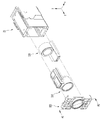
- FIG. 6A is a perspective view of a first lens assembly of the camera module according to the illustrated embodiment shown in FIG. 2.
- FIG. 6B is a view of some components removed from the first lens assembly of the camera module according to the embodiment shown in FIG. 6A;
- FIG. 7A is a perspective view of a second lens assembly of the camera module according to the illustrated embodiment shown in FIG. 2.
- FIG. 7B is a perspective view rotated 180 degrees about the optical axis of the second lens assembly of the camera module according to the embodiment shown in FIG. 8A.
- FIG. 8 is an enlarged view of a first region in a first lens assembly of the camera module according to the embodiment shown in FIG. 6A.
- FIGS. 9 is a cross-sectional view taken along line A1-A1 'of the camera module according to the embodiment shown in FIGS. 1 and 2;
- FIG. 10 is an enlarged view of a second area of the camera module according to the embodiment shown in FIG. 9;
- FIG. 11 is a detailed view of a second area of the camera module according to the embodiment shown in FIG.
- FIG. 12 shows a further embodiment of a second region of the camera module according to the embodiment shown in FIG. 10;
- FIG. 13A is another enlarged view of the third region of the camera module according to the embodiment shown in FIG. 12.
- FIG. 13A is another enlarged view of the third region of the camera module according to the embodiment shown in FIG. 12.
- FIG. 13B is an enlarged view of a fourth region of the camera module according to the embodiment shown in FIG. 13A.
- FIG. 1 is a perspective view of a camera module 100 according to an embodiment
- FIG. 2 is an exploded perspective view of the camera module 100 according to the embodiment shown in FIG. 1.
- the xz plane represents the ground
- the z axis represents the optical axis direction or parallel thereto
- the x axis is the direction perpendicular to the z axis in the ground (xz plane).
- the y-axis may mean perpendicular to the ground.
- the camera module 100 includes a first lens assembly 110, a second lens assembly 120, and a third lens assembly 130 in a predetermined base assembly 20.
- Various optical systems, such as, and the like, and a predetermined prism may be disposed on one side of the base assembly 20, for example, one side of the base assembly 20 in the direction of the third lens assembly 130.
- a predetermined image sensor part 25 may be disposed on the other side of the base assembly 20, for example, in the direction of the second lens assembly 120.
- the moving lens group may be three, four, or five or more.
- the first lens assembly 110 and the second lens assembly 120 may be a moving lens group, and the third lens assembly 130 may be fixed. It may be a lens group.
- the optical axis direction z may mean a direction that is the same as or parallel to the direction in which the lens groups are aligned.
- the camera module 100 includes a first lens assembly 110, a second lens assembly 120, and a third lens assembly 130 to perform a zooming function. can do.
- the third lens assembly 130 may perform a focator function to form parallel light at a specific position.
- the first lens assembly 110 may perform a variable function of reimaging the image formed in the third lens assembly 130 which is the condenser. Meanwhile, in the first lens assembly 110, the distance or the image distance with the subject is changed a lot, and thus the magnification change may be large.
- the first lens assembly 110 which is a changer, plays an important role in the focal length or magnification change of the optical system. can do.
- shops that are formed in the first lens assembly 110 which is a translator, may differ slightly depending on the location.
- the second lens assembly 120 may function as a position compensation for the image formed by the changer.
- the second lens assembly 120 is a compensator that serves to accurately image a shop formed in the first lens assembly 110, which is a translator, at a position of the actual image sensor unit 25 (see FIG. 5). (compensator) function can be performed.
- FIG. 3 is a perspective view of the third lens assembly 130 in the camera module according to the embodiment shown in FIG. 2.
- the third lens assembly 130 includes a third lens housing 132 on a predetermined lens cover 134 and a third lens group (3) on the third lens housing 132. 138 may be mounted.
- the third lens group 138 may include a single lens or a plurality of lenses.
- the lens cover 134 may be fitted with the base assembly 20 by fitting or adhesive.
- a hook 21p (see FIG. 4) may protrude from a side surface of the base assembly 20, and the lens cover 134 may have a hole (not shown) at a position corresponding to the hook 21p. Is formed, the hook 21p of the base assembly 20 is mounted in the hole of the lens cover 134 may be coupled to the lens cover 134 and the base assembly 20.
- the lens cover 134 may be stably coupled to the base assembly 20 by the adhesive.
- the lens cover 134 may be provided with a plurality of hole guides 132h to align with the optical axis, for example, the z-axis.
- FIG. 4 is a perspective view of the base assembly 20 in the camera module according to the embodiment shown in FIG. 2, and FIG. 5 is the base 21 removed from the base assembly 20 of the camera module shown in FIG. 3. Perspective view.
- the base assembly 20 includes a base 21, a circuit board 22, a yoke 23, a coil unit 24, a hall sensor 26, and an image sensor unit 25. And the like.
- the material of the base 21 may be formed of any one or more of plastic, glass-based epoxy, polycarbonate, metallic material, or a composite material.
- the third lens assembly 130, the first lens assembly 110, and the second lens assembly 120 may be sequentially disposed in the base 21 in parallel to the optical axis direction, and the base 20 may also be disposed.
- the circuit board 22 including the first circuit board 22a on one side and the second circuit board 22b on the other side may be disposed to be electrically connected to the lens driving units inside the base assembly 20.
- a predetermined prism (not shown) may be disposed on the third lens assembly 130 side, and the predetermined image sensor unit 25 may include the second lens assembly 120. ) May be disposed on the side.
- the first lens assembly 110, the second lens assembly 120, the third lens assembly 130, the prism, the image sensor unit 25, and the like may be classified as an optical system.
- the prism can convert the incident light into parallel light.
- the prism may change the incident light into parallel light by changing the optical path of the incident light to an optical axis (z-axis) parallel to the central axis of the lens group. Thereafter, the parallel light may pass through the third lens assembly 130, the first lens assembly 110, and the second lens assembly 120 to be incident on the image sensor unit 25 to capture an image.
- the prism may be an optical member having a triangular prism shape.
- Embodiments may also employ reflectors or reflectors instead of or in addition to prisms.
- the light passing through the lens group may be provided with an additional prism (not shown) to be picked up by the image sensor unit 25.
- the image sensor unit 25 may be disposed perpendicular to the optical axis direction of the parallel light.
- the image sensor unit 25 may include a solid-state imaging device disposed on a predetermined third circuit board (not shown).
- the image sensor unit 25 may include a Charge Coupled Device (CCD) image sensor or a Complementary Metal-Oxide-Semiconductor (CMOS) image sensor.
- CCD Charge Coupled Device
- CMOS Complementary Metal-Oxide-Semiconductor
- the base assembly 20 of the embodiment may include a predetermined coil part 24, a yoke 23, and a hall sensor 26 on the circuit board 22.
- the coil part 24 may include a first coil part 24a disposed on the first circuit board 22a and a second coil part 24b disposed on the second circuit board 22b.
- the first lens assembly 110 and the second lens assembly 120 may be driven by electromagnetic force.
- the embodiment may include a yoke 23 to control initial positions of the first lens assembly 110 and the second lens assembly 120.
- the embodiment may include a Hall sensor 26 to sense the positions of the first lens assembly 110 and the second lens assembly 120.
- the base assembly 20 of the embodiment may include a rail guide 28g inside the base 21, and in the embodiment, the first lens assembly 110, which is a moving lens group. ) And the second lens assembly 120 may be moved along the rail guide 28g in the optical axis direction.
- the rail guide 28g of the embodiment may include a first rail guide 28g1 formed at one side of the base 21 and a second rail guide 28g2 formed at the other side of the base.
- the first rail guide 28g1 may be formed in a singular or plural number, and may include, for example, a first-first rail guide 28g1a and a first-second rail guide 28g1b, but is not limited thereto. .
- the second rail guide 28g2 may be formed in the singular or plural, and may include, for example, a 2-1 rail guide 28g2a and a 2-2 rail guide 28g2a, but is not limited thereto. no.
- the rail guide 28g may be disposed in a direction parallel to the optical axis direction, and the rail guide 28g may be formed of the same or similar material as that of the base 21.
- the rail guide 28g may be formed of any one or more of plastic, glass-based epoxy, polycarbonate, metal, or a composite material, but is not limited thereto.
- the rail guide 28g supports the first lens assembly 110 or the second lens assembly 120 while zooming to prevent decentralization or lens tilt of the lens, thereby preventing image quality or resolution. There is a technical effect to improve the.
- first lens assembly 110 will be described with reference to FIGS. 6A and 6B, and the features of the second lens assembly 120 will also be described with reference to FIGS. 7A and 7B.
- FIG. 6A is a perspective view of the first lens assembly 110 of the camera module according to the embodiment shown in FIG. 2.
- FIG. 6B is a view in which some components are removed from the first lens assembly 110 of the camera module according to the embodiment shown in FIG. 6A.
- FIG. 6B is a camera module according to the embodiment shown in FIG. 6A. 1, the first group of balls 119, the first driving magnet 116, and the first sensing magnet 117 are removed from the first lens assembly 110.
- FIG. 7A is a perspective view of the second lens assembly 120 of the camera module according to the shown embodiment shown in FIG. 2, and FIG. 7B is a second lens assembly of the camera module according to the shown embodiment shown in FIG. 8A. It is a perspective view rotated 180 degrees with respect to the optical axis of 120.
- the first lens assembly 110 may include a first lens housing 112 and a first driver housing 114.
- the first lens group 112L may be disposed in the first lens housing 112.
- the first lens housing 112 may function as a barrel or a barrel, and the first lens group 112L may be mounted.
- the first lens group 112L may be a moving lens group, and may include a single lens or a plurality of lenses.
- the second lens assembly 120 may include a second lens housing 122 and a second driver housing 124.
- a second lens group 122L may be disposed in the second lens housing 122.
- the first drive unit housing 114 includes a first guide rail unit 118, a first group of balls 119, a first drive magnet 116, and a first sensing magnet ( 117 may be disposed.
- the first driving unit 114 may include a first recess 114r1 and a second recess 114r2 on one surface thereof, and a first driving magnet (1) in the first recess 114r1. 116 may be disposed, and a first sensing magnet 117 may be disposed in the second recess 114r2.
- the first driving magnet 116 may drive the first lens assembly 110 by electromagnetic force by interacting with the first coil part 24a disposed in the base assembly 20.
- the first sensing magnet 117 may interact with the hall sensor 26 disposed in the base assembly 20 to sense the position of the first lens assembly 110.
- the first driving magnet 116 and the first sensing magnet 117 may be a permanent magnet, but is not limited thereto.
- the magnetization method of the first driving magnet 116 in the camera module according to the embodiment may be a vertical magnetization method, but is not limited thereto.
- both the north pole and the south pole of the first driving magnet 116 may be magnetized to face the first coil unit 24a.
- the N pole and the S pole of the first driving magnet 116 may be disposed to correspond to the region in which the current flows in the first coil unit 24a, and the first driving magnet 116 and the first coil unit 24a may be disposed.
- the first lens assembly 110 may be driven by the electromagnetic force between the two elements, and the electromagnetic force may be controlled in proportion to the current applied to the first coil unit 24a.
- the first driver housing 114 may include one or more first guide rail portions 118 and a first group of balls 119 disposed on the first guide rail portions 118. Can be.
- the first guide rail unit 118 may be disposed on one side and the other side of the first driving unit housing 114, and the ball 119 of the first group is disposed in the first guide rail unit 118.
- the first lens assembly 110 may be moved parallel to the optical axis direction by rolling along the first guide rail unit 118.
- the ball 119 of the first group may include a plurality of balls, which will be described in more detail later with reference to FIG. 8.
- the second lens assembly 120 may include a second guide rail portion 128, a second group of balls 129, and a second driving magnet in the second driving unit housing 124. 126 and the second sensing magnet 127 may be disposed.
- an electromagnetic force between the second driving magnet 126 and the second coil part 24b may be generated to move the second lens assembly 120 horizontally to the optical axis.
- the second sensing magnet 127 may interact with the hall sensor 26 disposed in the base assembly 20 to sense the position of the second lens assembly 120.
- the second guide rail unit 128 may be disposed on one side and the other side of the second driving unit housing 124, respectively, and the ball 129 of the second group may be disposed in the second guide rail unit 128.
- the second lens assembly 120 may be moved parallel to the optical axis direction by rolling along the second guide rail portion 128, and the second guide rail portion (when moving the lens through zooming). 128 and the rolling drive through the ball 129 of the second group has a technical effect that can reduce the friction torque.
- FIG. 8 is an enlarged view of the first region B1 in the first lens assembly 110 of the camera module according to the embodiment shown in FIG. 6A.
- the first driving unit 114 may include one or more first guide rails 118 and a first group of balls 119 disposed on the first guide rails 118.
- the first group of balls 119 may include a first ball 119a and a second ball 119b having different diameters.
- the first driver housing 114 may include a first driving magnet 116 and a first sensing magnet 117.
- the first guide rail portion 118 is formed on a first guide body 118a, a first guide groove 118b formed in the first guide body 118a, and one side of the first guide body 118a.
- the first guide protrusion 118c may be included.
- the cross section of the first guide groove 118b in the first guide rail portion 118 may have a triangular shape, and accordingly, the second ball 119b has three technical points to minimize friction torque. have.
- the second ball 119b is in two-point contact with the first guide groove 118b having a triangular cross section, and one point is in contact with the recess 21R (see FIG. 10) of the base for a total of three points. In contact, friction torque can be minimized.
- the lens driving apparatus and the camera module including the same there is a technical effect of reducing friction torque when the lens moves through zooming in the camera module, thereby stably providing the first lens assembly.
- the 110 By guiding the 110, there is a technical effect of preventing lens decenter or lens tilt from occurring when the lens moves through the zooming in the camera module.
- FIG. 9 is a cross-sectional view taken along line A1-A1 'of the camera module according to the embodiment shown in FIGS. 1 and 2, and the first guide rail 118 and the first group of the first lens assembly 110 are shown. It is a sectional view in which the ball 119, the 2nd guide rail 128 of the 2nd lens assembly 120, and the 2nd group of balls 129 are shown together.
- the third lens assembly 130, the first lens assembly 110, and the second lens assembly 120 may be disposed parallel to the optical axis (z-axis) in the base 21.
- the image sensor unit 25 may be disposed in the direction of the two lens assembly 120.
- the configuration shown in FIG. 9 may employ the technical features of the above-described configuration, and further technical features will be described below with reference to FIG. 10.
- FIG. 10 is an enlarged view of a second area B2 associated with the first lens assembly 110 of the camera module according to the embodiment shown in FIG. 9.
- the first guide rail portion 118 of the first lens assembly 110 may include a first guide body 118a, a first guide groove 118b and the first guide formed in the first guide body 118a. 1 may include a first guide protrusion 118c formed on one side of the guide body 118a.
- the first lens assembly 110 may include a first group of balls 119 disposed on the first guide rail 118 to reduce friction torque when the lens moves through zooming.
- the base 21 may include a third guide recess 21R therein.
- the base 21 may include a third guide recess 21R in a region corresponding to the first guide groove 118b of the first guide rail unit 118.
- the lens assembly 110 may be driven by rolling.
- the first group of balls 119 may include balls of different diameters.
- the first group of balls 119 may include a first ball 119a having a first diameter D1 and a second ball 119b having a second diameter D2 larger than the first diameter D1.
- the second ball 119b may be provided in plural and disposed on both sides of the first ball 119a.
- One or more first balls 119a may be provided, for example, three but not limited thereto.
- the second ball 119b having a larger diameter is disposed outside the first ball 119a having a smaller diameter so that the first ball 119a is provided with the first guide rail 118 and the base 21.
- the first group of balls 119 is plural, and the number of the first balls 119a of the first diameter D1 is the number of the second balls 119b of the second diameter D2.
- the first group of balls 119 stably supports and moves the first lens assembly 110, thereby minimizing friction torque during zooming while decent or lens tilt of the lens. There is a complex technical effect that can prevent the occurrence of tilt and significantly improve image quality or resolution.
- the lens housing is moved within a predetermined stroke range by mechanical movement using a lens driving device for a zooming function. It may be stopped by the stopper and reversal of the zoom movement may be possible.
- an impact of a lens mounted on a lens housing may occur due to an impact of a lens housing and a stopper, and the lens decenter or lens tilt may be generated when the zoom movement is reversed. There is a technical problem occurring.
- the first lens assembly 110 is stopped by the first group of balls 119 disposed on the first guide rail 118, thereby providing the plurality of first By improving the shock absorbing force by the balls 119 of the group, there is a technical effect that can solve the problem of lens decentral or lens tilt occurs when the zoom movement is reversed.
- the first lens assembly 110 when the first lens assembly 110 moves away from the incident direction of light, the first lens assembly is disposed by the first group of balls 119 disposed on the first guide rail 118.
- the stop function of 110 improves the shock absorbing power by the plurality of first groups of balls 119, thereby reducing the impact in the lens housing when the zoom movement is reversed, thereby reducing the reliability of the magnet mounted in the lens housing.
- the first group of balls 119 are located within the first guide protrusion 118c of the first guide rail 118 and the guide sidewall 21RS of the inner side of the base 21.
- the first guide rail 118 may stop and the first lens assembly 110 may stop.
- the end 118ae of the first guide body 118a is spaced apart from the inner wall 21S of the base 21 by a first distance S1, so that the first lens assembly 110 and the base 21 itself.
- FIG. 11 is a detailed view of the second area B2 of the camera module according to the embodiment shown in FIG. 10.
- the length 119L in which the plurality of first groups of balls 119 are in contact with each other may be 1/2 or more of the length 118L of the first guide rail 118.
- the first group of balls 119 is plural, and the first group of balls 119 stably supports and moves the first lens assembly 110 to friction during zooming. There is a technical effect to improve image quality or resolution by minimizing torque and preventing lens decent or lens tilt.
- FIG. 12 is a view of a further embodiment of the second area B2 of the camera module according to the embodiment shown in FIG. 10.
- the first shock absorbing layer 118d may be further disposed inside the first guide protrusion 118c of the first guide rail 118.
- the plurality of first groups of balls 119 are provided. Improving the shock absorbing power and minimizing the impact between the first group of balls 119 and the first guide protrusion 118c by the first shock absorbing layer 118d, so that the lens decenter or lens at the time of inversion of the zoom motion There is a technical effect that can effectively solve the problem that the tilt (tilt) occurs.
- the first shock absorbing layer 118d may be formed of a material having a higher shock absorbency than the material of the first guide protrusion 118c.
- the first shock absorbing layer 118d may be formed of a shock absorbing material such as a soft metal such as urethane material, Al, an elastic material, or a fiber material, but is not limited thereto.
- FIG. 13A is an enlarged view of another embodiment of the third area B3 of the camera module according to the embodiment shown in FIG. 12, and FIG. 13B is a fourth view of the camera module according to the embodiment shown in FIG. 13A. It is an enlarged view of the area B4.
- the sidewalls of the first shock absorbing layer 118d are recessed to correspond to the outer shape of the balls 119 of the first group so as to correspond to the outer shape of the balls 119 of the first group.
- the plurality of first groups of balls 119 are provided.
- the impact between the first group of balls 119 and the first guide protrusion 118c is further minimized by the first shock absorbing layer 118d, so that the lens decenter or the lens may be reduced when the zoom movement is reversed.
- the lens tilt tilt
- the lens driving apparatus and the camera module including the same there is a technical effect of reducing friction torque when the lens moves through zooming in the camera module.
- the embodiment may be applied to a mobile terminal such as a mobile phone, a notebook, a drone, a vehicle, and the like.
- the camera module according to the embodiment may be embedded in a portable device such as a smartphone, a tablet PC, a notebook computer, and the like.
- the camera module according to the embodiment may perform an autofocus function that automatically adjusts the distance between the image sensor and the lens to align the focal length of the lens.
Landscapes
- Physics & Mathematics (AREA)
- General Physics & Mathematics (AREA)
- Optics & Photonics (AREA)
- Lens Barrels (AREA)
- Studio Devices (AREA)
Abstract
Un mode de réalisation de la présente invention concerne un dispositif d'entraînement de lentille et un module d'appareil de prise de vue le comprenant. Le dispositif d'entraînement de lentille selon un mode de réalisation peut comprendre : un ensemble de base; et un premier ensemble de lentille comprenant un premier boîtier de lentille et un premier boîtier de partie d'entraînement de façon à être disposé à l'intérieur de l'ensemble de base et à se déplacer parallèlement à un axe optique prédéterminé. Le premier boîtier de partie d'entraînement peut comprendre une ou plusieurs premières parties de rail de guidage au niveau d'un côté de celui-ci et un premier groupe de billes disposées au niveau de la première partie de rail de guidage. La première partie de rail de guidage peut comprendre : un premier corps de guidage; une première rainure de guidage formée sur le premier corps de guidage; et une première partie saillante de guidage formée sur un côté du premier corps de guidage.
Priority Applications (2)
| Application Number | Priority Date | Filing Date | Title |
|---|---|---|---|
| US17/268,842 US12313897B2 (en) | 2018-08-16 | 2019-08-14 | Lens driving device and camera module including same |
| CN201980060641.7A CN112740102B (zh) | 2018-08-16 | 2019-08-14 | 透镜驱动装置和包括透镜驱动装置的相机模块 |
Applications Claiming Priority (2)
| Application Number | Priority Date | Filing Date | Title |
|---|---|---|---|
| KR1020180095508A KR102585027B1 (ko) | 2018-08-16 | 2018-08-16 | 렌즈 구동장치 및 이를 포함하는 카메라 모듈 |
| KR10-2018-0095508 | 2018-08-16 |
Publications (1)
| Publication Number | Publication Date |
|---|---|
| WO2020036450A1 true WO2020036450A1 (fr) | 2020-02-20 |
Family
ID=69525696
Family Applications (1)
| Application Number | Title | Priority Date | Filing Date |
|---|---|---|---|
| PCT/KR2019/010397 Ceased WO2020036450A1 (fr) | 2018-08-16 | 2019-08-14 | Dispositif d'entraînement de lentille et module de prise de vues le comprenant |
Country Status (4)
| Country | Link |
|---|---|
| US (1) | US12313897B2 (fr) |
| KR (1) | KR102585027B1 (fr) |
| CN (1) | CN112740102B (fr) |
| WO (1) | WO2020036450A1 (fr) |
Cited By (1)
| Publication number | Priority date | Publication date | Assignee | Title |
|---|---|---|---|---|
| EP4398463A3 (fr) * | 2021-01-25 | 2025-11-26 | Hand Held Products, Inc. | Ensembles à foyer variable et appareils ayant des billes à roulement croisé |
Families Citing this family (15)
| Publication number | Priority date | Publication date | Assignee | Title |
|---|---|---|---|---|
| KR102723559B1 (ko) * | 2018-08-02 | 2024-10-30 | 엘지이노텍 주식회사 | 렌즈 구동장치 및 이를 포함하는 카메라 모듈 |
| US11556047B2 (en) * | 2019-08-16 | 2023-01-17 | Tdk Taiwan Corp. | Optical member driving mechanism including matrix structure that corresponds to noise |
| US11428894B2 (en) | 2020-02-04 | 2022-08-30 | Hand Held Products, Inc. | Discrete variable focus assemblies and apparatuses |
| KR20210137719A (ko) * | 2020-05-11 | 2021-11-18 | 엘지이노텍 주식회사 | 카메라 엑추에이터 및 이를 포함하는 카메라 장치 |
| EP4198625B1 (fr) | 2020-08-11 | 2026-04-29 | LG Innotek Co., Ltd. | Actionneur de caméra |
| US11815736B2 (en) * | 2020-09-15 | 2023-11-14 | Tdk Taiwan Corp. | Optical element driving mechanism |
| KR102696885B1 (ko) | 2020-09-28 | 2024-08-20 | 자화전자(주) | 줌 구동 액추에이터 및 줌 구동을 위한 위치제어방법 |
| KR102890453B1 (ko) * | 2020-10-21 | 2025-11-25 | 엘지이노텍 주식회사 | 카메라 액추에이터 및 이를 포함하는 카메라 모듈 |
| WO2022086158A1 (fr) | 2020-10-21 | 2022-04-28 | 엘지이노텍 주식회사 | Actionneur de caméra et module de caméra le comprenant |
| CN114859498A (zh) * | 2021-02-05 | 2022-08-05 | 信泰光学(深圳)有限公司 | 变焦镜头 |
| KR20230022599A (ko) * | 2021-08-09 | 2023-02-16 | 엘지이노텍 주식회사 | 카메라 엑추에이터 및 이를 포함하는 카메라 장치 |
| US20230070594A1 (en) * | 2021-09-03 | 2023-03-09 | Hand Held Products, Inc. | Lens unit of an imaging assembly |
| US12117598B2 (en) | 2022-03-11 | 2024-10-15 | Hand Held Products, Inc. | Variable focusing lens apparatus |
| US12197034B2 (en) | 2023-02-28 | 2025-01-14 | Hand Held Products, Inc. | Bi-directional closed loop multi-focus-position lens apparatus and method |
| KR20260024818A (ko) * | 2024-08-14 | 2026-02-23 | 엘지이노텍 주식회사 | 렌즈구동장치, 카메라 장치 및 광학기기 |
Citations (5)
| Publication number | Priority date | Publication date | Assignee | Title |
|---|---|---|---|---|
| KR100274384B1 (ko) * | 1996-01-26 | 2001-03-02 | 마츠모토 도루 | 카메라용 가요성프린트회로기판하우징구조체 |
| KR100920609B1 (ko) * | 2008-11-27 | 2009-10-08 | 삼성전기주식회사 | 카메라 모듈용 액추에이터, 이의 제어방법 및 이를 포함하는 카메라 모듈 |
| KR20160024319A (ko) * | 2014-08-25 | 2016-03-04 | 자화전자(주) | 카메라 렌즈 모듈 |
| WO2017135789A1 (fr) * | 2016-02-04 | 2017-08-10 | 마이크로엑츄에이터(주) | Ensemble objectif de caméra |
| KR20170130271A (ko) * | 2016-05-18 | 2017-11-28 | 삼성전기주식회사 | 카메라 모듈 |
Family Cites Families (39)
| Publication number | Priority date | Publication date | Assignee | Title |
|---|---|---|---|---|
| JPS58111003A (ja) * | 1981-12-25 | 1983-07-01 | Canon Inc | ズ−ムレンズ構体 |
| US5842057A (en) | 1996-01-26 | 1998-11-24 | Asahi Kogaki Kogo Kabushiki Kaisha | Camera with lens barrier apparatus |
| US6134057A (en) * | 1997-09-17 | 2000-10-17 | Minolta Co., Ltd. | Drive and guide mechanism and apparatus using the mechanism |
| JP2000019376A (ja) * | 1998-07-02 | 2000-01-21 | Minolta Co Ltd | 駆動装置 |
| JP2007271889A (ja) * | 2006-03-31 | 2007-10-18 | Citizen Miyota Co Ltd | 固体撮像装置 |
| JP2009229781A (ja) * | 2008-03-24 | 2009-10-08 | Konica Minolta Opto Inc | 駆動機構および駆動装置 |
| KR101643771B1 (ko) * | 2008-10-30 | 2016-07-29 | 삼성전자주식회사 | 카메라 렌즈 어셈블리 |
| KR101041473B1 (ko) * | 2009-09-04 | 2011-06-16 | 자화전자(주) | 카메라 렌즈 어셈블리 |
| KR20130081398A (ko) * | 2012-01-09 | 2013-07-17 | 자화전자(주) | 카메라 렌즈 어셈블리 |
| KR101314652B1 (ko) | 2012-03-30 | 2013-10-07 | 자화전자(주) | 카메라 모듈 구동 제어 장치 및 방법 |
| KR20140036448A (ko) * | 2012-09-14 | 2014-03-26 | 쓰리에이치비젼주식회사 | 카메라 렌즈 모듈 |
| CN203217151U (zh) * | 2013-03-07 | 2013-09-25 | 华宏新技股份有限公司 | 镜头致动装置 |
| US9618768B2 (en) * | 2013-05-29 | 2017-04-11 | Lg Innotek Co., Ltd. | Lens driving device |
| US10348968B2 (en) | 2013-10-09 | 2019-07-09 | Sharp Kabushiki Kaisha | Method for producing camera module |
| JP6231416B2 (ja) * | 2014-03-20 | 2017-11-15 | Hoya株式会社 | 撮像装置 |
| US9578242B2 (en) | 2014-04-11 | 2017-02-21 | Samsung Electro-Mechanics Co., Ltd. | Camera module |
| CN107111212B (zh) * | 2014-11-12 | 2019-11-12 | 艾斯科技公司 | 摄像头模块自动对焦致动器及其控制方法 |
| US10634867B2 (en) * | 2014-11-28 | 2020-04-28 | Samsung Electro-Mechanics Co., Ltd. | Camera module |
| KR102392579B1 (ko) | 2015-01-12 | 2022-05-02 | 엘지이노텍 주식회사 | 렌즈 구동장치 및 이를 포함하는 카메라 모듈 |
| KR20160103437A (ko) * | 2015-02-24 | 2016-09-01 | 삼성전기주식회사 | 액추에이터 및 이를 포함하는 카메라 모듈 |
| KR102494346B1 (ko) * | 2015-04-10 | 2023-02-01 | 삼성전기주식회사 | 렌즈 구동 장치 및 이를 포함하는 카메라 모듈 |
| CN106291862A (zh) | 2015-06-23 | 2017-01-04 | 三星电机株式会社 | 相机模块 |
| US9995904B2 (en) | 2015-08-14 | 2018-06-12 | Samsung Electro-Mechanics Co., Ltd. | Actuator driving device and camera module including the same |
| KR102013190B1 (ko) | 2015-09-25 | 2019-08-22 | 자화전자(주) | 카메라 렌즈 모듈 |
| KR101896962B1 (ko) | 2016-02-04 | 2018-09-12 | 마이크로엑츄에이터(주) | 카메라 렌즈 조립체 |
| JP6617395B2 (ja) * | 2016-02-17 | 2019-12-11 | 新シコー科技株式会社 | レンズ駆動装置、カメラ装置及び電子機器 |
| KR101704498B1 (ko) * | 2016-03-10 | 2017-02-09 | 자화전자(주) | 3위치 지지구조의 자동초점 조절장치 |
| KR102367554B1 (ko) * | 2016-07-26 | 2022-02-25 | 자화전자(주) | 줌렌즈용 구동장치 |
| US11163211B2 (en) * | 2016-10-04 | 2021-11-02 | Samsung Electro-Mechanics Co., Ltd. | Camera module actuator |
| KR101953135B1 (ko) * | 2016-12-20 | 2019-02-28 | 자화전자(주) | 비대칭 지지 구조의 자동초점 조절장치 |
| JP2018120072A (ja) * | 2017-01-25 | 2018-08-02 | シーエム・テクノロジー株式会社 | レンズ駆動装置 |
| KR102072811B1 (ko) * | 2017-06-16 | 2020-03-02 | 삼성전기주식회사 | 카메라 모듈 |
| KR20170131320A (ko) * | 2017-11-20 | 2017-11-29 | 삼성전기주식회사 | 카메라 모듈 |
| KR102723559B1 (ko) * | 2018-08-02 | 2024-10-30 | 엘지이노텍 주식회사 | 렌즈 구동장치 및 이를 포함하는 카메라 모듈 |
| KR102207901B1 (ko) * | 2018-08-07 | 2021-01-26 | 삼성전기주식회사 | 카메라 모듈 |
| KR102705493B1 (ko) * | 2018-10-11 | 2024-09-11 | 엘지이노텍 주식회사 | 카메라 액추에이터, 및 이를 포함하는 카메라 모듈 |
| KR102233576B1 (ko) * | 2018-10-17 | 2021-03-30 | 자화전자(주) | 다극 마그네트 구조가 장착된 액추에이터 |
| CN114174915B (zh) * | 2019-07-26 | 2024-04-12 | Lg伊诺特有限公司 | 相机模块 |
| JP7355643B2 (ja) | 2019-12-24 | 2023-10-03 | 未来工業株式会社 | 配線器具取付体 |
-
2018
- 2018-08-16 KR KR1020180095508A patent/KR102585027B1/ko active Active
-
2019
- 2019-08-14 CN CN201980060641.7A patent/CN112740102B/zh active Active
- 2019-08-14 WO PCT/KR2019/010397 patent/WO2020036450A1/fr not_active Ceased
- 2019-08-14 US US17/268,842 patent/US12313897B2/en active Active
Patent Citations (5)
| Publication number | Priority date | Publication date | Assignee | Title |
|---|---|---|---|---|
| KR100274384B1 (ko) * | 1996-01-26 | 2001-03-02 | 마츠모토 도루 | 카메라용 가요성프린트회로기판하우징구조체 |
| KR100920609B1 (ko) * | 2008-11-27 | 2009-10-08 | 삼성전기주식회사 | 카메라 모듈용 액추에이터, 이의 제어방법 및 이를 포함하는 카메라 모듈 |
| KR20160024319A (ko) * | 2014-08-25 | 2016-03-04 | 자화전자(주) | 카메라 렌즈 모듈 |
| WO2017135789A1 (fr) * | 2016-02-04 | 2017-08-10 | 마이크로엑츄에이터(주) | Ensemble objectif de caméra |
| KR20170130271A (ko) * | 2016-05-18 | 2017-11-28 | 삼성전기주식회사 | 카메라 모듈 |
Cited By (1)
| Publication number | Priority date | Publication date | Assignee | Title |
|---|---|---|---|---|
| EP4398463A3 (fr) * | 2021-01-25 | 2025-11-26 | Hand Held Products, Inc. | Ensembles à foyer variable et appareils ayant des billes à roulement croisé |
Also Published As
| Publication number | Publication date |
|---|---|
| KR20200020147A (ko) | 2020-02-26 |
| US12313897B2 (en) | 2025-05-27 |
| US20210231904A1 (en) | 2021-07-29 |
| CN112740102A (zh) | 2021-04-30 |
| CN112740102B (zh) | 2023-02-10 |
| KR102585027B1 (ko) | 2023-10-06 |
Similar Documents
| Publication | Publication Date | Title |
|---|---|---|
| WO2020036450A1 (fr) | Dispositif d'entraînement de lentille et module de prise de vues le comprenant | |
| WO2020027588A1 (fr) | Dispositif d'entraînement de lentille et module de prise de vues incluant ce dispositif d'entraînement | |
| WO2019164296A1 (fr) | Module de caméra | |
| WO2020080906A1 (fr) | Actionneur de caméra et module de caméra le comprenant | |
| WO2019168342A1 (fr) | Dispositif d'entraînement de lentille | |
| WO2017188771A1 (fr) | Mécanisme d'entraînement de lentille, module d'appareil de prise de vues, et dispositif optique | |
| WO2018056770A1 (fr) | Barillet de lentille de caméra, module de caméra et dispositif optique | |
| WO2022124850A1 (fr) | Système optique et module de caméra le comprenant | |
| WO2019151700A1 (fr) | Module d'appareil photo | |
| WO2020122594A1 (fr) | Ensemble lentilles et module de caméra le comprenant | |
| WO2019199130A1 (fr) | Dispositif d'entraînement de lentille et module de prise de vues incluant ce dispositif d'entraînement | |
| WO2021246708A1 (fr) | Actionneur pour module de caméra dioptrique et module de caméra le comprenant | |
| WO2020251203A1 (fr) | Appareil d'attaque d'ensemble lentille et module de caméra le comprenant | |
| WO2022245054A1 (fr) | Dispositif de caméra | |
| WO2022059949A1 (fr) | Dispositif de caméra et instrument optique | |
| WO2021020738A2 (fr) | Module de caméra | |
| WO2020036449A1 (fr) | Dispositif de prévention de tremblement d'image comprenant un prisme, et module de caméra le comprenant | |
| WO2024025071A1 (fr) | Dispositif d'entraînement de lentille, dispositif de caméra et instrument optique | |
| WO2021054725A1 (fr) | Module de caméra | |
| WO2025053440A1 (fr) | Dispositif d'entraînement de lentille, dispositif de caméra et instrument optique | |
| WO2025178379A1 (fr) | Actionneur de caméra et module de caméra le comprenant | |
| WO2025198253A1 (fr) | Module de caméra comprenant un ensemble lentille | |
| WO2024117849A1 (fr) | Actionneur de caméra | |
| WO2025029103A1 (fr) | Dispositif d'entraînement de lentille, dispositif de caméra et instrument optique | |
| WO2024155045A1 (fr) | Actionneur de caméra et module de caméra le comprenant |
Legal Events
| Date | Code | Title | Description |
|---|---|---|---|
| 121 | Ep: the epo has been informed by wipo that ep was designated in this application |
Ref document number: 19849617 Country of ref document: EP Kind code of ref document: A1 |
|
| NENP | Non-entry into the national phase |
Ref country code: DE |
|
| 122 | Ep: pct application non-entry in european phase |
Ref document number: 19849617 Country of ref document: EP Kind code of ref document: A1 |
|
| WWG | Wipo information: grant in national office |
Ref document number: 17268842 Country of ref document: US |