WO2020037547A1 - Procédé et dispositif de maintenance intelligente pour réseau de fibres optiques - Google Patents
Procédé et dispositif de maintenance intelligente pour réseau de fibres optiques Download PDFInfo
- Publication number
- WO2020037547A1 WO2020037547A1 PCT/CN2018/101730 CN2018101730W WO2020037547A1 WO 2020037547 A1 WO2020037547 A1 WO 2020037547A1 CN 2018101730 W CN2018101730 W CN 2018101730W WO 2020037547 A1 WO2020037547 A1 WO 2020037547A1
- Authority
- WO
- WIPO (PCT)
- Prior art keywords
- information
- optical port
- optical
- optical fiber
- port
- Prior art date
- Legal status (The legal status is an assumption and is not a legal conclusion. Google has not performed a legal analysis and makes no representation as to the accuracy of the status listed.)
- Ceased
Links
Images

Classifications
-
- G—PHYSICS
- G06—COMPUTING OR CALCULATING; COUNTING
- G06K—GRAPHICAL DATA READING; PRESENTATION OF DATA; RECORD CARRIERS; HANDLING RECORD CARRIERS
- G06K17/00—Methods or arrangements for effecting co-operative working between equipments covered by two or more of main groups G06K1/00 - G06K15/00, e.g. automatic card files incorporating conveying and reading operations
Definitions
- the present invention relates to a maintenance method and device for an optical fiber communication system, and more particularly to an intelligent maintenance method and device for an optical fiber network.
- Paper labels are bundled on the optical fiber connector.
- the connector's business type, optical path code, local optical port position, opposite optical port position, and Information such as length, paper labels have become the basis for differentiating and judging lines for optical fiber line management, and have become an indispensable part of fiber jump management in computer rooms. How to realize the rapid entry and identification of paper labels, and the use of information related to computer room information management. Success or failure.
- the paper label on the optical port in the telecommunications room has two types: printing and handwriting. Because the on-site optical port routing is manually jumped, a paper label is made, and then it is recorded and delivered by a special person to upload the resource management system. However, the situation on the site is complicated, the construction staff writes irregularly, and the uploaded data cannot be identified. After years of deposition, the inconsistency rate between the on-site optical port routing information and the routing information of the resource management system is as high as 40%. Network troubleshooting requires familiarity with the computer room. The operation of construction personnel and the long troubleshooting time have caused serious conflicts with increasing network maintenance requirements.
- the technical problem to be solved by the present invention is to provide a method and a device for intelligent maintenance of an optical fiber network in view of the foregoing defects of the prior art.
- the present invention provides an intelligent maintenance method for an optical fiber network, which includes the following steps:
- the information collection of the optical fiber routing port takes pictures of the paper labels on the connectors of all the optical fiber routing ports in the computer room to collect pictures; processes each of the pictures to generate picture information, and combines the information corresponding to the picture information.
- the smart terminal performs photographing processing on the paper label to be identified on the connector of any of the optical fiber routing ports to generate image information to be identified, and uploads the image information to be identified.
- the background server or cloud server searches and compares the picture information in the optical port information tag database; if the target picture information that is consistent with the picture information to be identified is found, the corresponding one of the target picture information is retrieved. Full information on the paper label and activate the corresponding optical port coding; and
- the information of the optical fiber routing port is supplemented or corrected. If the consistent target picture information of the picture information to be identified is not found, the position coordinates of the paper label to be identified are input to generate an optical port code, and then the The information of the optical fiber routing port corresponding to the identified paper label is combined with the to-be-recognized picture information to generate new optical port information, and the new optical port information is uploaded to the background server or cloud server to update the optical port information label. database.
- the foregoing intelligent maintenance method for an optical fiber network further includes the following steps:
- S400 Locate the paper label. Enter the optical port code of the paper label to be searched on the smart terminal, or the optical port related content information, such as service name, leased line number, optical path code, etc., and upload it to the background server or cloud.
- Server the background server or cloud server finds the optical fiber distribution frame where the optical port code is located through the optical port information tag database, and sends an instruction to cause the optical port locator on the optical fiber distribution frame to prompt,
- the display of the optical port locator displays the horizontal and vertical coordinates of the position of the paper label corresponding to the optical port code, or the position of the optical port is displayed by a reminder lamp connected to each optical port through the optical port locator.
- the paper label is positioned quickly.
- the searching and comparing the picture information to be identified in the step S200 further includes:
- S201 Determine the glyphs in the picture information to be identified, and distinguish them into a printed body, a handwritten body, or a mixed body;
- step S204 If it is a mixed body, first use the method of step S202 to identify the printed body, and then use the method of step S203 to identify the handwritten body for content recognition, and perform a search and comparison with the picture information in the optical port information tag database .
- the screening identification includes word number identification, line number identification, and overprint identification
- the overprint identification includes:
- Setting the picture information to be identified as a sub-tag setting the picture information in the optical port information tag database as a parent tag, scaling and rotating the sub-tag and the parent tag to be the same size, and calculating the sub-tags respectively The total pixel points of the tag and the parent tag. If the total pixel points of the child tag and the parent tag are the same, the child tag and the parent tag are the same tag.
- the trajectory identification is to process the handwriting on the picture information to be identified as a single pixel, and perform trajectory comparison.
- the method when the paper label is photographed, the method further includes marking at least two positioning points on the paper label.
- the method when processing the picture to generate picture information, the method further includes performing boundary correction and enhanced sharpening on the picture.
- the information of the optical fiber routing port includes:
- Optical port coding optical path coding, leased line number, service name, distance between upstream and downstream optical ports, connection point line and end face loss, loss change history, jumper and change records, operator information, location address, connected device information, and History records, time node information, routing information, and fault records.
- the address information includes, but is not limited to, GPS address information
- the background server or cloud server uses the address information to extract a location and the target information in the optical port information tag database. Compare the picture information with the similar picture information, find the picture information that is consistent with the picture information to be recognized, and download all the information of the paper label corresponding to the consistent picture information to the smart terminal.
- the foregoing intelligent maintenance method for an optical fiber network further includes the following steps:
- S500 Associate the optical port information corresponding to the optical port code with other optical port information in the optical port information label database according to the content of the optical routing port on-site identification, supplement or correction, to generate a fiber line routing topology map.
- an intelligent maintenance device for an optical fiber network which includes:
- An intelligent terminal is used for information collection, identification, and supplementary correction of fiber optic routing ports. It collects pictures by taking pictures of paper labels on the connectors of all fiber optic routing ports in the computer room; processing each of these pictures to generate picture information, and Combining optical fiber routing port information corresponding to the picture information to generate optical port information; and
- a background server or a cloud server connected to the smart terminal, and configured to receive the optical port information uploaded by the smart terminal and generate an optical port information tag database;
- the background server or cloud server is further configured to receive the to-be-recognized picture information uploaded by the smart terminal, perform a search and comparison with the picture information in the optical port information tag database, and find the picture information that is consistent with the to-be-recognized picture information. After the picture information, retrieve all the information of the paper label corresponding to the consistent picture information and activate the corresponding optical port coding; if the consistent picture information of the picture information to be identified is not found, pass the The smart terminal inputs the position coordinates of the paper label to be identified to generate an optical port code, and enters the information of the optical fiber routing port corresponding to the paper label to be identified, and combines the image information to be identified to generate new optical port information. The smart terminal uploads the new optical port information to the background server or cloud server to join the optical port information tag database.
- optical port information in the database in addition to textual representation, adds image record information and historical record information storage;
- optical port locator and optical port locator on the distribution frame where the paper label is located can be activated in the reverse direction through the optical port code, and the corresponding paper label can be quickly found through sound and light prompts.
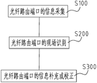
- FIG. 1 is a flowchart of an embodiment of the present invention
- FIG. 2 is a schematic diagram of a working process according to another embodiment of the present invention.
- the paper label is not associated with background information such as the optical port code, connection point line and end-face loss information, location address, and connected equipment, and there is no historical information record of the optical port;
- FIG. 1 is a flowchart of an embodiment of the present invention.
- the intelligent maintenance method for an optical fiber network of the present invention is applicable to the maintenance and management of an optical fiber distribution frame, an optical port at an optical fiber device, an ONU at a user end, and an outdoor optical fiber transfer box, and includes the following steps:
- Step S100 Collect information of the optical fiber routing port, and take pictures of the paper labels on the connectors of all the optical fiber routing ports in the computer room through smart terminals to collect pictures; process each of the pictures to generate picture information, and merge the corresponding picture information.
- the optical port information is generated after the information of the optical fiber routing port, and the optical port information is uploaded to a background server or a cloud server to generate an optical port information label database.
- the information of the optical fiber routing port includes: optical port coding, optical path coding, dedicated line number, service name, distance between upstream and downstream optical ports, connection point line and end face loss, loss change history, jumper and change records, Operator information, location address information, connected device information and history, time node information, routing information, fault records.
- Step S200 On-site identification of the optical fiber routing port.
- the smart terminal performs photographing processing on the paper label to be identified on the connector of any of the optical fiber routing ports, generates image information to be identified, and uploads the image information to be identified.
- the background server or the cloud server searches and compares the picture information in the optical port information tag database; if the target picture information that is consistent with the picture information to be identified is found, the corresponding picture corresponding to the target picture information is retrieved.
- the information tag database extracts the picture information that is close to the picture information to be identified and compares, finds the target picture information that is consistent with the picture information to be identified, and compares the paper corresponding to the target picture information. Download all the information of the quality label to the smart terminal.
- the situation of the near target picture information can also be manually identified and selected; and
- Step S300 The information of the optical fiber routing port is supplemented or corrected. If the consistent target picture information of the picture information to be identified is not found, the position coordinates of the paper label to be identified are input to generate an optical port code, and entered into the The information of the optical fiber routing port corresponding to the paper label to be identified is combined with the to-be-identified picture information to generate new optical port information, and the loss loss parameter information and personnel time information can also be entered at the same time, and the new optical port information is uploaded to the office.
- the background server or cloud server to update the optical port information tag database.
- the invention may further include the following steps:
- Step S400 positioning of the paper label, input the optical port code of the paper label to be searched on the smart terminal, or the optical port related content information, such as service name, dedicated line number, optical path code, etc., and upload it to the background server or A cloud server, the background server or the cloud server finds the optical fiber distribution frame where the optical port code is located through the optical port information label database, and sends an instruction to prompt the optical port locator on the optical fiber distribution frame,
- the display screen of the optical port locator displays the horizontal and vertical coordinates of the position of the paper label corresponding to the optical port code, or the position of the optical port is displayed by a reminder lamp connected to each optical port through the optical port locator. Quick positioning of the paper label.
- Step S500 Associate the optical port information corresponding to the optical port code with other optical port information in the optical port information label database according to the content of the optical routing port on-site identification, supplement, or correction to generate a fiber line routing topology map.
- the present invention can be divided into two steps of entry and identification: the entry stage, inputting the optical port code, and searching in the optical port information tag database of the server. If there is no record, the paper photo is taken in step S100, and additional information in steps S200-S300 Upload the database, the server judges that there are no similar tags, and counts them into the optical port information tag database after confirmation. In the recognition phase, directly take pictures and upload. Steps S200-S300 start the database search. If there is, the corresponding optical port information is downloaded. If not, the operator is prompted to enter new optical port information and update the optical port information label database. When entering in large quantities, there is a display in the APP and a visual click operation. When the server needs to store all the optical port information in the database, it needs to identify the tags entered in the comparison database to avoid repeated errors and ensure that the database information is correct.
- the paper label is entered, there is a cabinet label on the cabinet. At this time, you only need to scan the code, enter the cabinet page of the APP, and click the optical port of the label to be collected. After entering, you can see the corresponding paper label.
- the optical port information is entered if there is no optical port information.
- the server recognizes the paper label and determines whether there is a conflict with other labels. If not, it stores the optical port information corresponding to the paper label and updates the optical port paper label information. Database; if there is, it will form a conflict event and ask the maintenance personnel to handle it; if there is optical port information, you can see the paper label picture downloaded from the server's optical port paper label information database and compare it with the on-site label.
- optical port information will cause a conflict event and it is requested to be handled by the maintenance personnel; if there is no such optical port information, the optical port information of the paper label is updated.
- FIG. 2 is a schematic diagram of a working process according to another embodiment of the present invention.
- the searching and comparing the picture information to be identified in step S200 further includes:
- Step S201 Determine the glyphs in the picture information to be identified, and distinguish them into a printed body, a handwritten body, or a mixed body;
- Step S202 If it is a print, the content can be directly identified by OCR and compared with the picture information in the optical port information in the optical port information tag database, which is an identification that is available on Facebook Cloud or Tencent Cloud. Function, can increase manual comparison confirmation;
- Step S203 If it is handwritten, there will be a lot of errors in general cloud recognition. The reason is that the writing is too scribbled and not standardized. Then you need to identify the content through track recognition, overprint recognition, or screening recognition, and compare with the optical port information label database.
- the optical port information in the optical port information is searched and compared; wherein the screening recognition includes word number recognition, line number recognition, and overprint recognition, and the overprint recognition includes: setting the picture information to be identified as a sub-picture.
- Label set the picture information in the optical port information in the optical port information tag database as a parent label, and scale and rotate the child label to be the same size as the parent label, and calculate the child label and the parent label, respectively If the total pixel points of the child tag and the parent tag are the same or similar, then the child tag is the same tag as the parent tag; the track identification is based on a single handwriting on the picture information to be identified. Pixel processing and track comparison;
- Step S204 If it is a mixed body, first use the method of step S202 to identify the printed body, and perform a search and comparison with the picture information in the optical port information tag database. If the unique target picture information is found, call and All the information of the paper label corresponding to the target picture information and activate the corresponding optical port coding; if the unique target picture information cannot be determined, then the method of step S203 is used to identify the handwriting and then identify the content, and communicate with the optical port Find and compare the picture information in the information tag database.
- the method when taking a photo of the paper label, it also includes marking at least two positioning points on the paper label to facilitate positioning during identification, for example, the upper-left corner is the outermost, and the lower-right corner is the outermost, two-point positioning, and other points. Look at the deviation, so that these two points can be identified more accurately.
- the method further includes performing boundary correction and enhanced sharpening on the picture.
- the present invention also provides an optical fiber network intelligent maintenance device adopting the above-mentioned intelligent maintenance method, including:
- Smart terminal which can be, for example, a full-fiber optical fiber detector, or a mobile phone or a pad that can be installed with an APP that implements the above-mentioned intelligent maintenance method.
- the smart terminal is used for information collection, identification, and supplementary correction of fiber routing ports.
- the paper labels on the connectors of all fiber optic routing ports in the equipment room take pictures to collect pictures; process each of the pictures to generate picture information, and merge the information of the fiber optic routing ports corresponding to the picture information to generate optical port information ;as well as
- a background server or a cloud server connected to the smart terminal, and configured to receive the optical port information uploaded by the smart terminal and generate an optical port information tag database;
- the background server or cloud server is further configured to receive the to-be-recognized picture information uploaded by the smart terminal, perform a search and comparison with the picture information in the optical port information tag database, and find the picture information that is consistent with the to-be-recognized picture information. After the picture information, retrieve all the information of the paper label corresponding to the consistent picture information and activate the corresponding optical port coding; if the consistent picture information of the picture information to be identified is not found, pass the The smart terminal inputs the position coordinates of the paper label to be identified to generate an optical port code, and enters the information of the optical fiber routing port corresponding to the paper label to be identified, and combines the image information to be identified to generate new optical port information. The smart terminal uploads the new optical port information to the background server or cloud server to update the optical port information tag database.
- a paper tag on a fiber optic routing port (optical port) connector can be photographed and collected on a smart terminal, a picture of the paper tag can be selected and processed, and then the processed picture on the smart terminal can be processed.
- Text format, with additional address information including but not limited to GPS address information
- the cloud server intelligently identifies the picture, and the background information of the picture such as the optical port code, connection point line and end face loss information, location address (Including but not limited to GPS), connected equipment, and other information are stored in the warehouse; at the same time, the content in the paper label is identified, and the optical port is associated with other optical ports according to the identified content to form a fiber line routing topology map.
- This optical port code can be a system code or a paper quality. Click the optical port code to enter the optical port code information page. Click the address prompt or navigate to the computer room where the target optical port code is located, and click the activation button to instruct the target optical port code through the cloud server.
- the light port locator on the cabinet unit emits audible reminders to guide the construction personnel to the corresponding cabinet. The display of the light port locator prompts the horizontal and vertical coordinates of the location of the target light port locator to help the construction staff find the corresponding paper. label.
- an APP that can implement the above-mentioned intelligent maintenance method is installed on a smart phone or a Pad, and a paper label is used to collect and associate information such as optical port coding, connection point line and end-face loss information, location address (including but Not limited to GPS), connected devices, and other information integration processing technologies; APP can download all the information of the target optical port from the cloud server by scanning the paper label, and can use it, that is, the "photograph stand" effect.
- the smart terminal mobile phone or Pad
- related information such as optical port coding, connection point line and endface loss information, location address (including but not limited to GPS), and connected equipment are combined and uploaded to the cloud server.
- the cloud server divides the pictures into printed and handwritten based on the pictures uploaded by the smart terminal, and adds them to the optical port paper label information database after adding related information. Based on the big data technology of the cloud server, the routing topology of the target optical port is automatically generated based on the paper label content and related information.
- FIG. 1 There is a cabinet page in the APP with a circle diagram of the optical port.
- Different circle shapes represent different meanings of the optical port-collected / uncollected, with or without electronic tags, Photon-tagged / non-photon-tagged.
- the APP enters the cabinet state. Select the default, and you can download all the cabinets from the server.
- Information including overall photos of the upper, middle, and lower cabinets, the cabinet optical port simulation circle diagram on the cabinet page, click the optical port to be collected, and click to become the default optical port, then all the information on the server for that optical port appears in the smart terminal.
- paper labels are shot and then processed, which are mainly used when the QR code is not attached to the cabinet, without the aid of a locator, and there is no photon label system; or a fiber jumper is dropped and used to find information directly.
- the construction personnel When the construction personnel conducts optical port identification and query at the scene, they directly take a photo of the paper label on the optical port connector, and add the address information (including but not limited to GPS) to the cloud server.
- the cloud server performs database information based on the address information. Filter, then compare the content and image of each photo, and then retrieve the corresponding related information and routing topology information in the database, and download them to the smart terminal of the construction staff for use by the construction staff.
- You can also reversely activate the optical port locator on the distribution frame where the paper label is located by using the optical port code, and confirm whether the photographed paper label and the label record in the system database are consistent with the sound and light prompt to ensure the on-site information and database. The information is consistent and correct.
- the invention can be applied to the following multiple scenarios:
- the electronic files of the organic room (electronic paper label): the construction personnel take photos of the existing paper labels, attach GPS location information, the system according to the computer room address, computer room name, cabinet name number, frame number, The rows and columns form a system code for searching.
- the photos of the paper label are uploaded to the server after being automatically corrected and enhanced and sharpened by the mobile phone APP for identification and query use.
- the construction personnel activates the optical port coding through the APP, and the activation information is emitted through the cloud server to instruct the optical port locator installed in the computer room and cabinet where the optical port is located, prompting the site construction staff to find the corresponding cabinet.
- the electronic information of the paper labels of the organic room is used to connect all the relevant paper label information together through the optical path coding and business type to form a routing circuit diagram. Or it is determined by the peer information that it is a line, that is, the same route;
- the construction staff records the line loss and connector connection surface loss test of each connection point of the optical fiber connection, and can be efficiently identified by the electronic photo identification of the paper label. Complete the download and confirmation of the information of the optical connector, and automatically input the detection data through the full data detector, and finally analyze the degraded fiber optic lines and connection points through the historical data graphics, and perform maintenance in advance to troubleshoot the problem beforehand;
- Paper label replaces electronic label electronic label has three functions, one is information recording, the second is optical port positioning, and the third is wrong insertion alarm.
- This function is redundant, and the third incorrect alarm is a redundant function, because the line conditions at the construction site are different from the design content of the drawing.
- the construction site can adjust which optical port the connector is inserted into. If the optical port has poor connection conditions, It is extremely normal to replace the optical port.
- the criterion is whether the business is open.
- the construction staff will eventually write the correct information on the paper label, and upload the information by taking pictures to ensure that the field information is consistent with the server information and work efficiently.
- the electronic tag was incorrectly inserted into the alarm, and the on-site construction staff was required to notify the background staff to re-issue the work order and change the work order according to the optical port on the scene, which is inefficient;
Landscapes
- Physics & Mathematics (AREA)
- General Physics & Mathematics (AREA)
- Engineering & Computer Science (AREA)
- Theoretical Computer Science (AREA)
- Computer And Data Communications (AREA)
- Processing Or Creating Images (AREA)
Abstract
La présente invention concerne un procédé et un dispositif de maintenance intelligente destinés à un réseau de fibres optiques, ledit procédé comprenant les étapes consistant : à photographier, au moyen d'un terminal intelligent, des étiquettes en papier sur des connecteurs de tous les ports de routage de fibres optiques dans une salle des machines, afin d'acquérir des images, et à combiner ces dernières avec des informations concernant les ports de routage de fibres optiques et à générer ensuite des informations de port optique, et à télécharger ces dernières vers un serveur principal ou un serveur en nuage afin de générer une base de données d'étiquette d'informations de port optique ; à photographier, au moyen du terminal intelligent, une étiquette en papier à identifier sur le connecteur de l'un quelconque des ports de routage de fibres optiques, et à effectuer une recherche et une comparaison avec des informations d'image dans la base de données d'étiquette d'informations de port optique ; si les informations d'image correspondantes sont trouvées, à invoquer toutes les informations concernant l'étiquette en papier correspondante et à activer le code de port optique correspondant ; et si tel n'est pas le cas, à entrer les coordonnées de position de l'étiquette en papier à identifier, de façon à générer un code de port optique, et à entrer les informations concernant le port de routage de fibres optiques correspondant afin de générer de nouvelles informations de port optique et à ajouter ces dernières à la base de données d'étiquettes d'informations de port optique. La présente invention concerne en outre un dispositif de maintenance intelligent destiné à un réseau de fibres optiques utilisant ledit procédé.
Priority Applications (2)
| Application Number | Priority Date | Filing Date | Title |
|---|---|---|---|
| PCT/CN2018/101730 WO2020037547A1 (fr) | 2018-08-22 | 2018-08-22 | Procédé et dispositif de maintenance intelligente pour réseau de fibres optiques |
| CN201880096762.2A CN112639824B (zh) | 2018-08-22 | 2018-08-22 | 一种光纤网络智能维护方法和装置 |
Applications Claiming Priority (1)
| Application Number | Priority Date | Filing Date | Title |
|---|---|---|---|
| PCT/CN2018/101730 WO2020037547A1 (fr) | 2018-08-22 | 2018-08-22 | Procédé et dispositif de maintenance intelligente pour réseau de fibres optiques |
Publications (1)
| Publication Number | Publication Date |
|---|---|
| WO2020037547A1 true WO2020037547A1 (fr) | 2020-02-27 |
Family
ID=69592415
Family Applications (1)
| Application Number | Title | Priority Date | Filing Date |
|---|---|---|---|
| PCT/CN2018/101730 Ceased WO2020037547A1 (fr) | 2018-08-22 | 2018-08-22 | Procédé et dispositif de maintenance intelligente pour réseau de fibres optiques |
Country Status (2)
| Country | Link |
|---|---|
| CN (1) | CN112639824B (fr) |
| WO (1) | WO2020037547A1 (fr) |
Cited By (2)
| Publication number | Priority date | Publication date | Assignee | Title |
|---|---|---|---|---|
| CN114398335A (zh) * | 2021-04-28 | 2022-04-26 | 南京续点通信科技有限公司 | 一种光纤网络资源数字化核查方法及系统 |
| CN115081559A (zh) * | 2021-03-10 | 2022-09-20 | 中国电信股份有限公司 | 信息处理方法、信息处理装置、存储介质及电子设备 |
Families Citing this family (7)
| Publication number | Priority date | Publication date | Assignee | Title |
|---|---|---|---|---|
| CN115220163A (zh) * | 2021-04-16 | 2022-10-21 | 华为技术有限公司 | 光纤端口信息的处理方法和装置 |
| CN113473273B (zh) * | 2021-07-02 | 2023-03-24 | 烽火通信科技股份有限公司 | 一种光纤网络管理系统及方法 |
| CN113657571B (zh) * | 2021-07-09 | 2024-12-13 | 南京续点通信科技有限公司 | 一种光口标识及方法 |
| CN113673640A (zh) * | 2021-07-30 | 2021-11-19 | 南京续点通信科技有限公司 | 一种光路信息的关联系统及方法 |
| CN114779420A (zh) * | 2022-05-26 | 2022-07-22 | 杭州奥克光电设备有限公司 | 基于多通道的智能识别光分路器及其实现方法 |
| CN116256856A (zh) * | 2022-10-11 | 2023-06-13 | 广西电网有限责任公司钦州供电局 | 一种智能odf光纤接口配线可视化机柜 |
| CN115694642B (zh) * | 2022-10-31 | 2023-05-19 | 北京瑞祺皓迪技术股份有限公司 | 一种光纤业务管理方法、装置及电子设备 |
Citations (4)
| Publication number | Priority date | Publication date | Assignee | Title |
|---|---|---|---|---|
| CN102340420A (zh) * | 2011-09-16 | 2012-02-01 | 烽火通信科技股份有限公司 | 光纤配线设备的智能化改造方法 |
| CN102346860A (zh) * | 2011-09-16 | 2012-02-08 | 烽火通信科技股份有限公司 | 具有电子和人工双重识别能力的光纤配线管理方法 |
| CN102739307A (zh) * | 2012-06-12 | 2012-10-17 | 南京普天通信股份有限公司 | 基于光纤物理端口智能管理的查询装置 |
| CN108040303A (zh) * | 2017-12-29 | 2018-05-15 | 大唐软件技术股份有限公司 | 智能化精确化识别分光器的方法及光纤网络的维护方法 |
Family Cites Families (2)
| Publication number | Priority date | Publication date | Assignee | Title |
|---|---|---|---|---|
| CN103236951B (zh) * | 2013-05-13 | 2015-09-23 | 沈越 | 一种光网络资源的分配标识方法及系统 |
| CN108400814B (zh) * | 2018-05-29 | 2024-05-10 | 南京锦龙装饰工程有限公司 | 一种光子标签系统 |
-
2018
- 2018-08-22 CN CN201880096762.2A patent/CN112639824B/zh active Active
- 2018-08-22 WO PCT/CN2018/101730 patent/WO2020037547A1/fr not_active Ceased
Patent Citations (4)
| Publication number | Priority date | Publication date | Assignee | Title |
|---|---|---|---|---|
| CN102340420A (zh) * | 2011-09-16 | 2012-02-01 | 烽火通信科技股份有限公司 | 光纤配线设备的智能化改造方法 |
| CN102346860A (zh) * | 2011-09-16 | 2012-02-08 | 烽火通信科技股份有限公司 | 具有电子和人工双重识别能力的光纤配线管理方法 |
| CN102739307A (zh) * | 2012-06-12 | 2012-10-17 | 南京普天通信股份有限公司 | 基于光纤物理端口智能管理的查询装置 |
| CN108040303A (zh) * | 2017-12-29 | 2018-05-15 | 大唐软件技术股份有限公司 | 智能化精确化识别分光器的方法及光纤网络的维护方法 |
Cited By (2)
| Publication number | Priority date | Publication date | Assignee | Title |
|---|---|---|---|---|
| CN115081559A (zh) * | 2021-03-10 | 2022-09-20 | 中国电信股份有限公司 | 信息处理方法、信息处理装置、存储介质及电子设备 |
| CN114398335A (zh) * | 2021-04-28 | 2022-04-26 | 南京续点通信科技有限公司 | 一种光纤网络资源数字化核查方法及系统 |
Also Published As
| Publication number | Publication date |
|---|---|
| CN112639824A (zh) | 2021-04-09 |
| CN112639824B (zh) | 2024-05-24 |
Similar Documents
| Publication | Publication Date | Title |
|---|---|---|
| WO2020037547A1 (fr) | Procédé et dispositif de maintenance intelligente pour réseau de fibres optiques | |
| WO2020037546A1 (fr) | Procédé de gestion intelligente de réseau à fibres optiques et système de gestion | |
| KR102195999B1 (ko) | 이미지 주석정보의 처리 방법, 장치 및 시스템 | |
| CN111796862B (zh) | 基于镜像标签和元数据选定云服务器创建使用镜像的方法 | |
| CN112740576A (zh) | 光纤网络智能维护系统及光纤网络智能维护app | |
| JP2022500802A (ja) | 領域ベースのメタデータ索引付けを用いる画像管理 | |
| US12505077B2 (en) | Methods and systems for construct identification and analysis | |
| US11170214B2 (en) | Method and system for leveraging OCR and machine learning to uncover reuse opportunities from collaboration boards | |
| US12468876B2 (en) | Method for controlling dissemination of instructional content to operators performing procedures within a facility | |
| CN105468696A (zh) | 一种巡检路线地图管理系统 | |
| TW201539210A (zh) | 個人資訊管理服務系統 | |
| US10810265B2 (en) | Automatic note board data capture and export | |
| JP2009070010A (ja) | 衣装情報管理システムおよび衣装情報管理方法 | |
| CN111310428B (zh) | 一种纸质表格笔迹自动录入传输系统及方法 | |
| CN114444856A (zh) | 一种辅助装配系统 | |
| CN119940704A (zh) | 公共卫生应急指挥方法、系统、终端及存储介质 | |
| CN104978623A (zh) | 个人信息管理服务系统 | |
| CN114863412B (zh) | 一种路段交限信息的处理方法、装置、设备和介质 | |
| CN105913071A (zh) | 信息处理装置、信息处理系统、信息处理方法 | |
| CN114415911B (zh) | 一种数据录入的方法和装置 | |
| KR102276491B1 (ko) | 시약병 특징을 이용한 영상분석 시약정보 수집 방법 및 장치 | |
| CN112905722B (zh) | 一种行为识别的方法、装置及存储介质 | |
| JP2009301441A (ja) | 帳票イメージファイリングシステム | |
| CN120085773B (zh) | 基于云档案库的物业档案管理方法、装置、设备、介质 | |
| CN120371356B (zh) | 视觉模型升级方法、电子设备、存储介质及程序产品 |
Legal Events
| Date | Code | Title | Description |
|---|---|---|---|
| 121 | Ep: the epo has been informed by wipo that ep was designated in this application |
Ref document number: 18930880 Country of ref document: EP Kind code of ref document: A1 |
|
| NENP | Non-entry into the national phase |
Ref country code: DE |
|
| 122 | Ep: pct application non-entry in european phase |
Ref document number: 18930880 Country of ref document: EP Kind code of ref document: A1 |
|
| 122 | Ep: pct application non-entry in european phase |
Ref document number: 18930880 Country of ref document: EP Kind code of ref document: A1 |