WO2020039681A1 - Feuille stratifiée - Google Patents
Feuille stratifiée Download PDFInfo
- Publication number
- WO2020039681A1 WO2020039681A1 PCT/JP2019/021517 JP2019021517W WO2020039681A1 WO 2020039681 A1 WO2020039681 A1 WO 2020039681A1 JP 2019021517 W JP2019021517 W JP 2019021517W WO 2020039681 A1 WO2020039681 A1 WO 2020039681A1
- Authority
- WO
- WIPO (PCT)
- Prior art keywords
- porous layer
- laminated sheet
- less
- sheet
- thickness
- Prior art date
- Legal status (The legal status is an assumption and is not a legal conclusion. Google has not performed a legal analysis and makes no representation as to the accuracy of the status listed.)
- Ceased
Links
Images




Classifications
-
- B—PERFORMING OPERATIONS; TRANSPORTING
- B32—LAYERED PRODUCTS
- B32B—LAYERED PRODUCTS, i.e. PRODUCTS BUILT-UP OF STRATA OF FLAT OR NON-FLAT, e.g. CELLULAR OR HONEYCOMB, FORM
- B32B7/00—Layered products characterised by the relation between layers; Layered products characterised by the relative orientation of features between layers, or by the relative values of a measurable parameter between layers, i.e. products comprising layers having different physical, chemical or physicochemical properties; Layered products characterised by the interconnection of layers
- B32B7/04—Interconnection of layers
- B32B7/12—Interconnection of layers using interposed adhesives or interposed materials with bonding properties
-
- B—PERFORMING OPERATIONS; TRANSPORTING
- B32—LAYERED PRODUCTS
- B32B—LAYERED PRODUCTS, i.e. PRODUCTS BUILT-UP OF STRATA OF FLAT OR NON-FLAT, e.g. CELLULAR OR HONEYCOMB, FORM
- B32B3/00—Layered products comprising a layer with external or internal discontinuities or unevennesses, or a layer of non-planar shape; Layered products comprising a layer having particular features of form
- B32B3/26—Layered products comprising a layer with external or internal discontinuities or unevennesses, or a layer of non-planar shape; Layered products comprising a layer having particular features of form characterised by a particular shape of the outline of the cross-section of a continuous layer; characterised by a layer with cavities or internal voids ; characterised by an apertured layer
-
- B—PERFORMING OPERATIONS; TRANSPORTING
- B32—LAYERED PRODUCTS
- B32B—LAYERED PRODUCTS, i.e. PRODUCTS BUILT-UP OF STRATA OF FLAT OR NON-FLAT, e.g. CELLULAR OR HONEYCOMB, FORM
- B32B5/00—Layered products characterised by the non- homogeneity or physical structure, i.e. comprising a fibrous, filamentary, particulate or foam layer; Layered products characterised by having a layer differing constitutionally or physically in different parts
- B32B5/02—Layered products characterised by the non- homogeneity or physical structure, i.e. comprising a fibrous, filamentary, particulate or foam layer; Layered products characterised by having a layer differing constitutionally or physically in different parts characterised by structural features of a fibrous or filamentary layer
- B32B5/022—Non-woven fabric
-
- B—PERFORMING OPERATIONS; TRANSPORTING
- B32—LAYERED PRODUCTS
- B32B—LAYERED PRODUCTS, i.e. PRODUCTS BUILT-UP OF STRATA OF FLAT OR NON-FLAT, e.g. CELLULAR OR HONEYCOMB, FORM
- B32B5/00—Layered products characterised by the non- homogeneity or physical structure, i.e. comprising a fibrous, filamentary, particulate or foam layer; Layered products characterised by having a layer differing constitutionally or physically in different parts
- B32B5/02—Layered products characterised by the non- homogeneity or physical structure, i.e. comprising a fibrous, filamentary, particulate or foam layer; Layered products characterised by having a layer differing constitutionally or physically in different parts characterised by structural features of a fibrous or filamentary layer
- B32B5/024—Woven fabric
-
- B—PERFORMING OPERATIONS; TRANSPORTING
- B32—LAYERED PRODUCTS
- B32B—LAYERED PRODUCTS, i.e. PRODUCTS BUILT-UP OF STRATA OF FLAT OR NON-FLAT, e.g. CELLULAR OR HONEYCOMB, FORM
- B32B5/00—Layered products characterised by the non- homogeneity or physical structure, i.e. comprising a fibrous, filamentary, particulate or foam layer; Layered products characterised by having a layer differing constitutionally or physically in different parts
- B32B5/02—Layered products characterised by the non- homogeneity or physical structure, i.e. comprising a fibrous, filamentary, particulate or foam layer; Layered products characterised by having a layer differing constitutionally or physically in different parts characterised by structural features of a fibrous or filamentary layer
- B32B5/06—Layered products characterised by the non- homogeneity or physical structure, i.e. comprising a fibrous, filamentary, particulate or foam layer; Layered products characterised by having a layer differing constitutionally or physically in different parts characterised by structural features of a fibrous or filamentary layer characterised by a fibrous or filamentary layer mechanically connected, e.g. by needling to another layer, e.g. of fibres, of paper
-
- B—PERFORMING OPERATIONS; TRANSPORTING
- B32—LAYERED PRODUCTS
- B32B—LAYERED PRODUCTS, i.e. PRODUCTS BUILT-UP OF STRATA OF FLAT OR NON-FLAT, e.g. CELLULAR OR HONEYCOMB, FORM
- B32B5/00—Layered products characterised by the non- homogeneity or physical structure, i.e. comprising a fibrous, filamentary, particulate or foam layer; Layered products characterised by having a layer differing constitutionally or physically in different parts
- B32B5/02—Layered products characterised by the non- homogeneity or physical structure, i.e. comprising a fibrous, filamentary, particulate or foam layer; Layered products characterised by having a layer differing constitutionally or physically in different parts characterised by structural features of a fibrous or filamentary layer
- B32B5/12—Layered products characterised by the non- homogeneity or physical structure, i.e. comprising a fibrous, filamentary, particulate or foam layer; Layered products characterised by having a layer differing constitutionally or physically in different parts characterised by structural features of a fibrous or filamentary layer characterised by the relative arrangement of fibres or filaments of different layers, e.g. the fibres or filaments being parallel or perpendicular to each other
-
- B—PERFORMING OPERATIONS; TRANSPORTING
- B32—LAYERED PRODUCTS
- B32B—LAYERED PRODUCTS, i.e. PRODUCTS BUILT-UP OF STRATA OF FLAT OR NON-FLAT, e.g. CELLULAR OR HONEYCOMB, FORM
- B32B5/00—Layered products characterised by the non- homogeneity or physical structure, i.e. comprising a fibrous, filamentary, particulate or foam layer; Layered products characterised by having a layer differing constitutionally or physically in different parts
- B32B5/22—Layered products characterised by the non- homogeneity or physical structure, i.e. comprising a fibrous, filamentary, particulate or foam layer; Layered products characterised by having a layer differing constitutionally or physically in different parts characterised by the presence of two or more layers which are next to each other and are fibrous, filamentary, formed of particles or foamed
- B32B5/24—Layered products characterised by the non- homogeneity or physical structure, i.e. comprising a fibrous, filamentary, particulate or foam layer; Layered products characterised by having a layer differing constitutionally or physically in different parts characterised by the presence of two or more layers which are next to each other and are fibrous, filamentary, formed of particles or foamed one layer being a fibrous or filamentary layer
- B32B5/26—Layered products characterised by the non- homogeneity or physical structure, i.e. comprising a fibrous, filamentary, particulate or foam layer; Layered products characterised by having a layer differing constitutionally or physically in different parts characterised by the presence of two or more layers which are next to each other and are fibrous, filamentary, formed of particles or foamed one layer being a fibrous or filamentary layer another layer next to it also being fibrous or filamentary
-
- B—PERFORMING OPERATIONS; TRANSPORTING
- B32—LAYERED PRODUCTS
- B32B—LAYERED PRODUCTS, i.e. PRODUCTS BUILT-UP OF STRATA OF FLAT OR NON-FLAT, e.g. CELLULAR OR HONEYCOMB, FORM
- B32B7/00—Layered products characterised by the relation between layers; Layered products characterised by the relative orientation of features between layers, or by the relative values of a measurable parameter between layers, i.e. products comprising layers having different physical, chemical or physicochemical properties; Layered products characterised by the interconnection of layers
- B32B7/02—Physical, chemical or physicochemical properties
-
- B—PERFORMING OPERATIONS; TRANSPORTING
- B32—LAYERED PRODUCTS
- B32B—LAYERED PRODUCTS, i.e. PRODUCTS BUILT-UP OF STRATA OF FLAT OR NON-FLAT, e.g. CELLULAR OR HONEYCOMB, FORM
- B32B7/00—Layered products characterised by the relation between layers; Layered products characterised by the relative orientation of features between layers, or by the relative values of a measurable parameter between layers, i.e. products comprising layers having different physical, chemical or physicochemical properties; Layered products characterised by the interconnection of layers
- B32B7/04—Interconnection of layers
- B32B7/06—Interconnection of layers permitting easy separation
-
- B—PERFORMING OPERATIONS; TRANSPORTING
- B32—LAYERED PRODUCTS
- B32B—LAYERED PRODUCTS, i.e. PRODUCTS BUILT-UP OF STRATA OF FLAT OR NON-FLAT, e.g. CELLULAR OR HONEYCOMB, FORM
- B32B7/00—Layered products characterised by the relation between layers; Layered products characterised by the relative orientation of features between layers, or by the relative values of a measurable parameter between layers, i.e. products comprising layers having different physical, chemical or physicochemical properties; Layered products characterised by the interconnection of layers
- B32B7/04—Interconnection of layers
- B32B7/12—Interconnection of layers using interposed adhesives or interposed materials with bonding properties
- B32B7/14—Interconnection of layers using interposed adhesives or interposed materials with bonding properties applied in spaced arrangements, e.g. in stripes
-
- G—PHYSICS
- G10—MUSICAL INSTRUMENTS; ACOUSTICS
- G10K—SOUND-PRODUCING DEVICES; METHODS OR DEVICES FOR PROTECTING AGAINST, OR FOR DAMPING, NOISE OR OTHER ACOUSTIC WAVES IN GENERAL; ACOUSTICS NOT OTHERWISE PROVIDED FOR
- G10K11/00—Methods or devices for transmitting, conducting or directing sound in general; Methods or devices for protecting against, or for damping, noise or other acoustic waves in general
- G10K11/16—Methods or devices for protecting against, or for damping, noise or other acoustic waves in general
- G10K11/162—Selection of materials
- G10K11/168—Plural layers of different materials, e.g. sandwiches
-
- B—PERFORMING OPERATIONS; TRANSPORTING
- B32—LAYERED PRODUCTS
- B32B—LAYERED PRODUCTS, i.e. PRODUCTS BUILT-UP OF STRATA OF FLAT OR NON-FLAT, e.g. CELLULAR OR HONEYCOMB, FORM
- B32B2250/00—Layers arrangement
- B32B2250/02—2 layers
-
- B—PERFORMING OPERATIONS; TRANSPORTING
- B32—LAYERED PRODUCTS
- B32B—LAYERED PRODUCTS, i.e. PRODUCTS BUILT-UP OF STRATA OF FLAT OR NON-FLAT, e.g. CELLULAR OR HONEYCOMB, FORM
- B32B2250/00—Layers arrangement
- B32B2250/03—3 layers
-
- B—PERFORMING OPERATIONS; TRANSPORTING
- B32—LAYERED PRODUCTS
- B32B—LAYERED PRODUCTS, i.e. PRODUCTS BUILT-UP OF STRATA OF FLAT OR NON-FLAT, e.g. CELLULAR OR HONEYCOMB, FORM
- B32B2250/00—Layers arrangement
- B32B2250/20—All layers being fibrous or filamentary
-
- B—PERFORMING OPERATIONS; TRANSPORTING
- B32—LAYERED PRODUCTS
- B32B—LAYERED PRODUCTS, i.e. PRODUCTS BUILT-UP OF STRATA OF FLAT OR NON-FLAT, e.g. CELLULAR OR HONEYCOMB, FORM
- B32B2262/00—Composition or structural features of fibres which form a fibrous or filamentary layer or are present as additives
- B32B2262/02—Synthetic macromolecular fibres
- B32B2262/0246—Acrylic resin fibres
-
- B—PERFORMING OPERATIONS; TRANSPORTING
- B32—LAYERED PRODUCTS
- B32B—LAYERED PRODUCTS, i.e. PRODUCTS BUILT-UP OF STRATA OF FLAT OR NON-FLAT, e.g. CELLULAR OR HONEYCOMB, FORM
- B32B2262/00—Composition or structural features of fibres which form a fibrous or filamentary layer or are present as additives
- B32B2262/02—Synthetic macromolecular fibres
- B32B2262/0253—Polyolefin fibres
-
- B—PERFORMING OPERATIONS; TRANSPORTING
- B32—LAYERED PRODUCTS
- B32B—LAYERED PRODUCTS, i.e. PRODUCTS BUILT-UP OF STRATA OF FLAT OR NON-FLAT, e.g. CELLULAR OR HONEYCOMB, FORM
- B32B2262/00—Composition or structural features of fibres which form a fibrous or filamentary layer or are present as additives
- B32B2262/02—Synthetic macromolecular fibres
- B32B2262/0261—Polyamide fibres
-
- B—PERFORMING OPERATIONS; TRANSPORTING
- B32—LAYERED PRODUCTS
- B32B—LAYERED PRODUCTS, i.e. PRODUCTS BUILT-UP OF STRATA OF FLAT OR NON-FLAT, e.g. CELLULAR OR HONEYCOMB, FORM
- B32B2262/00—Composition or structural features of fibres which form a fibrous or filamentary layer or are present as additives
- B32B2262/02—Synthetic macromolecular fibres
- B32B2262/0261—Polyamide fibres
- B32B2262/0269—Aromatic polyamide fibres
-
- B—PERFORMING OPERATIONS; TRANSPORTING
- B32—LAYERED PRODUCTS
- B32B—LAYERED PRODUCTS, i.e. PRODUCTS BUILT-UP OF STRATA OF FLAT OR NON-FLAT, e.g. CELLULAR OR HONEYCOMB, FORM
- B32B2262/00—Composition or structural features of fibres which form a fibrous or filamentary layer or are present as additives
- B32B2262/02—Synthetic macromolecular fibres
- B32B2262/0276—Polyester fibres
-
- B—PERFORMING OPERATIONS; TRANSPORTING
- B32—LAYERED PRODUCTS
- B32B—LAYERED PRODUCTS, i.e. PRODUCTS BUILT-UP OF STRATA OF FLAT OR NON-FLAT, e.g. CELLULAR OR HONEYCOMB, FORM
- B32B2262/00—Composition or structural features of fibres which form a fibrous or filamentary layer or are present as additives
- B32B2262/08—Animal fibres, e.g. hair, wool, silk
-
- B—PERFORMING OPERATIONS; TRANSPORTING
- B32—LAYERED PRODUCTS
- B32B—LAYERED PRODUCTS, i.e. PRODUCTS BUILT-UP OF STRATA OF FLAT OR NON-FLAT, e.g. CELLULAR OR HONEYCOMB, FORM
- B32B2262/00—Composition or structural features of fibres which form a fibrous or filamentary layer or are present as additives
- B32B2262/10—Inorganic fibres
-
- B—PERFORMING OPERATIONS; TRANSPORTING
- B32—LAYERED PRODUCTS
- B32B—LAYERED PRODUCTS, i.e. PRODUCTS BUILT-UP OF STRATA OF FLAT OR NON-FLAT, e.g. CELLULAR OR HONEYCOMB, FORM
- B32B2262/00—Composition or structural features of fibres which form a fibrous or filamentary layer or are present as additives
- B32B2262/10—Inorganic fibres
- B32B2262/101—Glass fibres
-
- B—PERFORMING OPERATIONS; TRANSPORTING
- B32—LAYERED PRODUCTS
- B32B—LAYERED PRODUCTS, i.e. PRODUCTS BUILT-UP OF STRATA OF FLAT OR NON-FLAT, e.g. CELLULAR OR HONEYCOMB, FORM
- B32B2262/00—Composition or structural features of fibres which form a fibrous or filamentary layer or are present as additives
- B32B2262/10—Inorganic fibres
- B32B2262/103—Metal fibres
-
- B—PERFORMING OPERATIONS; TRANSPORTING
- B32—LAYERED PRODUCTS
- B32B—LAYERED PRODUCTS, i.e. PRODUCTS BUILT-UP OF STRATA OF FLAT OR NON-FLAT, e.g. CELLULAR OR HONEYCOMB, FORM
- B32B2262/00—Composition or structural features of fibres which form a fibrous or filamentary layer or are present as additives
- B32B2262/10—Inorganic fibres
- B32B2262/105—Ceramic fibres
-
- B—PERFORMING OPERATIONS; TRANSPORTING
- B32—LAYERED PRODUCTS
- B32B—LAYERED PRODUCTS, i.e. PRODUCTS BUILT-UP OF STRATA OF FLAT OR NON-FLAT, e.g. CELLULAR OR HONEYCOMB, FORM
- B32B2262/00—Composition or structural features of fibres which form a fibrous or filamentary layer or are present as additives
- B32B2262/10—Inorganic fibres
- B32B2262/106—Carbon fibres, e.g. graphite fibres
-
- B—PERFORMING OPERATIONS; TRANSPORTING
- B32—LAYERED PRODUCTS
- B32B—LAYERED PRODUCTS, i.e. PRODUCTS BUILT-UP OF STRATA OF FLAT OR NON-FLAT, e.g. CELLULAR OR HONEYCOMB, FORM
- B32B2264/00—Composition or properties of particles which form a particulate layer or are present as additives
- B32B2264/10—Inorganic particles
-
- B—PERFORMING OPERATIONS; TRANSPORTING
- B32—LAYERED PRODUCTS
- B32B—LAYERED PRODUCTS, i.e. PRODUCTS BUILT-UP OF STRATA OF FLAT OR NON-FLAT, e.g. CELLULAR OR HONEYCOMB, FORM
- B32B2264/00—Composition or properties of particles which form a particulate layer or are present as additives
- B32B2264/10—Inorganic particles
- B32B2264/102—Oxide or hydroxide
-
- B—PERFORMING OPERATIONS; TRANSPORTING
- B32—LAYERED PRODUCTS
- B32B—LAYERED PRODUCTS, i.e. PRODUCTS BUILT-UP OF STRATA OF FLAT OR NON-FLAT, e.g. CELLULAR OR HONEYCOMB, FORM
- B32B2307/00—Properties of the layers or laminate
- B32B2307/10—Properties of the layers or laminate having particular acoustical properties
- B32B2307/102—Insulating
-
- B—PERFORMING OPERATIONS; TRANSPORTING
- B32—LAYERED PRODUCTS
- B32B—LAYERED PRODUCTS, i.e. PRODUCTS BUILT-UP OF STRATA OF FLAT OR NON-FLAT, e.g. CELLULAR OR HONEYCOMB, FORM
- B32B2307/00—Properties of the layers or laminate
- B32B2307/30—Properties of the layers or laminate having particular thermal properties
- B32B2307/302—Conductive
-
- B—PERFORMING OPERATIONS; TRANSPORTING
- B32—LAYERED PRODUCTS
- B32B—LAYERED PRODUCTS, i.e. PRODUCTS BUILT-UP OF STRATA OF FLAT OR NON-FLAT, e.g. CELLULAR OR HONEYCOMB, FORM
- B32B2307/00—Properties of the layers or laminate
- B32B2307/30—Properties of the layers or laminate having particular thermal properties
- B32B2307/304—Insulating
-
- B—PERFORMING OPERATIONS; TRANSPORTING
- B32—LAYERED PRODUCTS
- B32B—LAYERED PRODUCTS, i.e. PRODUCTS BUILT-UP OF STRATA OF FLAT OR NON-FLAT, e.g. CELLULAR OR HONEYCOMB, FORM
- B32B2307/00—Properties of the layers or laminate
- B32B2307/30—Properties of the layers or laminate having particular thermal properties
- B32B2307/306—Resistant to heat
- B32B2307/3065—Flame resistant or retardant, fire resistant or retardant
-
- B—PERFORMING OPERATIONS; TRANSPORTING
- B32—LAYERED PRODUCTS
- B32B—LAYERED PRODUCTS, i.e. PRODUCTS BUILT-UP OF STRATA OF FLAT OR NON-FLAT, e.g. CELLULAR OR HONEYCOMB, FORM
- B32B2307/00—Properties of the layers or laminate
- B32B2307/50—Properties of the layers or laminate having particular mechanical properties
- B32B2307/546—Flexural strength; Flexion stiffness
-
- B—PERFORMING OPERATIONS; TRANSPORTING
- B32—LAYERED PRODUCTS
- B32B—LAYERED PRODUCTS, i.e. PRODUCTS BUILT-UP OF STRATA OF FLAT OR NON-FLAT, e.g. CELLULAR OR HONEYCOMB, FORM
- B32B2307/00—Properties of the layers or laminate
- B32B2307/50—Properties of the layers or laminate having particular mechanical properties
- B32B2307/558—Impact strength, toughness
-
- B—PERFORMING OPERATIONS; TRANSPORTING
- B32—LAYERED PRODUCTS
- B32B—LAYERED PRODUCTS, i.e. PRODUCTS BUILT-UP OF STRATA OF FLAT OR NON-FLAT, e.g. CELLULAR OR HONEYCOMB, FORM
- B32B2307/00—Properties of the layers or laminate
- B32B2307/50—Properties of the layers or laminate having particular mechanical properties
- B32B2307/56—Damping, energy absorption
-
- B—PERFORMING OPERATIONS; TRANSPORTING
- B32—LAYERED PRODUCTS
- B32B—LAYERED PRODUCTS, i.e. PRODUCTS BUILT-UP OF STRATA OF FLAT OR NON-FLAT, e.g. CELLULAR OR HONEYCOMB, FORM
- B32B2307/00—Properties of the layers or laminate
- B32B2307/70—Other properties
- B32B2307/718—Weight, e.g. weight per square meter
-
- B—PERFORMING OPERATIONS; TRANSPORTING
- B32—LAYERED PRODUCTS
- B32B—LAYERED PRODUCTS, i.e. PRODUCTS BUILT-UP OF STRATA OF FLAT OR NON-FLAT, e.g. CELLULAR OR HONEYCOMB, FORM
- B32B2307/00—Properties of the layers or laminate
- B32B2307/70—Other properties
- B32B2307/72—Density
-
- B—PERFORMING OPERATIONS; TRANSPORTING
- B32—LAYERED PRODUCTS
- B32B—LAYERED PRODUCTS, i.e. PRODUCTS BUILT-UP OF STRATA OF FLAT OR NON-FLAT, e.g. CELLULAR OR HONEYCOMB, FORM
- B32B2307/00—Properties of the layers or laminate
- B32B2307/70—Other properties
- B32B2307/732—Dimensional properties
-
- B—PERFORMING OPERATIONS; TRANSPORTING
- B32—LAYERED PRODUCTS
- B32B—LAYERED PRODUCTS, i.e. PRODUCTS BUILT-UP OF STRATA OF FLAT OR NON-FLAT, e.g. CELLULAR OR HONEYCOMB, FORM
- B32B2307/00—Properties of the layers or laminate
- B32B2307/70—Other properties
- B32B2307/748—Releasability
-
- B—PERFORMING OPERATIONS; TRANSPORTING
- B32—LAYERED PRODUCTS
- B32B—LAYERED PRODUCTS, i.e. PRODUCTS BUILT-UP OF STRATA OF FLAT OR NON-FLAT, e.g. CELLULAR OR HONEYCOMB, FORM
- B32B2419/00—Buildings or parts thereof
-
- B—PERFORMING OPERATIONS; TRANSPORTING
- B32—LAYERED PRODUCTS
- B32B—LAYERED PRODUCTS, i.e. PRODUCTS BUILT-UP OF STRATA OF FLAT OR NON-FLAT, e.g. CELLULAR OR HONEYCOMB, FORM
- B32B2457/00—Electrical equipment
-
- B—PERFORMING OPERATIONS; TRANSPORTING
- B32—LAYERED PRODUCTS
- B32B—LAYERED PRODUCTS, i.e. PRODUCTS BUILT-UP OF STRATA OF FLAT OR NON-FLAT, e.g. CELLULAR OR HONEYCOMB, FORM
- B32B2509/00—Household appliances
-
- B—PERFORMING OPERATIONS; TRANSPORTING
- B32—LAYERED PRODUCTS
- B32B—LAYERED PRODUCTS, i.e. PRODUCTS BUILT-UP OF STRATA OF FLAT OR NON-FLAT, e.g. CELLULAR OR HONEYCOMB, FORM
- B32B2605/00—Vehicles
- B32B2605/08—Cars
-
- B—PERFORMING OPERATIONS; TRANSPORTING
- B32—LAYERED PRODUCTS
- B32B—LAYERED PRODUCTS, i.e. PRODUCTS BUILT-UP OF STRATA OF FLAT OR NON-FLAT, e.g. CELLULAR OR HONEYCOMB, FORM
- B32B2605/00—Vehicles
- B32B2605/10—Trains
-
- B—PERFORMING OPERATIONS; TRANSPORTING
- B32—LAYERED PRODUCTS
- B32B—LAYERED PRODUCTS, i.e. PRODUCTS BUILT-UP OF STRATA OF FLAT OR NON-FLAT, e.g. CELLULAR OR HONEYCOMB, FORM
- B32B2605/00—Vehicles
- B32B2605/18—Aircraft
Definitions
- the present disclosure relates to a laminated sheet.
- the sound absorber described in Patent Document 1 includes a porous layer made of an inorganic porous material or an organic porous material, and a sound absorbing layer made of a heat-resistant felt material laminated on the sound source side of the porous layer. Is provided.
- the sound absorbing layer is made of any one of a ceramic fiber felt material, glass cloth, glass fiber nonwoven fabric, rock wool, and glass wool, or a mixture thereof.
- the sound absorber in the first embodiment described in Patent Document 1 has a porous body layer made of a PET felt material having a thickness of 40 mm and an area density of 1.4 kg / m 2 , and a sound source side of the porous body layer.
- the areal density of the sound absorber was 1.8 kg / m 2 , and the weight of the sound absorber was heavy.
- experimental data on the flame resistance of the sound absorber was not described in Patent Document 1.
- One embodiment of the present disclosure provides a laminated sheet excellent in flame resistance, soundproofing, and lightweight.
- the areal density of the laminated sheet is a 400 g / m 2 or more 1550 g / m 2 or less
- the second porous layer is formed of organic fibers having an average fiber diameter of 0.5 ⁇ m or more and 14 ⁇ m or less, Assuming that the total volume of solids and voids in the unit volume of the second porous layer is 100%, the ratio of the solids is 1.0% or more and 8.0% or less.
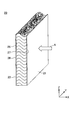
- FIG. 1 is a sectional view showing a laminated sheet according to one embodiment.
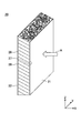
- FIG. 2 is a cross-sectional view illustrating a laminated sheet according to a modification.
- FIG. 3 is a perspective view showing a second porous layer according to one embodiment.
- FIG. 4 is a cross-sectional photograph showing a second porous layer according to one embodiment.
- FIG. 5 is a perspective view showing a second porous layer according to the first modification.
- FIG. 6 is a perspective view showing a second porous layer according to the second modification.
- FIG. 7 is a diagram illustrating a method for manufacturing a second porous layer according to one embodiment.
- FIG. 8 is a diagram showing an example of an organic fiber layer formed between the two collectors shown in FIG. FIG.
- FIG. 9 is a perspective view showing a second porous layer according to the third modification.
- FIG. 10 is a cross-sectional photograph showing a second porous layer according to a third modification.
- FIG. 11 is a diagram illustrating a method for manufacturing the second porous layer according to the third modification.
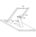
- FIG. 12 is a diagram illustrating an example of the combustion test apparatus.
- FIG. 1 is a sectional view showing a laminated sheet according to one embodiment.
- the laminated sheet 2 has a first porous layer 10 and a second porous layer 20.
- the first porous layer 10 improves the fire resistance of the laminated sheet 2 and includes a plurality of at least one of inorganic fibers and carbonized fibers.
- the second porous layer 20 improves the soundproofing of the laminated sheet 2 and is formed of a plurality of organic fibers.
- the first porous layer 10 is provided on the fire source side with respect to the second porous layer 20 because the first porous layer 10 improves the fire resistance of the laminated sheet 2.
- the temperature of the second porous layer 20 can be suppressed below the temperature at which the organic fibers forming the second porous layer 20 are thermally decomposed.
- the form of the first porous layer 10 may be any of woven cloth, nonwoven cloth, felt and the like.
- the second porous layer 20 is provided on the sound source side with reference to the first porous layer 10 because the second porous layer 20 improves the soundproofness of the laminated sheet 2. It may be arranged on the side opposite to the sound source with reference to 10. This is because sound waves can pass through the first porous layer 10.
- the form of the second porous layer 20 may be any of woven fabric, nonwoven fabric, felt, and the like.
- the first porous layer 10 and the second porous layer 20 may be separately formed and then combined.
- an adhesive is used.
- the adhesive a hot melt such as a thermoplastic resin or a double-sided tape is used.
- the double-sided tape may have no base material for the purpose of improving the flame resistance.
- the adhesive may be formed, for example, in a net shape so that sound waves can easily pass through the adhesive.
- a needle punch may be used instead of the adhesive.
- the needle punching method is a method in which the first porous layer 10 and the second porous layer 20 are overlapped, and the fibers are entangled in the vicinity of the interface between the first porous layer 10 and the second porous layer 20.
- the laminated sheet 2 may have a third porous layer 30 disposed on the opposite side of the first porous layer 10 with respect to the second porous layer 20.
- the third porous layer 30 includes a plurality of at least one of inorganic fibers and carbonized fibers.
- the configuration of the third porous layer 30 is the same as the configuration of the first porous layer 10, and a description thereof will be omitted.
- the laminated sheet 2 is used, for example, as a soundproof material for attenuating incident sound waves.
- the laminated sheet 2 attenuates the incident sound wave by converting the energy of the incident sound wave into the energy of heat.
- the air vibrates inside the porous laminated sheet 2, so that friction occurs between the fibers forming the laminated sheet 2 and the air, and the energy of the sound waves is converted into heat energy. Is done.
- Laminated sheet 2 may be used as a sound absorbing material or as a sound insulating material.
- the sound absorbing material is used for the purpose of suppressing reflection of sound waves incident from a sound source.
- the sound insulating material is used for the purpose of suppressing transmission of sound waves incident from a sound source.
- the laminated sheet 2 may serve as both a sound absorbing material and a sound insulating material.
- the laminated sheet 2 is used for noise control of vehicles, buildings, household electric appliances, large electric appliances and the like.
- the vehicle include a vehicle such as an automobile and a train, an airplane, and the like.
- the vehicle noise includes a running sound, a reflected sound of the running sound reflected on a tunnel, a sound insulating wall, or the like, and an operation sound of an on-board device (for example, an air conditioner or an engine) mounted on the vehicle.
- Examples of the building include a factory, a movie theater, a karaoke box, a music hall, and the like.
- the home electric appliance include a refrigerator, a vacuum cleaner, an outdoor unit of an air conditioner, a home storage battery, a hot water washing toilet seat, and the like.
- the large-sized electric device include a commercial refrigerator.
- the areal density of the laminated sheet 2 is, for example, 400 g / m 2 or more 1550 g / m 2 or less.
- the areal density of the laminated sheet 2 is 1550 g / m 2 or less, the lightweight property of the laminated sheet 2 is good.
- the areal density of the laminated sheet 2 is 400 g / m 2 or more, the thickness D0 of the laminated sheet 2 is not too thin, so that sound waves are easily absorbed inside the laminated sheet 2. Therefore, transmission of sound waves can be suppressed, and good sound insulation can be obtained.
- the areal density of the laminated sheet 2 is preferably 500 g / m 2 or more 1450 g / m 2 or less.
- the thickness D0 of the laminated sheet 2 is, for example, 1 mm or more and 100 mm or less. When the thickness D0 of the laminated sheet 2 is 100 mm or less, the lightweight property of the laminated sheet 2 is good. When the thickness D0 of the laminated sheet 2 is 100 mm or less, the thickness D0 of the laminated sheet 2 is not too thick, so that sound waves are easily incident on the laminated sheet 2. Therefore, reflection of sound waves can be suppressed, and good sound absorbing properties can be obtained. On the other hand, if the thickness D0 of the laminated sheet 2 is 1 mm or more, the thickness D0 of the laminated sheet 2 is not too thin, so that sound waves are easily absorbed inside the laminated sheet 2. Therefore, transmission of sound waves can be suppressed, and good sound insulation can be obtained.
- the thickness D0 of the laminated sheet 2 is preferably 5 mm or more and 80 mm or less.
- the damping constant of the laminated sheet 2 is, for example, 10 Neper / m or more and 30 Neper / m or less.
- the attenuation constant of the laminated sheet 2 is 10 Neper / m or more, sound waves incident on the laminated sheet 2 are easily absorbed inside the laminated sheet 2. Therefore, transmission of sound waves can be suppressed, and good sound insulation can be obtained.
- the attenuation constant of the laminated sheet 2 is 30 Neper or less, the acoustic wave is likely to enter the laminated sheet 2 because the bulk density of the laminated sheet 2 is not too high. Therefore, reflection of sound waves can be suppressed, and good sound absorbing properties can be obtained.
- the damping constant of the laminated sheet 2 is preferably from 12 Neper / m to 25 Neper / m.
- the characteristic impedance of the laminated sheet 2 is, for example, 300 N ⁇ s / m 3 or more and 1400 N ⁇ s / m 3 or less.
- the characteristic impedance indicates the difficulty in transmitting sound waves. As the characteristic impedance increases, the propagation of the sound wave is more likely to be hindered, and the sound wave is more likely to be reflected.
- the characteristic impedance of the laminated sheet 2 is 300 N ⁇ s / m 3 or more, sound waves incident on the laminated sheet 2 are easily absorbed inside the laminated sheet 2. Therefore, transmission of sound waves can be suppressed, and good sound insulation can be obtained.
- the characteristic impedance of the laminated sheet 2 is 1400 N ⁇ s / m 3 or less, sound waves are likely to enter the laminated sheet 2. Therefore, reflection of sound waves can be suppressed, and good sound absorbing properties can be obtained.
- the first porous layer 10 improves the fire resistance of the laminated sheet 2 and includes a plurality of at least one of inorganic fibers and carbonized fibers.
- the inorganic fibers include glass fibers, ceramic fibers, metal fibers, and carbon fibers.
- the semi-lac fiber is, for example, a silica fiber.
- the metal fiber is, for example, an aluminum fiber or a copper fiber.
- the carbon fiber is obtained by entirely carbonizing polyacrylonitrile fiber.
- the carbonized fiber is obtained by partially carbonizing polyacrylonitrile fiber.
- carbonized fibers are obtained by heating polyacrylonitrile fibers at a temperature of 200 ° C. or more and 300 ° C.
- the first porous layer 10 may include a plurality of types of inorganic fibers. Further, the first porous layer 10 may include both inorganic fibers and carbonized fibers.
- the thickness D1 of the first porous layer 10 is, for example, 0.5 mm or more and 10 mm or less.
- the thickness D1 of the first porous layer 10 is preferably 0.7 mm or more and 7 mm or less, and more preferably 0.9 mm or more and 5 mm or less.
- Heat transmission coefficient of the first porous layer 10 is, for example, less 5.0W / m 2 ⁇ K or more 1.0 ⁇ 10 3 W / m 2 ⁇ K.
- ⁇ 1 is the thermal conductivity of the first porous layer 10
- D1 is the thickness of the first porous layer 10.
- the deformation rate is the ratio of the area of the main surface that is deformed by heat when the total area of the main surface of the second porous layer 20 opposite to the fire source is defined as 100%.
- the heat transmission coefficient of the first porous layer 10 is 5.0 W / m 2 ⁇ K or more, the thickness D1 of the first porous layer 10 is not too thick, so that the light weight of the laminated sheet 2 is good. It is.
- Heat transmission coefficient of the first porous layer 10 is preferably not more than 6.7W / m 2 ⁇ K or more 7.7 ⁇ 10 2 W / m 2 ⁇ K, more preferably 1.0 ⁇ 10 1 W / m 2 ⁇ K or more and 5.9 ⁇ 10 2 W / m 2 ⁇ K or less.
- FIG. 3 is a perspective view showing a second porous layer according to one embodiment.
- FIG. 4 is a cross-sectional photograph showing a second porous layer according to one embodiment. 3 and 4, the X-axis direction, the Y-axis direction, and the Z-axis direction are directions perpendicular to each other.
- the X-axis direction is the thickness direction of the second porous layer.
- the Y-axis direction and the Z-axis direction are in-plane directions of the second porous layer.
- the Z-axis direction is the direction in which the plurality of nonwoven fabric layers are arranged.
- the arrow A indicates the incident direction of the sound wave on the second porous layer 20.
- the sound wave is incident perpendicularly to the main surface 21 of the second porous layer 20, but may be incident obliquely.
- the sound wave may be incident from both sides of the second porous layer 20 or may be incident on both of the two main surfaces 21 and 22.
- the second porous layer 20 attenuates incident sound waves.
- the second porous layer 20 attenuates the incident sound wave by converting the energy of the incident sound wave into the energy of heat.
- a sound wave enters the second porous layer 20, the air vibrates inside the second porous layer 20, so that friction occurs between the organic fibers forming the second porous layer 20 and the air, and the sound wave Energy is converted to heat energy.
- the second porous layer 20 may be used as a sound absorbing material or may be used as a sound insulating material.
- the sound absorbing material is used for the purpose of suppressing reflection of sound waves incident from a sound source.
- the sound insulating material is used for the purpose of suppressing transmission of sound waves incident from a sound source.
- the second porous layer 20 may serve as both a sound absorbing material and a sound insulating material.
- the second porous layer 20 is formed of a plurality of organic fibers.
- the organic fiber is not particularly limited, and for example, polyester fiber, polyolefin-based resin fiber, polyamide fiber, acrylic fiber, nylon fiber, and the like can be used. Among these, polyolefin-based resin fibers are particularly preferable from the viewpoint of weight reduction.
- the second porous layer 20 may be formed of one type of organic fiber, or may be formed of a plurality of types of organic fibers.
- the second porous layer 20 may include an additive in addition to the organic fiber.
- the additive is, for example, a flame retardant.
- the flame retardant may be an organic flame retardant or an inorganic flame retardant.
- Examples of the organic flame retardant include a phosphorus compound, a halogen compound, a nitrogen compound, a silicone compound, and a boron compound.
- Examples of the inorganic flame retardant include metal hydrate, antimony trioxide, and inorganic phosphorus.
- the additive may be a water repellent. Examples of the water repellent include a fluorine-based compound.
- Other additives include a weather resistance stabilizer, an antioxidant, a coloring agent, and the like. Additives may be coated on the organic fibers.
- the second porous layer 20 is formed of, for example, organic fibers having an average fiber diameter of 0.5 ⁇ m or more and 14 ⁇ m or less.
- the average fiber diameter of the second porous layer 20 is preferably 1 ⁇ m or more and 14 ⁇ m or less, more preferably 1.5 ⁇ m or more and 10 ⁇ m or less.
- the second porous layer 20 is composed of a solid such as an organic fiber having an average fiber diameter of 0.5 ⁇ m or more and 14 ⁇ m or less, and a void formed between the organic fibers.
- the present inventor focused on the solid occupancy S, which has not been focused on in the past, in order to improve the soundproofing of the second porous layer 20.
- the solid occupancy S is a ratio of the solid when the total volume of the solid and the voids in the unit volume of the second porous layer 20 is 100%. That is, the solid occupancy S is a value (BD / TD ⁇ 100) obtained by multiplying the value (BD / TD) obtained by dividing the bulk density (BD) of the second porous layer 20 by the true density (TD) of the solid by 100 (BD / TD ⁇ 100). It is.
- the solids occupancy S is equal to 100 minus the porosity.
- the larger the solid occupancy S the larger the contact area between the organic fiber having an average fiber diameter of 0.5 ⁇ m or more and 14 ⁇ m or less and air, and the efficiency of converting sound energy into heat energy by friction between the organic fiber and air. Is improved, so that soundproofing is improved.
- the smaller the solid occupancy S the lower the density and the weight can be reduced.
- the solid occupancy S is 1.0% or more and 8.0% or less.
- the solid occupation ratio S is 1.0% or more, sound waves are easily attenuated by friction between the organic fibers having an average fiber diameter of 0.5 ⁇ m or more and 14 ⁇ m or less and air, and achieve an attenuation constant of 10 Neper / m or more. Can be.
- the solid occupation ratio S is 8.0% or less, the weight can be reduced.
- the solid occupation ratio S is preferably 1.3% or more and 7.0% or less, and more preferably 1.4% or more and 6.0% or less.
- the solid mainly contains organic fibers having an average fiber diameter of 0.5 ⁇ m or more and 14 ⁇ m or less.
- the solid may include organic fibers having a fiber diameter of 10 ⁇ m or more and 30 ⁇ m or less.
- the average fiber diameter may be 0.5 ⁇ m or more and 14 ⁇ m or less.
- the solid may include low-melting organic fibers or sticky organic fibers for maintaining the shape of the second porous layer 20. Further, the solid may contain the above-mentioned additive in a range that does not impair the soundproofing property.
- the thickness D2 of the second porous layer 20 is, for example, 1 mm or more and 100 mm or less. When the thickness D2 of the second porous layer 20 is 1 mm or more, the shape of the second porous layer 20 can be maintained. On the other hand, when the thickness D2 of the second porous layer 20 is 100 mm or less, the weight of the second porous layer 20 can be reduced.
- the second porous layer 20 is formed of a plurality of strips that are continuously arranged between two opposing main surfaces 21 and 22 in a predetermined in-plane direction (the Z-axis direction in FIGS. 3 and 4) so as to be peelable. It has a nonwoven fabric layer 26.
- Each of the plurality of nonwoven fabric layers 26 includes a plurality of organic fibers tangled when viewed from a predetermined in-plane direction (the Z-axis direction in FIGS. 3 and 4). Adjacent nonwoven fabric layers 26 can be easily peeled off at the interface between each other.
- crimped fibers connecting the nonwoven fabric layers 26 may be inserted, but are not inserted in the present embodiment. This is because the crimped fiber has a large fiber diameter and a small specific surface area, so that it is difficult to obtain energy attenuation due to viscous resistance of air, and the attenuation constant becomes small.
- the sound wave is a wave in which the vibration of the density of the air propagates, and is a longitudinal wave (compression wave).
- a change in pressure due to the change in density of air occurs in the organic fibers.
- the organic fiber resonates.
- the organic fibers resonate, for example, when the organic fibers are arranged perpendicular to the propagation direction of the sound wave.
- the propagation of sound waves is more likely to be hindered and the sound waves are more likely to be reflected.
- the difficulty in transmitting sound waves can be evaluated by characteristic impedance. As the characteristic impedance increases, the propagation of the sound wave is more likely to be hindered, and the sound wave is more likely to be reflected.
- the propagation of sound waves is more likely to be hindered, and the attenuation of sound waves due to friction between air and the organic fibers is hindered.
- the plurality of nonwoven fabric layers 26 are continuously arranged so as to be peelable in the Z-axis direction. Therefore, for example, when a sound wave is incident in the X-axis direction as shown by an arrow A in FIG. 3, the number of organic fibers perpendicular to the sound wave propagation direction in each nonwoven fabric layer 26 can be reduced. Fiber resonance can be suppressed. As a result, the characteristic impedance can be reduced as compared with a horizontally oriented product having the same bulk density, that is, a horizontally oriented product having the same solid occupancy S.
- a structure in which the plurality of nonwoven fabric layers 26 are continuously arranged in the in-plane direction (the Z-axis direction in FIGS. 3 and 4) is called a vertical orientation, and the plurality of nonwoven fabric layers 26A are arranged in the thickness direction (FIG. 9).
- a structure continuously arranged in the Z-axis direction is also referred to as a lateral orientation.
- the solid occupancy S may be reduced to less than 1.0% (that is, the porosity may be increased to 99.0% or more). .
- the damping constant is too small and the sound insulation deteriorates. Therefore, in this embodiment, the solid occupancy S is set to 1.0% or more.
- the nonwoven fabric layer 26 is formed in a C shape as viewed in the Y-axis direction as shown in FIGS.
- the shape of the nonwoven fabric layer 26 as viewed in the Y-axis direction is C-shaped in the present embodiment, but is not particularly limited.
- the shape may be a wavy line as shown in FIG. 5 or as shown in FIG. It may be linear.
- the shape of the nonwoven fabric layer 26 as viewed in the Y-axis direction is a straight line oblique to the Z-axis direction in FIG. 6, but may be a straight line perpendicular to the Z-axis direction.
- the second porous layer 20 has a skin layer 27 on one main surface 21 and a skin layer 28 on the other main surface 22 of the two main surfaces 21 and 22 facing each other.
- Each of the two skin layers 27 and 28 is one in which a plurality of organic fibers are entangled (that is, a nonwoven fabric) when viewed from the thickness direction (the X-axis direction in FIGS. 3 and 4).
- a plurality of nonwoven fabric layers 26 are provided between the two skin layers 27 and 28, and each nonwoven fabric layer 26 is formed continuously with the two skin layers 27 and 28.
- the thickness of each of the skin layers 27 and 28 is thin, and when the adjacent nonwoven fabric layers 26 are separated at the interface between them, the skin layers 27 and 28 are separated from each other on the extended surface of the interface.
- the thickness D4 of the skin layer 27 and the thickness D5 of the skin layer 28 are each 0.01 mm or more and 5 mm or less.
- the thickness D4 and the thickness D5 are each 0.01 mm or more, unintended peeling at the interface between the adjacent nonwoven fabric layers 26 can be suppressed, and the shape can be maintained.
- the thickness D4 and the thickness D5 are each 5 mm or less, the reflection of the sound wave by the skin layer 27 can be suppressed, and the attenuation of the sound wave in the nonwoven fabric layer 26 can be promoted.
- Each of the thickness D4 and the thickness D5 is preferably 0.3 mm or more and 4 mm or less, and more preferably 0.6 mm or more and 3 mm or less.
- the method for producing the second porous layer 20 is not particularly limited, but a melt spinning method is preferable, and a melt blown method is particularly preferable.
- the melt blown method is a method in which a molten thermoplastic resin is blown out from a nozzle, stretched into a fibrous shape by a high-temperature, high-speed airflow, and spun organic fibers on a collector.
- the thermoplastic resin contains at least one of a polyolefin resin, a polyester resin, and a polyamide resin.
- the method for manufacturing the second porous layer 20 is not limited to the melt blown method, but may be, for example, an electrospinning method. According to the melt blown method or the electrospinning method, a nonwoven fabric can be obtained.
- FIG. 7 is a diagram illustrating a method for manufacturing a second porous layer according to one embodiment.
- the X-axis direction, the Y-axis direction, and the Z-axis direction in FIG. 7 have the same meaning as the X-axis direction, the Y-axis direction, and the Z-axis direction in FIGS.
- an arrow B is a transport direction (Z-axis direction) of the second porous layer 20.
- the manufacturing apparatus 100 for manufacturing the second porous layer 20 has a die 110 and two collectors 120, as shown in FIG.
- the die 110 has a resin nozzle 111 for discharging a molten resin and a gas nozzle 112 for discharging a gas such as air.
- the resin nozzle 111 discharges the molten resin, for example, vertically downward.
- the gas nozzles 112 are provided on both sides of the resin nozzle 111 in the X-axis direction, and each discharge a high-temperature gas obliquely downward so as to intersect with the flow of the molten resin discharged from the resin nozzle 111.
- a plurality of outlets of the resin nozzle 111 and outlets of the gas nozzle 112 are provided on the lower surface of the die 110 at intervals in the Y-axis direction.
- the ejection direction of the resin nozzle 111 is the Z-axis direction (more specifically, vertically downward), but may be a direction inclined with respect to the Z-axis direction.
- the surfaces of the two collectors 120 facing each other are made parallel and perpendicular to the X-axis direction.
- a transport path for the second porous layer 20 is formed between the surfaces of the two collectors 120 facing each other.
- the second porous layer 20 is transported together with the endless belt 123 in the Z-axis direction (more specifically, vertically downward), passes between the two collectors 120, is curved, and is transported horizontally.
- the thickness D2 (see FIG. 3) of the second porous layer 20 becomes smaller than the distance W between the two collectors 120 due to its own weight or the like.
- the interval W between the two collectors 120 is constant as shown in FIG. 7, but may be narrower or wider from the upstream side in the transport direction to the downstream side in the transport direction. Good.
- Each collector 120 has, for example, a first pulley 121, a second pulley 122, and an endless belt 123 bridged between the first pulley 121 and the second pulley 122.
- the axial direction of each rotation shaft of the first pulley 121 and the second pulley 122 is the Y-axis direction.
- At least one of the first pulley 121 and the second pulley 122 is a drive pulley that is rotated by a drive source such as a rotary motor. By continuously rotating the driving pulley, the second porous layer 20 is continuously transported together with the endless belt 123.
- FIG. 8 is a diagram showing an example of the organic fiber layer formed between the two collectors shown in FIG.
- the molten resin discharged from the resin nozzle 111 is stretched into a fibrous shape by the high-speed airflow discharged from the gas nozzle 112 to form the organic fiber layer 29.
- the organic fiber layer 29 is a nonwoven fabric in which a plurality of organic fibers are entangled when viewed in the Z-axis direction.
- the organic fiber layer 29 is bridged between two collectors 120 provided at an interval in the X-axis direction when viewed in the Z-axis direction.
- the X-axis direction end of the organic fiber layer 29 adheres near the upper end of the endless belt 123 as shown in FIG.
- the upper end of the endless belt 123 is held around the outer periphery of the first pulley 121, and changes its direction as the first pulley 121 rotates.
- the ends of the organic fiber layer 29 in the X-axis direction change directions and become the skin layers 27 and 28.
- the central part in the X-axis direction of the organic fiber layer 29 becomes the nonwoven fabric layer 26.
- each collector 120 has the endless belt 123 in the present embodiment, but may not have the endless belt 123.
- the at least one collector 120 may be constituted by a roll directly in contact with the second porous layer 20. In this case, a suction source for sucking the second porous layer 20 may be provided on the roll.
- the second porous layer 20 of the embodiment, the first modified example and the second modified example is a vertically oriented product, and a plurality of nonwoven fabric layers continuously arranged in the in-plane direction of the second porous layer 20. 26.
- the second porous layer 20A of the third modified example described below is a horizontally oriented product and has a plurality of nonwoven fabric layers 26A continuously arranged in the thickness direction of the second porous layer 20A.
- FIG. 9 is a perspective view showing a second porous layer according to the third modification.
- FIG. 10 is a cross-sectional photograph showing a second porous layer according to a third modification.
- the X-axis direction, the Y-axis direction, and the Z-axis direction are directions perpendicular to each other.
- the Z-axis direction is the thickness direction of the second porous layer, unlike FIGS. 3 to 8 and the like.
- the X-axis direction and the Y-axis direction are in-plane directions of the second porous layer.
- the arrow A indicates the direction of incidence of the sound wave on the second porous layer 20A.
- the sound wave is incident perpendicular to the main surface 21A of the second porous layer 20A, but may be incident obliquely.
- the sound wave may be incident on both sides of the second porous layer 20A, or may be incident on both of the two main surfaces 21A and 22A.
- the average fiber diameter of the second porous layer 20A is 0.5 ⁇ m or more and 14 ⁇ m or less, like the average fiber diameter of the second porous layer 20 of the above embodiment.
- the solid occupancy S of the second porous layer 20A is 1.0% or more and 8.0% or less, like the solid occupancy S of the second porous layer 20 of the above embodiment. Therefore, according to this modified example, similarly to the above-described embodiment, sound waves are easily attenuated by friction between the organic fibers having an average fiber diameter of 0.5 ⁇ m or more and 14 ⁇ m or less and air, and an attenuation constant of 10 Neper / m or more is achieved. can do. Further, the weight can be reduced.
- the second porous layer 20A has a plurality of nonwoven fabric layers 26A that are continuously arranged in a thickness direction (the Z-axis direction in FIGS. 9 and 10) so as to be peelable.
- Each of the plurality of nonwoven fabric layers 26A has a plurality of organic fibers tangled when viewed from the thickness direction.
- the adjacent nonwoven fabric layers 26A can be easily peeled off at the interface between each other.
- FIG. 11 is a diagram showing a method for manufacturing the second porous layer according to the third modification.
- the X-axis direction, Y-axis direction, and Z-axis direction in FIG. 11 have the same meaning as the X-axis direction, Y-axis direction, and Z-axis direction in FIG.
- the arrow B is the transport direction (X-axis direction) of the second porous layer.
- a production apparatus 100A for producing the second porous layer 20A has a die 110A and a collector 120A as shown in FIG.
- the dice 110A has a resin nozzle 111A and a gas nozzle 112A, similarly to the dice 110 of the above embodiment.
- the ejection direction of the resin nozzle 111A is the Z-axis direction (more specifically, vertically downward) in the present modification, but may be a direction inclined with respect to the Z-axis direction.
- the collector 120A has an endless belt 123A bridged between a first pulley and a second pulley (not shown).
- the upper surface of the endless belt 123A may be a horizontal plane perpendicular to the Z-axis direction.
- the second porous layer 20 is conveyed in the X-axis direction together with the endless belt 123A while being gradually formed on the upper surface of the endless belt 123A.
- Examples 1 to 14 described below examples 1 to 9 are Examples and Examples 10 to 14 are Comparative Examples.
- the flame-resistant fiber sheet and the organic fiber sheet used in Examples 1 to 14 will be individually described.
- the flame resistant fiber sheet corresponds to the first porous layer (or both the first porous layer and the third porous layer), and the organic fiber sheet corresponds to the second porous layer.
- fire-resistant fiber sheet 1 carbonized fiber felt (trade name: PC-400, thickness: 2.0 mm, area density: 400 g / m 2 , heat transmission coefficient: 20 W / m 2 ⁇ K) manufactured by Osaka Seisakusho Co., Ltd. Using.
- carbonized fiber felt (trade name: Newlastan TOP8150Z, thickness: 1.5 mm, surface density: 150 g / m 2 , heat transmission coefficient: 26 W / m 2 ⁇ K) manufactured by Asahi Kasei Advance Co., Ltd. Using.
- an alkali earth silicate wool (trade name: IBIWOOL-E paper, thickness: 1.0 mm, area density: 180 g / m 2 , heat transmission coefficient: 100 W / m 2 ⁇ K, manufactured by Ibiden Co.) was used.
- This alkali earth silicate wool contains ceramic fibers.
- an alkali earth silicate wool (trade name: IBIWOOL-E paper, thickness: 3.0 mm, area density: 540 g / m 2 , heat transmission rate: 33 W / m 2 ⁇ K, manufactured by Ibiden Co., Ltd.) was used.
- This alkali earth silicate wool contains ceramic fibers.
- a glass cloth (trade name: Marinetex 0.7A, thickness: 0.7mm, surface density: 428g / m 2 , heat transmission coefficient: 85W / m 2 ⁇ K) manufactured by Nichias Corporation is used. Using. This glass cloth contains glass fibers.
- a glass cloth (trade name: Marinetex 0.2A, thickness: 0.2 mm, surface density: 232 g / m 2 , heat transmission coefficient: 500 W / m 2 ⁇ K) manufactured by Nichias Corporation is used as the flame-resistant fiber sheet 6. Using. This glass cloth contains glass fibers.
- glass wool (trade name: Glaslon Wool GW64, thickness: 25.0 mm, surface density: 1600 g / m 2 , heat transmission coefficient: 1.3 W / m 2 ⁇ ) manufactured by Asahi Fiberglass Co., Ltd. K) was used.
- This glass wool contains glass fibers.
- glass wool manufactured by Asahi Fiber Glass Co., Ltd. (trade name: Glaslon Wool GW32, thickness: 25 mm, area density: 800 g / m 2 , heat transmission coefficient: 1.4 W / m 2 ⁇ K) was used.
- This glass wool contains glass fibers.
- Table 1 summarizes the physical properties of the flame-resistant fiber sheets 1 to 8. Since the flame-resistant fiber sheets 7 and 8 were used in place of the organic fiber sheets 1 to 6 described later, physical properties similar to those of the organic fiber sheets 1 to 6 are also shown in Table 1.
- the organic fiber sheet 1 is a vertically oriented product manufactured using the manufacturing apparatus 100 shown in FIG.
- a polypropylene resin Moplen HP461Y manufactured by POLYMIRAE was used as a raw material of the organic fiber.
- the polypropylene resin was melt-kneaded at 250 ° C. by an extruder, and then sent out to the die 110 at a discharge rate of 2.9 kg / h using a gear pump.
- the die 110 was heated to 250 ° C. in advance.
- a die in which 484 resin nozzles 111 are arranged in a line at a pitch of 0.72 mm in the Y-axis direction was used as the die 110.
- each resin nozzle 111 was in the Z-axis direction (more specifically, vertically downward), and the diameter of the discharge port of each resin nozzle 111 was 0.2 mm.
- a pair of gas nozzles 112 were provided on both sides of each resin nozzle 111 in the X-axis direction.
- the flow velocity of air in each gas nozzle 112 was set to 76 m / sec, and the temperature of air in each gas nozzle 112 was set to 270 ° C.
- the vertical distance D (see FIG. 7) between the die 110 and each collector 120 was set to 400 mm.
- the interval W between the two collectors 120 was constant at 55 mm, and the transport speed V of the organic fiber sheet by the two collectors 120 was set to 0.25 m / min.
- the organic fiber sheet 2 has the same conditions as those of the organic fiber sheet 1 except for the conditions of the die temperature, the resin discharge amount, the diameter of the discharge port of the resin nozzle, the air temperature, the air flow rate, the vertical distance D, and the transport speed V. It is a manufactured vertically oriented product. Die temperature is 260 ° C, resin discharge amount is 1.5kg / h, resin nozzle discharge port diameter is 0.15mm, air temperature is 300 ° C, air flow rate is 39m / sec, vertical distance D is 300mm, transport speed V was set to 0.2 m / min.
- the organic fiber sheet 3 is manufactured under the same conditions as the above-described organic fiber sheet 1 except for the conditions of the die temperature, the resin discharge amount, the diameter of the discharge port of the resin nozzle, the air temperature, the air flow rate, the distance W between the collectors, and the transport speed V. It is a vertically oriented product.
- the die temperature is 260 ° C
- the resin discharge rate is 5.8 kg / h
- the diameter of the resin nozzle discharge port is 0.15 mm
- the air temperature is 285 ° C
- the air flow rate is 116 m / sec
- the distance W between the collectors is 40 mm
- the transport speed V was set to 0.2 m / min.
- the organic fiber sheet 4 has the same conditions as those of the organic fiber sheet 1 except for the conditions of the die temperature, the resin discharge amount, the diameter of the discharge port of the resin nozzle, the air temperature, the air flow rate, the vertical distance D, and the transport speed V. It is a manufactured vertically oriented product. Die temperature is 260 ° C, resin discharge rate is 5.8kg / h, resin nozzle discharge port diameter is 0.15mm, air temperature is 295 ° C, air flow rate is 77m / sec, vertical distance D is 300mm, transport speed V was set to 0.5 m / min.
- the organic fiber sheet 5 is a horizontally oriented product manufactured using the manufacturing apparatus 100A shown in FIG.
- a polypropylene resin Moplen HP461Y manufactured by POLYMIRAE was used as a raw material of the organic fiber.
- the polypropylene resin was melt-kneaded at 260 ° C. by an extruder, and then sent out to a die 110A at a discharge rate of 2.9 kg / h using a gear pump.
- Die 110A was previously heated to 260 ° C.
- a die in which 484 resin nozzles 111A were arranged in a line at a pitch of 0.72 mm in the Y-axis direction was used as the die 110A.
- each resin nozzle 111A was in the Z-axis direction (more specifically, vertically downward), and the diameter of the discharge port of each resin nozzle 111A was 0.15 mm.
- a pair of gas nozzles 112A are provided on both sides in the X-axis direction of each resin nozzle 111A.
- the flow velocity of air in each gas nozzle 112A is set to 77 m / sec, and the temperature of air in each gas nozzle 112 is set to 295 ° C.
- the vertical distance D (see FIG. 11) between the die 110A and the collector 120A was set to 700 mm.
- the upper surface of the collector 120A was a horizontal plane perpendicular to the Z-axis direction.
- the transport speed V of the organic fiber sheet by the collector 120A was set to 0.3 m / min.
- Table 2 summarizes the manufacturing conditions for the organic fiber sheets 1 to 5.
- the organic fiber sheet 6 As the organic fiber sheet 6, a commercially available PET felt was used.
- the thickness of the organic fiber sheet was measured by placing a test piece cut from the organic fiber sheet on a horizontal mounting surface of a table, measuring the thickness of the five points near the center of the test piece with a thickness gauge from above, and measuring the thickness of the five points. The arithmetic mean of the measured values was used.
- the test piece was cut into a rectangular shape having a length of 100 mm and a width of 100 mm when viewed from a direction perpendicular to the main surface of the organic fiber sheet. The test piece was placed on the mounting surface of the table so that the cut surface of the test piece was perpendicular to the mounting surface of the table.
- the test piece was cut out from the center of the organic fiber sheet in the Y-axis direction (see FIGS. 7 and 11) into a rectangular shape having a length of 100 mm and a width of 100 mm when viewed from a direction perpendicular to the main surface of the organic fiber sheet.
- the arithmetic mean value of the thickness of three points of one skin layer and the arithmetic mean value of the thickness of three points of the other skin layer matched within an error range.
- the average fiber diameter of the organic fiber sheet was measured by image analysis of a SEM photograph (scanning electron micrograph) of a test piece cut from the organic fiber sheet.
- the test piece was cut into a rectangular shape having a length of 5 mm and a width of 10 mm as viewed from a direction perpendicular to the main surface of the organic fiber sheet.
- a Pt film was previously formed on the cut surface of the test piece for measuring the average fiber diameter using a sputtering apparatus.
- a sputtering device a magnetron sputtering device MSP-15 manufactured by Vacuum Devices, Inc. was used.
- the current value was 30 mA, and the deposition time was 30 seconds.
- proX PREMIUMII manufactured by Phenom-World was used as a scanning electron microscope (SEM).
- the beam energy of the electron beam was set to 10 KeV.
- 30 electronic images were obtained using Automated Image Mapping of the Pro Suite phenom application system manufactured by Phenom-World while changing the imaging location at a magnification of 1500 times.
- a total of 1000 fiber diameters were measured by image analysis from the 30 electronic images, and the arithmetic average of the measured fiber diameters was defined as the average fiber diameter.
- the fiber metrics function of the Phenom-World Pro Suite phenom application system was used.
- the solid occupancy of the organic fiber sheet is determined as a value (BD / TD ⁇ 100) obtained by multiplying 100 by a value (BD / TD) obtained by dividing the bulk density (BD) of the organic fiber sheet by the true density (TD) of the solid.
- the bulk density (BD) of the organic fiber sheet was obtained by dividing the mass of the test piece cut from the organic fiber sheet by the volume of the test piece.
- the test piece was cut into a circular shape having a diameter of 100.5 mm as viewed from a direction perpendicular to the main surface of the organic fiber sheet.
- the volume of the test piece was measured by multiplying the circular area having a diameter of 100.5 mm by the total thickness of the organic fiber sheet.
- the mass of the test piece was measured with an electronic balance.
- the true density of the organic fibers constituting the solid was used as the true density of the solid.
- the true density of the polypropylene resin Moplen HP461Y manufactured by POLYMIRAE used as a material for the organic fiber was 920 kg / m 3 .
- the attenuation constant (unit: Neper / m) of the organic fiber sheet was measured according to JIS A 1405-2 using a normal incidence sound absorption coefficient measurement system WinZacMTX manufactured by Nippon Acoustic Engineering. Specifically, a sound wave is vertically incident on a plane on one side of the cylindrical test piece used for the measurement of the solid occupancy, and each attenuation when the frequency of the sound wave is changed from 200 Hz to 1000 Hz at a pitch of 20 Hz. The constants were measured, and the arithmetic average of the measured values at 41 points was defined as the attenuation constant of the organic fiber sheet. Note that the attenuation constant having a frequency of less than 200 Hz has a large measurement error, and is therefore excluded from the measurement.
- the characteristic impedance (unit: N ⁇ s / m 3 ) of the organic fiber sheet is measured in accordance with JIS A 1405-2 using the normal incidence sound absorption coefficient measurement system WinZacMTX manufactured by Nippon Acoustic Engineering Co., Ltd. in the same manner as the attenuation constant. It was measured. Specifically, each characteristic is obtained when a sound wave is vertically incident on a plane on one side of the cylindrical test piece used for measuring the solid occupancy, and the frequency of the sound wave is changed from 200 Hz to 1000 Hz at a pitch of 20 Hz. The impedance (more specifically, the real part of the characteristic impedance) was measured, and the arithmetic average of the measured values at 41 points was defined as the characteristic impedance of the organic fiber sheet.
- Table 3 summarizes the physical properties of the organic fiber sheets 1 to 6.
- the organic fiber sheets 1 to 5 had a high attenuation constant because the average fiber diameter was in the range of 0.5 ⁇ m to 14 ⁇ m and the solid occupancy S was in the range of 1.0% to 8.0%. (10 Neper / m or more) was obtained. On the other hand, since the average fiber diameter of the organic fiber sheet 6 was larger than 14 ⁇ m, the attenuation constant was low.
- Example 1 a test sheet 1 was produced by bonding one flame-resistant fiber sheet 1 and one organic fiber sheet 1 with hot melts with their main surfaces facing each other.
- Example 2 as in Example 1, one test sheet 2 was produced by bonding one flame-resistant fiber sheet 1 and one organic fiber sheet 1 with hot melt with their main surfaces facing each other.
- Example 3 a test sheet 3 was produced by sandwiching one organic fiber sheet 1 between two flame-resistant fiber sheets 1 and bonding them with a hot melt.
- Example 4 a test sheet 4 was produced by bonding one flame-resistant fiber sheet 2 and one organic fiber sheet 2 with hot melt with their main surfaces facing each other.
- Example 5 a test sheet 5 was produced by bonding one flame-resistant fiber sheet 2 and one organic fiber sheet 3 with their main surfaces facing each other with hot melt.
- Example 6 a test sheet 6 was produced by bonding one flame-resistant fiber sheet 3 and one organic fiber sheet 4 with their main surfaces facing each other with hot melt.
- Example 7 a test sheet 7 was produced by bonding one flame-resistant fiber sheet 3 and one organic fiber sheet 5 with hot melt with their main surfaces facing each other.
- Example 8 a test sheet 8 was produced by bonding one flame-resistant fiber sheet 5 and one organic fiber sheet 4 with their main surfaces facing each other with hot melt.
- Example 9 a test sheet 9 was produced by bonding one flame-resistant fiber sheet 6 and one organic fiber sheet 5 with their main surfaces facing each other with hot melt.
- Example 10 only one flame-resistant fiber sheet 7 was used as the test sheet 10.
- the test sheet 11 was produced by bonding one flame-resistant fiber sheet 1 and one flame-resistant fiber sheet 8 with their main surfaces facing each other with hot melt.
- Example 12 only one organic fiber sheet 1 was used as the test sheet 12.
- Example 13 a test sheet 13 was produced by bonding one flame-resistant fiber sheet 4 and one organic fiber sheet 3 with hot melts with their main surfaces facing each other.
- Example 14 a test sheet 14 was produced by bonding one flame-resistant fiber sheet 1 and one organic fiber sheet 6 with hot melt with their main surfaces facing each other.
- the organic fiber sheet was arranged on the sound source side, and the flame-resistant fiber sheet was arranged on the opposite side to the sound source.
- the flame-resistant fiber sheet 8 was arranged on the sound source side, and the flame-resistant fiber sheet 1 was arranged on the side opposite to the sound source.
- test sheets 3, 10, and 12 had a structure symmetrical in the thickness direction, and thus were appropriately arranged.
- the sound insulation was determined to be acceptable when the attenuation constant was 10 Neper / m or more, and was determined to be unacceptable otherwise.
- the sound absorption was determined to be acceptable when the characteristic impedance was 1400 N ⁇ s / m 3 or less, and was determined to be unacceptable otherwise.
- a combustion test was performed in accordance with a railway vehicle material combustion test (general material; 45 ° ethyl alcohol test of nonmetallic materials for railway vehicles) by the Japan Railway Rolling Stock Machine Technology Association.
- 201 indicates a specimen (182 mm ⁇ 257 mm)
- 202 indicates an alcohol container (iron 17.5 ⁇ ⁇ 7.1, 0.8 t)
- 203 indicates a container holder made of cork.
- the specimen 201 was held at an angle of 45 ° with respect to the horizontal plane.
- the specimen 201 is the test sheets 1 to 14.
- the fuel container (alcohol container) 202 was placed on a cork container holder 203 such that the center of the bottom of the fuel container 202 was positioned 25.4 mm vertically below the center of the lower surface of the specimen 201.
- the fire-resistant fiber sheet 1 was disposed on the fire source side (lower side), and the fire-resistant fiber sheet 8 was disposed on the opposite side (upper side) from the fire source.
- test sheets 3, 10, and 12 had a structure symmetrical in the thickness direction, and thus were appropriately arranged.
- the deformation rate is a ratio of the area of the upper surface of the test piece 201 that is deformed by heat when the total area of the upper surface (182 mm ⁇ 257 mm) of the test piece 201 is set to 100%.
- Tables 4 and 5 show the evaluation results of Test Sheets 1 to 14.
- the test sheets 1 to 9 are different from the test sheets 10 to 14 and satisfy all of the following requirements (1) to (4). Therefore, all of the lightness, soundproofing, flame resistance and flexibility are judged to be acceptable.
- the test sheet includes at least one flame resistant fiber sheet and one organic fiber sheet.
- the surface density of the test sheet is 400 g / m 2 or more 1550 g / m 2 or less.
- the organic fiber sheet is formed of organic fibers having an average fiber diameter of 0.5 ⁇ m or more and 14 ⁇ m or less.
- the solid occupancy of the organic fiber sheet is 1.0% or more and 8.0% or less.
- test sheet 10 was composed only of the flame-resistant fiber sheet 7 having an areal density exceeding 1550 g / m 2 , it was determined to be unacceptable for lightness and flexibility.
- the test sheet 11 has a flame-resistant fiber sheet 8 having a solid occupancy of less than 1.0% instead of the organic fiber sheet 1 having a solid occupancy of 1.0% or more. Therefore, it was determined that the soundproofing property (especially the soundproofing property) was rejected.
- the test sheet 12 since the test sheet 12 has only the organic fiber sheet 1 unlike the test sheet 1, the test sheet 12 was determined to be unacceptable in terms of flame resistance.
- the test sheet 13 had an areal density exceeding 1550 g / m 2 , it was determined to be unacceptable for lightness.
- the test sheet 14 had an area density exceeding 1550 g / m 2 , it was determined to be unacceptable for lightness.
- the test sheet 1 and the test sheet 2 have the same one organic fiber sheet 1 and the same one flame-resistant fiber sheet 1.
- the organic fiber sheet 1 is arranged on the sound source side, the organic fiber sheet 1 is arranged on the opposite side to the sound source. Also, it can be seen that good soundproofing is obtained.
- the test sheets 1 and 2 have the flame-resistant fiber sheet 1 on one side of the organic fiber sheet 1, whereas the test sheet 3 has the flame-resistant fiber sheet 1 on both sides of the organic fiber sheet 1.
- the test sheets 1 and 2 have the flame-resistant fiber sheet 1 on one side of the organic fiber sheet 1
- the test sheet 3 has the flame-resistant fiber sheet 1 on both sides of the organic fiber sheet 1.
- the laminated sheet of the above embodiment is used as a soundproofing material for attenuating incident sound waves, but may be used for applications other than the soundproofing material.
- Applications other than the soundproofing material include a heat insulating material, a vibration damping material, and a shock absorbing material.
Landscapes
- Engineering & Computer Science (AREA)
- Textile Engineering (AREA)
- Physics & Mathematics (AREA)
- Acoustics & Sound (AREA)
- Multimedia (AREA)
- Soundproofing, Sound Blocking, And Sound Damping (AREA)
- Laminated Bodies (AREA)
- Nonwoven Fabrics (AREA)
Abstract
Cette invention concerne une feuille stratifiée qui comprend : une première couche poreuse qui comprend de multiples brins de fibre inorganique et/ou de multiples brins de fibre carbonisée ; et une seconde couche poreuse qui est formée par de multiples brins de fibre organique, la densité de surface de la feuille stratifiée étant de 400-1550 g/m2, la seconde couche poreuse étant formée par une fibre organique ayant un diamètre de fibre moyen de 0,5 à 14 µm, et lorsque le volume total de la substance solide et des interstices par unité de volume de la seconde couche poreuse est défini comme étant de 100 %, la proportion de la substance solide représente de 1,0 à 8,0 %.
Priority Applications (3)
| Application Number | Priority Date | Filing Date | Title |
|---|---|---|---|
| US17/269,452 US11951729B2 (en) | 2018-08-23 | 2019-05-30 | Laminated sheet |
| EP19852943.0A EP3842227B1 (fr) | 2018-08-23 | 2019-05-30 | Feuille laminée |
| CN201980054235.XA CN112566780B (zh) | 2018-08-23 | 2019-05-30 | 层叠片材 |
Applications Claiming Priority (2)
| Application Number | Priority Date | Filing Date | Title |
|---|---|---|---|
| JP2018-156312 | 2018-08-23 | ||
| JP2018156312A JP7097781B2 (ja) | 2018-08-23 | 2018-08-23 | 積層シート |
Publications (1)
| Publication Number | Publication Date |
|---|---|
| WO2020039681A1 true WO2020039681A1 (fr) | 2020-02-27 |
Family
ID=69592614
Family Applications (1)
| Application Number | Title | Priority Date | Filing Date |
|---|---|---|---|
| PCT/JP2019/021517 Ceased WO2020039681A1 (fr) | 2018-08-23 | 2019-05-30 | Feuille stratifiée |
Country Status (5)
| Country | Link |
|---|---|
| US (1) | US11951729B2 (fr) |
| EP (1) | EP3842227B1 (fr) |
| JP (1) | JP7097781B2 (fr) |
| CN (1) | CN112566780B (fr) |
| WO (1) | WO2020039681A1 (fr) |
Cited By (1)
| Publication number | Priority date | Publication date | Assignee | Title |
|---|---|---|---|---|
| JPWO2022186289A1 (fr) * | 2021-03-03 | 2022-09-09 |
Citations (7)
| Publication number | Priority date | Publication date | Assignee | Title |
|---|---|---|---|---|
| JPS63121530U (fr) * | 1987-01-30 | 1988-08-08 | ||
| JP2001271438A (ja) * | 2000-03-24 | 2001-10-05 | Bridgestone Corp | 屋外用吸音材 |
| JP2001316961A (ja) * | 2000-05-09 | 2001-11-16 | Toyobo Co Ltd | 吸音構造体 |
| JP2008076871A (ja) | 2006-09-22 | 2008-04-03 | Swcc Showa Device Technology Co Ltd | 吸音体およびこれを用いた吸音構造 |
| JP2014232281A (ja) * | 2013-05-30 | 2014-12-11 | 帝人株式会社 | 吸音材 |
| JP2018156312A (ja) | 2017-03-16 | 2018-10-04 | Kddi株式会社 | 端末装置、情報管理装置、データ管理方法、及びコンピュータプログラム |
| WO2019107019A1 (fr) * | 2017-11-28 | 2019-06-06 | 日東電工株式会社 | Feuille de fibres poreuse |
Family Cites Families (19)
| Publication number | Priority date | Publication date | Assignee | Title |
|---|---|---|---|---|
| US3795288A (en) * | 1968-05-27 | 1974-03-05 | Pall Corp | Gas conduit with acoustic insulation comprising anisometric compressed and bonded multilayer knitted wire mesh composites |
| JPS5668152A (en) | 1979-11-01 | 1981-06-08 | Toa Nenryo Kogyo Kk | Nonwoven fabric |
| US7476632B2 (en) * | 2002-11-15 | 2009-01-13 | 3M Innovative Properties Company | Fibrous nonwoven web |
| JP2005335279A (ja) | 2004-05-28 | 2005-12-08 | Du Pont Toray Co Ltd | 易成形性吸音材 |
| JP2006002429A (ja) | 2004-06-17 | 2006-01-05 | Nihon Glassfiber Industrial Co Ltd | 電波音波吸収断熱体 |
| US7461437B2 (en) * | 2004-11-15 | 2008-12-09 | Velcro Industries B.V. | Articles and methods of their formation |
| BRPI0821434A2 (pt) * | 2007-12-28 | 2015-06-16 | 3M Innovative Properties Co | Mantas fibrosas não-tecidas compósitas e métodos de preparo e utilização das mesmas |
| CN101195938B (zh) | 2008-01-08 | 2010-08-11 | 中国人民解放军国防科学技术大学 | 一种皮芯结构微孔碳化硅纤维及其制备方法 |
| US8486516B2 (en) * | 2008-08-29 | 2013-07-16 | Certainteed Gypsum, Inc. | Plastic coated composite building boards and method of making same |
| KR101233813B1 (ko) * | 2010-07-12 | 2013-02-14 | (주)리앤에스 | 열가소성 유기 섬유, 그 제조 방법, 이를 이용한 섬유 복합 보드 및 그 제조 방법 |
| EP2503040A1 (fr) * | 2011-03-23 | 2012-09-26 | Autoneum Management AG | Garniture multicouches moulée |
| WO2013005744A1 (fr) * | 2011-07-05 | 2013-01-10 | 豊和繊維工業株式会社 | Plage arrière pour véhicule |
| JP5863474B2 (ja) | 2012-01-20 | 2016-02-16 | 三井化学株式会社 | メルトブローン不織布、その用途、及びその製造方法 |
| US20130327705A1 (en) * | 2012-06-08 | 2013-12-12 | Edward J. Clark | Heated collectors, nonwoven materials produced therefrom, and methods relating thereto |
| KR101665895B1 (ko) | 2012-08-23 | 2016-10-12 | 미쓰이 가가쿠 가부시키가이샤 | 멜트블로운 부직포 및 그의 용도 |
| US10961644B2 (en) * | 2014-01-29 | 2021-03-30 | Biax-Fiberfilm Corporation | High loft, nonwoven web exhibiting excellent recovery |
| JP6426707B2 (ja) | 2014-03-25 | 2018-11-21 | 林テレンプ株式会社 | 自動車用サイレンサー |
| EP3450596B1 (fr) | 2016-04-27 | 2024-08-21 | Toray Industries, Inc. | Fibre poreuse, matériau adsorbant et colonne de purification |
| JP6614450B2 (ja) | 2016-05-11 | 2019-12-04 | パナソニックIpマネジメント株式会社 | 不織布及び吸音材 |
-
2018
- 2018-08-23 JP JP2018156312A patent/JP7097781B2/ja active Active
-
2019
- 2019-05-30 CN CN201980054235.XA patent/CN112566780B/zh active Active
- 2019-05-30 US US17/269,452 patent/US11951729B2/en active Active
- 2019-05-30 WO PCT/JP2019/021517 patent/WO2020039681A1/fr not_active Ceased
- 2019-05-30 EP EP19852943.0A patent/EP3842227B1/fr active Active
Patent Citations (7)
| Publication number | Priority date | Publication date | Assignee | Title |
|---|---|---|---|---|
| JPS63121530U (fr) * | 1987-01-30 | 1988-08-08 | ||
| JP2001271438A (ja) * | 2000-03-24 | 2001-10-05 | Bridgestone Corp | 屋外用吸音材 |
| JP2001316961A (ja) * | 2000-05-09 | 2001-11-16 | Toyobo Co Ltd | 吸音構造体 |
| JP2008076871A (ja) | 2006-09-22 | 2008-04-03 | Swcc Showa Device Technology Co Ltd | 吸音体およびこれを用いた吸音構造 |
| JP2014232281A (ja) * | 2013-05-30 | 2014-12-11 | 帝人株式会社 | 吸音材 |
| JP2018156312A (ja) | 2017-03-16 | 2018-10-04 | Kddi株式会社 | 端末装置、情報管理装置、データ管理方法、及びコンピュータプログラム |
| WO2019107019A1 (fr) * | 2017-11-28 | 2019-06-06 | 日東電工株式会社 | Feuille de fibres poreuse |
Non-Patent Citations (1)
| Title |
|---|
| See also references of EP3842227A4 |
Cited By (3)
| Publication number | Priority date | Publication date | Assignee | Title |
|---|---|---|---|---|
| JPWO2022186289A1 (fr) * | 2021-03-03 | 2022-09-09 | ||
| WO2022186289A1 (fr) * | 2021-03-03 | 2022-09-09 | 旭化成アドバンス株式会社 | Unité de batterie |
| JP7717790B2 (ja) | 2021-03-03 | 2025-08-04 | 旭化成アドバンス株式会社 | 電池ユニット |
Also Published As
| Publication number | Publication date |
|---|---|
| JP2020029046A (ja) | 2020-02-27 |
| JP7097781B2 (ja) | 2022-07-08 |
| EP3842227B1 (fr) | 2026-04-01 |
| EP3842227A1 (fr) | 2021-06-30 |
| CN112566780B (zh) | 2023-01-03 |
| US20210237396A1 (en) | 2021-08-05 |
| EP3842227A4 (fr) | 2022-05-18 |
| CN112566780A (zh) | 2021-03-26 |
| US11951729B2 (en) | 2024-04-09 |
Similar Documents
| Publication | Publication Date | Title |
|---|---|---|
| US8496088B2 (en) | Acoustic composite | |
| JP6764482B2 (ja) | 吸音断熱材 | |
| JP7089358B2 (ja) | 多孔質繊維シート | |
| JP6904445B2 (ja) | 難燃性吸音材 | |
| KR101780649B1 (ko) | 흡음 및 전자파 차단 효과가 우수한 단열패드 | |
| JP2014224648A (ja) | 防炎断熱材、及び車両用防炎断熱材 | |
| CN105474305B (zh) | 吸音材料及带吸音材料的线束 | |
| US9505359B2 (en) | Sound-absorbing material and wire harness equipped with sound-absorbing material | |
| US11270680B2 (en) | Soundproof structure and method of manufacturing soundproof structure | |
| KR20200130304A (ko) | 적층 흡음재 | |
| CN107851430A (zh) | 吸音材料及带吸音材料的线束 | |
| WO2019004408A1 (fr) | Agrégat de fibres pour isolation acoustique, matériau d'absorption/isolation acoustique et matériau d'absorption/isolation acoustique pour véhicule | |
| JP7211733B2 (ja) | 積層シート | |
| JP7097781B2 (ja) | 積層シート | |
| JP2018028314A (ja) | 吸音構造体および吸音構造体の製造方法 | |
| JP2017037173A (ja) | 吸音フェルト | |
| CN110431620A (zh) | 吸音材料和车辆部件 | |
| KR101958482B1 (ko) | 흡음성능이 우수한 섬유집합체 및 그 제조방법 | |
| US12525215B2 (en) | Sound absorbing material and method of producing sound absorbing material | |
| JP2024065446A (ja) | 複合吸音材 | |
| KR20240010649A (ko) | 이중공 섬유를 이용한 고흡음 부직포 | |
| JP2005195637A (ja) | 吸音材 |
Legal Events
| Date | Code | Title | Description |
|---|---|---|---|
| 121 | Ep: the epo has been informed by wipo that ep was designated in this application |
Ref document number: 19852943 Country of ref document: EP Kind code of ref document: A1 |
|
| NENP | Non-entry into the national phase |
Ref country code: DE |
|
| ENP | Entry into the national phase |
Ref document number: 2019852943 Country of ref document: EP Effective date: 20210323 |
|
| WWG | Wipo information: grant in national office |
Ref document number: 2019852943 Country of ref document: EP |