WO2020039948A1 - Dispositif de commande de soudage, dispositif de commande d'affichage, système de soudage, procédé de commande de soudage et programme - Google Patents
Dispositif de commande de soudage, dispositif de commande d'affichage, système de soudage, procédé de commande de soudage et programme Download PDFInfo
- Publication number
- WO2020039948A1 WO2020039948A1 PCT/JP2019/031251 JP2019031251W WO2020039948A1 WO 2020039948 A1 WO2020039948 A1 WO 2020039948A1 JP 2019031251 W JP2019031251 W JP 2019031251W WO 2020039948 A1 WO2020039948 A1 WO 2020039948A1
- Authority
- WO
- WIPO (PCT)
- Prior art keywords
- welding
- tip
- image
- control device
- fusion zone
- Prior art date
- Legal status (The legal status is an assumption and is not a legal conclusion. Google has not performed a legal analysis and makes no representation as to the accuracy of the status listed.)
- Ceased
Links
Images







Classifications
-
- B—PERFORMING OPERATIONS; TRANSPORTING
- B23—MACHINE TOOLS; METAL-WORKING NOT OTHERWISE PROVIDED FOR
- B23K—SOLDERING OR UNSOLDERING; WELDING; CLADDING OR PLATING BY SOLDERING OR WELDING; CUTTING BY APPLYING HEAT LOCALLY, e.g. FLAME CUTTING; WORKING BY LASER BEAM
- B23K9/00—Arc welding or cutting
- B23K9/16—Arc welding or cutting making use of shielding gas
- B23K9/167—Arc welding or cutting making use of shielding gas and of a non-consumable electrode
-
- B—PERFORMING OPERATIONS; TRANSPORTING
- B23—MACHINE TOOLS; METAL-WORKING NOT OTHERWISE PROVIDED FOR
- B23K—SOLDERING OR UNSOLDERING; WELDING; CLADDING OR PLATING BY SOLDERING OR WELDING; CUTTING BY APPLYING HEAT LOCALLY, e.g. FLAME CUTTING; WORKING BY LASER BEAM
- B23K9/00—Arc welding or cutting
- B23K9/095—Monitoring or automatic control of welding parameters
-
- B—PERFORMING OPERATIONS; TRANSPORTING
- B23—MACHINE TOOLS; METAL-WORKING NOT OTHERWISE PROVIDED FOR
- B23K—SOLDERING OR UNSOLDERING; WELDING; CLADDING OR PLATING BY SOLDERING OR WELDING; CUTTING BY APPLYING HEAT LOCALLY, e.g. FLAME CUTTING; WORKING BY LASER BEAM
- B23K9/00—Arc welding or cutting
- B23K9/09—Arrangements or circuits for arc welding with pulsed current or voltage
-
- B—PERFORMING OPERATIONS; TRANSPORTING
- B23—MACHINE TOOLS; METAL-WORKING NOT OTHERWISE PROVIDED FOR
- B23K—SOLDERING OR UNSOLDERING; WELDING; CLADDING OR PLATING BY SOLDERING OR WELDING; CUTTING BY APPLYING HEAT LOCALLY, e.g. FLAME CUTTING; WORKING BY LASER BEAM
- B23K9/00—Arc welding or cutting
- B23K9/095—Monitoring or automatic control of welding parameters
- B23K9/0953—Monitoring or automatic control of welding parameters using computing means
-
- B—PERFORMING OPERATIONS; TRANSPORTING
- B23—MACHINE TOOLS; METAL-WORKING NOT OTHERWISE PROVIDED FOR
- B23K—SOLDERING OR UNSOLDERING; WELDING; CLADDING OR PLATING BY SOLDERING OR WELDING; CUTTING BY APPLYING HEAT LOCALLY, e.g. FLAME CUTTING; WORKING BY LASER BEAM
- B23K9/00—Arc welding or cutting
- B23K9/095—Monitoring or automatic control of welding parameters
- B23K9/0956—Monitoring or automatic control of welding parameters using sensing means, e.g. optical
-
- B—PERFORMING OPERATIONS; TRANSPORTING
- B23—MACHINE TOOLS; METAL-WORKING NOT OTHERWISE PROVIDED FOR
- B23K—SOLDERING OR UNSOLDERING; WELDING; CLADDING OR PLATING BY SOLDERING OR WELDING; CUTTING BY APPLYING HEAT LOCALLY, e.g. FLAME CUTTING; WORKING BY LASER BEAM
- B23K9/00—Arc welding or cutting
- B23K9/10—Other electric circuits therefor; Protective circuits; Remote controls
-
- B—PERFORMING OPERATIONS; TRANSPORTING
- B23—MACHINE TOOLS; METAL-WORKING NOT OTHERWISE PROVIDED FOR
- B23K—SOLDERING OR UNSOLDERING; WELDING; CLADDING OR PLATING BY SOLDERING OR WELDING; CUTTING BY APPLYING HEAT LOCALLY, e.g. FLAME CUTTING; WORKING BY LASER BEAM
- B23K9/00—Arc welding or cutting
- B23K9/10—Other electric circuits therefor; Protective circuits; Remote controls
- B23K9/1006—Power supply
- B23K9/1012—Power supply characterised by parts of the process
-
- B—PERFORMING OPERATIONS; TRANSPORTING
- B23—MACHINE TOOLS; METAL-WORKING NOT OTHERWISE PROVIDED FOR
- B23K—SOLDERING OR UNSOLDERING; WELDING; CLADDING OR PLATING BY SOLDERING OR WELDING; CUTTING BY APPLYING HEAT LOCALLY, e.g. FLAME CUTTING; WORKING BY LASER BEAM
- B23K9/00—Arc welding or cutting
- B23K9/16—Arc welding or cutting making use of shielding gas
- B23K9/173—Arc welding or cutting making use of shielding gas and of a consumable electrode
Definitions
- the present invention relates to a welding control device, a display control device, a welding system, a welding control method, and a program.
- Patent Document 1 describes the following matters. That is, the molten pool of the material to be welded and its vicinity are imaged by a visual sensor, and the outline of the molten pool is extracted from the captured image.
- TIG Transmission Inert Gas
- GMA Gas Metal Arc
- Patent Document 2 discloses a welding method and a welding apparatus that execute the following steps.
- the first imaging means is used to image a molten pool, an electrode, and a filler as a subject, and the obtained image is subjected to image processing to extract first information.
- the Uranami bead and the glowing portion are imaged as subjects using the second imaging means, and the obtained image is subjected to image processing. Extracting the second information. Controlling welding conditions based on the first information and the second information; It is described that by performing the above steps, a backside bead can be reliably produced.
- Patent Document 1 calculates the width of the tip of the molten pool by extracting the left end point and the right end point of the tip of the molten pool from the image captured by the visual sensor, and then calculates the ideal width from the calculated width.
- the swing width and welding speed are controlled only by the amount of change in the root gap obtained by subtracting the typical width.
- the left and right end points of the molten pool tip change every moment due to disturbances such as magnetic blowing, arc voltage and physical properties of the weld pool, and simply the larger the root gap, the wider the tip of the weld pool. Not necessarily.
- Patent Literature 2 uses a first imaging unit provided on a surface provided with a groove of a material to be welded to image a molten pool or the like as a subject, and a second image provided on a surface opposite thereto.
- the imaging means is used to image the Uranami bead and the glowing portion as subjects, and the welding conditions are controlled using the obtained image information.
- the surface provided with the groove of the material to be welded is used. It is necessary to provide the second imaging means on the opposite side of the above, so that the welding device becomes complicated and cannot be said to be versatile.
- An object of the present invention is to provide a good Uranami bead even when a misalignment of a root gap, a change in a workpiece shape such as thermal deformation, or a disturbance such as magnetic blowing occurs.
- the present invention is directed to a welding control device for controlling welding conditions when arc welding a groove having a root gap, from an image of an image of a molten portion formed in the groove, a welding portion in a direction in which welding proceeds.
- First detecting means for detecting the position of the tip second detecting means for detecting the position of the end of the workpiece defining the root gap, and the relationship between the position of the end and the position of the tip of the fusion zone
- a control means for controlling the welding conditions in accordance with the result of the determination.
- the second detection means may detect the position of the end of the workpiece defining the root gap from the image of the fusion zone.
- the position of the tip of the fusion zone and the position of the end of the workpiece defining the root gap may be given based on a reference point predetermined on the image.
- the welding conditions may be any one or more of the welding current, arc voltage, welding speed, wire feed speed, electrode position, wire insertion position, and weaving condition.
- the determining means includes, on the surface of the workpiece, an edge portion of the workpiece located on one side with respect to the width direction of the groove orthogonal to the welding progress direction and the thickness direction of the workpiece, And / or one or both of the positional relationship between the tip of one side of the welded object and the end of the work piece located on the other side opposite to the one side, and the tip of the other side of the fusion zone.
- the determination means determines the relationship between the position of the left end of the fusion zone with respect to the end of the welded object located on the left side in the direction in which welding proceeds, and the position of the welded position located on the right side in the direction in which welding proceeds.
- the determining means with respect to the width direction of the groove, the tip of the molten portion located on one side is located within the range near the end of the workpiece to be welded located on one side, or in the vicinity thereof It is located further beyond one side from the range, or located further beyond the other side from the range in the vicinity thereof, and the tip of the fusion portion located on the other side of the fusion portion is located on the other side.
- the determination means is such that the tip located on the left side of the fusion zone in the direction in which the welding proceeds is located within a range near the end of the workpiece to be located on the left side in the direction in which the welding proceeds, The tip located on the left side beyond the range of the vicinity or on the right side beyond the range of the vicinity, and the tip located on the right side of the fusion zone in the direction in which welding proceeds, is located on the right side in the direction in which welding proceeds. It is determined whether it is located within the range near the end of the located workpiece, located on the right beyond the range of the neighborhood, or located on the left beyond the range of the neighborhood, or both. It may be something.
- control means on the surface of the workpiece, with respect to the width direction of the groove perpendicular to the welding direction and the thickness direction of the workpiece, the end of the workpiece located on one side, The distance to the tip located on one side of the welded part, and the distance between the end of the work piece located on the other side opposite to one side and the tip of the other side of the fusion zone.
- the correction amount of the welding condition may be determined accordingly.
- the control means controls the distance between the end of the welded object located on the left side in the direction in which the welding proceeds and the left end of the fusion zone, and the object located on the right side in the direction in which the welding proceeds.
- the correction amount of the welding condition may be determined according to both or one of the distance between the end and the right end of the fusion zone. Further, the control means may control the welding conditions based on a model that has learned the relationship between the result of the determination and the welding conditions. Further, the first detecting means detects the position of the tip from a newly given image based on a first model that has learned the relationship between the image of the fused part and the position of the tip of the fused part. (2) detecting means for detecting the position of the edge from a newly given image based on a second model that has learned the relationship between the image and the position of the edge in the workpiece defining the root gap. It may be.
- the amount of transmitted light or the wavelength range per unit time when imaging the fusion zone may be changed according to the welding current.
- a display control means for superimposing a symbol indicating the position detected as the tip of the fusion zone and a straight line indicating the position detected as the end defining the root gap on the image of the fusion zone is displayed. It may have further. Then, the symbol may be displayed at a position detected each time a tip of the fusion zone is newly detected.
- the apparatus may further include a display control unit that displays a result of evaluating the relationship between the position of the end portion and the position of the tip end of the fusion portion based on a predetermined reference in a time series in association with the end portion. Good.
- the present invention provides a display control device for displaying an image of a fusion zone formed on a groove on a display unit, which is imaged during arc welding of a groove having a root gap.
- a display control device having a display control unit that superimposes a symbol indicating the position of the tip of the fusion zone with respect to the traveling direction and a straight line indicating the position of the end of the workpiece defining the route gap on the image, and provide.
- the present invention provides a welding device for arc welding an object to be welded, a visual sensor attached at a position capable of capturing an image of a fusion zone formed in a groove having a root gap, and a welding device for defining the movement of the welding device.
- a welding control device that controls conditions, the welding control device detects, from an image captured by a visual sensor, a first detection unit that detects a position of a tip of the fusion part in a direction in which welding proceeds.
- a second detecting means for detecting a position of an end of the workpiece to define a root gap; a determining means for determining a relationship between the position of the end and the position of the tip of the fusion zone; And a control means for controlling welding conditions by using the welding system.
- the present invention provides a welding control method for controlling welding conditions when arc welding a groove having a root gap, wherein an image of a molten portion formed in the groove is imaged in a direction in which welding proceeds.
- the present invention is a program used in a welding control device for controlling welding conditions when arc welding a groove having a root gap, wherein welding is performed from an image of a fusion zone formed in the groove.
- FIG. 1 is an overall configuration diagram illustrating a configuration example of a welding system according to an embodiment. It is a photograph which shows the example of the image which image
- FIG. 3 is a block diagram illustrating a configuration of each unit configuring the welding control device.
- FIG. 9 is an explanatory diagram illustrating an example of extracting a feature amount by a feature amount extraction unit. It is explanatory drawing shown when the fusion
- FIG. 9 is an explanatory diagram illustrating an example of a range cut out as a processed image.
- 9 is a flowchart illustrating details of control executed when the setting of the speed control mode is valid.
- 9 is a flowchart illustrating details of control performed when the setting of the current control mode is valid. It is a flowchart explaining the detail of the control performed when the setting of the wire control mode is valid.
- FIG. 9 is an explanatory diagram illustrating an example of a screen in which a left edge line corresponding to a left end point extracted by a feature amount extraction unit is superimposed on an image captured by a visual sensor and displayed.
- FIG. 9 is an explanatory diagram illustrating an example of a screen in which a right edge line corresponding to a right end point extracted by a feature amount extraction unit is superimposed on an image captured by a visual sensor and displayed.
- FIG. 13 is an explanatory diagram illustrating an example of a screen displaying a result of the determination by the determination unit in association with a left edge and a right edge of a root gap. It is an explanatory view explaining an example of composition of a welding control device which has a learning device.
- FIG. 9 is an explanatory diagram illustrating an example of a screen in which a left edge line corresponding to a left end point extracted by a feature amount extraction unit is superimposed on an image captured by a visual sensor and displayed.
- FIG. 13 is an explanatory diagram
- FIG. 11 is an explanatory diagram showing a process of a feature amount extraction unit applying an image input from a visual sensor to a learning model and extracting a feature amount.
- FIG. 9 is an explanatory diagram illustrating a process of a determination unit applying an image input from a visual sensor to a learning model and outputting one of four types of determination results.
- a TIG welding system which is an example of a welding system using a non-consumable electrode will be described. Below, it is only called welding system 1. Note that the present invention is not limited to the structure described in this embodiment. For example, the present invention can be applied to a MAG (Metal Active Gas) welding system which is an example of a welding system using a consumable electrode.
- MAG Metal Active Gas
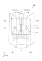
- FIG. 1 is an overall configuration diagram illustrating a configuration example of a welding system 1 according to an embodiment.
- the welding system 1 includes a welding device 10 for performing arc welding of a material to be welded, and a welding control device 20 for controlling welding conditions that define the movement of the welding device 10.
- the workpiece is an example of the workpiece.
- a welding device 10 shown in FIG. 1 includes a visual sensor 11 disposed in front of a welding part in a direction in which welding proceeds, a welding torch 12 having a TIG electrode, and a wire reel (not shown) for a filler wire 13. , A feeder (not shown) for feeding the filler wire 13, and a conduit cable 14 for supporting the filler wire 13.
- welding direction in which the welding proceeds is referred to as a “welding direction”
- the front in the welding direction is referred to as a “welding direction front”.
- the welding device 10 is mounted on a carriage 30 which is a carriage, and moves along with the carriage 30 along the rail 31.
- the rail 31 is installed in parallel with the welding direction.
- a pair of materials 50 to be welded are arranged with a root gap (not shown) interposed therebetween.
- one of the pair of materials to be welded 50 is arranged side by side on the far side of the drawing in the Y-axis direction.
- the root gap means a gap provided between a pair of materials to be welded.
- the welding direction is the direction of the X axis.
- a portion to be arc-welded is also referred to as a welding line.
- the direction in which the welding line of the present embodiment extends is parallel to the X axis.
- the Z axis corresponds to the vertical direction.
- the welding control device 20 processes an image captured by the visual sensor 11 and controls welding conditions of the welding device 10.
- the number of the visual sensor 11 is one, and the visual sensor for imaging the Uranami bead is not used.
- the welding control device 20 according to the present embodiment is configured as a computer that executes a program.
- the welding system 1 also includes a welding power source 40 for applying a voltage for generating the arc 16 to the electrodes, and a cooling water circulator (not shown) for circulating cooling water in the welding device 10.
- the welding system 1 may be provided with a teaching device 17 shown in FIG. 3 that can input welding conditions and manually operate each driving unit included in the welding device.
- the teaching device 17 may be installed inside the welding device 10 or may be installed outside the welding device 10. For example, the teaching device 17 may be installed on the carriage 30.
- a welding apparatus 10 shown in FIG. 1 includes a welding torch 12 for holding a TIG electrode and a conduit cable 14 for supporting a filler wire 13.
- the width direction of the groove which is orthogonal to the welding line parallel to the X axis and parallel to the surface of the workpiece, is also referred to as the left-right direction.
- the left-right direction corresponds to the Y-axis direction.
- the welding torch 12 is supported by a two-axis slider 15 that slides in a Y-axis direction orthogonal to a welding line parallel to the X-axis and in a Z-axis direction perpendicular to a plane defined by the X-axis and the Y-axis. I have.
- the welding device 10 includes a wire reel (not shown) that supplies the filler wire 13 to the workpiece 50.
- the welding torch 12 has a TIG electrode.
- An arc 16 is generated by applying a voltage from the welding power source 40 to the TIG electrode.
- one welding torch 12 is mounted on one carriage 30, but a plurality of welding torches 12 may be installed.
- the biaxial slider 15 supports the welding torch 12.
- the two-axis slider 15 has a horizontal slide part that slides the welding torch 12 in the Y-axis direction and a vertical slide part that slides the welding torch 12 in the Z-axis direction.
- the Y-axis direction coincides with the width direction of the groove parallel to the surface of the work.
- the horizontal slide portion slides so as to oscillate the welding torch 12.
- the Z-axis direction is the thickness direction of the workpiece 50.
- the horizontal slide portion and the vertical slide portion have a power transmission mechanism for transmitting the power of a motor (not shown), and the TIG electrode can be automatically slid in the Y-axis direction and the Z-axis direction, respectively. It is also possible to perform the weaving operation of the TIG electrode during welding.
- the distance between the welding torches 12, that is, the distance between the poles is preferably 50 to 400 mm. Heat input can be further suppressed by setting the distance between the electrodes to 50 mm or more. Further, by setting the distance between the electrodes to 400 mm or less, the appearance of the Uranami bead becomes better and the control of the welding conditions becomes easier.
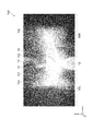
- FIG. 2 is a photograph showing an example of an image 100 obtained by capturing an area to be arc-welded by the visual sensor 11.
- the image 100 includes a fusion part 101 and a non-fusion part 102 around the fusion part 101.
- the melting portion 101 is formed by the molten filler wire 13.
- the fusion part 101 is also referred to as a fusion pool.
- the non-melted portion 102 is a groove portion of the welded material 50L located on the left side which is one side in the Y-axis direction of the root gap, and the welded material located on the right side which is the other side in the Y-axis direction of the root gap. Includes 50R groove, unfused root gap.
- the image 100 also includes the welding torch 12, the filler wire 13, and the conduit cable 14.
- the visual sensor 11 is arranged in a space between the conduit cable 14 supporting the filler wire 13 and the welding torch 12.
- the type of the visual sensor 11 is not particularly limited, but imaging can be performed over a wide wavelength range from an ultraviolet range to an infrared range, and a wider dynamic range is more preferable.
- the mounting position of the visual sensor 11 is fixed, and the range where the image 100 is captured by the visual sensor 11 is also approximately fixed.
- the range to be imaged may not be fixed, and the range to be imaged may be zoomed up, approached, or rocked, for example, in accordance with the weaving of the welding torch 12.
- the brightness of the arc 16 changes depending on the welding current.
- the luminance changes, it becomes difficult to recognize the shapes of the ends of the workpieces 50L and 50R that define the root gap and the tip of the molten pool in the image 100 captured by the visual sensor 11. Therefore, adjust the amount or wavelength of incident light per unit time by using a shutter speed, aperture, ND (Neutral Density) filter, band pass filter, short pass filter, long pass filter, etc. according to the welding current.
- a shutter speed, aperture, and ND filter affect the amount of light incident on the visual sensor 11
- the band-pass filter, short-pass filter, and long-pass filter affect the wavelength that the visual sensor 11 can obtain.
- the visual sensor 11 when the welding current is less than 200 A, if the amount of light obtained by the visual sensor 11 is within a range of 15 to 95% of a predetermined wavelength or wavelength range, that is, if the amount of incoming light is 100, the visual sensor 11 It is preferable to adjust the shutter speed, aperture, ND filter, and the like so that the obtained light quantity is transmitted at 15 to 95.
- the light amount obtained by the visual sensor 11 when the welding current is 200 A to 400 A, the light amount obtained by the visual sensor 11 is within a range of 5 to 90% of a predetermined wavelength or wavelength range, that is, when the incoming light amount is 100, the visual sensor 11 It is preferable to adjust the shutter speed, aperture, ND filter, etc., so that the amount of light transmitted by the lens is 5 to 90.
- the light amount obtained by the visual sensor 11 falls within a range of 0.5 to 85 with respect to a predetermined wavelength or wavelength range, that is, when the incoming light amount is 100, It is preferable to adjust the shutter speed, aperture, ND filter, and the like so that the light is transmitted at a light amount of 0.5 to 85. Further, it is preferable that the wavelength or the wavelength range incident on the visual sensor 11 is selected, for example, from the range of 500 to 1200 nm. More preferably, the amount of light obtained by the visual sensor 11 may be automatically adjusted in accordance with the control of the welding conditions. Further, an automatic adjustment may be performed such that the luminance value of an arbitrary part in the captured image 100 is measured and the luminance is controlled to a predetermined set luminance value. In addition, an arbitrary part is a molten pool, for example.
- the welding control device 20 (see FIG. 1) is provided separately from the welding device 10 (see FIG. 1) mounted on the carriage 30 (see FIG. 1). Control of the operation of each component constituting, control of welding conditions, processing, calculation or determination of an image captured by the visual sensor 11, and control of outputting a correction amount of the welding conditions are performed.
- the control of the operation of each part constituting the welding apparatus 10 includes, for example, sliding by a two-axis slider contributing to the weaving conditions, welding speed as the moving speed of the carriage 30, welding of the filler wire 13 in accordance with welding conditions set in advance. It controls operations such as the supply speed. Note that all controls may be performed by one control panel, but the welding control device 20 may be divided for each application. Further, the welding control device 20 includes a control for storing and outputting welding conditions.
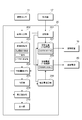
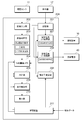
- FIG. 3 is a block diagram illustrating a configuration of each unit configuring the welding control device 20.
- the welding control device 20 includes a storage unit 201, an image input unit 202, an image processing unit 203, a feature amount extraction unit 204, a determination unit 205, a correction amount calculation unit 206, a welding device I / F processing unit 207, a welding power supply I / F. It includes a processing unit 208.
- the storage unit 201 stores, for example, welding conditions preset from the teaching device 17 or the like.
- the stored welding conditions include, for example, a welding current, an arc voltage, a welding speed, which is a moving speed of the carriage 30, a feed speed of the filler wire 13, a weaving condition, and conditions of the workpieces 50L and 50R.
- the weaving conditions include information such as an oscillation speed, an oscillation stop time, an oscillation width, an inversion height, and a shift amount.
- the conditions of the workpieces 50L and 50R include, for example, information such as plate thickness, groove shape, groove angle, and root gap.
- the image captured by the visual sensor 11 is input to the image input unit 202.
- the image processing unit 203 performs pre-processing for enhancing edges of the input image, extraction of a processed part, and the like.
- pre-edge enhancement processing for example, noise removal, sharpening, binarization, and the like are executed.
- extraction of the processing portion for example, extraction of a processing image, designation of a range, setting of a center point and a center axis, and the like are executed.
- the feature amount extraction unit 204 extracts a predetermined feature amount from the image 100 processed by the image processing unit 203.
- FIG. 4 is an explanatory diagram showing an example of feature amount extraction by the feature amount extraction unit 204 (see FIG. 3).
- the image 100 before extracting the feature amounts corresponds to the image 100 in FIG.
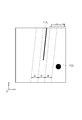
- the feature amount extraction unit 204 determines that the welding proceeds among the left edge line 111L that defines the left end of the root gap, the right edge line 111R that defines the right end of the root gap, and the fusion part 101 as the feature amount.
- the left end point 112L, which is the left end, and the right end point 112R, which is the right end, are extracted.
- the fusion part 101 is formed in the vicinity of the wall surface where the groove is formed in the materials to be welded 50L and 50R.
- the feature amount extraction unit 204 here is an example of the first detection unit and also an example of the second detection unit.
- the determination unit 205 determines the relationship between the position of the left end point 112L with respect to the left edge line 111L extracted by the feature amount extraction unit 204, and the right end point 112R with respect to the right edge line 111R extracted by the feature amount extraction unit 204. Is determined on the basis of the positional relationship of the back side bead formed on the back side.
- the determination unit 205 here is an example of a determination unit.
- 5A to 5D are explanatory diagrams illustrating an example of a determination method by the determination unit 205. 5A to 5D show the relationship between the left edge line 111L and the left end point 112L. The relationship between the right edge line 111R and the right end point 112R can be similarly determined.
- FIG. 3 determines the relationship between the position of the left end point 112L with respect to the left edge line 111L extracted by the feature amount extraction unit 204, and the right end point 112R with respect to the right edge line 111R extracted by the feature amount extraction unit 204.
- FIG. 5A is an explanatory diagram showing a case where the filler wire 13 (see FIG. 1) is melted in an appropriate amount.
- a broken line in FIG. 5A indicates a boundary position for determination using the left edge line 111L as a reference position.
- the distance between broken lines in the direction of the Y axis is D.
- the distance D is given in advance.
- the left end point 112L is located within 0.5D in the left-right direction with respect to the left edge line 111L.
- FIG. 5B is an explanatory diagram illustrating an example in which the filler wire 13 (see FIG. 1) is improperly melted.
- the left end point 112L is separated from the left edge line 111L by 1.5 D or more in the left direction.
- FIG. 5C is an explanatory diagram showing an example in which the determination of melting of the filler wire 13 (see FIG. 1) cannot be made.
- the left end point 112L is separated from the left edge line 111L in the left direction by 0.5 or more and less than 1.5D.
- FIG. 5D is an explanatory diagram showing an example in which the filler wire 13 (see FIG. 1) is improperly melted.
- FIG. 1 is an explanatory diagram illustrating an example in which the filler wire 13 (see FIG. 1) is improperly melted.
- the left end point 112L is separated from the left edge line 111L by 1.5 D or more in the right direction.
- the left direction is a direction away from the root gap
- the right direction is a direction approaching the center line of the root gap.
- the correction amount calculation unit 206 calculates a correction amount according to the result of the determination by the determination unit 205 (see FIG. 3). For example, when the relationship between the position of the left edge line 111L and the position of the left end point 112L is as shown in FIG. 5B or FIG. 5D, and the current state of the Uranami bead is determined to be defective, the correction amount calculation unit 206 determines the welding condition. Calculate the correction amount.
- the correction amount calculation unit 206 calculates the correction amount of the welding condition for one or more of the welding current, arc voltage, welding speed, wire feeding speed, electrode position, wire insertion position, and weaving condition, for example. Is preferred.
- the welding device I / F processing unit 207 (see FIG.
- the welding device I / F processing unit 207 generates a welding condition command to be output to the welding device 10 based on the input welding conditions and the correction amount.
- the welding power source I / F processing unit 208 generates a welding condition command to be output to the welding power source 40 based on the input welding conditions and the correction amount.
- the correction amount calculation unit 206, the welding device I / F processing unit 207, and the welding power supply I / F processing unit 208 are examples of a control unit that controls welding conditions.
- the display control unit 209 executes a process of displaying the result of the determination by the determination unit 205 on the screen of the display unit 210 (see FIG. 3). For example, the display control unit 209 displays the tip point of the molten pool extracted by the feature amount extraction unit 204 and a straight line that defines the end of the route gap on the image 100 captured by the visual sensor 11. For example, a left edge line 111L corresponding to the left end point 112L is superimposed on the image 100 and displayed. Alternatively, a right edge line 111R corresponding to the right end point 112R is displayed over the image 100. This display is displayed in parallel with the extraction of the feature amount.
- the display control unit 209 displays the result of the determination by the determination unit 205, that is, information indicating the quality of welding, in association with the left end point 112L and the right end point 112R.
- the results of the determination are displayed in chronological order for each of the left end point 112L and the right end point 112R.
- the display control unit 209 here is an example of a display control device and also an example of a display control unit.
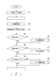
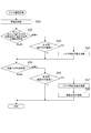
- FIG. 6 is a flowchart illustrating an example of a welding control method for the welding system 1 (refer to FIG. 1) in the present embodiment to obtain a good backside bead.
- the control shown in FIG. 6 is executed by welding control device 20 (see FIG. 1).
- the symbol S in the figure indicates a step.
- the welding control device 20 sets a processing mode (step 1).
- the welding conditions read from the teaching device 17 are set in the storage unit 201.
- the welding conditions are preferably, for example, one or more of a welding current, an arc voltage, a welding speed, a wire feeding speed, an electrode position, a wire insertion position, and a weaving condition.
- whether to control the welding speed, the welding current, and the wire feeding speed is set.
- “valid” or “invalid” for each control mode one or more of the “speed control mode”, “current control mode”, and “wire control mode” can be selected.
- the welding control device 20 instructs to start welding.
- the visual sensor 11 captures an image 100 including the fused portion 101 and the non-fused portion 102 near the arc, and outputs image data corresponding to the captured image 100.
- This image data is input to the image input unit 202 of the welding control device 20 (Step 2). That is, a welding image is captured.
- the image processing unit 203 cuts out a predetermined range from the input image as a processed image, and executes pre-edge enhancement processing such as noise removal, sharpening, and binarization of the cut out image.
- FIG. 7 is an explanatory diagram illustrating an example of a range cut out as a processed image. Needless to say, the cutout example shown in FIG. 7 is an example.
- two processing ranges 120L and 120R including each of the two end points of the fusion zone 101 are cut out.
- the processing range 120L includes the left end point 112L of the fusion zone 101 and the wall surface of the groove portion of the left welded material 50L.
- the processing range 120R includes the right end point 112R of the fusion zone 101 and the wall surface of the groove portion of the right welded material 50R.
- the processing ranges 120L and 120R are cut out based on reference points PL and PR specified in advance.
- Positions within the processing range 120L are given with reference to the reference point PL, and positions within the processing range 120R are given with reference to the reference point PR.
- the processing ranges 120L and 120R may be fixedly determined with reference to predetermined reference points PL and PR, but the image processing unit 203 sets the processing ranges 120L and 120R with a change in the input image 100.
- the area may be changed each time.
- the tip of the oscillating welding torch 12 may be used as a reference point, and the processing range may be changed according to the oscillating motion.
- the feature amount extraction unit 204 extracts a feature amount by image processing (Step 3).
- the feature amount extraction unit 204 includes a left edge line 111L corresponding to the left end of the root gap, a right edge line 111R corresponding to the right end of the root gap, a left end point 112L which is a left end of the molten pool, The right end point 112R, which is the right end of the molten pool, is extracted as a feature value.
- the left edge line 111L and the right edge line 111R are extracted by performing a Hough transform on the binarized image.
- the processing ranges 120L and 120R are each subjected to Hough transform, and the longest straight line among a plurality of straight lines detected for each of the processing ranges 120L and 120R is defined as a left edge line 111L and a right edge line 111R. I do.
- x and y are coordinate values for the reference points PL and PR, a is the slope, and b is the intercept.
- the feature amount extraction unit 204 detects the arc shape that is the tip of the molten pool included in the processing range 120L as the left end point 112L, and detects the arc shape that is the tip of the molten pool included in the processing range 120R as the right end point 112R. To detect.
- Information on the feature amounts extracted from the image 100 corresponding to the processing ranges 120L and 120R is provided to the determination unit 205.
- the determination unit 205 determines the positional relationship between the left end point 112L and the left edge line 111L of the root gap, or the positional relationship between the right end point 112R and the right edge line 111R of the root gap, as shown in FIGS. 5A to 5D. However, if any one of the positional relations indicates defective welding, the correction amount calculation unit 206 calculates the correction amount of the welding condition set in advance.
- the setting of the determination unit 205 and the correction amount calculation unit 206 is valid or invalid in each of the speed control mode (step 4), the current control mode (step 6), and the wire control mode (step 8). Is determined. If the setting of the speed control mode is valid (if valid in step 4), the determination unit 205 and the correction amount calculation unit 206 control the welding speed (step 5). Thereafter, the determination unit 205 and the correction amount calculation unit 206 proceed to Step 6. If the setting of the speed control mode is invalid (if invalid in step 4), the determination unit 205 and the correction amount calculation unit 206 determine whether the setting of the current control mode is valid (step 6).
- the determination unit 205 and the correction amount calculation unit 206 control the welding current (step 7). Thereafter, the determination unit 205 and the correction amount calculation unit 206 proceed to Step 8. If the setting of the current control mode is invalid (if invalid in step 6), the determination unit 205 and the correction amount calculation unit 206 determine whether the setting of the wire control mode is valid (step 8). If the setting of the wire control mode is valid (if valid in step 8), the determination unit 205 and the correction amount calculation unit 206 control the wire speed (step 9). Thereafter, the determination unit 205 and the correction amount calculation unit 206 return to Step 2.
- step 8 If the setting of the wire control mode is invalid (if invalid in step 8), the determination unit 205 and the correction amount calculation unit 206 return to step 2. This loop processing is repeated while welding of the workpieces 50L and 50R is being performed.
- the details of the control of the welding speed in step 5, the control of the welding current in step 7, and the control of the wire speed in step 9 will be described.
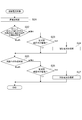
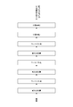
- FIG. 8 is a flowchart illustrating details of control executed when the setting of the speed control mode is valid.
- the determination unit 205 determines the image 100 (Step 11).
- the determination unit 205 determines the relationship between the position of the tip point of the molten pool and the edge line of the extracted root gap (step 12). Specifically, it is determined whether or not the extracted left end point 112L satisfies the relationship shown in FIG. 5A with respect to the left edge line 111L of the root gap. In other words, it is determined whether the relative distance between the left end point 112L and the left edge line 111L of the route gap is within a predetermined range or outside the predetermined range.
- the determination unit 205 calculates the distance LL between the left end point 112L and the left edge line 111L of the root gap, or the distance LR between the right end point 112R and the right edge line 111R of the root gap. Note that both the distances LL and LR are calculated at one time, depending on the position in the image of the swingingly driven welding torch 12 (see FIG. 1). Hereinafter, the distance LL and the distance LR are also collectively referred to as a distance L.
- the coordinates of the left end point 112L or the right end point 112R, which are the tip points of the molten pool, are represented as (X1, Y1), and a linear function that gives the left edge line 111L or the right edge line 111R of the root gap is represented.
- x ay + b
- the distance L is expressed by the following equation.
- L abs (X1-aY1-b) / ⁇ (X1 2 + Y1 2 ) (Formula 1)
- abs () is a function that gives the absolute value of the numerical value in parentheses.
- a is the inclination and b is the intercept.
- the determination unit 205 determines that the backside bead is good. On the other hand, when the distance L is out of the predetermined range, the determination unit 205 determines that the Uranami bead is defective. If it is determined in step 12 that the area is out of the range, that is, it is determined to be defective, the determination unit 205 further determines whether the area is out of the range for a predetermined period of time (step 13). If a negative result is obtained in step 13, the determination unit 205 determines that the cause of the defect is simply a disturbance, and proceeds to step 15. In this case, the welding speed is maintained.
- the correction amount calculation unit 206 calculates the correction amount so as to increase or decrease the welding speed (Step 14).
- the correction amount is calculated so that the welding speed is increased when the determination is made as shown in FIG. 5B in the determination in step 12, and the welding speed is decreased when the determination is made as shown in FIG. 5D.
- the corrected welding speed is output to the welding device 10 as a welding condition command.
- the welding speed is the moving speed of the carriage 30.
- the correction amount of the welding speed is preferably calculated based on the relationship between the distance between the leading end point of the molten pool and the edge line of the route gap, and the duration during which the distance is determined to be defective.
- the determination unit 205 further determines the shape of the molten pool (Step 15).
- the determination of the shape of the molten pool is optional. By controlling the welding speed based on the relationship between the tip point of the molten pool and the edge line of the root gap, a good Uranami bead can be maintained, but the amount of deposition also changes as the welding speed increases or decreases.
- the determination unit 205 in the present embodiment acquires information such as the width, area, and volume of the molten pool from the image 100 of the processing range 120L or 120R, and detects the shape of the molten pool from the acquired information.
- the determination unit 205 compares the detected shape of the molten pool with a preset ideal shape, or evaluates a difference between the ideal shape and the detected shape of the molten pool. It is determined whether the shape is within or outside a predetermined range (step 15).
- the determination unit 205 determines whether or not the out-of-range continues for a predetermined period of time (step 16). If a negative result is obtained in step 16, the determination unit 205 determines that the cause of the determination that the shape is out of the range is simply a disturbance, and ends the process while maintaining the current welding speed. On the other hand, if a positive result is obtained in step 16, the determination unit 205 determines that the shape is continuously out of the range. In the case of the present embodiment, the correction amount calculation unit 206 calculates the correction amount so as to increase or decrease the welding speed (Step 17).
- step 14 if it is determined in step 14 that the welding speed has been increased too much and the amount of deposition has increased beyond the specified range, the welding speed is reduced and adjustment is made so that the shape of the molten pool approaches an ideal shape.
- a welding speed that takes into account both the correction amounts of step 14 and step 17 is output to the welding device 10 as a welding condition command.
- the correction amount of the welding speed takes into account not only the relationship between the distance between the tip point of the molten pool and the edge line of the root gap, the duration during which the distance is determined to be defective, but also changes in the shape of the molten pool. Is preferably calculated.
- FIG. 9 is a flowchart illustrating details of control executed when the setting of the current control mode is valid.
- the determination unit 205 determines the image 100 (Step 21).
- the determination unit 205 determines the relationship between the position of the tip point of the molten pool and the edge line of the extracted root gap (step 22). Specifically, it is determined whether or not the extracted left end point 112L satisfies the relationship shown in FIG. 5A with respect to the left edge line 111L. In other words, it is determined whether the relative distance between the left end point 112L and the left edge line 111L is within a predetermined range or outside the range.
- the determination unit 205 calculates the distance LL between the left end point 112L and the left edge line 111L, or the distance LR between the right end point 112R and the right edge line 111R. Note that both the distances LL and LR are calculated at one time, depending on the position in the image of the swingingly driven welding torch 12 (see FIG. 1).
- the distance LL and the distance LR are also collectively referred to as a distance L.
- the distance L here is also calculated by using the above-described equation 1.
- the determination unit 205 determines that the backside bead is good.
- the determination unit 205 determines that the Uranami bead is defective.
- the determination unit 205 determines whether or not the out-of-range continues for a predetermined time (step 23). If a negative result is obtained in step 23, the determination unit 205 determines that the cause of the defect is simply a disturbance, and proceeds to step 26. In this case, the welding speed is maintained. On the other hand, when a positive result is obtained in step 23, the determination unit 205 continuously determines that the backside bead is defective.
- the correction amount calculation unit 206 calculates the correction amount so as to increase or decrease the welding current (Step 24). For example, the correction amount is calculated so that the welding current is decreased when the determination is made as shown in FIG.
- the welding current is increased when the determination is made as shown in FIG. 5D.
- the welding current may be determined based on, for example, an average pulse current. Since the average pulse current changes depending on parameters such as a peak current value, a base current value, a peak period or a base period, one or more of these parameters are determined in advance as parameters for increasing or decreasing the average pulse current. Is preferred.
- the corrected welding current is output to the welding power source 40 as a welding condition command. As described above, it is preferable that the correction amount of the welding current is calculated based on the relationship between the distance between the leading end point of the molten pool and the edge line of the route gap, and the duration during which the distance is determined to be defective.
- the determination unit 205 further determines the shape of the molten pool (Step 25).
- the execution of the determination of the shape of the molten pool is optional.
- the determination unit 205 in the present embodiment acquires information such as the width, area, and volume of the molten pool from the image 100 of the processing range 120L or 120R, and detects the shape of the molten pool from the acquired information. Further, the determination unit 205 compares the detected molten pool shape with a preset ideal shape or evaluates a difference between the detected molten pool shape and a predetermined ideal shape. (Step 25).
- the determination unit 205 determines whether or not the out of range continues for a predetermined period of time (step 26). If a negative result is obtained in step 26, the determination unit 205 determines that the cause of the determination that the shape is out of the range is a simple disturbance, and ends the process while maintaining the current welding current and pulse current. On the other hand, when a positive result is obtained in step 26, the determination unit 205 determines that the shape is continuously out of the range. In the case of the present embodiment, the correction amount calculation unit 206 calculates the correction amount so as to increase or decrease the welding current (Step 27).
- the welding current taking into account the correction amounts of both Step 24 and Step 27 is output to the welding power source 40 as a welding condition command.
- the correction amount of the welding current takes into account not only the relationship between the distance between the tip point of the molten pool and the edge line of the root gap, the duration during which the distance is determined to be defective, but also changes in the shape of the molten pool. Is preferably calculated.
- FIG. 10 is a flowchart illustrating details of control performed when the setting of the wire control mode is valid.
- the determination unit 205 determines the image 100 (Step 31).
- the determination unit 205 determines the relationship between the position of the tip point of the molten pool and the edge line of the extracted root gap (step 32). Specifically, it is determined whether or not the extracted left end point 112L satisfies the relationship shown in FIG. 5A with respect to the left edge line 111L. In other words, it is determined whether the relative distance between the left end point 112L and the left edge line 111L is within a predetermined range or outside the range.
- the determination unit 205 calculates the distance LL between the left end point 112L and the left edge line 111L, or the distance LR between the right end point 112R and the right edge line 111R. Note that both the distances LL and LR are calculated at one time, depending on the position in the image of the swingingly driven welding torch 12 (see FIG. 1).
- the distance LL and the distance LR are also collectively referred to as a distance L.
- the distance L here is also calculated by using the above-described equation 1.
- the determination unit 205 determines that the backside bead is good.
- the determination unit 205 determines that the Uranami bead is defective.
- the determination unit 205 determines whether or not the out-of-range continues for a predetermined time (step 33). When a negative result is obtained in step 33, the determination unit 205 determines that the cause of the defect is simply a disturbance, and proceeds to step 35. In this case, the welding speed is maintained. On the other hand, when a positive result is obtained in step 33, the determination unit 205 continuously determines that the back side bead is defective. In the case of the present embodiment, the correction amount calculation unit 206 calculates the correction amount so as to increase or decrease the wire feeding speed (Step 34).
- the correction amount is calculated so that the wire feeding speed is decreased when the determination is made as shown in FIG. 5B in the determination in step 33, and the wire feeding speed is increased when the determination is made as shown in FIG. 5D.
- the corrected wire feed speed is output to the welding device 10 as a welding condition command.
- the correction amount of the wire feeding speed is calculated based on the relationship between the distance between the leading end point of the molten pool and the edge line of the route gap, and the duration during which the distance is determined to be defective.
- the determination unit 205 further determines the shape of the molten pool (Step 35).
- the execution of the determination of the shape of the molten pool is optional.
- the determination unit 205 in the present embodiment acquires information such as the width, area, and volume of the molten pool from the image 100 of the processing range 120L or 120R, and detects the shape of the molten pool from the acquired information. Further, the determination unit 205 compares the detected molten pool shape with a preset ideal shape or evaluates a difference between the detected molten pool shape and a predetermined ideal shape. (Step 35).
- the determination unit 205 determines whether the out-of-range is continued for a predetermined time (step 36). If a negative result is obtained in step 36, the determination unit 205 determines that the cause of the determination that the shape is out of the range is simply a disturbance, and ends the process while maintaining the current welding current and pulse current. On the other hand, when a positive result is obtained in step 36, the determination unit 205 determines that the shape is continuously out of the range. In the case of the present embodiment, the correction amount calculation unit 206 calculates the correction amount so as to increase or decrease the wire feeding speed (step 37).
- the correction amount calculation unit 206 calculates a correction amount so as to increase or decrease the welding current (step 38).
- the wire feed speed taking into account both the correction amounts of step 34 and step 37 is output to the welding device 10 as a welding condition command.
- the correction amount of the wire feed speed is determined not only by the relationship between the distance between the tip point of the molten pool and the edge line of the route gap, the duration during which the distance is determined to be defective, but also by the change in the shape of the molten pool. It is preferable that the calculation be performed in consideration of the addition.
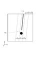
- FIG. 11A is a diagram illustrating an example of a screen in which a left edge line 111L corresponding to a left end point 112L extracted by the feature amount extraction unit 204 is superimposed on the image 100 captured by the visual sensor 11 and displayed.
- the left end point 112L is represented by a circular symbol
- the extracted left edge line 111L is represented by a straight line.
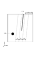
- FIG. 11B is a diagram illustrating an example of a screen in which a right edge line 111R corresponding to the right end point 112R extracted by the feature amount extraction unit 204 (see FIG. 3) is superimposed on the image 100 captured by the visual sensor 11 and displayed. It is.
- the right end point 112R is represented by a circular symbol
- the extracted right edge line 111R is represented by a straight line.
- the display colors of the left end point 112L and the right end point 112R and the display colors of the left edge line 111L and the right edge line 111R in FIGS. 11A and 11B are arbitrary.
- the brightness of the extracted feature points may be higher than that of the surrounding image, or the display color may be a color close to the opposite color of the surrounding image, so that the worker can easily confirm the feature point.
- the operator can visually check whether or not the extraction has been correctly performed. Will be possible.
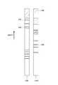
- FIG. 12 is an explanatory diagram illustrating an example of a screen that displays the result of the determination by the determination unit 205 in association with the left edge and the right edge of the root gap.
- a band-shaped display column 130L located on the left side shows the determination result corresponding to the left edge of the root gap
- a band-shaped display column 130R located on the right side shows the determination result corresponding to the right edge of the root gap. Is shown.
- a line segment is shown at the time when the determination result is output, and a period during which the determination result is not output is blank.
- the quality of the determination result is indicated by the difference in the color of the line segment. For example, blue is used when it is determined that a good Uranami bead is formed. In this case, the edge point of the leading end point and the root gap satisfies the relationship of FIG. 5A. The red color is used when it is determined that the formation of the Uranami bead is defective. In this case, the tip point and the edge line of the root gap satisfy the relationship shown in FIG. 5B or 5D. Yellow is used when it is determined that the quality of the Uranami bead is unknown. In this case, the tip point and the edge line of the root gap satisfy the relationship shown in FIG. 5C. In the case of FIG. 12, the latest determination result is displayed at the top of each of the display columns 130L and 130R. Therefore, the bottom of each of the display columns 130L and 130R corresponds to the information at the time when the displayed determination result is obtained at the oldest time.
- FIG. 13 is an explanatory diagram illustrating a configuration example of a welding control device 20A having a learning device 211.
- the parts corresponding to those in FIG. The difference between the welding control device 20A illustrated in FIG. 13 and the welding control device 20 illustrated in FIG. This is the point given to the quantity calculation unit 206.
- the feature amount extraction unit 204 applies a learning model generated using, for example, a recurrent connection type deep neural network: DNN to the image 100 captured by the visual sensor 11 to determine the tip point of the molten pool.
- the coordinates (X1, Y1) to be given and a linear function giving the edge line of the root gap are extracted.
- the learning model here is an example of the first model and the second model. Specifically, the values of X1 and Y1 that give the coordinates, and the values of the slope a and the intercept b of the linear function expressed by Equation 1 are determined.
- FIG. 14 is an explanatory diagram showing a process of the feature amount extraction unit 204 from applying the image input from the visual sensor 11 to the learning model and extracting the feature amount. As shown in FIG.
- the feature amount extraction unit 204 calculates the number of matching of features over the entire image 100 and performs a convolution layer for extracting a feature portion of the image and a noise process for enhancing the extracted feature portion.
- the pooling layer to be performed is repeated, and the entire combined layer that finally combines the processing results is executed, and the coordinate values X1, Y1, the slope a, and the intercept b are output.
- the determination unit 205 and the correction amount calculation unit 206 may apply a learning model generated using, for example, a regression-coupled DNN to input data, and output a determination result and a correction amount for the extracted feature amount.
- Teacher data may be prepared for the determination of the determination unit 205 and for the calculation of the correction amount calculation unit 206 in the same procedure as that of the feature amount extraction unit 204 described above. That is, a plurality of sets of relations of output values to input data such as image data when welding a workpiece under various welding conditions may be prepared as teacher data.
- p1 is a state where a good backside bead corresponding to FIG. 5A is generated, that is, “melted”.
- p2 is a state in which it is unknown whether or not a good backside bead corresponding to FIG. 5C has been generated, that is, a state in which "it cannot be determined whether or not it is melted or not melted”.
- p3 is a state in which a bad Uranami bead corresponding to FIG. 5B and FIG. 5D is generated, that is, “unmelted”.
- p4 is a state in which a wire or the like reflected in the image 100 is in the way and the positional relationship cannot be determined. p4 corresponds to the blank period in FIG.
- the learning device 211 given the teacher data designs a regression-coupled DNN that outputs four types of outputs p1 to p4 with respect to the image data captured under various welding conditions. By learning additional image data, a regression-coupled DNN learning model is generated. The generated learning model is provided to the determination unit 205.
- FIG. 15 is an explanatory diagram showing a processing procedure until the determination unit 205 applies an image input from the visual sensor 11 to a learning model and outputs any of four types of determination results. As illustrated in FIG. 15, the determination unit 205 calculates the number of matching cases of the feature over the entire image 100 and extracts a feature portion of the image, and a pooling process that performs noise processing for enhancing the extracted feature portion. The layers are repeated, and finally all the combined layers for combining the processing results are executed, and any one of p1 to p4 is output.
- the correction amount may be output in accordance with the relationship between the four types of outputs p1 to p4 and predetermined welding conditions.
- the "not melted" state may be further classified into “slightly melted” and “not melted at all”, and a correction amount corresponding to each classification may be output.
- a value that reduces the welding speed by 5 cm per minute may be set as the correction amount.
- a value that reduces the welding speed by 10 cm per minute may be set as the correction amount.
- DNN is used for generating a learning model, but it goes without saying that generation of a learning model is not limited to DNN.
- an edge line of a root gap as a feature amount is extracted by image processing and an example in which the edge line is extracted using a learning model have been described.
- measurement may be performed while welding.
- a sensor for measuring the position of the edge line of the root gap on the front side in the welding direction relative to the welding portion is provided on the carriage 30, and the measurement values sequentially output from the sensor as the welding progresses are displayed on the left edge line 111L and the right edge line. What is necessary is just to give to the determination part 205 as 111R.
- the sensor may be attached to any position of the carriage 30 as long as the sensor is located ahead of the welding site in the welding direction and can measure the root gap.
- the sensor is an example of a second detection unit.
- the feature quantity extraction unit 204 may extract only the left end point 112L and the right end point 112R, which are the tip points of the molten pool, from the image 100 and provide the same to the determination unit 205.
- the feature amount extraction unit 204 functions only as a first detection unit.
- the learning model generated by the learning device 211 may be applied to the feature amount extraction unit 204 and the like.
- the learning model here is an example of a first model.
Landscapes
- Engineering & Computer Science (AREA)
- Physics & Mathematics (AREA)
- Plasma & Fusion (AREA)
- Mechanical Engineering (AREA)
- Theoretical Computer Science (AREA)
- Butt Welding And Welding Of Specific Article (AREA)
- Arc Welding In General (AREA)
- Arc Welding Control (AREA)
- Numerical Control (AREA)
Abstract
Priority Applications (4)
| Application Number | Priority Date | Filing Date | Title |
|---|---|---|---|
| EP19852212.0A EP3842173A4 (fr) | 2018-08-21 | 2019-08-07 | Dispositif de commande de soudage, dispositif de commande d'affichage, système de soudage, procédé de commande de soudage et programme |
| KR1020217004215A KR102439381B1 (ko) | 2018-08-21 | 2019-08-07 | 용접 제어 장치, 표시 제어 장치, 용접 시스템, 용접 제어 방법 및 프로그램 |
| US17/266,861 US12275099B2 (en) | 2018-08-21 | 2019-08-07 | Welding control device, display control device, welding system, welding control method, and program |
| CN201980054716.0A CN112584957B (zh) | 2018-08-21 | 2019-08-07 | 焊接控制装置、显示控制装置、焊接系统、焊接控制方法以及程序 |
Applications Claiming Priority (2)
| Application Number | Priority Date | Filing Date | Title |
|---|---|---|---|
| JP2018154606A JP7075311B2 (ja) | 2018-08-21 | 2018-08-21 | 溶接制御装置、表示制御装置、溶接システム、溶接制御方法及びプログラム |
| JP2018-154606 | 2018-08-21 |
Publications (1)
| Publication Number | Publication Date |
|---|---|
| WO2020039948A1 true WO2020039948A1 (fr) | 2020-02-27 |
Family
ID=69593129
Family Applications (1)
| Application Number | Title | Priority Date | Filing Date |
|---|---|---|---|
| PCT/JP2019/031251 Ceased WO2020039948A1 (fr) | 2018-08-21 | 2019-08-07 | Dispositif de commande de soudage, dispositif de commande d'affichage, système de soudage, procédé de commande de soudage et programme |
Country Status (6)
| Country | Link |
|---|---|
| US (1) | US12275099B2 (fr) |
| EP (1) | EP3842173A4 (fr) |
| JP (1) | JP7075311B2 (fr) |
| KR (1) | KR102439381B1 (fr) |
| CN (1) | CN112584957B (fr) |
| WO (1) | WO2020039948A1 (fr) |
Cited By (3)
| Publication number | Priority date | Publication date | Assignee | Title |
|---|---|---|---|---|
| JP2021171810A (ja) * | 2020-04-30 | 2021-11-01 | 株式会社神戸製鋼所 | 溶接情報の学習モデル生成方法、学習モデル、プログラム及び溶接システム |
| CN115175782A (zh) * | 2020-03-06 | 2022-10-11 | 三菱电机株式会社 | 数控装置及附加制造装置的控制方法 |
| CN116787027A (zh) * | 2022-03-18 | 2023-09-22 | 中联重科股份有限公司 | 用于工件装配的装置及方法 |
Families Citing this family (9)
| Publication number | Priority date | Publication date | Assignee | Title |
|---|---|---|---|---|
| KR102266453B1 (ko) * | 2020-09-18 | 2021-06-17 | 한국광기술원 | 용접 공정에서의 객체 트래킹 장치 및 방법 |
| JP7594403B2 (ja) * | 2020-10-02 | 2024-12-04 | 株式会社東芝 | 学習モデルの生成方法、学習済みモデル、画像処理方法、画像処理システム、及び溶接システム |
| JP7514169B2 (ja) * | 2020-11-16 | 2024-07-10 | 日立Geニュークリア・エナジー株式会社 | 溶接支援装置、および、溶接支援方法 |
| JP7566640B2 (ja) * | 2021-01-04 | 2024-10-15 | 株式会社東芝 | 処理装置、溶接システム、処理方法、プログラム、及び記憶媒体 |
| WO2022181060A1 (fr) * | 2021-02-26 | 2022-09-01 | パナソニックIpマネジメント株式会社 | Procédé et dispositif de détermination d'un état de traitement par laser |
| JP7677092B2 (ja) * | 2021-09-24 | 2025-05-15 | トヨタ自動車株式会社 | 学習モデル生成方法、検査システム及び学習モデル生成プログラム |
| KR102699999B1 (ko) * | 2021-12-29 | 2024-08-28 | (주) 토탈소프트뱅크 | 실시간 용접 위빙 궤적 분석 처리 장치 |
| WO2024122231A1 (fr) | 2022-12-07 | 2024-06-13 | 住友重機械工業株式会社 | Dispositif de soudage et programme de commande de soudage |
| CN117206638B (zh) * | 2023-09-19 | 2025-04-01 | 中国核工业第五建设有限公司 | 一种复合tig焊接方法 |
Citations (5)
| Publication number | Priority date | Publication date | Assignee | Title |
|---|---|---|---|---|
| JPH0220661A (ja) * | 1988-07-11 | 1990-01-24 | Nkk Corp | 円筒容器の自動溶接法 |
| JP2006281282A (ja) | 2005-04-01 | 2006-10-19 | Jfe Koken Corp | 溶接制御方法及び溶接装置 |
| JP2008246536A (ja) * | 2007-03-30 | 2008-10-16 | Ihi Corp | 溶接状況解析装置及び方法 |
| JP2015098031A (ja) | 2013-11-18 | 2015-05-28 | 三菱日立パワーシステムズ株式会社 | 溶接方法および装置 |
| JP2018154606A (ja) | 2017-03-21 | 2018-10-04 | Well Stone 有限会社 | 血圧降下剤の製造方法、及び、血圧降下剤 |
Family Cites Families (8)
| Publication number | Priority date | Publication date | Assignee | Title |
|---|---|---|---|---|
| JPH05111767A (ja) * | 1991-10-18 | 1993-05-07 | Kawasaki Steel Corp | 溶接条件設定装置 |
| JP3464902B2 (ja) * | 1998-01-26 | 2003-11-10 | 日鐵住金溶接工業株式会社 | 開先倣い装置 |
| JP2005081419A (ja) * | 2003-09-10 | 2005-03-31 | Nippon Steel Corp | Tigアーク溶接の自動制御方法 |
| JP2006247673A (ja) * | 2005-03-09 | 2006-09-21 | Hitachi Ltd | 配管溶接施工方法 |
| JP2007185700A (ja) * | 2006-01-16 | 2007-07-26 | Jfe Koken Corp | 溶接制御方法及び溶接装置 |
| JP2009195977A (ja) * | 2008-02-25 | 2009-09-03 | Jfe Engineering Corp | 自動溶接制御方法及び自動溶接装置 |
| US20160193681A1 (en) * | 2015-01-07 | 2016-07-07 | Illinois Tool Works Inc. | Synchronized image capture for welding machine vision |
| BR102015030119B1 (pt) * | 2015-12-01 | 2021-04-13 | Vale S/A | Aparelho configurado para soldagem mig/mag automatizada de passes de raiz e método de soldagem mig/mag automatizada |
-
2018
- 2018-08-21 JP JP2018154606A patent/JP7075311B2/ja active Active
-
2019
- 2019-08-07 KR KR1020217004215A patent/KR102439381B1/ko active Active
- 2019-08-07 CN CN201980054716.0A patent/CN112584957B/zh active Active
- 2019-08-07 WO PCT/JP2019/031251 patent/WO2020039948A1/fr not_active Ceased
- 2019-08-07 EP EP19852212.0A patent/EP3842173A4/fr not_active Withdrawn
- 2019-08-07 US US17/266,861 patent/US12275099B2/en active Active
Patent Citations (5)
| Publication number | Priority date | Publication date | Assignee | Title |
|---|---|---|---|---|
| JPH0220661A (ja) * | 1988-07-11 | 1990-01-24 | Nkk Corp | 円筒容器の自動溶接法 |
| JP2006281282A (ja) | 2005-04-01 | 2006-10-19 | Jfe Koken Corp | 溶接制御方法及び溶接装置 |
| JP2008246536A (ja) * | 2007-03-30 | 2008-10-16 | Ihi Corp | 溶接状況解析装置及び方法 |
| JP2015098031A (ja) | 2013-11-18 | 2015-05-28 | 三菱日立パワーシステムズ株式会社 | 溶接方法および装置 |
| JP2018154606A (ja) | 2017-03-21 | 2018-10-04 | Well Stone 有限会社 | 血圧降下剤の製造方法、及び、血圧降下剤 |
Non-Patent Citations (1)
| Title |
|---|
| See also references of EP3842173A4 |
Cited By (9)
| Publication number | Priority date | Publication date | Assignee | Title |
|---|---|---|---|---|
| CN115175782A (zh) * | 2020-03-06 | 2022-10-11 | 三菱电机株式会社 | 数控装置及附加制造装置的控制方法 |
| JP2021171810A (ja) * | 2020-04-30 | 2021-11-01 | 株式会社神戸製鋼所 | 溶接情報の学習モデル生成方法、学習モデル、プログラム及び溶接システム |
| WO2021220698A1 (fr) * | 2020-04-30 | 2021-11-04 | 株式会社神戸製鋼所 | Procédé de génération de modèle d'apprentissage, modèle d'apprentissage et programme pour des informations de soudage, et système de soudage |
| CN115151365A (zh) * | 2020-04-30 | 2022-10-04 | 株式会社神户制钢所 | 焊接信息的学习模型生成方法、学习模型、程序以及焊接系统 |
| KR20220158266A (ko) * | 2020-04-30 | 2022-11-30 | 가부시키가이샤 고베 세이코쇼 | 용접 정보의 학습 모델 생성 방법, 학습 모델, 프로그램 및 용접 시스템 |
| EP4063056A4 (fr) * | 2020-04-30 | 2023-12-27 | Kabushiki Kaisha Kobe Seiko Sho (Kobe Steel, Ltd.) | Procédé de génération de modèle d'apprentissage, modèle d'apprentissage et programme pour des informations de soudage, et système de soudage |
| JP7551327B2 (ja) | 2020-04-30 | 2024-09-17 | 株式会社神戸製鋼所 | 溶接情報の学習モデル生成方法、学習モデル、プログラム及び溶接システム |
| KR102809291B1 (ko) * | 2020-04-30 | 2025-05-19 | 가부시키가이샤 고베 세이코쇼 | 용접 정보의 학습 모델 생성 방법, 학습 모델, 프로그램 및 용접 시스템 |
| CN116787027A (zh) * | 2022-03-18 | 2023-09-22 | 中联重科股份有限公司 | 用于工件装配的装置及方法 |
Also Published As
| Publication number | Publication date |
|---|---|
| EP3842173A4 (fr) | 2022-05-18 |
| EP3842173A1 (fr) | 2021-06-30 |
| JP2020028889A (ja) | 2020-02-27 |
| CN112584957B (zh) | 2022-08-30 |
| CN112584957A (zh) | 2021-03-30 |
| JP7075311B2 (ja) | 2022-05-25 |
| US12275099B2 (en) | 2025-04-15 |
| US20210291288A1 (en) | 2021-09-23 |
| KR20210031493A (ko) | 2021-03-19 |
| KR102439381B1 (ko) | 2022-09-01 |
Similar Documents
| Publication | Publication Date | Title |
|---|---|---|
| WO2020039948A1 (fr) | Dispositif de commande de soudage, dispositif de commande d'affichage, système de soudage, procédé de commande de soudage et programme | |
| US11524368B2 (en) | Augmented vision system with active welder guidance | |
| US20110006047A1 (en) | Method and system for monitoring and characterizing the creation of a manual weld | |
| US20220331912A1 (en) | Automatic welding system, automatic welding method, welding assistance device, and program | |
| KR20180118540A (ko) | 온도 검출기를 이용한 용접 방법 및 시스템 | |
| KR20120100967A (ko) | 개선의 절단 장치 및 절단 방법 | |
| JP6052798B2 (ja) | 自動溶接機の異常監視装置 | |
| WO2023068055A1 (fr) | Procédé et dispositif de surveillance de soudage, et procédé et dispositif de moulage de stratifié | |
| JP2023095820A (ja) | 学習モデルの生成方法、制御装置、学習モデル、溶接システム、およびプログラム | |
| CN101309774A (zh) | 借助摆动电极的窄间隙埋弧焊接方法 | |
| KR20240110973A (ko) | 자동 용접의 용접 제어 방법, 제어 장치, 용접 시스템, 프로그램, 및 용접 방법 | |
| KR20140082156A (ko) | 광흐름을 이용한 잠호 용접 시스템의 이동거리 측정장치 및 측정방법 | |
| JP4154153B2 (ja) | アーク画像の取込方法 | |
| JP7751428B2 (ja) | 溶接計測システムおよび溶接計測方法 | |
| CN111014891A (zh) | 一种焊缝跟踪处理系统 | |
| CN119747809A (zh) | 一种基于熔池相机实时监测tig焊接质量的方法及焊接设备 | |
| JP4117526B2 (ja) | X開先継手の多層盛溶接方法 | |
| JP2005334904A (ja) | 自動倣い溶接制御方法及び装置 | |
| JP2895289B2 (ja) | 溶接自動倣い装置 | |
| JP4701655B2 (ja) | 溶接制御方法及び溶接装置 | |
| US20250289073A1 (en) | Welding device and non-transitory computer readable medium storing welding control program | |
| KR100737680B1 (ko) | 실링비드 및 본 용접의 동시수행이 가능한 자동용접장치및 이를 이용한 자동용접방법 | |
| JP3051632B2 (ja) | 溶接部材開先倣い制御方法 | |
| Liu et al. | Research on automatic welding system for oil and gas pipeline based on laser tracking technology | |
| JP2026054180A (ja) | 溶接制御方法、溶接システム、溶接制御プログラム、及び多層盛溶接方法 |
Legal Events
| Date | Code | Title | Description |
|---|---|---|---|
| 121 | Ep: the epo has been informed by wipo that ep was designated in this application |
Ref document number: 19852212 Country of ref document: EP Kind code of ref document: A1 |
|
| ENP | Entry into the national phase |
Ref document number: 20217004215 Country of ref document: KR Kind code of ref document: A |
|
| NENP | Non-entry into the national phase |
Ref country code: DE |
|
| ENP | Entry into the national phase |
Ref document number: 2019852212 Country of ref document: EP Effective date: 20210322 |
|
| WWG | Wipo information: grant in national office |
Ref document number: 17266861 Country of ref document: US |