WO2020039956A1 - 表示装置、信号処理装置、及び信号処理方法 - Google Patents
表示装置、信号処理装置、及び信号処理方法 Download PDFInfo
- Publication number
- WO2020039956A1 WO2020039956A1 PCT/JP2019/031337 JP2019031337W WO2020039956A1 WO 2020039956 A1 WO2020039956 A1 WO 2020039956A1 JP 2019031337 W JP2019031337 W JP 2019031337W WO 2020039956 A1 WO2020039956 A1 WO 2020039956A1
- Authority
- WO
- WIPO (PCT)
- Prior art keywords
- interpolation
- image frame
- interpolation rate
- signal processing
- display device
- Prior art date
- Legal status (The legal status is an assumption and is not a legal conclusion. Google has not performed a legal analysis and makes no representation as to the accuracy of the status listed.)
- Ceased
Links
Images



Classifications
-
- G—PHYSICS
- G09—EDUCATION; CRYPTOGRAPHY; DISPLAY; ADVERTISING; SEALS
- G09G—ARRANGEMENTS OR CIRCUITS FOR CONTROL OF INDICATING DEVICES USING STATIC MEANS TO PRESENT VARIABLE INFORMATION
- G09G3/00—Control arrangements or circuits, of interest only in connection with visual indicators other than cathode-ray tubes
- G09G3/20—Control arrangements or circuits, of interest only in connection with visual indicators other than cathode-ray tubes for presentation of an assembly of a number of characters, e.g. a page, by composing the assembly by combination of individual elements arranged in a matrix no fixed position being assigned to or needed to be assigned to the individual characters or partial characters
-
- H—ELECTRICITY
- H04—ELECTRIC COMMUNICATION TECHNIQUE
- H04N—PICTORIAL COMMUNICATION, e.g. TELEVISION
- H04N19/00—Methods or arrangements for coding, decoding, compressing or decompressing digital video signals
- H04N19/50—Methods or arrangements for coding, decoding, compressing or decompressing digital video signals using predictive coding
- H04N19/503—Methods or arrangements for coding, decoding, compressing or decompressing digital video signals using predictive coding involving temporal prediction
- H04N19/51—Motion estimation or motion compensation
- H04N19/577—Motion compensation with bidirectional frame interpolation, i.e. using B-pictures
-
- G—PHYSICS
- G09—EDUCATION; CRYPTOGRAPHY; DISPLAY; ADVERTISING; SEALS
- G09G—ARRANGEMENTS OR CIRCUITS FOR CONTROL OF INDICATING DEVICES USING STATIC MEANS TO PRESENT VARIABLE INFORMATION
- G09G5/00—Control arrangements or circuits for visual indicators common to cathode-ray tube indicators and other visual indicators
- G09G5/36—Control arrangements or circuits for visual indicators common to cathode-ray tube indicators and other visual indicators characterised by the display of a graphic pattern, e.g. using an all-points-addressable [APA] memory
- G09G5/39—Control of the bit-mapped memory
- G09G5/393—Arrangements for updating the contents of the bit-mapped memory
-
- H—ELECTRICITY
- H04—ELECTRIC COMMUNICATION TECHNIQUE
- H04N—PICTORIAL COMMUNICATION, e.g. TELEVISION
- H04N21/00—Selective content distribution, e.g. interactive television or video on demand [VOD]
- H04N21/40—Client devices specifically adapted for the reception of or interaction with content, e.g. set-top-box [STB]; Operations thereof
- H04N21/43—Processing of content or additional data, e.g. demultiplexing additional data from a digital video stream; Elementary client operations, e.g. monitoring of home network or synchronising decoder's clock; Client middleware
- H04N21/44—Processing of video elementary streams, e.g. splicing a video clip retrieved from local storage with an incoming video stream or rendering scenes according to encoded video stream scene graphs
- H04N21/4402—Processing of video elementary streams, e.g. splicing a video clip retrieved from local storage with an incoming video stream or rendering scenes according to encoded video stream scene graphs involving reformatting operations of video signals for household redistribution, storage or real-time display
- H04N21/440263—Processing of video elementary streams, e.g. splicing a video clip retrieved from local storage with an incoming video stream or rendering scenes according to encoded video stream scene graphs involving reformatting operations of video signals for household redistribution, storage or real-time display by altering the spatial resolution, e.g. for displaying on a connected PDA
-
- H—ELECTRICITY
- H04—ELECTRIC COMMUNICATION TECHNIQUE
- H04N—PICTORIAL COMMUNICATION, e.g. TELEVISION
- H04N7/00—Television systems
- H04N7/01—Conversion of standards, e.g. involving analogue television standards or digital television standards processed at pixel level
- H04N7/0135—Conversion of standards, e.g. involving analogue television standards or digital television standards processed at pixel level involving interpolation processes
- H04N7/0137—Conversion of standards, e.g. involving analogue television standards or digital television standards processed at pixel level involving interpolation processes dependent on presence/absence of motion, e.g. of motion zones
-
- H—ELECTRICITY
- H04—ELECTRIC COMMUNICATION TECHNIQUE
- H04N—PICTORIAL COMMUNICATION, e.g. TELEVISION
- H04N7/00—Television systems
- H04N7/01—Conversion of standards, e.g. involving analogue television standards or digital television standards processed at pixel level
- H04N7/0135—Conversion of standards, e.g. involving analogue television standards or digital television standards processed at pixel level involving interpolation processes
- H04N7/014—Conversion of standards, e.g. involving analogue television standards or digital television standards processed at pixel level involving interpolation processes involving the use of motion vectors
-
- G—PHYSICS
- G09—EDUCATION; CRYPTOGRAPHY; DISPLAY; ADVERTISING; SEALS
- G09G—ARRANGEMENTS OR CIRCUITS FOR CONTROL OF INDICATING DEVICES USING STATIC MEANS TO PRESENT VARIABLE INFORMATION
- G09G2320/00—Control of display operating conditions
- G09G2320/10—Special adaptations of display systems for operation with variable images
- G09G2320/106—Determination of movement vectors or equivalent parameters within the image
-
- G—PHYSICS
- G09—EDUCATION; CRYPTOGRAPHY; DISPLAY; ADVERTISING; SEALS
- G09G—ARRANGEMENTS OR CIRCUITS FOR CONTROL OF INDICATING DEVICES USING STATIC MEANS TO PRESENT VARIABLE INFORMATION
- G09G2340/00—Aspects of display data processing
- G09G2340/04—Changes in size, position or resolution of an image
- G09G2340/0407—Resolution change, inclusive of the use of different resolutions for different screen areas
- G09G2340/0435—Change or adaptation of the frame rate of the video stream
-
- G—PHYSICS
- G09—EDUCATION; CRYPTOGRAPHY; DISPLAY; ADVERTISING; SEALS
- G09G—ARRANGEMENTS OR CIRCUITS FOR CONTROL OF INDICATING DEVICES USING STATIC MEANS TO PRESENT VARIABLE INFORMATION
- G09G2340/00—Aspects of display data processing
- G09G2340/12—Overlay of images, i.e. displayed pixel being the result of switching between the corresponding input pixels
- G09G2340/125—Overlay of images, i.e. displayed pixel being the result of switching between the corresponding input pixels wherein one of the images is motion video
-
- G—PHYSICS
- G09—EDUCATION; CRYPTOGRAPHY; DISPLAY; ADVERTISING; SEALS
- G09G—ARRANGEMENTS OR CIRCUITS FOR CONTROL OF INDICATING DEVICES USING STATIC MEANS TO PRESENT VARIABLE INFORMATION
- G09G2340/00—Aspects of display data processing
- G09G2340/16—Determination of a pixel data signal depending on the signal applied in the previous frame
-
- G—PHYSICS
- G09—EDUCATION; CRYPTOGRAPHY; DISPLAY; ADVERTISING; SEALS
- G09G—ARRANGEMENTS OR CIRCUITS FOR CONTROL OF INDICATING DEVICES USING STATIC MEANS TO PRESENT VARIABLE INFORMATION
- G09G2360/00—Aspects of the architecture of display systems
- G09G2360/16—Calculation or use of calculated indices related to luminance levels in display data
-
- G—PHYSICS
- G09—EDUCATION; CRYPTOGRAPHY; DISPLAY; ADVERTISING; SEALS
- G09G—ARRANGEMENTS OR CIRCUITS FOR CONTROL OF INDICATING DEVICES USING STATIC MEANS TO PRESENT VARIABLE INFORMATION
- G09G5/00—Control arrangements or circuits for visual indicators common to cathode-ray tube indicators and other visual indicators
- G09G5/02—Control arrangements or circuits for visual indicators common to cathode-ray tube indicators and other visual indicators characterised by the way in which colour is displayed
- G09G5/026—Control of mixing and/or overlay of colours in general
Definitions
- the present technology relates to a display device, a signal processing device, and a signal processing method, and particularly to a display device and a signal processing device capable of realizing interpolation more suitable for viewing when interpolating motion between original images. , And a signal processing method.
- frame rate conversion using motion compensation is known as one of signal processing for improving image quality.
- the present technology has been made in view of such a situation, and is intended to realize interpolation more suitable for viewing when interpolating motion between original images.
- the display device when generating an interpolated image frame for interpolating between the original images with respect to the original image frame along the time axis, according to a movement in a certain direction between the original images,
- the display device includes a signal processing unit that controls an interpolation rate of the interpolation image frame.
- the display device when generating an interpolated image frame for interpolating between the original images with respect to the original image frame along the time axis, according to a movement in a certain direction between the original images. , The interpolation rate of the interpolated image frame is controlled.
- a signal processing device when generating an interpolated image frame for interpolating between the original images for an original image frame along a time axis, according to a movement in a certain direction between the original images. And a signal processing device including an interpolation rate control unit for controlling an interpolation rate of the interpolated image frame.
- a signal processing method is directed to, when a signal processing device generates an interpolated image frame for interpolating between original images with respect to an original image frame along a time axis, a fixed direction between the original images. Is a signal processing method for controlling the interpolation rate of the interpolated image frame in accordance with the motion of the image.
- the signal processing device and the signal processing method when generating an interpolated image frame that interpolates between the original image frames with respect to the original image frame along a time axis, a constant interval between the original image frames is generated.
- the interpolation rate of the interpolated image frame is controlled according to the movement in the direction.
- the display device and the signal processing device according to one aspect of the present technology may be independent devices, or may be internal blocks configuring one device.
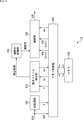
- FIG. 21 is a block diagram illustrating a configuration example of a signal processing device to which the present technology is applied.
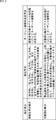
- FIG. 4 is a diagram illustrating an example of a method of detecting a motion and a method of determining a target interpolation rate.
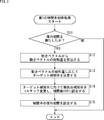
- 9 is a flowchart illustrating a flow of a first interpolation rate control process. It is a figure showing an example of an interpolation rate width for every kind of video contents. It is a figure showing an example of transition of an interpolation rate according to a motion amount. It is a flowchart explaining the flow of an interpolation process.
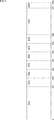
- FIG. 9 is a diagram illustrating an example of displaying an interpolated image frame according to an interpolation ratio.
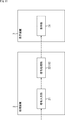
- FIG. 7 is a diagram illustrating an example of a method of detecting a shake and a method of determining a target interpolation rate. It is a flowchart explaining the flow of the 2nd interpolation rate control processing. It is a block diagram showing a configuration example of a display device to which the present technology is applied.
- FIG. 21 is a block diagram illustrating a configuration example of a processing device to which the present technology is applied.
- FIG. 14 is a diagram illustrating a configuration example of a computer.
- FIG. 1 is a block diagram illustrating a configuration example of a signal processing device to which the present technology is applied.
- a signal processing device 10 is incorporated in, for example, a television receiver, and performs signal processing on a video signal that has been subjected to processing such as channel selection and decoding by a tuner and a decoder provided in the preceding stage thereof. Is output to a subsequent circuit (a circuit related to video display).
- the signal processing device 10 includes a pre-processing unit 101, a memory control unit 102, a memory 103, a motion vector detection unit 104, an interpolation rate control unit 105, and an interpolation unit 106.
- the digital component signal YUV is input as a video signal, supplied to the preprocessing unit 101, and sequentially written to the memory 103 via the memory control unit 102.
- the digital component signal YUV is a video signal composed of a luminance signal Y and color difference signals U and V.
- the digital component signal YUV is processed in units of frames, and the original frame of the video signal (original frame) is referred to as an original frame to distinguish it from an interpolated image frame described later.
- the pre-processing unit 101 performs a process of separating the luminance signal Y from the digital component signal YUV.
- the luminance signal Y separated by the preprocessing unit 101 is sequentially written to the memory 103 via the memory control unit 102.
- the luminance signal Y written in the memory 103 is sequentially read out by the memory control unit 102 and supplied to the motion vector detection unit 104.
- the motion vector detection unit 104 performs a motion vector detection process by block matching using the luminance signal Y of the current original image frame and the luminance signals Y of the original image frames before and after it.
- the motion vector mv of each original image frame detected by the motion vector detection unit 104 is written into the memory 103 via the memory control unit 102, read out from the memory 103, and used in the motion vector detection of the next original image frame. It is returned to the motion vector detection unit 104 for reference.
- the memory control unit 102 reads out the digital component signal YUV written in the memory 103 in a predetermined frame unit suitable for the interpolation processing by the interpolation unit 106, and supplies the digital component signal YUV to the interpolation unit 106 together with the motion vector mv.
- the digital component signal YUV written in the memory 103 is read for two systems. Further, the memory control unit 102 reads out a motion vector mv representing the motion between the two original picture frames.
- the two-component digital component signals YUV (prev, succ) and the motion vector mv thus read are supplied to the interpolation unit 106.
- the motion vector detection unit 104 detects the motion of the entire screen or the object based on the detected motion vector mv of each original image frame, and supplies the motion detection result to the interpolation rate control unit 105. However, it is assumed that the motion detection result supplied to the interpolation rate control unit 105 is synchronized with the digital component signal YUV (prev, succ) and the motion vector mv supplied to the interpolation unit 106.
- the interpolation rate control unit 105 includes, for example, a CPU (Central Processing Unit).
- the interpolation rate control unit 105 controls the interpolation rate of the interpolated image frame based on the motion detection result supplied from the motion vector detection unit 104. For example, the interpolation rate control unit 105 determines a target interpolation rate as a target of the interpolation rate based on the motion amount detected from the original image frame, and gradually sets the interpolation rate so as to sequentially approach the determined target interpolation rate. Control.
- a target interpolation rate as a target of the interpolation rate based on the motion amount detected from the original image frame
- the interpolation rate control unit 105 controls the interpolation rate according to the movement in a certain direction between the original frames.
- video scenes such as when the screen is panning in a certain direction, when the screen is zoomed in or out, and when the screen is rotated are detected, and the video scenes are detected.
- the interpolation rate is controlled according to the scene.
- the interpolated image frame is a frame for interpolating between original image frames (original frames) along the time axis.
- the original image frame (prev) and the original image frame (succ) along the time axis are input to the interpolation unit 106 as the digital component signal YUV (prev, succ), the original image frame (prev) and the original image
- the interpolation ratio of the interpolated image frame for interpolating between the frames (succ) is controlled.
- the interpolation ratio is a ratio indicating the degree of interpolation of an interpolated image frame inserted (added) between original image frames along the time axis. For example, if the frame rate is converted from 24 Hz to 120 Hz, four interpolated image frames are required between the original image frames (prev, succ). The position of the object in the interpolated image frame inserted (added) to the image can be changed.
- the interpolation rate is set to 100%, and the interpolation rate is set to 50% or 25%. If the rate is lowered, the movement will not be uniform, and the lower the interpolation rate, the closer the interpolated picture frame will be to the original picture frame, and the original picture frame itself will have an interpolation rate of 0%.
- the digital component signal YUV (prev, succ) and the motion vector mv from the memory control unit 102 and the interpolation rate from the interpolation rate control unit 105 are synchronously input to the interpolation unit 106.
- the interpolation unit 106 generates and interpolates an interpolated image frame for interpolating between the preceding and succeeding original image frames (prev, succ) based on the interpolation ratio, and outputs the interpolated digital component signal YUV to a subsequent circuit. .
- an interpolated image frame is generated as follows. That is, in order to calculate the pixel value of the interpolated image frame based on the parameter of the interpolation position according to the interpolation rate of the video in each interpolated image frame and the motion vector mv between the preceding and succeeding original image frames (prev, succ). After calculating the addresses of the pixels of the original picture frame (prev, succ) before and after the use, interpolation is performed by weighting the pixel values of those addresses in accordance with the interpolation position according to the interpolation ratio, and the interpolation picture frame is obtained. Generated.
- the signal processing device 10 when generating (inserting) an interpolated image frame with respect to the original image frame (prev, succ) along the time axis, a fixed interval between the original image frames (prev, succ) is obtained. (For example, the amount of motion detected from the original image frame), the interpolation rate of the interpolated image frame is determined, and the original image frame (prev, succ) is determined based on the determined interpolation rate. , An interpolation image frame is generated (inserted).
- FIG. 2 is a diagram illustrating an example of a method of detecting a motion based on a motion vector and a method of determining a target interpolation rate according to a result of the motion detection.
- the detection items detected from the original image frame include, for example, two types of movement of the entire screen and movement of an object included in the screen.
- the entire area of the screen corresponds to the area corresponding to the original image frame.
- the following detection method can be used. That is, the motion vectors of the entire screen are respectively integrated in eight directions of the left direction, the upper left direction, the upper direction, the upper right direction, the right direction, the lower right direction, the lower direction, and the lower left direction, and the resulting motion vectors in each direction are obtained. The specific direction in which the largest motion vector sum is obtained from the sum is determined as the motion direction of the entire screen.
- the interpolation rate control unit 105 determines the target interpolation rate according to the detected motion vector total amount of the entire screen.
- the target interpolation rate is determined according to the amount of motion of the video scene in a certain direction (the amount of motion of the entire screen).
- the following detection method can be used for detecting the movement of the object. That is, the largest motion vector sum S among the above eight directions (left direction, upper left direction, upper direction, upper right direction, right direction, lower right direction, lower direction, and lower left direction) is defined as:
- the motion vector sum amount S 'of the target object can be used.
- the value is converted (converted) into a value for the entire screen.
- the ratio of the entire screen to the area corresponding to the moving object can be calculated.
- the interpolation rate control unit 105 determines the target interpolation rate according to the detected motion vector total amount S ′ of the target object.
- a video scene such as a moving object such as a person or a vehicle fixed with a camera is detected, and a motion amount in a certain direction (movement of the object) is detected.
- the target interpolation rate is determined according to the amount.
- the movement of the entire screen and the movement of the target object are described as the detection items, but the target interpolation rate can be determined according to at least one of the movement amounts. Further, the movement of the entire screen and the movement of the object are examples of parameters according to the scene of the video, and other parameters may be used.
- FIG. 3 is a flowchart illustrating a flow of the first interpolation rate control process executed by the interpolation rate control unit 105 of FIG.
- step S11 the interpolation rate control unit 105 determines whether the interpolation rate (current interpolation rate) set in the interpolation unit 106 satisfies the holding period. If it is determined in step S11 that the current interpolation rate satisfies the holding period, the process proceeds to step S12. In this determination processing, for example, the timing of a vertical synchronization signal (V: Vertical @ Sync) such as 10 V is determined.
- V Vertical @ Sync
- step S12 the interpolation rate control unit 105 calculates the total amount of motion vectors based on the motion vectors detected by the motion vector detection unit 104.
- the total motion vector amount of the entire screen or the total motion vector amount of the object is obtained.
- step S13 the interpolation rate control unit 105 determines a target interpolation rate according to the calculated motion vector total amount.
- the target interpolation rate according to the total motion vector amount of the entire screen or the target interpolation rate according to the total motion vector amount of the object is determined.
- step S14 the interpolation rate control unit 105 changes the current interpolation rate by one step toward the determined target interpolation rate, and sets the current interpolation rate in the interpolation unit 106.
- the target interpolation rate is determined to be 100%
- the change unit is set to 10%
- the interpolation rate set in the interpolation unit 106 is set to 60%. If there is, it is advanced by one step, and the interpolation rate is changed to 70%.
- step S15 the interpolation rate control unit 105 sets a holding period of the interpolation rate.
- a timing of a vertical synchronizing signal such as 10 V is set as a holding period of the interpolation rate used in the determination processing of step S11.
- step S15 When the process in step S15 ends, the process proceeds to an end. If it is determined in step S11 that the holding period such as the timing of 10 V is not satisfied, steps S12 to S15 are skipped, and the process proceeds to the end. Here, the process from the start to the end is performed within 1 V, and is restarted from the start at the next V.
- steps S11 to S15 is repeated at a predetermined timing such as 1V, and when a predetermined holding period such as 10V is satisfied (“YES” in S11), the processing is performed in accordance with the motion vector total amount.
- the target interpolation ratio is determined (S13), and the current interpolation ratio is changed step by step so as to gradually approach the target interpolation ratio and set in the interpolation unit 106 (S14).
- the target interpolation rate is determined to be 100% and the current interpolation rate is 60%, the interpolation rate is set to 70%, and then the interpolation rates are set to 80% and 90% at 10 V timing. %, The current interpolation rate is changed stepwise (for example, in units of 10% interpolation rate) so as to sequentially approach the target interpolation rate of 100%, and finally becomes 100%.
- the target interpolation rate is not limited to a fixed value, but may be a variable value. For example, in the above example, if the video scene is switched at the timing when the current interpolation rate is changed to the interpolation rate of 90% toward the target interpolation rate of 100%, and the target interpolation rate is changed to 70%, The current interpolation rate is changed stepwise (for example, in units of 10%) toward the changed target interpolation rate of 70%, such as 90%, 80%, and 70%.
- the flow of the first interpolation rate control process has been described above.
- the interpolation rate of the interpolated image frame is controlled according to the movement in a certain direction between the original image frames. You. More specifically, when controlling the interpolation rate, the target interpolation rate is determined based on the motion amount detected from the original image frame, and the interpolation rate is controlled based on the determined target interpolation rate.
- FIG. 4 shows an example of the interpolation rate width for each type of video content.
- the interpolation rate control unit 105 performs the first interpolation rate control process, and sets the interpolation rate of the interpolated image frame within the range of the interpolation rate width of 40 to 90%. Control to change. That is, the interpolation rate range is a range in which the interpolation rate determined for each type of video content can be changed.
- the interpolation rate width is 50 to 90%
- the interpolation rate width is 80 to 100%
- the range from a low interpolation rate such as 40% to an interpolation rate less than 100% such as 90% can be changed in order to maintain a low frame rate material feeling.
- a low interpolation rate such as 40%
- an interpolation rate less than 100% such as 90%
- shooting is often performed at a frame rate such as 60 Hz, and the number of interpolated frames to be interpolated is small. It is desirable that a changeable range, such as an interpolation rate width of 100%, be set higher.
- FIG. 5 shows an example of transition of the interpolation rate according to the amount of motion.
- the horizontal axis represents a movement amount such as a movement (pan detection amount) of the entire screen in a certain direction.
- control can be performed so as to increase the interpolation rate as the amount of motion indicated on the horizontal axis increases.
- a scene in which a judder is noticeable such as a pan scene
- an interpolation rate for example, an interpolation rate of 60%
- Control is performed to increase the interpolation rate (toward the target interpolation rate).
- FIG. 6 is a flowchart illustrating the flow of the interpolation process performed by the interpolation unit 106 of FIG.
- step S31 the interpolation unit 106 determines whether the interpolation rate set by the interpolation rate control unit 105 has been changed. If it is determined in step S31 that the interpolation rate has been changed, the process proceeds to step S32.
- step S32 the interpolation unit 106 changes the current interpolation rate according to the control from the interpolation rate control unit 105.
- a predetermined holding period such as 10 V
- the current interpolation rate is changed one step at a time toward the target interpolation rate, and set in the interpolation unit 106. Is done.
- step S32 When the process in step S32 ends, the process proceeds to step S33. If it is determined in step S31 that the interpolation ratio has not been changed, step S32 is skipped, and the process proceeds to step S33.
- step S33 the interpolation unit 106 generates an interpolation image frame corresponding to the interpolation rate set by the interpolation rate control unit 105 based on the digital component signal YUV (prev, succ) and the motion vector mv from the memory control unit 102. Generate.
- the number of interpolated image frames corresponding to the frame rate conversion is inserted between the original image frames (prev, succ), but based on the interpolation rate set by the interpolation rate control unit 105, the lower the interpolation rate, the lower the interpolation rate. , An interpolated image frame closer to the original image frame is generated.
- step S33 it is determined whether to end the processing.
- step S34 If it is determined in step S34 that the process is not to be ended, the process returns to step S31, and the processes of steps S31 to S34 are repeated.
- the interpolation rate set in the interpolation unit 106 is changed stepwise so as to sequentially approach the target interpolation rate, and an interpolated image frame corresponding to the changed interpolation rate is generated. Is done.
- step S34 If it is determined in step S34 that the processing is to be ended, the interpolation processing is ended.
- the interpolation processing when generating an interpolation image frame for an original image frame along the time axis, the interpolation processing is performed in accordance with the interpolation rate set by the above-described first interpolation rate control processing (the processing of step S14 in FIG. 3). An interpolated image frame is generated.
- FIG. 7 shows an example of display of an interpolated image frame according to the interpolation ratio.
- 7A shows the case where the interpolation rate is 100%
- FIG. 7B shows the case where the interpolation rate is 50%.
- the time direction is a direction from the left side to the right side in the figure.
- Interpolated image frames # 1 to # 4 are inserted between the original image frames # 1 and # 2, respectively.
- FIG. 7A when the interpolation rate is 100%, it is assumed that the change position between the original image frame # 1 and the original image frame # 2 is moved uniformly, and the interpolation image frames # 1 A and # 1 2A , an interpolated image frame # 3A , and an interpolated image frame # 4A are respectively generated. More specifically, in FIG. 7A, when the object moves from right to left on the screen when attention is paid to the original frames # 1 and # 2, the original frames # 1 and # 2 are Focusing on the interpolated image frames # 1 A to # 4 A interpolated during # 2, the object in the screen moves evenly from right to left in the screen for each interpolated image frame. I have.
- FIG. 7B when the interpolation rate is 50%, the movement is not uniform as in the case of the above-described interpolation rate of 100%. That is, when the interpolation rate is 50%, of the four interpolated picture frames # 1 B to # 4 B inserted between the original picture frames # 1 and # 2, two interpolation pictures from the original picture frame # 1 are used.
- the image frames # 1 B and # 2 B are images based on the original image frame # 1 by 50% compared to the case where the interpolation rate is 100%, while two interpolated image frames from the original image frame # 2 # 3 B, # 4 B is an image that by only 50% partial original frame # 2 side as compared with the case of the interpolation rate of 100%.
- the two interpolated picture frames # 1 and # 2 from the original picture frame # 1 are further reduced by 50% compared to the case where the interpolation rate is 50%. Only the original frame # 1 side is used as the image, while the two interpolated image frames # 3 and # 4 from the original frame # 2 are 50% more original frames than the case where the interpolation ratio is 50%. The image is based on the # 2 side.
- the two interpolated image frames # 1 and # 2 from the original image frame # 1 become the same image as the original image frame # 1, while the two interpolated image frames # 1 and # 2 from the original image frame # 2.
- the interpolation image frames # 3 and # 4 are the same images as the original image frame # 2.
- the interpolation rate is 0%, three original picture frames # 1 and three original picture frames # 2 are sequentially displayed (the original picture frames are # 1, # 1, # 1, # 2). , # 2, # 2).
- the interpolation image frames (for example, four interpolation image frames # 1 and # 2) are compared with the original image frames (for example, original image frames # 1 and # 2) along the time axis. , # 3, # 4), the target interpolation rate is determined based on the motion amount detected from the original image frame (for example, the motion of the entire screen or the motion of the object). Based on this, the interpolation rate of the interpolation image frame is controlled.
- the interpolation rate for each video content is fixed (for example, the interpolation rate for movies is fixed at X%, and the interpolation rate for animation is set at Y%) Control, etc.), it is not possible to perform control corresponding to a scene where judder is better or a scene where judder is better.
- the control for changing the interpolation rate when the control for changing the interpolation rate is performed according to the video scene, it is possible to perform the control for changing the movable range of the interpolation rate depending on the type of the video content. It is possible to set an appropriate interpolation rate, and it is possible to provide a video that is more easily viewable by changing the interpolation rate depending on the scene.
- Patent Document 1 the processing amount in the imaging blur suppression process is changed according to the reliability at the time of detecting the motion vector, or the gain by which the motion vector is multiplied is changed according to the reliability. I have.
- a control for changing the interpolation rate by detecting whether the screen is oriented in a certain direction or the main target is oriented in a certain direction Is what you do.
- the second embodiment is different from the first embodiment in that the interpolation rate control unit 105 determines the target interpolation rate based on the amount of shaking detected from the original image frame in the signal processing device 10 of FIG.
- the configuration is different from that of the embodiment, the other configuration is the same, and the description of the overlapping part will be appropriately omitted.
- FIG. 8 is a diagram illustrating an example of a method of detecting a shake based on a motion vector and a method of determining a target interpolation rate according to a result of the detection of the shake.
- the detection items detected from the original image frame include, for example, two types of shaking of the entire screen and shaking of the object.
- the following detection method can be used to detect the shaking of the entire screen, for example. That is, in four combinations of diagonal left and right directions, upper left and lower right directions, upper and lower directions, and upper right and lower left directions, the magnitude of the motion vector amount of the entire screen is several Vs. When there is a combination that is exchanged every (Vertical @ Sync), it is determined that the entire screen is shaking.
- the swing amount of the entire screen can be obtained from the motion vector amount of the combination determined to be swinging. That is, based on the motion vector amount obtained for each predetermined combination in the diagonal direction on the entire screen, the fluctuation amount that is the sum of the fluctuations in the specific diagonal combination is calculated.
- the interpolation rate control unit 105 determines the target interpolation rate according to the detected amount of fluctuation of the entire screen.
- the following detection method can be used for the detection of the shaking of the target object. That is, the largest swing amount T among the swing amounts of the above four combinations (the combination of the left direction and the right direction, the upper left direction and the lower right direction, the upper direction and the lower direction, and the upper right direction and the lower left direction) is The swing amount T 'of the object can be used, but here, the value is converted (converted) into a value for the entire screen.
- the ratio of the area corresponding to the object (moving object) to the entire screen is determined. Since the ratio can be calculated, the swing amount T can be converted into the swing amount T ′ of the target object using the ratio. More specifically, the swing amount T ′ of the object satisfies the relationship of the following equation (2).
- T ' T ⁇ 100 / (100-A) ⁇ ⁇ ⁇ (2)
- the interpolation rate control unit 105 determines the target interpolation rate according to the detected swing amount T ′ of the target object.
- the swing of the entire screen and the swing of the object are described as the detection items, but the target interpolation rate can be determined according to at least one of the swing amounts.
- the shake of the entire screen and the shake of the object are examples of parameters according to the scene of the video, and other parameters may be used.
- FIG. 9 is a flowchart illustrating the flow of the second interpolation rate control process executed by the interpolation rate control unit 105 of FIG.
- steps S51 to S55 a process of controlling the interpolation rate is performed in the same manner as in steps S11 to S15 in FIG. 3, but in step S53, when determining the target interpolation rate, the motion vector obtained from the motion vector is determined. The difference is that a swing amount obtained from a motion vector is used instead of the total amount.
- the processing of steps S51 to S55 is repeated at a predetermined timing such as 1 V, and when a predetermined holding period such as 10 V is satisfied (“YES” in S51),
- the target interpolation rate according to the swing amount is determined (S53), and the current interpolation rate is changed step by step by one step so as to sequentially approach the target interpolation rate and set in the interpolation unit 106 (S54).
- the second interpolation rate control process when an interpolated image frame is generated for an original image frame along the time axis, the interpolation rate of the interpolated image frame is controlled according to the movement between the original image frames. More specifically, when controlling the interpolation rate, the target interpolation rate is determined based on the amount of fluctuation detected from the original image frame, and the interpolation rate is controlled based on the determined target interpolation rate.
- the signal processing device 10 has been described as an independent device, but may be configured to be included in a device such as a display device.
- FIG. 10 is a block diagram illustrating a configuration example of a display device to which the present technology is applied.
- the display device 1 is a device having a display unit, such as a television receiver, a display device, a personal computer, a tablet terminal, a smartphone, a mobile phone, a head-mounted display, and a game machine.
- a display unit such as a television receiver, a display device, a personal computer, a tablet terminal, a smartphone, a mobile phone, a head-mounted display, and a game machine.
- the display device 1 includes a signal input unit 11, a signal processing unit 12, and a display unit 13.
- the signal input unit 11 is configured as a tuner, for example, and supplies a video signal obtained by demodulating a broadcast signal received via an antenna to the signal processing unit 12.
- the broadcast signal here includes, for example, a video signal of broadcast content transmitted according to a predetermined broadcast system such as terrestrial broadcast or satellite broadcast.
- the signal input unit 11 is not limited to a tuner.
- the signal input unit 11 is configured as a communication module, and a video signal of communication content distributed via a communication network such as the Internet is input to the signal processing unit 12. You may make it.
- the signal input unit 11 is configured as an interface compliant with a predetermined standard such as, for example, HDMI (High Definition Multimedia Interface) (registered trademark) or USB (Universal Serial Bus).
- a predetermined standard such as, for example, HDMI (High Definition Multimedia Interface) (registered trademark) or USB (Universal Serial Bus).
- HDMI High Definition Multimedia Interface
- USB Universal Serial Bus
- the video signal of the recorded content recorded or the recorded content recorded on a recording medium such as an optical disk or a semiconductor memory may be input to the signal processing unit 12.
- Video signals of various contents can be converted into digital component signals YUV and input to the signal processing unit 12.
- the signal processing unit 12 has a configuration corresponding to the signal processing device 10 in FIG.
- the signal processing unit 12 performs an interpolation rate control process (FIG. 3 or FIG. 9) and an interpolation process (FIG. 6) on the video signal (digital component signal YUV) supplied from the signal input unit 11.
- a video signal in which an interpolation image frame is inserted into an original image frame by interpolation rate control processing or interpolation processing is supplied to the display unit 13.
- the display unit 13 includes, for example, a liquid crystal display unit such as an LCD (Liquid Crystal Display) and a self-luminous display unit such as an OLED (Organic Light Emitting Diode).
- the display unit 13 is driven by, for example, converting a video signal supplied from the signal processing unit 12 into an RGB signal as necessary, and displays a video (image) corresponding to the video signal.
- FIG. 11 is a block diagram illustrating a configuration example of a display system to which the present technology is applied.
- the display system includes a processing device 2 and a display device 3.
- the processing device 2 is a device such as a set-top box, a recorder, a player (player), and a storage device.
- the display device 3 is, for example, a device such as a display device, a television receiver, a tablet terminal, or a personal computer.
- the processing device 2 and the display device 3 are connected by a cable or the like via an interface conforming to a predetermined standard.
- the processing device 2 includes a signal input unit 21 and a signal processing unit 22.
- the signal input unit 21 is configured as, for example, an interface conforming to a predetermined standard such as a tuner, a communication module, HDMI (registered trademark) and USB, converts a video signal into a digital component signal YUV, and sends the converted signal to the signal processing unit 22. input.
- a predetermined standard such as a tuner, a communication module, HDMI (registered trademark) and USB
- the signal processing unit 22 has a configuration corresponding to the signal processing device 10 in FIG.
- the signal processing unit 22 performs an interpolation rate control process (FIG. 3 or FIG. 9) and an interpolation process (FIG. 6) on the video signal (digital component signal YUV) supplied from the signal input unit 21.
- the video signal in which the interpolation image frame is inserted into the original image frame by the interpolation rate control processing or the interpolation processing is output to the display device 3 via a predetermined interface such as a cable.
- the signal processing unit 22 has a configuration including a processing unit that performs signal conversion suitable for a predetermined interface on the digital component signal YUV.
- the display device 3 is configured to include the display unit 31.
- the display unit 31 includes, for example, a liquid crystal display unit such as an LCD and a self-luminous display unit such as an OLED.
- the display unit 31 is driven based on a video signal input from the processing device 2 and displays a video (image) corresponding to the video signal.
- the processing device 2 and the display device 3 are connected via a predetermined interface such as a cable.
- a predetermined interface such as a cable.
- the present invention is not limited thereto. Signals may be exchanged.
- the target interpolation rate is determined based on the motion amount of the entire screen or the object detected from the motion vector of the original image frame in the first embodiment
- the second embodiment will be described.
- the target interpolation rate is determined based on the entire screen or the amount of shake of the object detected from the motion vector of the original image frame, but based on the amount of movement and the amount of movement of the entire screen or the object.
- the target interpolation rate may be determined.
- the interpolation rate control unit 105 determines the target interpolation rate based on at least one of the motion amount and the fluctuation amount detected from the original image frame, and controls the interpolation rate stepwise so as to sequentially approach the determined target interpolation rate. can do.
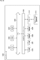
- FIG. 12 is a block diagram illustrating a configuration example of hardware of a computer that executes the series of processes described above by a program.
- a CPU Central Processing Unit
- ROM Read Only Memory
- RAM Random Access Memory
- An input / output interface 1005 is further connected to the bus 1004.
- the input / output interface 1005 is connected to an input unit 1006, an output unit 1007, a recording unit 1008, a communication unit 1009, and a drive 1010.
- the input unit 1006 includes a microphone, a keyboard, a mouse, and the like.
- the output unit 1007 includes a speaker, a display, and the like.
- the recording unit 1008 includes a hard disk, a nonvolatile memory, and the like.
- the communication unit 1009 includes a network interface and the like.
- the drive 1010 drives a removable recording medium 1011 such as a magnetic disk, an optical disk, a magneto-optical disk, or a semiconductor memory.
- the CPU 1001 loads the program recorded in the ROM 1002 or the recording unit 1008 into the RAM 1003 via the input / output interface 1005 and the bus 1004 and executes the program, thereby executing the above-described operation. A series of processing is performed.
- the program executed by the computer 1000 can be provided by being recorded on, for example, a removable recording medium 1011 as a package medium or the like.
- the program can be provided via a wired or wireless transmission medium such as a local area network, the Internet, or digital satellite broadcasting.
- the program can be installed in the recording unit 1008 via the input / output interface 1005 by attaching the removable recording medium 1011 to the drive 1010.
- the program can be received by the communication unit 1009 via a wired or wireless transmission medium and installed in the recording unit 1008.
- the program can be installed in the ROM 1002 or the recording unit 1008 in advance.
- the processing performed by the computer according to the program does not necessarily need to be performed in chronological order in the order described in the flowchart. That is, the processing performed by the computer in accordance with the program includes processing executed in parallel or individually (for example, parallel processing or processing by an object). Further, the program may be processed by one computer (processor), or may be processed in a distributed manner by a plurality of computers.
- Each step of the interpolation rate control process shown in FIG. 3 or FIG. 9 can be executed by a single device, or can be shared and executed by a plurality of devices. Further, when a plurality of processes are included in one step, the plurality of processes included in the one step can be executed by one device, or can be shared and executed by a plurality of devices.
- the interpolation rate of the interpolated image frame is controlled in accordance with a movement in a certain direction between the original images.
- a display device including a signal processing unit.
- the signal processing unit Based on the amount of motion detected from the original image frame, determine a target interpolation rate as a target of the interpolation rate, The display device according to (1), wherein the control unit controls the interpolation ratio based on the determined target interpolation ratio.
- the signal processing unit changes the interpolation rate stepwise so as to sequentially approach the determined target interpolation rate.
- the signal processing unit Based on the amount of motion detected from the original image frame, change the target interpolation rate, The display device according to (3), wherein the interpolation ratio is changed stepwise so as to sequentially approach the changed target interpolation ratio.
- the signal processing unit Based on the motion vector obtained for each predetermined direction in the entire screen corresponding to the original image frame, calculate the total amount of motion vectors in a specific direction, The display device according to (2), wherein the target interpolation ratio is determined according to the calculated motion vector total amount.
- the signal processing unit Based on the motion vector obtained for each predetermined direction in the entire screen corresponding to the original image frame, calculate the total motion vector amount of the target in a specific direction in a predetermined area corresponding to the entire screen, The display device according to (2) or (7), wherein the target interpolation ratio is determined according to the calculated motion vector total amount of the target object.
- the signal processing unit Based on the fluctuation amount detected from the original image frame, determine a target interpolation rate as a target of the interpolation rate, The display device according to any one of (1) to (8), wherein the interpolation ratio is controlled based on the determined target interpolation ratio.
- the signal processing unit Based on the motion vector amount obtained for each predetermined diagonal combination in the entire screen corresponding to the original image frame, calculate a swing amount that is the sum of the fluctuations in the specific diagonal combination, The display device according to (9), wherein the target interpolation ratio is determined according to the calculated swing amount.
- the signal processing unit Based on the motion vector amount obtained for each predetermined diagonal combination in the entire screen corresponding to the original image frame, the fluctuation of the target object in a specific diagonal combination in a predetermined area corresponding to the entire screen Calculate the swing amount that is the sum of The display device according to (9) or (10), wherein the target interpolation ratio is determined according to the calculated swing amount of the target object.
- the interpolation ratio is a ratio indicating a degree of interpolation of the interpolated image frame.
- the signal processing unit Further comprising a motion vector detection unit for detecting a motion vector from the original image frame, The display device according to (14), wherein the interpolation rate control unit controls the interpolation rate based on the detected motion vector.
- the interpolation rate of the interpolated picture frame is controlled according to a movement in a certain direction between the original picture frames.
- a signal processing device including an interpolation rate control unit.
- the signal processing device When generating an interpolated picture frame for interpolating between the original picture frames with respect to the original picture frame along the time axis, the interpolation rate of the interpolated picture frame is controlled according to a movement in a certain direction between the original picture frames. Signal processing method.
Landscapes
- Engineering & Computer Science (AREA)
- Multimedia (AREA)
- Signal Processing (AREA)
- Physics & Mathematics (AREA)
- Computer Hardware Design (AREA)
- General Physics & Mathematics (AREA)
- Theoretical Computer Science (AREA)
- Television Systems (AREA)
Priority Applications (4)
| Application Number | Priority Date | Filing Date | Title |
|---|---|---|---|
| CN201980052826.3A CN112544075B (zh) | 2018-08-22 | 2019-08-08 | 显示装置、信号处理装置和信号处理方法 |
| EP19850884.8A EP3843380A4 (de) | 2018-08-22 | 2019-08-08 | Anzeigevorrichtung, signalverarbeitungsvorrichtung und signalverarbeitungsverfahren |
| JP2020538303A JP7630993B2 (ja) | 2018-08-22 | 2019-08-08 | 表示装置、信号処理装置、及び信号処理方法 |
| US17/267,869 US11930207B2 (en) | 2018-08-22 | 2019-08-08 | Display device, signal processing device, and signal processing method |
Applications Claiming Priority (2)
| Application Number | Priority Date | Filing Date | Title |
|---|---|---|---|
| JP2018-155482 | 2018-08-22 | ||
| JP2018155482 | 2018-08-22 |
Publications (1)
| Publication Number | Publication Date |
|---|---|
| WO2020039956A1 true WO2020039956A1 (ja) | 2020-02-27 |
Family
ID=69593140
Family Applications (1)
| Application Number | Title | Priority Date | Filing Date |
|---|---|---|---|
| PCT/JP2019/031337 Ceased WO2020039956A1 (ja) | 2018-08-22 | 2019-08-08 | 表示装置、信号処理装置、及び信号処理方法 |
Country Status (5)
| Country | Link |
|---|---|
| US (1) | US11930207B2 (de) |
| EP (1) | EP3843380A4 (de) |
| JP (1) | JP7630993B2 (de) |
| CN (1) | CN112544075B (de) |
| WO (1) | WO2020039956A1 (de) |
Families Citing this family (2)
| Publication number | Priority date | Publication date | Assignee | Title |
|---|---|---|---|---|
| US12298181B2 (en) * | 2023-09-06 | 2025-05-13 | Apple Inc. | Systems and methods for crosstalk mitigation between ambient light sensor and electronic display |
| KR20250127655A (ko) * | 2024-02-19 | 2025-08-26 | 엘지전자 주식회사 | 디스플레이 장치 및 그 동작 방법 |
Citations (7)
| Publication number | Priority date | Publication date | Assignee | Title |
|---|---|---|---|---|
| WO2008102827A1 (ja) | 2007-02-20 | 2008-08-28 | Sony Corporation | 画像表示装置、映像信号処理装置および映像信号処理方法 |
| WO2010067519A1 (ja) * | 2008-12-10 | 2010-06-17 | パナソニック株式会社 | 映像処理装置及び映像処理方法 |
| WO2011067869A1 (ja) * | 2009-12-01 | 2011-06-09 | パナソニック株式会社 | 画像処理装置及び画像処理方法 |
| WO2011067870A1 (ja) * | 2009-12-01 | 2011-06-09 | パナソニック株式会社 | 画像処理装置および画像処理方法 |
| WO2012117461A1 (ja) * | 2011-03-03 | 2012-09-07 | パナソニック株式会社 | 立体映像処理装置および方法ならびに立体映像表示装置 |
| WO2012117464A1 (ja) * | 2011-03-03 | 2012-09-07 | パナソニック株式会社 | 立体映像処理装置および方法ならびに立体映像表示装置 |
| JP2013048376A (ja) * | 2011-08-29 | 2013-03-07 | Jvc Kenwood Corp | 動き補償フレーム生成装置及び方法 |
Family Cites Families (8)
| Publication number | Priority date | Publication date | Assignee | Title |
|---|---|---|---|---|
| JP2008017023A (ja) * | 2006-07-04 | 2008-01-24 | Canon Inc | 映像信号処理装置 |
| JP4181592B2 (ja) * | 2006-09-20 | 2008-11-19 | シャープ株式会社 | 画像表示装置及び方法、画像処理装置及び方法 |
| US8259226B2 (en) * | 2006-11-24 | 2012-09-04 | Sharp Kabushiki Kaisha | Image display device |
| EP2234402B1 (de) * | 2009-03-25 | 2012-07-04 | Bang & Olufsen A/S | Methode und System zur Anpassung der Korrektur von Filmruckeln |
| JP5558766B2 (ja) * | 2009-09-24 | 2014-07-23 | キヤノン株式会社 | 画像処理装置及びその制御方法 |
| JP2011211370A (ja) * | 2010-03-29 | 2011-10-20 | Renesas Electronics Corp | 画像処理装置および画像処理方法 |
| EP3111635B1 (de) * | 2014-02-27 | 2018-06-27 | Dolby Laboratories Licensing Corporation | Systeme und verfahren zur steuerung der ruckelsichtbarkeit |
| CN103929648B (zh) * | 2014-03-27 | 2017-04-19 | 华为技术有限公司 | 一种帧率上采样中的运动估计方法和装置 |
-
2019
- 2019-08-08 JP JP2020538303A patent/JP7630993B2/ja active Active
- 2019-08-08 EP EP19850884.8A patent/EP3843380A4/de active Pending
- 2019-08-08 WO PCT/JP2019/031337 patent/WO2020039956A1/ja not_active Ceased
- 2019-08-08 CN CN201980052826.3A patent/CN112544075B/zh active Active
- 2019-08-08 US US17/267,869 patent/US11930207B2/en active Active
Patent Citations (8)
| Publication number | Priority date | Publication date | Assignee | Title |
|---|---|---|---|---|
| WO2008102827A1 (ja) | 2007-02-20 | 2008-08-28 | Sony Corporation | 画像表示装置、映像信号処理装置および映像信号処理方法 |
| WO2008102826A1 (ja) * | 2007-02-20 | 2008-08-28 | Sony Corporation | 画像表示装置、映像信号処理装置および映像信号処理方法 |
| WO2010067519A1 (ja) * | 2008-12-10 | 2010-06-17 | パナソニック株式会社 | 映像処理装置及び映像処理方法 |
| WO2011067869A1 (ja) * | 2009-12-01 | 2011-06-09 | パナソニック株式会社 | 画像処理装置及び画像処理方法 |
| WO2011067870A1 (ja) * | 2009-12-01 | 2011-06-09 | パナソニック株式会社 | 画像処理装置および画像処理方法 |
| WO2012117461A1 (ja) * | 2011-03-03 | 2012-09-07 | パナソニック株式会社 | 立体映像処理装置および方法ならびに立体映像表示装置 |
| WO2012117464A1 (ja) * | 2011-03-03 | 2012-09-07 | パナソニック株式会社 | 立体映像処理装置および方法ならびに立体映像表示装置 |
| JP2013048376A (ja) * | 2011-08-29 | 2013-03-07 | Jvc Kenwood Corp | 動き補償フレーム生成装置及び方法 |
Non-Patent Citations (1)
| Title |
|---|
| See also references of EP3843380A4 |
Also Published As
| Publication number | Publication date |
|---|---|
| JP7630993B2 (ja) | 2025-02-18 |
| CN112544075A (zh) | 2021-03-23 |
| US20210176488A1 (en) | 2021-06-10 |
| EP3843380A4 (de) | 2021-10-20 |
| JPWO2020039956A1 (ja) | 2021-08-10 |
| US11930207B2 (en) | 2024-03-12 |
| EP3843380A1 (de) | 2021-06-30 |
| CN112544075B (zh) | 2024-01-05 |
Similar Documents
| Publication | Publication Date | Title |
|---|---|---|
| US8269886B2 (en) | Methods and systems for improving low-resolution video | |
| JP5107349B2 (ja) | 動きベクトルに基づく画像のスケーリング | |
| US6061094A (en) | Method and apparatus for scaling and reducing flicker with dynamic coefficient weighting | |
| CN104813361B (zh) | 感知内容的视频尺寸调整 | |
| KR102567633B1 (ko) | 오버레이 지시를 사용하는 적응적 하이 다이나믹 레인지 톤 매핑 | |
| US8593575B2 (en) | Video display apparatus for shortened-delay processing of a video signal and video processing method | |
| US8547479B2 (en) | Display apparatus and control method thereof | |
| JP2005286677A (ja) | 撮像装置 | |
| JP2012169727A (ja) | 映像信号処理装置および映像信号処理方法 | |
| JP7630993B2 (ja) | 表示装置、信号処理装置、及び信号処理方法 | |
| JP7565606B2 (ja) | 画像処理装置および画像処理方法 | |
| WO2017150238A1 (ja) | 表示制御装置、表示制御方法、及び、プログラム | |
| JP5015089B2 (ja) | フレームレート変換装置、フレームレート変換方法、テレビジョン受像機、フレームレート変換プログラムおよび該プログラムを記録した記録媒体 | |
| JP5259867B2 (ja) | 映像表示装置及び映像処理方法 | |
| US8670070B2 (en) | Method and system for achieving better picture quality in various zoom modes | |
| TWI867932B (zh) | 調整視訊訊號的方法 | |
| JP2012227799A (ja) | 画像表示装置 | |
| WO2015155893A1 (ja) | 映像出力装置、映像受信装置、および映像出力方法 | |
| JP2013120369A (ja) | 表示装置および映像処理方法 | |
| JP2014143596A (ja) | 電子機器、電子機器の制御方法、電子機器の制御プログラム | |
| KR20090074624A (ko) | 카메라 움직임 정보를 이용한 중간 프레임 계산 방법 |
Legal Events
| Date | Code | Title | Description |
|---|---|---|---|
| 121 | Ep: the epo has been informed by wipo that ep was designated in this application |
Ref document number: 19850884 Country of ref document: EP Kind code of ref document: A1 |
|
| ENP | Entry into the national phase |
Ref document number: 2020538303 Country of ref document: JP Kind code of ref document: A |
|
| NENP | Non-entry into the national phase |
Ref country code: DE |
|
| ENP | Entry into the national phase |
Ref document number: 2019850884 Country of ref document: EP Effective date: 20210322 |