WO2020040102A1 - ロボットハンド、ロボット及びロボットシステム - Google Patents
ロボットハンド、ロボット及びロボットシステム Download PDFInfo
- Publication number
- WO2020040102A1 WO2020040102A1 PCT/JP2019/032330 JP2019032330W WO2020040102A1 WO 2020040102 A1 WO2020040102 A1 WO 2020040102A1 JP 2019032330 W JP2019032330 W JP 2019032330W WO 2020040102 A1 WO2020040102 A1 WO 2020040102A1
- Authority
- WO
- WIPO (PCT)
- Prior art keywords
- robot
- conveyor
- unit
- transport direction
- rotating shaft
- Prior art date
- Legal status (The legal status is an assumption and is not a legal conclusion. Google has not performed a legal analysis and makes no representation as to the accuracy of the status listed.)
- Ceased
Links
Images


Classifications
-
- B—PERFORMING OPERATIONS; TRANSPORTING
- B65—CONVEYING; PACKING; STORING; HANDLING THIN OR FILAMENTARY MATERIAL
- B65G—TRANSPORT OR STORAGE DEVICES, e.g. CONVEYORS FOR LOADING OR TIPPING, SHOP CONVEYOR SYSTEMS OR PNEUMATIC TUBE CONVEYORS
- B65G47/00—Article or material-handling devices associated with conveyors; Methods employing such devices
- B65G47/74—Feeding, transfer, or discharging devices of particular kinds or types
- B65G47/90—Devices for picking-up and depositing articles or materials
-
- B—PERFORMING OPERATIONS; TRANSPORTING
- B65—CONVEYING; PACKING; STORING; HANDLING THIN OR FILAMENTARY MATERIAL
- B65G—TRANSPORT OR STORAGE DEVICES, e.g. CONVEYORS FOR LOADING OR TIPPING, SHOP CONVEYOR SYSTEMS OR PNEUMATIC TUBE CONVEYORS
- B65G61/00—Use of pick-up or transfer devices or of manipulators for stacking or de-stacking articles not otherwise provided for
-
- B—PERFORMING OPERATIONS; TRANSPORTING
- B25—HAND TOOLS; PORTABLE POWER-DRIVEN TOOLS; MANIPULATORS
- B25J—MANIPULATORS; CHAMBERS PROVIDED WITH MANIPULATION DEVICES
- B25J15/00—Gripping heads and other end effectors
- B25J15/0014—Gripping heads and other end effectors having fork, comb or plate shaped means for engaging the lower surface on a object to be transported
-
- B—PERFORMING OPERATIONS; TRANSPORTING
- B25—HAND TOOLS; PORTABLE POWER-DRIVEN TOOLS; MANIPULATORS
- B25J—MANIPULATORS; CHAMBERS PROVIDED WITH MANIPULATION DEVICES
- B25J15/00—Gripping heads and other end effectors
- B25J15/06—Gripping heads and other end effectors with vacuum or magnetic holding means
- B25J15/0616—Gripping heads and other end effectors with vacuum or magnetic holding means with vacuum
-
- B—PERFORMING OPERATIONS; TRANSPORTING
- B25—HAND TOOLS; PORTABLE POWER-DRIVEN TOOLS; MANIPULATORS
- B25J—MANIPULATORS; CHAMBERS PROVIDED WITH MANIPULATION DEVICES
- B25J5/00—Manipulators mounted on wheels or on carriages
- B25J5/007—Manipulators mounted on wheels or on carriages mounted on wheels
-
- B—PERFORMING OPERATIONS; TRANSPORTING
- B25—HAND TOOLS; PORTABLE POWER-DRIVEN TOOLS; MANIPULATORS
- B25J—MANIPULATORS; CHAMBERS PROVIDED WITH MANIPULATION DEVICES
- B25J9/00—Program-controlled manipulators
- B25J9/003—Program-controlled manipulators having parallel kinematics
- B25J9/0033—Program-controlled manipulators having parallel kinematics with kinematics chains having a prismatic joint at the base
-
- B—PERFORMING OPERATIONS; TRANSPORTING
- B25—HAND TOOLS; PORTABLE POWER-DRIVEN TOOLS; MANIPULATORS
- B25J—MANIPULATORS; CHAMBERS PROVIDED WITH MANIPULATION DEVICES
- B25J9/00—Program-controlled manipulators
- B25J9/0093—Program-controlled manipulators co-operating with conveyor means
-
- B—PERFORMING OPERATIONS; TRANSPORTING
- B65—CONVEYING; PACKING; STORING; HANDLING THIN OR FILAMENTARY MATERIAL
- B65G—TRANSPORT OR STORAGE DEVICES, e.g. CONVEYORS FOR LOADING OR TIPPING, SHOP CONVEYOR SYSTEMS OR PNEUMATIC TUBE CONVEYORS
- B65G41/00—Supporting frames or bases for conveyors as a whole, e.g. transportable conveyor frames
- B65G41/001—Supporting frames or bases for conveyors as a whole, e.g. transportable conveyor frames with the conveyor adjustably mounted on the supporting frame or base
- B65G41/005—Supporting frames or bases for conveyors as a whole, e.g. transportable conveyor frames with the conveyor adjustably mounted on the supporting frame or base mounted for both pivotal and linear movement
-
- B—PERFORMING OPERATIONS; TRANSPORTING
- B65—CONVEYING; PACKING; STORING; HANDLING THIN OR FILAMENTARY MATERIAL
- B65G—TRANSPORT OR STORAGE DEVICES, e.g. CONVEYORS FOR LOADING OR TIPPING, SHOP CONVEYOR SYSTEMS OR PNEUMATIC TUBE CONVEYORS
- B65G47/00—Article or material-handling devices associated with conveyors; Methods employing such devices
- B65G47/74—Feeding, transfer, or discharging devices of particular kinds or types
- B65G47/90—Devices for picking-up and depositing articles or materials
- B65G47/91—Devices for picking-up and depositing articles or materials incorporating pneumatic, e.g. suction, grippers
-
- B—PERFORMING OPERATIONS; TRANSPORTING
- B65—CONVEYING; PACKING; STORING; HANDLING THIN OR FILAMENTARY MATERIAL
- B65G—TRANSPORT OR STORAGE DEVICES, e.g. CONVEYORS FOR LOADING OR TIPPING, SHOP CONVEYOR SYSTEMS OR PNEUMATIC TUBE CONVEYORS
- B65G47/00—Article or material-handling devices associated with conveyors; Methods employing such devices
- B65G47/74—Feeding, transfer, or discharging devices of particular kinds or types
- B65G47/90—Devices for picking-up and depositing articles or materials
- B65G47/91—Devices for picking-up and depositing articles or materials incorporating pneumatic, e.g. suction, grippers
- B65G47/914—Devices for picking-up and depositing articles or materials incorporating pneumatic, e.g. suction, grippers provided with drive systems incorporating rotary and rectilinear movements
-
- B—PERFORMING OPERATIONS; TRANSPORTING
- B25—HAND TOOLS; PORTABLE POWER-DRIVEN TOOLS; MANIPULATORS
- B25J—MANIPULATORS; CHAMBERS PROVIDED WITH MANIPULATION DEVICES
- B25J17/00—Joints
- B25J17/02—Wrist joints
- B25J17/0241—One-dimensional joints
- B25J17/025—One-dimensional joints mounted in series
-
- B—PERFORMING OPERATIONS; TRANSPORTING
- B65—CONVEYING; PACKING; STORING; HANDLING THIN OR FILAMENTARY MATERIAL
- B65G—TRANSPORT OR STORAGE DEVICES, e.g. CONVEYORS FOR LOADING OR TIPPING, SHOP CONVEYOR SYSTEMS OR PNEUMATIC TUBE CONVEYORS
- B65G2201/00—Indexing codes relating to handling devices, e.g. conveyors, characterised by the type of product or load being conveyed or handled
- B65G2201/02—Articles
Definitions
- the present invention relates to a robot hand, a robot, and a robot system.
- the cargo handling device of Patent Document 1 includes a movable conveyor and a take-out arm.
- the movable conveyor advances so as to approach the load, and the load is gripped by the grip provided at the tip of the take-out arm.
- the removal arm places the load on the moving conveyor and then moves to a load avoidance position. Further, the movable conveyor descends to the position of the transfer table, and rotates the belt constituting the transfer surface to load the load into the transfer table.
- the cargo handling device of Patent Document 1 needs to be fixed to the ground at a position adjacent to the transport table, so that there is a problem that the installation place is limited.
- an object of the present invention is to provide a robot hand, a robot, and a robot system that can transfer a workpiece by a movable conveyor without limiting the installation location.
- a robot hand includes a base attached to a tip of a robot arm, a conveyor fixed to the base, and a workpiece held and placed on a transfer surface of the conveyor. And a holding mechanism.
- the conveyor since the conveyor is fixed to the end of the robot arm, the conveyor can be moved within a range in which the end of the robot arm can move. As a result, it is possible to provide a robot hand capable of transporting a workpiece by a movable conveyor without limiting the installation location.
- the holding mechanism is disposed so as to extend in the transport direction of the conveyor along the conveyor, and is attached to the rotary shaft so as to be reciprocally movable or extendable and contractible in the transport direction, and the transport mechanism is provided with the transport mechanism. Swingable about a rotational axis on a plane where a width direction perpendicular to the transport direction intersects a height direction perpendicular to the transport direction and the width direction. And a holding unit that is provided upstream of the swinging unit in the transport direction and holds the work.
- the holding portion provided on the swinging portion allows the swinging portion to be pulled into and placed on the conveying surface of the conveyor while holding the work. it can. Further, since the swinging portion is swingable about the rotation axis on a plane where the width direction and the height direction of the conveyor intersect, after the work is placed on the conveyor surface of the conveyor, the work is placed on the conveyor of the conveyor. The swing unit can be swung to a position where the transfer of the swing unit is not hindered. As described above, it is possible to hold and place a work on the conveyor surface of the conveyor by a holding mechanism having a simple configuration.
- the oscillating portion is formed in a plate shape, is attached to the rotating shaft so that a thickness direction thereof coincides with the transport direction, and the holding portion is located upstream of the oscillating portion in the transport direction. May be attached to the existing main surface.
- the holding mechanism can have a simpler configuration.
- the rotation shaft may be provided along an edge in the width direction of the conveyor.
- the entire structure of the robot hand can be made compact. After the work is placed on the conveyor surface of the conveyor, the swing unit can be easily swung to a position where the transfer of the work on the conveyor is not hindered.
- the holding unit may be configured as a suction unit that suctions and holds the work.
- the conveyor may be configured as a belt conveyor.
- a robot according to the present invention includes any one of the above robot hands, a robot arm to which the robot hand is attached, and a robot control device for controlling operations of the robot hand and the robot arm. And the following.
- the conveyor can be moved within a range in which the tip of the robot arm can move.
- the conveyor capable of transporting a workpiece by a movable conveyor without limiting the installation location.
- ⁇ ⁇ It may be configured as a vertical articulated robot.
- the robot arm can easily take a desired posture, and as a result, the effects of the present invention can be remarkably achieved.
- the robot arm may have six or more joint axes.
- the robot arm can easily take a desired posture, and as a result, the effects of the present invention can be remarkably achieved.
- a robot system according to the present invention includes the robot described above.
- the conveyor can be moved within a range in which the tip of the robot arm can move.
- a robot system capable of transporting a workpiece by a movable conveyor without limiting the installation location.
- An operation unit for remotely operating the robot may be further provided.
- the robot having the robot hand and the robot arm can be remotely controlled using the operation unit.
- the operation unit As a result, it is possible to provide a robot system capable of transporting a work by a movable conveyor without limiting the installation location.
- the image processing apparatus may further include an imaging device for imaging the work situation of the robot, and an output device for outputting information captured by the imaging device.
- the operator can input a command value to the operation unit while accurately grasping the work status of the robot based on the information output from the output device.
- the vehicle may further include an automatic guided vehicle to which a base end of the robot arm is fixed.
- (A) is a figure at the time of making a rocking
- (B) is a figure at the time of setting a rocking
- FIG. 1 is a schematic diagram showing a state in which the robot system according to the present embodiment is used to carry a cardboard box transfer operation.
- FIG. 2 is a block diagram showing the overall configuration of the robot system.
- the robot system 10 according to the present embodiment carries out a work of transporting a sealed cardboard box W (work) in a state where an article to be packaged is packed.
- the robot system 10 performs an operation of transporting the plurality of stacked cardboard boxes W to the stationary conveyor C one by one.
- the robot system 10 includes a robot 20 and an operation unit 110 for remotely controlling the robot 20. Further, the robot system 10 further includes an imaging device 112 for imaging the work situation of the robot 20, and an output device 114 for outputting information captured by the imaging device 112. Further, the robot system 10 further includes an AGV 120 (Automated Guided Vehicle, unmanned transport vehicle) to which the base end of the robot arm 30 is fixed.
- AGV 120 Automated Guided Vehicle, unmanned transport vehicle
- the robot 20 includes a robot arm 30, a robot hand 50 attached to the tip of the robot arm 30, and a robot control device 90 for controlling the operations of the robot arm 30 and the robot hand 50. And.
- the robot 20 is configured as a vertical articulated robot.
- FIG. 3A and 3B are side views of the robot according to the present embodiment, in which FIG. 3A is a diagram when the swinging unit is moved forward, and FIG. 3B is a diagram when the swinging unit is moved backward. is there.
- the robot arm 30 is a multi-joint arm having six joint axes JT1 to JT6 and six links 33a to 33f sequentially connected by these joint axes.
- the first arm unit is formed by a link and joint shaft composed of the first joint shaft JT1, the first link 33a, the second joint shaft JT2, the second link 33b, the third joint shaft JT3, and the third link 33c. 31 are configured.
- the first joint axis JT1 connects the upper surface of the AGV 120 and the base end of the first link 33a so as to be rotatable around an axis extending in the vertical direction.
- the second joint axis JT2 connects the distal end of the first link 33a and the proximal end of the second link 33b to be rotatable about an axis extending in the horizontal direction.
- the third joint axis JT3 connects the distal end of the second link 33b and the proximal end of the third link 33c to be rotatable about an axis extending in the horizontal direction.
- the second arm unit is formed by a link composed of a fourth joint axis JT4, a fourth link 33d, a fifth joint axis JT5, a fifth link 33e, a sixth joint axis JT6, and a sixth link 33f, and a joint axis. 32 are configured.
- the fourth joint axis JT4 connects the distal end of the third link 33c and the proximal end of the fourth link 33d to be rotatable about an axis extending in the longitudinal direction of the third link 33c.
- the fifth joint axis JT5 rotatably connects the distal end of the fourth link 33d and the proximal end of the fifth link 33e around an axis extending in a direction orthogonal to the longitudinal direction of the fourth link 33d.
- the sixth joint axis JT6 connects the distal end of the fifth link 33e and the proximal end of the sixth link 33f in a torsionally rotatable manner. Then, the robot hand 50 is attached to the distal end of the sixth link 33f.
- FIGS. 3 and 4B are front views of the robot hand according to the present embodiment, in which FIG. 4A is a diagram when the swinging unit is in a work holding posture, and FIG. 4B is a diagram when the swinging unit is in a work avoiding posture. It is.
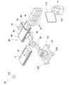
- the robot hand 50 includes a base 52 attached to the tip of the robot arm 30, a conveyor 60 fixed to the base 52, and a cardboard box W on a transfer surface 68 of the conveyor 60. And a holding mechanism 70 for holding and placing the.
- the base 52 has a rectangular bottom plate 54 as viewed in its thickness direction, a side plate 56 a rising from one edge in the width direction of the bottom plate 54, and the other in the width direction of the bottom plate 54. And a side plate 56b rising from the side edge.
- Each of the side plates 56a and 56b is rectangular when viewed in the thickness direction thereof, and has the same shape as each other.
- the conveyor 60 is configured as a belt conveyor.
- the conveyor 60 includes a plurality of rollers 62 arranged adjacent to each other in the transport direction, a pair of shafts 64 a and 64 b for supporting the rotation shafts of the plurality of rollers 62, and a plurality of rollers 62 in a ring shape.
- This is a known structure including a transport belt 66 that is stretched, and an electric motor (not shown) for rotating at least one of the plurality of rollers 62.
- the holding mechanism 70 includes a rotating shaft 72 arranged to extend along the conveyor 60 in the transport direction of the conveyor 60, a swing unit 80 attached to the rotating shaft 72, It has four suction portions 86 (holding portions) that are provided on the upstream side in the transport direction of the swinging portion 80 in the transport direction (that is, the transport direction of the conveyor 60) and that attract and hold the cardboard boxes W.
- the rotating shaft 72 is provided along an edge in the width direction of the conveyor 60, and is extendable and contractible in the transport direction.
- the rotating shaft 72 has a structure as a piston that protrudes from the inside of a rectangular parallelepiped cylinder 74 provided along the edge in the width direction of the conveyor 60 toward the upstream side in the transport direction. That is, in the appearance of the robot 20, the portion of the rotary shaft 72 protruding from the cylinder 74 to the upstream side in the transport direction (that is, the portion visible from the outside) can expand and contract along the transport direction. It can reciprocate along the transport direction.
- the swinging portion 80 is formed in a plate shape, and is attached to the rotating shaft 72 such that its thickness direction matches the transport direction. Specifically, the tip of the rotating shaft 72 is attached to the base end of the main surface of the swinging unit 80 located downstream in the transport direction.
- the swing portion 80 has both main surfaces having a longitudinal dimension.
- the swinging unit 80 can reciprocate in the transport direction by being attached to the rotating shaft 72. Specifically, the swinging unit 80 is capable of reciprocating in the transport direction from a position further upstream than the upstream end of the conveyor 60 to a position at the center of the conveyor 60 in the transport direction.
- the swing unit 80 is attached to the rotating shaft 72, and a plane in which a width direction orthogonal to the transport direction intersects the transport direction and a height direction orthogonal to the width direction. Swingable above. More specifically, the swing unit 80 has a range from a work conveyance posture extending in the width direction of the conveyor 60 on the plane to a work avoidance posture extending in the height direction of the conveyor 60 (ie, a rotation angle of 90 °). Can be pivoted about the rotation shaft 72.
- each of the four suction parts 86 is formed in a hollow tapered shape, and the tapered tip is attached to the swing part 80.
- the four suction units 86 are respectively arranged in a 2 ⁇ 2 matrix, and are arranged at the front end of the main surface on the upstream side in the transport direction of the swing unit 80. It is attached.
- Each of the four suction units 86 is connected to a vacuum generator (not shown), so that the inside is in a negative pressure state.
- the four suction parts 86 can cooperate and hold one cardboard box W by sucking the side surface of the cardboard box W by the negative pressure.
- the robot control device 90 controls the robot arm 30, the conveyor 60, and the holding mechanism 70 based on operation information from the operation unit 110 in accordance with a program stored in a storage unit (not shown) in advance. Control the operation of.
- the specific configuration of the robot control device 90 is not particularly limited.
- the configuration may be realized by a known processor (CPU or the like) operating according to a program stored in a storage unit (memory or the like). Good.
- the operation unit 110 is installed at a predetermined distance from the robot 20 and the AGV 120 in order to remotely control the robot 20 and the AGV 120 based on a manual command value from the operator P.
- a specific configuration of the operation unit 110 is not particularly limited, for example, a configuration that receives a displacement of a steering wheel as a command value or a configuration that receives a button press or the like as a command value may be used. Alternatively, a configuration of a touch panel that receives, as a command value, pressing of a display on a screen or the like may be employed.
- the operation unit 110 may be configured to receive a voice as a command value, or may be configured differently.
- the operation unit 110 receives a manual command value from the operator P, generates operation information, and transmits the operation information to the robot control device 90 and the AGV control device 128.
- Imaging device 112 The imaging device 112 is provided to capture the working status of the robot 20 and the AGV 120 and acquire moving image information.
- the configuration of the imaging device 112 is not particularly limited, for example, the imaging device 112 may be configured as a known video camera.
- the output device 114 is configured as a display device for outputting moving image information captured by the imaging device 112.
- the specific configuration of the output device 114 is not particularly limited, for example, the output device 114 may be configured as a liquid crystal display (Liquid Crystal Display), may be configured as an organic EL display (Organic Electro-Luminescence Display), or , And other devices.
- the AGV 120 (automated guided vehicle) controls the operation of the AGV 120, a vehicle body 122 formed in a plate shape and having a base end of the robot arm 30 fixed to the upper surface thereof, a plurality of wheels 124 attached to the bottom surface of the vehicle body 122.
- the AGV control device 128 controls the operation of the AGV 120 based on operation information from the operation unit 110 and the like according to a program stored in a storage unit (not shown) in advance.
- the specific configuration of the AGV control device 128 is not particularly limited.
- the configuration may be realized by a known processor (CPU or the like) operating according to a program stored in a storage unit (memory or the like). Good.
- the AGV control device 128 may detect, for example, a weak induced current from an electric wire buried in a floor at a work site, and control the operation of the AGV 120 based on the detected value. At this time, operation information from the operation unit 110 may be received as needed.
- Example of transport work An example of a transfer operation performed by the robot system 10 according to the embodiment will be described.
- an example of an operation of transporting a plurality of stacked cardboard boxes W one by one to a stationary conveyor C using the robot system 10 will be described.
- the operator P inputs a command value to the operation unit 110 while grasping the operation status of the robot 20 and the AGV 120 based on the moving image information output from the output device 114.
- the moving image information output from the output device 114 is obtained by imaging the working conditions of the robot 20 and the AGV 120 using the imaging device 112.
- the operator P stops the transport belt 66 of the conveyor 60 using the operation unit 110. Further, as shown in FIG. 3A, by extending the rotation shaft 72, the swing unit 80 is positioned further upstream than the upstream end of the conveyor 60. Further, the operator P uses the operation unit 110 to rotate the rotating shaft 72 as shown in FIG. 4A, thereby swinging the swinging unit 80 and holding the swinging unit 80 in the work holding posture. And
- the operator P operates the AGV 120 using the operation unit 110 to move the robot 20 (and the AGV 120) to the vicinity of the plurality of cardboard boxes W to be transported.
- the operator P uses the operation unit 110 to move the four suction units 86 provided on the main surface on the upstream side of the swing unit 80 to one of the plurality of
- the posture of the robot arm 30 is changed so as to come into contact with the side surface of the box W (hereinafter, simply referred to as “the uppermost cardboard box W”).
- the operator P uses the operation unit 110 so that the upstream end of the conveying surface of the conveyor 60 extends in the vicinity of the lower end of the side surface of the uppermost cardboard box W and in parallel with the lower end.
- the posture of the robot arm 30 is adjusted.
- the operator P drives a vacuum generator (not shown) by using the operation unit 110 to bring the four suction units 86 into a negative pressure state.
- the suction section 86 can hold the uppermost cardboard box W by adsorbing to the side surface of the uppermost cardboard box W.
- the operator P uses the operation unit 110 to shrink the rotating shaft 72 to swing the swinging unit 80 to the central position in the transport direction of the conveyor 60. .
- the cardboard box W held by the suction unit 86 is drawn into the transport surface 68 of the conveyor 60 and placed on the transport surface 68.
- the operator P uses the operation unit 110 to position the robot arm 30 so that the transfer surface 68 of the conveyor 60 is continuous with the transfer surface of the stationary conveyor C upstream of the transfer surface of the stationary conveyor C.
- the posture of the robot arm 30 is adjusted such that the downstream edge of the conveyor 60 approaches above the upstream end portion of the transfer surface of the stationary conveyor C, and the width direction of the upstream end portion is parallel to the upstream end portion. I do.
- the operator P uses the operation unit 110 to change the posture of the robot arm 30. May be changed, and the AGV 120 may be moved.
- the operator P drives the conveyor belt 66 of the conveyor 60 using the operation unit 110.
- the cardboard box W placed on the transport surface 68 of the conveyor 60 moves to the downstream side of the transport surface 68, and further, from the downstream end of the transport surface 68 to the transport surface of the stationary conveyor C. Delivered to the upstream end.
- the robot system 10 can transfer all of the plurality of stacked cardboard boxes W to the transfer surface of the stationary conveyor C.
- the stationary conveyor C may be configured as a belt conveyor similarly to the conveyor 60.
- the belt conveyor may have a known structure.
- the stationary conveyor C receives the cardboard box W from the conveyor 60 at an upstream portion thereof, the stationary conveyor C further conveys the cardboard box W to a desired destination.
- the suction unit 86 provided in the swing unit 80 holds the cardboard box W while holding the conveyor 60. Can be pulled in and placed on the transfer surface 68. Further, since the swing portion 80 can swing around the rotation shaft 72 on a plane where the width direction and the height direction of the conveyor 60 intersect, after the cardboard box W is placed on the transport surface 68 of the conveyor 60, By swinging the swing unit 80, the swing unit 80 can be set to the work avoiding posture (that is, the swing unit 80 swings to a position where the conveyance of the cardboard box W on the conveyor 60 is not hindered). Can be done). As described above, the cardboard box W can be held and placed on the transport surface 68 of the conveyor 60 by the holding mechanism 70 having a simple configuration.
- the swing unit 80 is formed in a plate shape, and is attached to the rotating shaft 72 so that the thickness direction thereof coincides with the transport direction of the conveyor 60. It is attached to the main surface existing on the upstream side in the transport direction. According to such a structure, the holding mechanism 70 can have a simpler configuration.
- the rotary shaft 72 is provided along the edge of the conveyor 60 in the width direction, so that the entire structure of the robot hand 50 can be made compact. After the cardboard box W is placed on the conveying surface 68 of the conveyor 60, the swinging unit 80 is swung to easily set the work avoiding posture.
- the holding unit is configured as the suction unit 86, for example, even when holding one cardboard box W from a plurality of cardboard boxes W stacked without gaps, the one cardboard box W By adsorbing the side surface of the box W, the one cardboard box W can be easily held without being hindered by another cardboard box W.
- the robot 20 according to the present embodiment has the same effect as the robot hand 50 by including the robot hand 50 described above.
- the robot 20 according to the present embodiment is configured as a vertical articulated robot, the robot arm 30 can easily take a desired posture, and as a result, the effects of the present invention can be remarkable.
- the robot 20 according to the present embodiment has six joint axes, the robot arm 30 can easily take a desired posture, and as a result, the effect of the present invention can be remarkable.
- the robot system 10 can remotely control the robot 20 having the robot hand 50 and the robot arm 30 using the operation unit 110. As a result, it is possible to provide the robot system 10 capable of transporting the cardboard boxes W by a movable conveyor without limiting the installation location.
- the robot system 10 further includes an imaging device 112 for imaging the work situation of the robot 20, and an output device 114 for outputting moving image information (information) captured by the imaging device 112.
- an imaging device 112 for imaging the work situation of the robot 20, and an output device 114 for outputting moving image information (information) captured by the imaging device 112.
- the operator P can input a command value to the operation unit 110 while accurately grasping the work status of the robot 20 based on the moving image information output from the output device 114.
- the robot system 10 further includes an AGV 120 (automated guided vehicle) to which the base end of the robot arm 30 is fixed, for example, the distance between the stacked plurality of cardboard boxes W and the stationary conveyor C is reduced.
- AGV 120 automated guided vehicle
- the transfer operation can be performed smoothly. That is, since the installation place is not further limited, the effect of the present invention can be remarkable.
- the work to be transported is the cardboard box W
- the present invention is not limited to this case, and the work may be another object having a predetermined shape (for example, a member and a package used for assembling a machine. Foods, etc.), rocks or fried foods not having a predetermined shape.
- the cardboard box W is placed on the transport surface 68 of the conveyor 60, and the transport surface 68 of the conveyor 60 is continuous with the transport surface of the stationary conveyor C upstream of the transport surface of the stationary conveyor C.
- the case where the conveyor belt 66 of the conveyor 60 is driven for the first time after the posture of the robot arm 30 is changed and the swinging unit 80 is changed to the work avoiding posture has been described.
- the present invention is not limited to this case, and the transport operation may be performed while the transport belt 66 of the conveyor 60 is constantly driven. Thereby, the operation of transporting the plurality of cardboard boxes W one by one can be performed in a short time.
- the robot system 10 includes the robot 20, the operation unit 110, the imaging device 112, the output device 114, and the AGV 120 as illustrated in the block diagram of FIG. 2 has been described.
- the present invention is not limited to this case, and the robot system 10 may further include another configuration.
- the robot system 10 may further include a stationary conveyor C to which the cardboard box W is transported in the above embodiment.
- the operator P may be configured to control the operation of the stationary conveyor C using the operation unit 110.
- the conveyor 60 may be attached to the base 52 so as to be rotatable with respect to the base 52 on a plane where the conveying direction and the height direction intersect.
- the conveyor 60 may be provided with a pair of rails on the base 52 and attached to the base 52 so as to be able to move on the rails.
- the robot control device 90 may further control the operation of the base 52.
- the holding unit includes the four suction units 86 that suck and hold the cardboard box W (work), but the invention is not limited thereto.
- the shape of each of the four suction portions 86 is not limited to the hollow tapered shape, and may be a hollow rectangular parallelepiped shape, a cylindrical shape, or another shape.
- the holding unit may be configured as a grip unit that grips and holds the work, or may be configured as a mounting unit that mounts and holds the work on its upper surface, or other configurations. It may be.
- the conveyor 60 is configured as a belt conveyor, but the present invention is not limited to this.
- the conveyor 60 may be configured as a roller conveyor, or may be configured as another conveyor.
- the rotating shaft 72 can expand and contract in the transport direction of the conveyor 60 on the appearance of the robot 20 but in fact can reciprocate in the transport direction by the cylinder 74 . It is not limited to.
- the rotating shaft 72 is constituted by a hollow cylindrical member and a cylindrical member inserted coaxially so as to be able to reciprocate in the axial direction inside the cylindrical member, so that the conveying direction of the conveyor 60 is changed. May be stretchable along.
- a part of the cylindrical member may protrude from the tip of the hollow cylindrical member in a state where the rotating shaft 72 is most contracted, and the swinging portion 80 may be attached to the protruding portion.
- the rotary shaft 72 does not use the cylinder 74 (for example, by being connected to another member that can reciprocate in the transport direction of the conveyor 60), and also in the appearance of the robot 20, the transport direction of the conveyor 60. It may be reciprocable.
- the rotating shaft 72 is parallel to the conveying surface 68 of the conveyor 60 when viewed in the width direction above the conveyor 60, and in the width direction of the conveyor 60 when viewed in the height direction from above the conveyor 60. May be arranged so as to extend in the transport direction at the same position as the center line in.
- the swinging portion 80 has its base end attached to the rotating shaft 72, so that, for example, one side in the width direction of the conveyor 60 on a plane where the width direction and the height direction intersect. From the work avoiding posture extending in the width direction of the conveyor 60 to the work avoiding posture extending to the other side in the width direction of the conveyor 60 (that is, the rotation angle of 180 ° on the plane). ) May be swingable about the rotation shaft 72.
- the robot 20 may be configured as a polar coordinate robot, may be configured as a cylindrical coordinate robot, may be configured as a rectangular coordinate robot, or may be configured as a horizontal articulated robot. Or may be configured as another robot.
- the robot arm 30 has six joint axes, but the present invention is not limited to this.
- the robot arm 30 may have seven or more joint axes.
- the robot arm 30 may have one or more and five or less joint axes.
- the robot system 10 includes the imaging device 112 and the output device 114 has been described, but is not limited thereto.
- the robot system 10 may not include the imaging device 112 and the output device 114, and may be configured so that the operator P visually checks the work status of the robot 20 and the AGV 120. Thereby, the configuration of the robot system 10 can be further simplified.
- the oscillating portion 80 is formed in a rectangular plate shape when viewed in the thickness direction, and is attached to the rotating shaft 72 so that the thickness direction coincides with the transport direction of the conveyor 60.
- the part 86 is attached to the main surface existing on the upstream side in the transport direction of the swing part 80
- the present invention is not limited to this.
- the swing unit 80 can swing to the work holding posture and the work avoiding posture by being attached to the rotating shaft 72, and the suction unit 86 (holding unit) is located on the upstream side in the transport direction. Any shape can be used as long as it can be attached to the part.
- the thickness direction when viewed in the thickness direction, it may be formed in a triangular shape, a pentagonal or more polygonal shape, or a square plate shape, may be formed in a columnar shape, or may be formed in a pyramid or a cone shape. Or may be formed in another shape.
- the robot system 10 causes the operator P to input a command value using the operation unit 110 and operates the robot 20 and the AGV 120 based on the command value has been described, but the present invention is not limited to this.
- the robot system 10 may be configured as a fully automatic system that does not include the operation unit 110.
- a proximity sensor is provided at the tip of the robot arm 30, and the robot controller 90 controls the robot arm 30 and the robot hand 50 based on the detection value of the proximity sensor.
- the operation may be controlled, or a camera may be provided at the tip of the robot arm 30, and the robot controller 90 controls the operation of each of the robot arm 30 and the robot hand 50 based on an analysis value of image information by the camera. May be.
- a weak induced current may be detected from an electric wire buried on the floor at the work site, and the operation of the AGV 120 may be controlled by the AGV control device 128 based on the detected value or the like.
Landscapes
- Engineering & Computer Science (AREA)
- Mechanical Engineering (AREA)
- Robotics (AREA)
- Manipulator (AREA)
- Specific Conveyance Elements (AREA)
Abstract
Description
図1は、本実施形態に係るロボットシステムを用いて段ボール箱の搬送作業を行っている様子を示す概略図である。また、図2は、同ロボットシステムの全体構成を示すブロック図である。図1に示すように、本実施形態に係るロボットシステム10は、被包装物を包装した状態で封がされた段ボール箱W(ワーク)の搬送作業を行う。具体的には、ロボットシステム10は、積載された複数の段ボール箱Wを1つずつ据置型コンベヤCまで搬送する作業を行う。
図1、2に示すように、ロボット20は、ロボットアーム30と、当該ロボットアーム30の先端に取り付けられるロボットハンド50と、ロボットアーム30及びロボットハンド50の動作を制御するためのロボット制御装置90と、を備える。ロボット20は、垂直多関節型ロボットとして構成されている。
図3は、本実施形態に係るロボットの側面図であり、(A)が揺動部を前方に移動させたときの図、(B)が揺動部を後方に移動させたときの図である。図3に示すように、ロボットアーム30は、6つの関節軸JT1~JT6と、これらの関節軸によって順次連結される6つのリンク33a~33fと、を有する多関節アームである。
図4は、本実施形態に係るロボットハンドの正面図であり、(A)が揺動部をワーク保持姿勢としたときの図、(B)が揺動部をワーク回避姿勢としたときの図である。図3、4に示すように、ロボットハンド50は、ロボットアーム30の先端に取り付けられるベース52と、当該ベース52に対して固定されるコンベヤ60と、当該コンベヤ60の搬送面68に段ボール箱Wを保持して載置する保持機構70と、を備える。
図3、4に示すように、ベース52は、その厚み方向に見て矩形状の底板54と、底板54の幅方向における一方側の端縁から立ち上がる側板56aと、底板54の幅方向における他方側の端縁から立ち上がる側板56bと、を有する。側板56a、56bは、それぞれ、その厚み方向に見て矩形状であり、互いに同じ形状を有する。
図3に示すように、コンベヤ60は、ベルトコンベヤとして構成される。コンベヤ60は、搬送方向において互いに隣接して並列される複数のローラ62と、複数のローラ62それぞれの回転軸を軸支するための一対のシャフト64a、64bと、複数のローラ62に輪状にして張架される搬送ベルト66と、複数のローラ62のうちの少なくとも一つを回転駆動するための図示しない電気モータと、を有する公知の構造である。
図3、4に示すように、保持機構70は、コンベヤ60に沿って当該コンベヤ60の搬送方向に延びるように配置される回転軸72と、当該回転軸72に取り付けられる揺動部80と、揺動部80の前記搬送方向(すなわち、コンベヤ60の搬送方向)における上流側に設けられ、段ボール箱Wを吸着して保持する4個の吸着部86(保持部)と、を有する。
図2に示すように、ロボット制御装置90は、操作部110からの操作情報などに基づき、予め記憶部(図示せず)に格納されるプログラムに従って、ロボットアーム30、コンベヤ60、及び保持機構70の動作を制御する。ロボット制御装置90についての具体的な構成は特に限定されないが、例えば、公知のプロセッサ(CPU等)が記憶部(メモリ等)に格納されるプログラムに従って動作することで実現される構成であってもよい。
図1に示すように、操作部110は、オペレータPからの手動による指令値に基づき、ロボット20及びAGV120を遠隔操作するために、ロボット20及びAGV120から所定の距離だけ離間して設置される。
撮像装置112は、ロボット20及びAGV120の作業状況を撮像して動画情報を取得するために設けられる。撮像装置112の構成は特に限定されないが、例えば、公知のビデオカメラとして構成されてもよい。
出力装置114は、撮像装置112で撮像された動画情報を出力するための表示装置として構成される。出力装置114の具体的な構成は特に限定されないが、例えば、液晶ディスプレイ(Liquid Crystal Display)として構成されてもよいし、有機ELディスプレイ(Organic Electro-Luminescence Display)として構成されてもよいし、又は、その他の装置として構成されてもよい。
AGV120(無人搬送車)は、板状に形成されその上面にロボットアーム30の基端が固定される車体122と、当該車体122の底面に取り付けられる複数の車輪124と、AGV120の動作を制御するためのAGV制御装置128と、を有する。
本実施形態に係るロボットシステム10によって行われる搬送作業の一例について説明する。ここでは、上記ロボットシステム10を用いて、積載された複数の段ボール箱Wを1つずつ据置型コンベヤCまで搬送する作業の一例について説明する。なお、以下の搬送作業の一例では、オペレータPは、出力装置114から出力される動画情報に基づき、ロボット20及びAGV120の作業状況を把握しつつ、操作部110に対して指令値を入力してもよい。ここで、出力装置114から出力される動画情報は、撮像装置112を用いてロボット20及びAGV120の作業状況を撮像したものである。
本実施形態に係るロボットハンド50は、ロボットアーム30の先端にコンベヤ60が固定されているので、ロボットアーム30の先端が移動可能な範囲でコンベヤ60を移動させることができる。その結果、設置場所が限定的にならずに、移動可能なコンベヤ60によって段ボール箱W(ワーク)を搬送することが可能な、ロボットハンド50を提供することができる。
上記説明から、当業者にとっては、本発明の多くの改良や他の実施形態が明らかである。したがって、上記説明は、例示としてのみ解釈されるべきであり、本発明を実行する最良の態様を当業者に教示する目的で提供されたものである。本発明の精神を逸脱することなく、その構造及び/又は機能の詳細を実質的に変更できる。
20 ロボット
30 ロボットアーム
31 第1アーム部
32 第2アーム部
33 リンク
50 ロボットハンド
52 ベース
54 底板
56 側板
60 コンベヤ
62 ローラ
64 シャフト
66 搬送ベルト
68 搬送面
70 保持機構
72 回転軸
74 シリンダ
80 揺動部
86 吸着部
90 ロボット制御装置
110 操作部
112 撮像装置
114 出力装置
120 AGV
122 車体
124 車輪
128 AGV制御装置
JT 関節軸
C 据置型コンベヤ
P オペレータ
W 段ボール箱
Claims (13)
- ロボットアームの先端に取り付けられるベースと、
前記ベースに対して固定されるコンベヤと、
前記コンベヤの搬送面にワークを保持して載置する保持機構と、
を備えることを特徴とする、ロボットハンド。 - 前記保持機構は、
前記コンベヤに沿って前記コンベヤの搬送方向に延びるように配置され、且つ、前記搬送方向において往復運動可能又は伸縮可能な回転軸と、
前記回転軸に取り付けられることで、前記搬送方向において往復運動可能であり、且つ、前記搬送方向に直交する幅方向と前記搬送方向及び前記幅方向に直交する高さ方向とが交わる平面上で前記回転軸を中心として揺動可能な揺動部と、
前記揺動部の前記搬送方向における上流側に設けられ、前記ワークを保持する保持部と、
を有する、請求項1に記載のロボットハンド。 - 前記揺動部は、板状に形成されており、その厚み方向が前記搬送方向と一致するように前記回転軸に取り付けられ、
前記保持部は、前記揺動部の前記搬送方向における上流側に存する主面に取り付けられる、請求項2に記載のロボットハンド。 - 前記回転軸は、前記コンベヤの幅方向における縁部に沿って設けられる、請求項2又は3に記載のロボットハンド。
- 前記保持部は、前記ワークを吸着して保持する吸着部として構成される、請求項2乃至4のいずれかに記載のロボットハンド。
- 前記コンベヤはベルトコンベヤとして構成される、請求項1乃至5のいずれかに記載のロボットハンド。
- 請求項1乃至6のいずれかに記載のロボットハンドと、
前記ロボットハンドが取り付けられるロボットアームと、
前記ロボットハンド及び前記ロボットアームの動作を制御するためのロボット制御装置と、を備えることを特徴とする、ロボット。 - 垂直多関節型ロボットとして構成される、請求項7に記載のロボット。
- 前記ロボットアームは6つ以上の関節軸を有する、請求項7又は8に記載のロボット。
- 請求項7乃至9のいずれかに記載のロボットを備えることを特徴とする、ロボットシステム。
- 前記ロボットを遠隔操作するための操作部をさらに備える、請求項10に記載のロボットシステム。
- 前記ロボットの作業状況を撮像するための撮像装置と、
前記撮像装置で撮像した情報を出力するための出力装置と、をさらに備える、請求項10又は11に記載のロボットシステム。 - 前記ロボットアームの基端が固定される無人搬送車をさらに備える、請求項10乃至12のいずれかに記載のロボットシステム。
Priority Applications (4)
| Application Number | Priority Date | Filing Date | Title |
|---|---|---|---|
| CN201980054628.0A CN112566858B (zh) | 2018-08-23 | 2019-08-19 | 机械手、机器人以及机器人系统 |
| DE112019004218.1T DE112019004218B4 (de) | 2018-08-23 | 2019-08-19 | Roboterhand, Roboter und Robotersystem |
| KR1020217007810A KR20210044845A (ko) | 2018-08-23 | 2019-08-19 | 로봇 핸드, 로봇 및 로봇 시스템 |
| US17/180,879 US11958187B2 (en) | 2018-08-23 | 2021-02-22 | Robot hand, robot and robot system |
Applications Claiming Priority (2)
| Application Number | Priority Date | Filing Date | Title |
|---|---|---|---|
| JP2018156231A JP7117192B2 (ja) | 2018-08-23 | 2018-08-23 | ロボットハンド、ロボット及びロボットシステム |
| JP2018-156231 | 2018-08-23 |
Related Child Applications (1)
| Application Number | Title | Priority Date | Filing Date |
|---|---|---|---|
| US17/180,879 Continuation US11958187B2 (en) | 2018-08-23 | 2021-02-22 | Robot hand, robot and robot system |
Publications (1)
| Publication Number | Publication Date |
|---|---|
| WO2020040102A1 true WO2020040102A1 (ja) | 2020-02-27 |
Family
ID=69593145
Family Applications (1)
| Application Number | Title | Priority Date | Filing Date |
|---|---|---|---|
| PCT/JP2019/032330 Ceased WO2020040102A1 (ja) | 2018-08-23 | 2019-08-19 | ロボットハンド、ロボット及びロボットシステム |
Country Status (7)
| Country | Link |
|---|---|
| US (1) | US11958187B2 (ja) |
| JP (1) | JP7117192B2 (ja) |
| KR (1) | KR20210044845A (ja) |
| CN (1) | CN112566858B (ja) |
| DE (1) | DE112019004218B4 (ja) |
| TW (1) | TWI706839B (ja) |
| WO (1) | WO2020040102A1 (ja) |
Cited By (3)
| Publication number | Priority date | Publication date | Assignee | Title |
|---|---|---|---|---|
| CN111376293A (zh) * | 2020-04-15 | 2020-07-07 | 珠海格力精密模具有限公司 | 机器人的夹具和机器人 |
| WO2020209334A1 (ja) * | 2019-04-09 | 2020-10-15 | 川崎重工業株式会社 | ロボットハンド、ロボット及びロボットシステム |
| WO2020209335A1 (ja) * | 2019-04-09 | 2020-10-15 | 川崎重工業株式会社 | ロボットハンド、ロボット及びロボットシステム |
Families Citing this family (10)
| Publication number | Priority date | Publication date | Assignee | Title |
|---|---|---|---|---|
| US11130242B1 (en) * | 2020-01-23 | 2021-09-28 | Amazon Technologies, Inc. | Container transporter |
| US20210260626A1 (en) * | 2020-02-26 | 2021-08-26 | InTunes Products, LLC | Package handling and sorting system |
| TWI820454B (zh) * | 2021-07-19 | 2023-11-01 | 財團法人工業技術研究院 | 夾持裝置以及夾持目標物件的方法 |
| KR102693910B1 (ko) * | 2021-11-15 | 2024-08-12 | 주식회사 에스티씨엔지니어링 | 로봇 팔 장치 및 이를 구비하는 화물 하차 자동화 머신 |
| KR102762710B1 (ko) * | 2021-11-15 | 2025-02-07 | 주식회사 에스티씨엔지니어링 | 화물 하차 자동화 방법 및 이를 수행하기 위한 컴퓨팅 장치 |
| CN114505969A (zh) * | 2022-03-17 | 2022-05-17 | 华侨大学 | 一种晶棒自动化运输装置及其方法 |
| KR102735078B1 (ko) * | 2022-08-19 | 2024-11-28 | 주식회사 에스티씨엔지니어링 | 화물 하차 자동화 방법 및 이를 수행하기 위한 화물 하차 자동화 머신 |
| CN115123837A (zh) * | 2022-08-30 | 2022-09-30 | 常州奥智高分子集团股份有限公司 | 一种扩散板半成品堆料机 |
| WO2024242211A1 (ko) * | 2023-05-22 | 2024-11-28 | 주식회사 에스티씨엔지니어링 | 로봇 팔 장치 및 이를 구비하는 화물 하차 자동화 머신 |
| WO2024242212A1 (ko) * | 2023-05-22 | 2024-11-28 | 주식회사 에스티씨엔지니어링 | 화물 하차 자동화 방법 및 이를 수행하기 위한 컴퓨팅 장치 |
Citations (5)
| Publication number | Priority date | Publication date | Assignee | Title |
|---|---|---|---|---|
| JPS61282226A (ja) * | 1985-06-10 | 1986-12-12 | Hitachi Ltd | 貨物自動積付方式 |
| JPS62136444U (ja) * | 1986-02-21 | 1987-08-27 | ||
| JP2001062762A (ja) * | 1999-08-24 | 2001-03-13 | Denso Corp | 移動ロボット |
| JP2016055995A (ja) * | 2014-09-10 | 2016-04-21 | 株式会社東芝 | 荷役装置及び把持装置 |
| JP2018039534A (ja) * | 2016-09-08 | 2018-03-15 | ミツイワ株式会社 | 物品搬送装置 |
Family Cites Families (12)
| Publication number | Priority date | Publication date | Assignee | Title |
|---|---|---|---|---|
| DE3739865C1 (de) * | 1987-11-25 | 1988-12-22 | Salzgitter Maschb Gmbh | Verfahren und Vorrichtung zum Entladen von Stueckguetern |
| JP2855766B2 (ja) * | 1990-03-29 | 1999-02-10 | 株式会社高岳製作所 | ハンドリングロボット |
| JPH0784258B2 (ja) * | 1992-05-20 | 1995-09-13 | 村田機械株式会社 | ピッキング装置 |
| JPH0815939B2 (ja) * | 1992-09-09 | 1996-02-21 | 村田機械株式会社 | ピッキングロボット |
| JP3788040B2 (ja) * | 1998-06-24 | 2006-06-21 | 日産自動車株式会社 | ワーク搬送装置およびワーク搬送方法 |
| CN104249366B (zh) * | 2013-06-28 | 2016-08-10 | 国家电网公司 | 平面多关节机器人 |
| US9785911B2 (en) * | 2013-07-25 | 2017-10-10 | I AM Robotics, LLC | System and method for piece-picking or put-away with a mobile manipulation robot |
| US9498887B1 (en) * | 2014-07-24 | 2016-11-22 | X Development Llc | Two-faced linearly actuated gripper |
| EP3865254B1 (en) * | 2014-08-27 | 2025-10-22 | Intelligrated Headquarters LLC | Robotic carton unloader |
| KR20160055995A (ko) | 2014-11-11 | 2016-05-19 | (주)쌍마판넬 | 건축용 판넬의 구조체 |
| JP6559413B2 (ja) | 2014-11-13 | 2019-08-14 | 株式会社東芝 | 移載装置及び荷物取出方法 |
| JP2018122945A (ja) * | 2017-01-30 | 2018-08-09 | 株式会社東芝 | 可変型物品保持装置、移載装置、ロボットハンドリングシステム、および移載装置の制御方法 |
-
2018
- 2018-08-23 JP JP2018156231A patent/JP7117192B2/ja active Active
-
2019
- 2019-08-19 KR KR1020217007810A patent/KR20210044845A/ko not_active Withdrawn
- 2019-08-19 CN CN201980054628.0A patent/CN112566858B/zh active Active
- 2019-08-19 DE DE112019004218.1T patent/DE112019004218B4/de active Active
- 2019-08-19 WO PCT/JP2019/032330 patent/WO2020040102A1/ja not_active Ceased
- 2019-08-23 TW TW108130226A patent/TWI706839B/zh not_active IP Right Cessation
-
2021
- 2021-02-22 US US17/180,879 patent/US11958187B2/en active Active
Patent Citations (5)
| Publication number | Priority date | Publication date | Assignee | Title |
|---|---|---|---|---|
| JPS61282226A (ja) * | 1985-06-10 | 1986-12-12 | Hitachi Ltd | 貨物自動積付方式 |
| JPS62136444U (ja) * | 1986-02-21 | 1987-08-27 | ||
| JP2001062762A (ja) * | 1999-08-24 | 2001-03-13 | Denso Corp | 移動ロボット |
| JP2016055995A (ja) * | 2014-09-10 | 2016-04-21 | 株式会社東芝 | 荷役装置及び把持装置 |
| JP2018039534A (ja) * | 2016-09-08 | 2018-03-15 | ミツイワ株式会社 | 物品搬送装置 |
Cited By (7)
| Publication number | Priority date | Publication date | Assignee | Title |
|---|---|---|---|---|
| WO2020209334A1 (ja) * | 2019-04-09 | 2020-10-15 | 川崎重工業株式会社 | ロボットハンド、ロボット及びロボットシステム |
| WO2020209335A1 (ja) * | 2019-04-09 | 2020-10-15 | 川崎重工業株式会社 | ロボットハンド、ロボット及びロボットシステム |
| JP2020171982A (ja) * | 2019-04-09 | 2020-10-22 | 川崎重工業株式会社 | ロボットハンド、ロボット及びロボットシステム |
| JP2020171983A (ja) * | 2019-04-09 | 2020-10-22 | 川崎重工業株式会社 | ロボットハンド、ロボット及びロボットシステム |
| JP7220116B2 (ja) | 2019-04-09 | 2023-02-09 | 川崎重工業株式会社 | ロボットハンド、ロボット及びロボットシステム |
| JP7220115B2 (ja) | 2019-04-09 | 2023-02-09 | 川崎重工業株式会社 | ロボットハンド、ロボット及びロボットシステム |
| CN111376293A (zh) * | 2020-04-15 | 2020-07-07 | 珠海格力精密模具有限公司 | 机器人的夹具和机器人 |
Also Published As
| Publication number | Publication date |
|---|---|
| JP7117192B2 (ja) | 2022-08-12 |
| CN112566858A (zh) | 2021-03-26 |
| US11958187B2 (en) | 2024-04-16 |
| DE112019004218T5 (de) | 2021-06-02 |
| TW202017720A (zh) | 2020-05-16 |
| TWI706839B (zh) | 2020-10-11 |
| JP2020028951A (ja) | 2020-02-27 |
| KR20210044845A (ko) | 2021-04-23 |
| US20210187727A1 (en) | 2021-06-24 |
| CN112566858B (zh) | 2022-07-05 |
| DE112019004218B4 (de) | 2025-12-18 |
Similar Documents
| Publication | Publication Date | Title |
|---|---|---|
| WO2020040102A1 (ja) | ロボットハンド、ロボット及びロボットシステム | |
| US11845621B2 (en) | Robot and robot system having the same | |
| JP6942576B2 (ja) | 搬送装置 | |
| TWI864588B (zh) | 裝載與卸載卡車及其他集裝箱之機器人系統、控制一機器人系統之方法、及控制一機器人系統之電腦程式產品 | |
| CN103240591B (zh) | 装配设备和装配方法 | |
| US10457490B2 (en) | Transfer apparatus and holding apparatus | |
| CN100417498C (zh) | 一种搬运码垛机器人 | |
| US20180194009A1 (en) | Robot control device and robotic system | |
| US20140277721A1 (en) | Robot system and method for transferring workpiece | |
| CN109927012A (zh) | 移动抓取机器人和自动取货方法 | |
| EP3290165A2 (en) | Robot control device, robot, and robot system | |
| CN102105375A (zh) | 板状工件的移送设备及移送方法 | |
| CN204658437U (zh) | 带视觉功能的Delta并联机械手 | |
| JP2023027373A (ja) | 把持機構を備えたロボットシステム、及び関連するシステムと方法 | |
| CN103846906A (zh) | 机器人 | |
| WO2018139574A1 (ja) | 搬送システム及びその運転方法 | |
| TW201700234A (zh) | 機器人系統 | |
| CN113573996B (zh) | 机器人手、机器人以及机器人系统 | |
| KR20240175941A (ko) | 빈 피킹 및 선반 피킹이 가능한 하이브리드 그리퍼 | |
| JP2017087306A (ja) | ロボットおよびロボットシステム | |
| JP2023174237A (ja) | パラレルリンクロボット及び物品移載装置 |
Legal Events
| Date | Code | Title | Description |
|---|---|---|---|
| 121 | Ep: the epo has been informed by wipo that ep was designated in this application |
Ref document number: 19851215 Country of ref document: EP Kind code of ref document: A1 |
|
| WWE | Wipo information: entry into national phase |
Ref document number: 112019004218 Country of ref document: DE |
|
| ENP | Entry into the national phase |
Ref document number: 20217007810 Country of ref document: KR Kind code of ref document: A |
|
| WWP | Wipo information: published in national office |
Ref document number: 112019004218 Country of ref document: DE |
|
| 122 | Ep: pct application non-entry in european phase |
Ref document number: 19851215 Country of ref document: EP Kind code of ref document: A1 |
|
| WWG | Wipo information: grant in national office |
Ref document number: 112019004218 Country of ref document: DE |