WO2020040105A1 - Dispositif de sélection, procédé de sélection, et programme de sélection - Google Patents
Dispositif de sélection, procédé de sélection, et programme de sélection Download PDFInfo
- Publication number
- WO2020040105A1 WO2020040105A1 PCT/JP2019/032339 JP2019032339W WO2020040105A1 WO 2020040105 A1 WO2020040105 A1 WO 2020040105A1 JP 2019032339 W JP2019032339 W JP 2019032339W WO 2020040105 A1 WO2020040105 A1 WO 2020040105A1
- Authority
- WO
- WIPO (PCT)
- Prior art keywords
- control
- selection
- information
- mode
- unit
- Prior art date
- Legal status (The legal status is an assumption and is not a legal conclusion. Google has not performed a legal analysis and makes no representation as to the accuracy of the status listed.)
- Ceased
Links
Images


Classifications
-
- G—PHYSICS
- G05—CONTROLLING; REGULATING
- G05D—SYSTEMS FOR CONTROLLING OR REGULATING NON-ELECTRIC VARIABLES
- G05D1/00—Control of position, course, altitude or attitude of land, water, air or space vehicles, e.g. using automatic pilots
- G05D1/10—Simultaneous control of position or course in three dimensions
- G05D1/101—Simultaneous control of position or course in three dimensions specially adapted for aircraft
- G05D1/102—Simultaneous control of position or course in three dimensions specially adapted for aircraft specially adapted for vertical take-off of aircraft
-
- B—PERFORMING OPERATIONS; TRANSPORTING
- B64—AIRCRAFT; AVIATION; COSMONAUTICS
- B64C—AEROPLANES; HELICOPTERS
- B64C13/00—Control systems or transmitting systems for actuating flying-control surfaces, lift-increasing flaps, air brakes, or spoilers
- B64C13/02—Initiating means
- B64C13/16—Initiating means actuated automatically, e.g. responsive to gust detectors
- B64C13/18—Initiating means actuated automatically, e.g. responsive to gust detectors using automatic pilot
-
- B—PERFORMING OPERATIONS; TRANSPORTING
- B64—AIRCRAFT; AVIATION; COSMONAUTICS
- B64U—UNMANNED AERIAL VEHICLES [UAV]; EQUIPMENT THEREFOR
- B64U20/00—Constructional aspects of UAVs
- B64U20/80—Arrangement of on-board electronics, e.g. avionics systems or wiring
- B64U20/87—Mounting of imaging devices, e.g. mounting of gimbals
-
- G—PHYSICS
- G05—CONTROLLING; REGULATING
- G05D—SYSTEMS FOR CONTROLLING OR REGULATING NON-ELECTRIC VARIABLES
- G05D1/00—Control of position, course, altitude or attitude of land, water, air or space vehicles, e.g. using automatic pilots
- G05D1/10—Simultaneous control of position or course in three dimensions
- G05D1/101—Simultaneous control of position or course in three dimensions specially adapted for aircraft
- G05D1/106—Change initiated in response to external conditions, e.g. avoidance of elevated terrain or of no-fly zones
-
- G—PHYSICS
- G06—COMPUTING OR CALCULATING; COUNTING
- G06V—IMAGE OR VIDEO RECOGNITION OR UNDERSTANDING
- G06V20/00—Scenes; Scene-specific elements
- G06V20/10—Terrestrial scenes
- G06V20/17—Terrestrial scenes taken from planes or by drones
-
- B—PERFORMING OPERATIONS; TRANSPORTING
- B64—AIRCRAFT; AVIATION; COSMONAUTICS
- B64U—UNMANNED AERIAL VEHICLES [UAV]; EQUIPMENT THEREFOR
- B64U2101/00—UAVs specially adapted for particular uses or applications
- B64U2101/30—UAVs specially adapted for particular uses or applications for imaging, photography or videography
-
- B—PERFORMING OPERATIONS; TRANSPORTING
- B64—AIRCRAFT; AVIATION; COSMONAUTICS
- B64U—UNMANNED AERIAL VEHICLES [UAV]; EQUIPMENT THEREFOR
- B64U2201/00—UAVs characterised by their flight controls
Definitions
- the present invention relates to movement control of a moving body.
- Multi-copters that levitate and fly with a multi-axis rotor with multiple rotors are easy to handle, so they can be applied to observation and monitoring of objects, and inspection work for infrastructure structures and the like. Examination is underway.
- a multi-copter disclosed in Patent Document 1 has a large number of rotor blade rotors that are evenly distributed and attached to a cylindrical body formed of a composite material made of carbon fiber, a thermosetting synthetic resin, and a metal. Is provided.
- the unmanned aerial vehicle and the mooring device are connected via a mooring line. Then, the unmanned aerial vehicle system enables the control of maintaining the tension of the mooring line to a predetermined condition according to a change in an environmental condition such as a strong wind by cooperating the unmanned aerial vehicle and the mooring device on the ground with each other. .
- Non-Patent Documents 1 to 3 disclose flying robot systems and the like for performing infrastructure inspection.
- Toshiaki Yamashita et al. Development of a flying robot system for infrastructure inspection, Proceedings of the 53rd Aircraft Symposium, 2G06.
- Toshiaki Yamashita et al. Performance Evaluation of Flying Robot System for Infrastructure Inspection, 54th Aircraft Symposium Lecture Paper, 2L09. Michitaro Masazawa et al., Development of Safe Contact Flight System for Flying Robot, 55th Aircraft Symposium Lecture Paper, 1F10.
- Non-Patent Literatures 1 to 3 are intended to inspect the hitting sound of a pier or the like.
- the flying robot brings the tip of the hammer into contact with an object to be inspected, such as a wall surface such as a pier.
- the flying robot drives a hammer mounted on the percussion detector at a certain frequency, and generates a sound by continuously hitting the inspection target with the hammer.
- the flying robot performs a hammering test in a predetermined range of the inspection target by moving the tip at a predetermined speed. Therefore, it is important to be able to achieve both the positional accuracy when the tip is fixed to a designated surface position such as a wall surface and the speed at which the tip moves as set.
- the position and the moving speed of the tip depend on the position and attitude, speed and angular velocity of the flying robot body.
- the control accuracy of the flying robot body itself deteriorates due to the influence of disturbance or the like applied to the distal end portion in contact with the wall surface or the like.
- Non-Patent Documents 1 to 3 are controlled by a general drone, it is possible to achieve both the positioning performance of the distal end portion and the accuracy of moving speed as it is. It is difficult.
- the present invention has an object to provide a selection device and the like that can perform both the positioning control and the movement control of a moving body, which are more suitable for the moving state of the moving body and surrounding conditions.
- the selection device is configured to specify a movement mode related to the movement from surrounding state information indicating a surrounding state of the moving body to be moved, and movement state information indicating a movement state of the moving body.
- the first control mode to perform the first control that is the control of the position and attitude of the moving body
- the second control mode to perform the second control that is the control of the speed and angular velocity of the moving body
- the selection device and the like of the present invention enable both the positioning control and the movement control of the moving body, which are more suitable for the moving state of the moving body and the surrounding conditions.
- the movement can be classified into a case where the position and the attitude are controlled and a case where the speed and the angular velocity are controlled, according to the movement state and the surrounding state of the flying object.
- the flying object of the present embodiment has a control mode related to flight, the first control mode for controlling the position and attitude of the flying object, and the second control mode for controlling the speed and angular velocity of the flying object.
- the switching is performed based on a situation around the flying object such as a wind speed and a wind direction detected by a sensor, and a moving state of the flying object.
- the flying object enables flight control more suitable for the moving condition of the flying object and surrounding conditions.
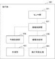
- FIG. 1 is a block diagram illustrating a configuration of a flying object 501 that is an example of the flying object of the present embodiment.
- the flying object 501 is, for example, a multicopter, a drone, or a flying robot.
- the flying object 501 is, more specifically, a multicopter that flies to a position of an inspection target and executes a predetermined inspection on the inspection target, for example.
- the inspection target is, for example, a predetermined portion of a pier.
- the inspection is, for example, a tapping sound inspection for analyzing a sound generated by hitting the portion with a predetermined portion of the flying object 501.
- Non-Patent Documents 1 to 3 disclose such multi-copters that perform a hammering test.
- the flying object 501 includes a movement control unit 201, a drive control unit 206, a work control unit 256, a sensor group 301, a flight enabling unit 401, and a work unit 451.
- the sensor group 301 is a sensor group including sensors installed in each part of the flying object 501.
- the sensors constituting the sensor group 301 are, for example, a wind direction sensor, a wind speed sensor, a barometric pressure sensor, an altitude sensor, an image sensor (camera), a laser distance sensor, a contact sensor, and the like.
- Each sensor sequentially sends the detected sensor information to the movement control unit 201.
- the sensor information is surrounding situation information indicating a situation around the flying object 501.
- the movement control unit 201 selects a control unit that sends control information related to the flight to the drive control unit 206 based on the sensor information sent from the sensor group 301.
- the movement control unit 201 includes a plurality of the control units.
- the control unit is divided into one for controlling, for example, the velocity and the angular velocity of the flying object 501, and one for controlling the position and the attitude of the flying object 501.
- the control unit includes a plurality of control units having different control performances.
- the drive control unit 206 controls the drive of the flight enabling unit 401 by the control unit selected by the movement control unit 201.
- the flight enabling unit 401 executes the flight operation of the flying object 501 in accordance with the drive control by the drive control unit 206.
- the flight enabling unit 401 includes, for example, four or more propellers. In this case, the flight enabling unit 401 performs flying, descent, movement, and attitude change of the flying object 501 by changing the rotation speed of each propeller according to the drive control.
- the work control unit 256 causes the work unit 451 to execute a predetermined work when the movement control unit 201 receives the transmission of the flight mode information indicating that the flight mode is the work mode.
- the work is, for example, the above-described hitting sound of a pier.
- the hitting sound inspection is for hitting a target object at a predetermined portion of the working unit 451 and inspecting a condition such as a sound quality of a generated sound.
- the flying object 501 causes the tip of the percussion inspection machine to come into contact with an object to be inspected, such as a wall of a pier, at the time of the percussion inspection, like the flying robot described in the section of the problem to be solved by the invention. . Then, the flying object 501 generates a sound by driving a hammer mounted on the percussion detector at a certain frequency and continuously hitting the inspection target with the hammer. Further, the flying robot performs a hammering test in a predetermined range of the inspection target by moving the tip at a predetermined speed.
- the work unit 451 executes the work according to an instruction from the work control unit 256.
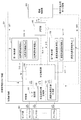
- FIG. 2 is a conceptual diagram showing a configuration example of the movement control unit 201 shown in FIG.
- the movement control unit 201 illustrated in FIG. 2 includes a determination unit 150, a first control unit 151, a second control unit 152, and a selection unit 105.
- the determination unit 150 includes a mode designation unit 101, a position / posture target generation unit 102, a speed angular velocity target generation unit 103, and a state estimation unit 104.
- the first control unit 151 can select any of the position and orientation control systems p1 to pn.
- Each of the position and orientation control systems p1 to pn is a control system that performs only position and orientation control.
- Each position and orientation control system has a different control performance from the other position and orientation control systems.
- the control performance is a performance associated with control accuracy that can be expressed by a combination of a control error and a response speed, as described later.
- the first control unit 151 has, for example, a well-known variable structure control structure, so that the position and orientation control systems p1 to pn having different control performances are selected.
- any one of the velocity angular velocity control systems v1 to vn can be selected.
- Each of the velocity angular velocity control systems v1 to vn (each velocity angular velocity control system) is a control system that performs only position and orientation control.
- Each speed angular speed control system has a different control performance from the other speed angular speed control systems.
- the control performance is a performance associated with control accuracy that can be expressed by a combination of a control error and a response speed, as described later.
- the first controller 151 has, for example, a well-known variable structure control structure, so that the velocity angular velocity control systems v1 to vn having different control performances are selected.
- the sensor group 301 includes sensors S1 to Sn.
- each of the mode specifying unit 101, the position / posture target generation unit 102, the speed angular velocity target generation unit 103, and the state estimation unit 104 receives the above-described sensor information SS1 to SS1.
- Each of SSn is sent.
- the drive control unit 206 sends the position / posture estimation information S07 and the velocity / angular velocity estimation information S08 to each of the mode designating unit 101, the position / posture target generation unit 102, and the speed angular velocity target generation unit 103.
- the position and orientation estimation information S07 is estimation information on the position and orientation of the flying object 501, which is generated by the drive control unit 206.
- the speed angular velocity estimation information S08 is estimation information about the velocity and the angular velocity of the flying object 501, which is generated by the drive control unit 206.
- the mode designating unit 101 derives moving state information indicating the moving state of the flying object 501 from each sensor information sent from each sensor and the position / orientation estimation information or the velocity angular velocity estimation information sent from the drive control unit 206. I do.
- the mode specifying unit 101 may use position estimation information, which is included in the position and orientation estimation information as the movement status information and indicates an estimated value of the position of the flying object 501. As described in a specific example described later, the mode specifying unit 101 may add a size of a predetermined object in an image captured by an image sensor which is one of the sensors included in the sensor group 301 to the movement status information. You may use it. Alternatively, the mode specifying unit 101 may use a combination of the position estimation information and the sensor information for the status information.
- the mode specifying unit 101 generates the flight mode information S09 indicating the flight mode of the flying object 501 from the flight status information.
- the flight mode is, for example, a takeoff mode, a landing mode, an ascent / descent mode, a horizontal flight mode, an approach mode, a contact mode, a work mode, and the like.
- the takeoff mode is, for example, a flight mode in which the flying object 501 levitates from the starting point.
- the takeoff mode is a flight mode in which the flying object 501 lands at a landing point.
- the ascending / descending mode is, for example, a flight mode in which the flying object 501 is raised or lowered to a predetermined height immediately above the point.
- the horizontal flight mode is a flight mode in which the flying object 501 is level-flighted to a predetermined point while maintaining the altitude.
- the approach mode is a flight mode in which the flying object 501 approaches a predetermined distance from a predetermined position of an object.
- the contact mode is a flight mode in which the flying object 501 contacts a predetermined position of the target.
- the work mode is a flight mode in which the flying object 501 performs a predetermined work. The work is, for example, the hitting sound inspection of the object described above.
- the mode designation unit 101 sends the generated flight mode information S09 to the state estimation unit 104 and the work control unit 256 shown in FIG.
- the position / posture target generation unit 102 obtains position / posture target information representing a target of the position and the posture of the flying object 501 from each sensor information transmitted from each sensor and the position / posture estimation information transmitted from the drive control unit 206. Generate S10. The position / posture target generation unit 102 sends the generated position / posture target information S10 to the state estimation unit 104.
- the velocity angular velocity target generation unit 103 calculates the velocity and angular velocity of the flying object 501 from each sensor information received from each sensor, and the position and orientation estimation information S07 and velocity angular velocity estimation information S08 transmitted from the drive control unit 206.
- the speed angular speed target information S11 representing the target is generated.
- the speed angular velocity target generator 103 sends the generated speed angular velocity target information S11 to the state estimator 104.
- the state estimation unit 104 determines which of the position and orientation control and the velocity and angular velocity control is appropriate. Is selected as control mode selection.
- Position / posture control is control relating to only the position and posture of the flying object 501.
- the velocity angular velocity control is control relating to only the velocity and the angular velocity of the flying object 501.
- the state estimation unit 104 detects an abnormality based on the sensor information sent from the sensor group 301. Then, the state estimating unit 104 quickly switches the control mode to the position and orientation control mode. Accordingly, the state estimating unit 104 avoids the risk of a crash due to a significant shift in the position of the flying object 501 or a change in the attitude.
- the state estimating unit 104 detects that the position or the posture is largely shifted. Then, the state estimating unit 104 switches the control mode from the velocity angular velocity control mode to the position and orientation control mode, and controls the flying object 501 so that the object is included in the image.
- the flight mode information S09, the position / posture target information S10, the velocity angular velocity target information S11, and the control information S15 output last time by the selection unit 105 are defined as a “first information group”.
- the state estimating unit 104 previously holds, for example, first correspondence information that is information for associating the combination of the first information group with the selection result related to the control mode selection. Then, the state estimating unit 104 performs the control mode selection based on the combination of the first information group and the first correspondence information at the timing of performing the selection. Then, the state estimating unit 104 sends selection information indicating the selection result to the selecting unit 105.
- first correspondence information that is information for associating the combination of the first information group with the selection result related to the control mode selection. Then, the state estimating unit 104 performs the control mode selection based on the combination of the first information group and the first correspondence information at the timing of performing the selection. Then, the state estimating unit 104 sends selection information indicating the selection result to the selecting unit 105.
- the state estimation unit 104 may select the control mode based on only the flight mode information S09.
- the state estimating unit 104 may perform the control mode selection based on only the position estimation information included in the position and orientation estimation information S07.
- the state estimating unit 104 calculates the flight mode information S09 and the position deviation information indicating the degree of deviation between the position estimation information included in the position / posture information S07 and the position target information included in the position / posture target information at that time.
- the control mode selection may be performed.
- the state estimating unit 104 specifies position and orientation control performance information indicating the required position and orientation control performance (accuracy), that is, position and orientation control performance.
- the state estimating unit 104 performs the identification from the first information group.
- the state estimating unit 104 previously holds, for example, second association information that is information for associating the combination of the first information group with the position and orientation performance information. Then, the state estimating unit 104 specifies the position and orientation performance information from the combination of the first information group and the second correspondence information at the timing of selection.
- the state estimating unit 104 selects one of the position and orientation control systems of the first control unit 151 that actually performs position and orientation control based on the specified position and orientation control performance information (position and orientation control system selection). I do. At this time, if a combination of a plurality of position and orientation control systems can perform position and orientation control, the state estimation unit 104 may select a plurality of position and orientation control systems.
- the state estimating unit 104 uses, for example, information indicating a correspondence between each of the position and orientation control performance information and a position and orientation control system that is assumed to realize the position and orientation control performance represented by the position and orientation performance information. Certain third correspondence information is held in advance. Then, the state estimating unit 104 performs the position and orientation control system selection related to the position and orientation control system from the specified position and orientation control performance information and the third correspondence information.
- the state estimating unit 104 sends first selection information S12 including information indicating a result of the selection to the first control unit 151.
- the first selection information S12 includes the position and orientation target information S10 sent from the position and orientation target generation unit 102.
- the state estimating unit 104 specifies the speed angular velocity control performance information indicating the performance (accuracy) required for the speed angular velocity control.
- the state estimating unit 104 performs the identification from the first information group.
- the state estimating unit 104 previously holds, for example, fourth correspondence information that is information for associating the combination of the first information group with the speed angular velocity control performance information. Then, the state estimating unit 104 specifies the speed angular speed control performance information from the combination of the first information group and the fourth correspondence information at the timing of selection.
- the state estimating unit 104 selects one of the speed angular velocity control systems of the second control unit 152 that performs the speed angular velocity control from the speed angular velocity control performance information (speed angular velocity control system selection). However, at this time, if a combination of a plurality of speed angular velocity control systems can perform speed angular velocity control, the state estimating unit 104 may select a plurality of speed angular velocity control systems.
- the state estimating unit 104 is, for example, information indicating the correspondence between each of the speed angular speed control performance information and the speed angular speed control system expected to realize the control performance indicated by the speed angular speed control performance information.
- the correspondence information is held in advance. Then, the state estimating unit 104 performs the speed angular speed control system selection from the derived speed angular speed control performance information and the fifth correspondence information.
- the state estimating unit 104 sends second selection information S13 indicating the selection result to the second control unit 152.
- the second selection information S13 includes the speed angular velocity target information sent from the speed angular velocity target generator 103.
- the first control unit 151 includes a plurality of position and orientation control systems having different position and orientation control performances. Each position and orientation control system differs in the first accuracy, for example, due to a different control method. Since a control method for realizing higher-performance control is well known, the description is omitted here.
- the first control unit 151 selects the position and orientation control system represented by the first selection information. Then, the first control unit 151 performs subsequent position and orientation control in the first control unit 151 by the selected position and orientation control system.
- the selected position and orientation control system performs a position and orientation control of the drive control unit 206 based on the position and orientation target information S10 included in the first selection information S12 and the position and orientation estimation information sent from the drive control unit 206.
- the control information S16 is generated and sent to the selection unit 105.
- the second control unit 152 includes a plurality of speed angular velocity control systems having different speed angular velocity control performances. Each speed angular velocity control system has a different speed angular velocity control performance due to, for example, a different control method.
- the second control unit 152 When the second control unit 152 receives the transmission of the second selection information from the state estimation unit 104, the second control unit 152 selects the velocity angular velocity control system indicated by the second selection information. Then, the second control unit 152 performs the subsequent speed angular speed control in the second control unit 152 by the selected speed angular speed control system.
- the selected speed angular velocity control system uses the velocity angular velocity target information included in the second selection information S13 and the velocity angular velocity estimation information S08 sent from the drive control unit 206 to control the velocity angular velocity for controlling the drive control unit 206. Control information S17 is generated and sent to the selection unit 105.
- the selection unit 105 selects one of the position and orientation control information S16 and the speed / angle control information S17 based on the control mode determination information S14. Then, the selection unit 105 sends the control information S15 including any one of the position and orientation control information S16 and the velocity angular velocity control information S17 to the drive control unit 206 and the state estimation unit 104.
- the drive control unit 206 drives the flight enabling unit 401 based on the control information S15 sent from the selection unit 105.
- the drive control unit 206 includes, for example, an acceleration sensor capable of detecting accelerations in directions of three axes orthogonal to each other. Then, the drive control unit 206 estimates the position, attitude, velocity, and angular velocity of the flying object 501 from the detected accelerations in the three axes. Methods for estimating the position, attitude, velocity, and angular velocity of the flying object 501 from the accelerations in the three-axis directions are well known, and a description thereof will be omitted.
- the drive control unit 206 sends the position and orientation estimation information S07 indicating the estimated position and orientation to the determination unit 150 and the first control unit 151.
- the drive control unit 206 also sends the speed and angular velocity estimation information S08 indicating the estimated values of the velocity and the angular velocity of the flying object 501 to the determination unit 150 and the second control unit 152.
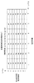
- FIG. 3 is a conceptual diagram illustrating an example of allocation of position control performance information used when the state estimating unit 104 selects the position and orientation control system provided in the first control unit 151.
- Each of ap to hp shown in FIG. 3 is an ID (Identifier) of the position control information.
- the control performance represented by each position control performance information ID is assigned so that ap is the lowest and increases as the alphabet on the left side of the ID approaches h.
- Each position control information is assigned to a combination of position responsiveness and position error.
- the position error is, for example, information indicating the maximum value of the position error resulting from the position control.
- the position responsiveness is, for example, information indicating the maximum value of the time required to reach the position after control. It is known that the position responsiveness depends on the bandwidth of the control band.
- the position control performance information is divided into six levels with respect to the position error.
- the larger the numerical value representing the level the smaller the position error can be controlled.
- the position control performance information is classified into eight levels with respect to the position responsiveness.
- the larger the numerical value representing the level the better the position responsiveness can be controlled.
- the position control performance information ID of ap having the lowest position-related control performance is assigned. Then, the position control information is allocated so that the level of the control performance becomes higher as it moves to the upper right area of FIG. When both the position error and the position responsiveness are at the highest level, the position control performance information ID of hp indicating that the position-related control performance is the highest is assigned.
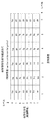
- FIG. 4 is a conceptual diagram illustrating an example of allocation of posture control performance information used by the state estimation unit 104 when selecting the position and posture control system provided in the first control unit 151.
- Each of aa to ha shown in FIG. 4 is a posture control performance information ID representing posture control information. It is assumed that the control performance indicated by each attitude control performance information ID is lowest in aa, and increases as the alphabet on the left side in each ID approaches h.
- attitude control information is assigned for a combination of attitude responsiveness and attitude error.
- the posture error is, for example, information indicating the maximum value of the posture error resulting from the posture control.
- the attitude responsiveness is, for example, information indicating the maximum value of the time required to reach the attitude after control. It is known that the attitude responsiveness depends on the bandwidth of the control band.
- the attitude control performance information is classified into six levels with respect to the attitude error.
- the larger the numerical value representing the level the smaller the attitude error can be controlled.
- the attitude control performance information is classified into eight levels with respect to attitude responsiveness.
- the attitude control performance information can control the attitude responsiveness better as the numerical value representing the level is larger.
- the attitude control performance information ID of aa indicating that the control performance regarding the attitude is the lowest level is assigned.
- Assignment of the posture control information is such that the control performance becomes higher as it goes to the upper right area in FIG.
- the attitude control performance information ID of ha indicating that the control performance regarding the attitude is the highest is assigned.
- the state estimating unit 104 shown in FIG. 2 uses the position control performance information allocation shown in FIG. 3 and the posture control performance information allocation shown in FIG. 4 to select the position and posture control system of the first control unit 151 as follows. I do.
- the state estimating unit 104 derives a required position error, position responsiveness, attitude error, and attitude responsiveness from the first information group described above.
- the state estimating unit 104 specifies the position control performance information ID by the position control performance information allocation shown in FIG. 3 from the derived position error and position responsiveness.
- the state estimation unit 104 also specifies the posture control performance information ID by the posture control performance information allocation shown in FIG. 4 from the derived posture error and posture responsiveness.
- the state estimating unit 104 stores in advance a combination of each position and orientation control system provided in the first control unit 151 and a position control performance information ID and a posture control performance information ID related to the position and orientation control system in a storage unit (not shown). It holds sixth correspondence information indicating the correspondence.
- the state estimation unit 104 refers to the sixth correspondence information, and the position control performance is higher than the specified position control performance information ID, and the posture control performance is higher than the specified posture control performance information ID. , One of the position and orientation control systems is selected. When there are a plurality of position control information units that satisfy the above performance, the state estimation unit 104 may select the one that performs the control with the lowest power consumption from among them. What performs the control with the lowest power consumption may have the lowest performance combining the position control performance and the attitude control performance.
- FIG. 5 is a conceptual diagram illustrating an example of allocating speed control performance information used when the state estimating unit 104 selects a speed angular velocity control system provided in the second control unit 152.
- Each of av to hv shown in FIG. 5 is a speed control information ID.
- the control performance represented by each speed control performance information ID is assigned so that av is the lowest and becomes higher as hv is approached in alphabetical order.
- Each speed control information is assigned for a combination of speed responsiveness and speed error.
- the speed error is, for example, information indicating a maximum value of a speed error resulting from speed control.
- the speed responsiveness is, for example, information indicating the maximum value of the time required to reach the speed after control. It is known that the speed responsiveness depends on the bandwidth of the control band.
- the speed control performance information is divided into six levels with respect to the speed error.
- the larger the numerical value representing the level the smaller the speed error can be controlled.
- the speed control performance information is classified into eight levels with respect to speed responsiveness.
- the larger the numerical value representing the level the better the speed responsiveness can be controlled.
- the speed control performance information ID of av indicating that the control performance related to the speed is the lowest level is assigned.
- FIG. 6 is a conceptual diagram illustrating an example of allocation of angular velocity performance information used when the state estimation unit 104 selects the velocity angular velocity control system provided in the second control unit 152.
- Each of ar to hr shown in FIG. 6 is an angular velocity control information ID.
- the control performance represented by each angular velocity control performance information ID is assigned such that ar is the lowest and becomes higher in the alphabetical order as hr approaches.
- Each angular velocity control information is assigned to a combination of angular velocity response and angular velocity error.
- the angular velocity error is, for example, information indicating the maximum value of the angular velocity error resulting from the angular velocity control.
- the angular velocity response is, for example, information indicating the maximum value of the time required to reach the angular velocity after control. It is known that the angular velocity response depends on the bandwidth of the control band.
- the angular velocity control performance information is divided into six levels with respect to angular velocity errors.
- Angular velocity control performance information is divided into eight levels with respect to angular velocity responsiveness.
- the level of control performance increases as the area moves to the upper right area in FIG.
- an angular velocity control performance information ID of hr indicating that the control performance relating to the angular velocity is the highest is assigned.
- the state estimating unit 104 illustrated in FIG. 2 uses the speed control performance information allocation illustrated in FIG. 5 and the angular speed control performance information allocation illustrated in FIG. 6 to select a speed angular speed control system of the second control unit 152 as follows. I do.
- the state estimating unit 104 derives the required speed error, speed responsiveness, angular speed error, and angular speed responsiveness from the first information group described above.
- the state estimating unit 104 specifies the speed control performance information ID from the derived speed error and speed responsiveness by the speed control performance information allocation shown in FIG.
- the state estimation unit 104 also specifies the angular velocity control performance information ID by the angular velocity control performance information allocation shown in FIG. 6 from the derived angular velocity error and angular velocity response.
- the state estimating unit 104 stores in the storage unit (not shown) the correspondence between the speed angular velocity control system provided in the second control unit 152 and the combination of the speed control performance information ID and the angular speed control performance information ID related to the speed angular speed control system. Is stored.
- the state estimating unit 104 refers to the seventh correspondence information, and the speed control performance is higher than the specified speed control performance information ID, and the angular speed control performance is higher than the specified angular speed control performance information ID.
- One of the velocity angular velocity control systems is selected.
- the state estimating section 104 may select a speed control information section that performs the control with the least power consumption from them.
- the one that performs the control with the least power consumption may be the one that combines the speed control performance and the angular velocity control performance with the lowest performance.
- the flying object 501 includes at least a camera, a plurality of laser rangefinders, and an anemometer as sensors of the sensor group 301.
- the sensor information acquired by these sensors is the surrounding situation information indicating the situation around the flying object 501 as described above.
- the flying object 501 is also provided with a configuration in which the working portion 451 performs a hammering test on a designated portion of a pier.
- the flying object 501 takes off from the point A, performs a hammering test on a predetermined portion of the target pier, and performs a flight landing at the point A. It is assumed that there is no obstacle between the point A and the pier group that hinders flight.
- the flying object 501 first takes off from the point A and rises to a predetermined height above the point A.
- the wind speed sensor has sent sensor information indicating that it is a breeze to the mode specifying unit 101.
- the sensor information is the above-described surrounding situation information indicating the situation of the strength of the wind around the flying object 501.
- the wind speed sensor sends the surrounding condition information indicating the strength of the wind to the mode designation unit 101.
- the mode specifying unit 101 sends the above-mentioned flight mode information S09 indicating the ascending mode in the light wind to the state estimating unit.
- the state estimating unit 104 derives the position and orientation deviation information indicating the degree of deviation between the position and orientation target information S10 and the position and orientation estimation information S07 at this time.
- ep is used as the position control performance information ID
- ea is used as the posture control performance information ID. It shall be attached.
- the state estimating unit 104 sends the control mode determination information S14 indicating that the position and orientation control is performed to the selecting unit 105.
- the state estimating unit 104 also determines, based on the position control performance information ID of ep and the posture control performance information ID of ea, the position and posture control system of the first control unit 151 that satisfies the control performance indicated by those IDs, according to the sixth correspondence. Identify by information. Then, the state estimating unit 104 sends the first selection information S12 including the ID of the specified position and orientation control system to the first control unit 151.
- the first control unit 151 specifies a position and orientation control system that performs position and orientation control based on the first selection information S12.
- the position and orientation control system generates position and orientation control information S16 based on the position and orientation estimation information S07 sent from the drive control unit and the position and orientation target information S10 included in the first selection information S12, and sends the information to the selection unit 105. Send it.
- the selection unit 105 selects the position and orientation control information S16 sent from the first control unit 151 in S14 sent from the state estimation unit 104. Then, the selection unit 105 sends the control information S15 including the position and orientation control information S16 to the drive control unit 206.
- the drive control unit 206 drives the flight enabling unit 401 according to the position and orientation control information S16 included in the control information S15.
- the flight enabling unit 401 lifts the flying object 501 to a predetermined height while keeping the attitude substantially horizontal in accordance with the position and attitude control information S16.
- the ⁇ mode designation unit 101 determines that the flying object 501 has risen to a predetermined height based on the position and orientation estimation information S07 sent from the drive control unit 206.
- the flying object 501 determines that the vehicle has reached the height based on the position and orientation estimation information S07 illustrated in FIG.
- the position and orientation estimation information S07 is movement state information indicating the movement state of the flying object 501.
- the mode specifying unit 101 switches the flight mode to the above-mentioned flight mode, ie, the horizontal flight mode in a light wind.
- the mode specifying unit 101 sends the flight mode information S09 indicating the horizontal flight mode at the time of light wind to the state estimating unit.
- the ⁇ mode designation unit 101 also derives the velocity angular velocity error information indicating the error between the velocity angular velocity target information S11 and the velocity angular velocity estimation information S08 at this time.
- the horizontal flight mode at the time of light wind is associated with the velocity angular velocity control.
- the association is performed, for example, under the circumstances that the flying object 501 is desired to fly at the maximum speed.
- the state estimating unit 104 sends the control mode determination information S14 indicating that the speed angular velocity control is performed to the selecting unit 105.
- the state estimating unit 104 also determines, based on the speed control performance information ID of av and the angular speed control performance information ID of cr, the speed angular speed control system of the second control unit 152 that satisfies the control performance indicated by those IDs according to the seventh correspondence. Specify by information. Then, the state estimating unit 104 sends the second selection information S13 including the ID of the specified speed angular velocity control system to the second control unit 152.
- the second control unit 152 specifies a speed angular velocity control system that performs speed angular velocity control based on the second selection information S13.
- the speed angular speed control system generates speed angular speed control information S17 based on the speed angular speed estimation information S08 sent from the drive control unit and the speed angular speed target information S11 included in the second selection information S13. Send it.
- the selection unit 105 selects the speed angular velocity control information S17 sent from the second control unit 152 in S14 sent from the state estimation unit 104. Then, the selection unit 105 sends control information S15 including the speed angular speed control information S17 to the drive control unit 206.
- the drive control unit 206 drives the flight enabling unit 401 according to the speed angular velocity control information S17 included in the control information S15.
- the flight enabling unit 401 causes the flying object 501 to fly according to the speed angular velocity control information S17.
- the above-described camera of the sensor group 301 captures an image of the traveling direction of the flying object 501, and sequentially obtains captured images.
- the imaging information is the above-mentioned sensor information.
- the sensor information is the surrounding situation information indicating the surrounding situation.
- the mode specifying unit 101 determines whether or not the captured image sent from the camera includes the image pattern of the pier group described above.
- the mode specifying unit 101 has an image recognition function.
- the mode designating unit 101 holds an image pattern of the pier group in a storage unit (not shown).
- the mode specifying unit 101 measures the size of the image pattern of a predetermined portion included in the pier group in the captured image.
- the mode specifying unit 101 sends the flight mode information S09 to the state estimating unit 104.
- the anemometer measures the breeze at this time.
- the mode designating unit 101 specifies the position of the flying object 501 when the size of the image pattern of the portion exceeds a predetermined value. That is, here, the mode specifying unit 101 uses the size of the image pattern of the portion as the movement status information indicating the movement status of the flying object 501.
- the state estimating unit 104 receives the transmission of the flight mode information S09 indicating the pier group passage flight mode at the time of the breeze transmitted from the mode specifying unit 101, and transmits the control mode determination information S14 for selecting the position and orientation control to the selecting unit 105.
- the reason why the flight control of the flying object 501 is switched from the velocity angular velocity control to the position / posture control is to assume that the collision of the pier group with each pier is reliably avoided.
- the state estimating unit 104 also derives the position and orientation deviation information.
- the state estimation unit 104 also specifies dp as the position control performance information ID and da as the attitude control performance information ID from the flight mode information S09 and the derived position and orientation deviation information. Then, the state estimating unit 104 specifies an ID of the position and orientation control system included in the first control unit 151 that satisfies the position control performance and the posture control performance represented by these. Then, the state estimating unit 104 sends the first selection information S12 including the ID of the specified position and orientation control unit to the first control unit 151. The first control unit 151 causes the position and orientation control system selected by the first selection information S12 to perform subsequent position and orientation control.
- the selected position and orientation control system generates position and orientation control information S16 from the position and orientation target information included in the first selection information and the position and orientation estimation information sent from the drive control unit 206, and sends the information to the selection unit 105. Send it.
- the selection unit 105 selects the position and orientation control information S16 based on the control mode determination information S14 sent from the state estimation unit 104. Then, the selection unit 105 sends the control information S15 including the position and orientation control information S16 to the drive control unit 206.
- the drive control unit 206 drives the flight enabling unit 401 based on the position and orientation control information S16 included in the control information S15, and causes the flying object 501 to contact each pier of the pier group with a margin by the position and orientation control. Make sure not to fly.
- the mode specifying unit 101 continues to determine whether or not a feature pattern representing an inspection location where a hammering inspection is to be performed appears in an image captured by the camera. When determining that the characteristic pattern has appeared in the captured image, the mode specifying unit 101 measures the size of the characteristic pattern in the captured image.
- the mode specifying unit 101 sends the flight mode information S09 indicating the approach mode in the light wind to the state estimating unit 104.
- the anemometer still observes a breeze.
- the mode specifying unit 101 specifies the position of the flying object 501 from the size of the feature pattern. That is, the mode specifying unit 101 uses the size of the feature pattern as the movement status information. Then, the mode specifying unit 101 specifies the flight mode from the surrounding situation information of the breeze and the moving situation information that the size of the feature pattern is a predetermined value.
- the state estimation unit 104 sends the control mode determination information S14 representing the position and orientation control to the selection unit 105.
- the position and orientation control is associated in advance with the approach mode at the time of light wind.
- the state estimating unit 104 derives the position and orientation error information.
- the state estimating unit 104 derives a position control performance information ID and a posture control performance information ID from the fourth correspondence information. It is assumed that the position control performance information ID at that time is hp shown in FIG. 3 and the attitude control performance information ID is ha.
- the state estimating unit 104 determines a position / orientation control system in which the position control performance is equal to or greater than the position control performance information hp and the attitude control information is equal to or greater than the attitude control performance information ha by using the sixth correspondence information. Identify. Then, the state estimating unit 104 sends the first selection information S12 including the ID of the specified position and orientation control system to the first control unit 151.
- the selected position and orientation control system generates position and orientation control information S16 from the position and orientation target information included in the first selection information and the position and orientation estimation information sent from the drive control unit 206, and sends the information to the selection unit 105. Send it.
- the selection unit 105 selects the position and orientation control information S16 based on the control mode determination information S14 sent from the state estimation unit 104. Then, the selection unit 105 sends the control information S15 including the position and orientation control information S16 to the drive control unit 206.
- the drive control unit 206 drives the flight enabling unit 401 based on the position and orientation control information S16 included in the control information S15, and gently brings the flying object 501 into contact with the hit sound measurement target by the position and orientation control.
- the mode designation unit 101 determines that the flying object 501 has come into contact with the hitting sound measurement target based on sensor information from the second laser range finder that measures the distance to the object in front of the flying object 501.
- the mode designation unit 101 sends the flight mode information S09 indicating the measurement mode to the state estimation unit 104.
- the state estimating unit 104 selects velocity angular velocity control based on the flight mode information S09. Then, the state estimating unit 104 sends the control mode determination information S14 for selecting the speed angular velocity control to the selecting unit 105.
- the flight mode information S09 is in the measurement mode, it is predetermined to perform the velocity angular velocity control for the following reason.
- the flying object 501 may be configured such that, for example, the tip of a percussion detector is connected to a wall surface of a pier or the like like a flying robot described in the section of the problem to be solved by the invention.
- the flying object 501 drives a hammer mounted on the percussion machine at a certain frequency, and generates a sound by continuously hitting the side surface with the hammer.
- the flying object 501 performs a hammering test in a predetermined range of the inspection target by moving the tip at a predetermined speed. Therefore, it is important that the speed at which the tip moves is as set.
- the speed at which the tip moves depends on the speed and angular speed of the flying object 501. Therefore, it is necessary to control the speed and angular velocity of the flying object 501.
- the state estimating unit 104 also calculates, based on the flight mode information S09 and the degree of deviation between the speed angular velocity target information S11 and the speed angular velocity estimation information S08, a speed control performance information ID previously associated with a combination thereof.
- the angular velocity control performance information ID is specified. It is assumed that the speed control performance information ID at that time is hv shown in FIG. 5 and the angular speed control performance information ID is hr shown in FIG.
- the state estimating unit 104 specifies the speed / angular speed control system in which the speed control performance is represented by the speed control performance information hv and the angular speed control information is the angular speed control performance information hr. Then, the state estimating unit 104 sends the second selection information S13 including the ID of the specified speed angular velocity control system to the second control unit 152.
- the selected velocity angular velocity control system generates velocity angular velocity control information S17 from velocity angular velocity target information S11 included in the second selection information S13 and velocity angular velocity estimation information S08 sent from the drive control unit 206. To the unit 105.
- the selection unit 105 selects the speed angular velocity control information S17 based on the control mode determination information S14 sent from the state estimation unit 104. Then, the selection unit 105 sends control information S15 including the speed angular speed control information S17 to the drive control unit 206.
- the drive control unit 206 drives the flight enabling unit 401 based on the speed angular velocity control information S17 included in the control information S15, and causes the hitting unit of the flying object 501 to hit the hitting sound measurement target by speed angular velocity control. . Then, the work control unit 256 and the work unit 451 measure the hammering sound of the hammering sound measurement target.
- the flying object 501 makes a return flight to the point A.
- the flying object 501 flies between the piers of the pier group.
- the mode designating unit 101 switches the flight mode information S09 sent to the state estimating unit 104 from the initial pier group flight flight mode at low winds to the pier passage mode at high winds.
- the mode specifying unit 101 switches the flight mode based on the surrounding condition information such as the wind speed.
- the state estimating unit 104 raises the position control capability and the posture control capability of the position / posture control system selected by the first control unit 151 while maintaining the position / posture control in S14.
- the raising is performed in order to increase the response speed for bringing the position and orientation of the flying object 501 closer to the position and orientation target when the flying object 501 is hit by a strong wind.
- the mode specifying unit 101 When determining that the estimated position of the flying object 501 is separated from the pier group by a predetermined distance, the mode specifying unit 101 switches the flight mode to the horizontal flight mode.
- the mode specifying unit 101 determines that the vehicle is separated from the pier group by a predetermined distance based on the position and orientation estimation information S07 that is the movement status information.
- the velocity angular velocity control system of the second control unit 152 selected in the same manner as described above performs velocity angular velocity control on the drive control unit 206.
- the mode specifying unit 101 determines that the estimated position of the flying object 501 has approached the point A, it switches the flight mode to the landing mode. At this time, the mode specifying unit 101 determines that the vehicle has approached the point A based on the position and orientation estimation information S07 that is the movement status information.
- the flying object of the present embodiment controls the position and attitude of the flying object (position / posture control) based on the sensor information indicating the situation around the flying object and the moving situation information indicating the moving situation, or controls the speed and angular velocity. Select whether to perform control (speed angular velocity control).
- the flying object can perform flight control (positioning control and movement control) more suitable for the surrounding situation and the movement situation.
- the performance (accuracy) of position and orientation control is selected based on the sensor information and the movement status information.
- the flying object selects performance (accuracy) of velocity angular velocity control based on the sensor information and the movement status information.
- the flying object can perform flight control (positioning control and movement control) more suitable for the surrounding situation and the movement situation.
- each sensor of the sensor group is mounted on the flying object, but some sensors may be installed outside the flying object to measure the state of the flying object. good.
- the movement control unit has a function of receiving information transmitted wirelessly from a sensor installed outside.
- the movement control unit is assumed to be provided in the flying object, but a part and all of the movement control unit may be installed outside the flying object. In that case, each of the external components can communicate with the corresponding components installed on the flying object by radio or the like.
- the moving object is a flying object
- the moving object according to the embodiment is not limited to an aerial moving device such as a flying object.
- the moving object may be a ground moving device, a ground moving device, an object surface moving device, an object internal moving device, a liquid moving device, a liquid moving device, a space moving device, or the like.
- FIG. 7 is a block diagram illustrating a configuration of a selection device 201x which is a minimum configuration of the selection device according to the embodiment.
- the selection device 201x includes a movement mode designation unit 101x and a selection unit 105x.
- the movement mode designating unit 101x designates a movement mode related to the movement from the surrounding situation information representing the situation around the moving body to be moved and the movement situation information representing the movement situation of the moving body.
- the selecting unit 105x performs a first control mode for performing a first control, which is a control of a position and a posture of the moving body, and a second control for performing a second control, which is a control of a speed and an angular velocity of the moving body, according to the movement mode.
- a control mode selection which is one of the modes, is performed.
- the selection device 201x determines the control mode related to the movement, the first control mode for controlling the position and attitude of the moving body, and the speed and angular velocity of the moving body according to the situation around the moving body and the moving situation.
- the mode is switched between the control mode and the second control mode.
- the selecting unit 105x achieves the effects described in the section of “Effects of the Invention” with the above configuration.
- the selection device 201x illustrated in FIG. 7 is, for example, a combination of the determination unit 150 and the selection unit 105 illustrated in FIG.
- the movement mode specifying unit 101x is, for example, the mode specifying unit 101 illustrated in FIG.
- the selection unit 105x is, for example, a combination of the state estimation unit 104 and the selection unit 105 illustrated in FIG.
- the moving object is, for example, the flying object 501 shown in FIG.
- the movement status information is, for example, the above-described position and orientation estimation information or image information representing the position of the moving body in the above-described sensor information.
- the movement mode is, for example, the flight mode described above.
- the first control mode is, for example, the above-described position and orientation control mode.
- the second control mode is, for example, the above-described angular velocity control information.
- a selection unit for performing a control mode selection as a selection of A selection device comprising: (Appendix 2) The selection device according to claim 1, wherein the surrounding situation information is transmitted from a sensor that acquires the surrounding situation. (Appendix 3) The selection device according to Supplementary Note 1 or 2, wherein the surrounding situation information includes information indicating a wind speed or a direction related to a wind hitting the moving body. (Appendix 4) The selection device according to any one of Supplementary Notes 1 to 3, wherein the surrounding situation information includes image information captured by the moving body. (Appendix 5) The selection device according to any one of Supplementary Notes 1 to 4, wherein the surrounding situation information includes information indicating a distance between the moving body and an object existing around the moving body.
- the moving mode designating unit may include, as the moving state information, information indicating a size of a predetermined object in an image captured by an imaging device included in the moving body, wherein The selection device described in item (1).
- the selection device described in item (1).
- the selection device according to any one of Supplementary Notes 1 to 9, wherein the selection unit performs a first selection that is a selection of the performance of the first control.
- Supplementary note 10 wherein the performance of the first control is based on a combination of an error and a response time related to position control of the moving body, and a combination of an error and a response time related to attitude control of the moving body. Selection equipment.
- (Appendix 23) The selection device according to any one of supplementary notes 1 to 22, and A first control unit that performs the first control, And a second control unit that performs the second control.
- (Appendix 24) A control device according to attachment 23, A movement enabling unit that is controlled by the control device and enables the movement, A moving device that is the moving object, comprising: (Appendix 25) The mobile device according to attachment 24, further comprising a sensor for acquiring the surrounding situation information. (Supplementary Note 26) The mobile device according to attachment 24 or 25, wherein the mobile device is a multicopter or a drone.
- a working device comprising: (Appendix 28) The working device according to attachment 27, wherein the work is an inspection of an object. (Appendix 29) The working device according to attachment 28, wherein the inspection is a tapping inspection to check a sound state by hitting the object.
- a process of selecting a control mode which is a selection of Recording medium for recording a selection program for causing a computer to execute the program.
Landscapes
- Engineering & Computer Science (AREA)
- Remote Sensing (AREA)
- Aviation & Aerospace Engineering (AREA)
- Physics & Mathematics (AREA)
- General Physics & Mathematics (AREA)
- Automation & Control Theory (AREA)
- Radar, Positioning & Navigation (AREA)
- Multimedia (AREA)
- Microelectronics & Electronic Packaging (AREA)
- Mechanical Engineering (AREA)
- Theoretical Computer Science (AREA)
- Control Of Position, Course, Altitude, Or Attitude Of Moving Bodies (AREA)
- Manipulator (AREA)
Abstract
Priority Applications (3)
| Application Number | Priority Date | Filing Date | Title |
|---|---|---|---|
| CN201980049951.9A CN112470091A (zh) | 2018-08-22 | 2019-08-20 | 选择设备、选择方法和选择程序 |
| JP2020538386A JP7036220B2 (ja) | 2018-08-22 | 2019-08-20 | 選定装置、選定方法及び選定プログラム |
| US17/269,126 US20210325908A1 (en) | 2018-08-22 | 2019-08-20 | Selection device, selection method, and selection program |
Applications Claiming Priority (2)
| Application Number | Priority Date | Filing Date | Title |
|---|---|---|---|
| JP2018155678 | 2018-08-22 | ||
| JP2018-155678 | 2018-08-22 |
Publications (1)
| Publication Number | Publication Date |
|---|---|
| WO2020040105A1 true WO2020040105A1 (fr) | 2020-02-27 |
Family
ID=69593147
Family Applications (1)
| Application Number | Title | Priority Date | Filing Date |
|---|---|---|---|
| PCT/JP2019/032339 Ceased WO2020040105A1 (fr) | 2018-08-22 | 2019-08-20 | Dispositif de sélection, procédé de sélection, et programme de sélection |
Country Status (4)
| Country | Link |
|---|---|
| US (1) | US20210325908A1 (fr) |
| JP (1) | JP7036220B2 (fr) |
| CN (1) | CN112470091A (fr) |
| WO (1) | WO2020040105A1 (fr) |
Citations (7)
| Publication number | Priority date | Publication date | Assignee | Title |
|---|---|---|---|---|
| JPS59169610U (ja) * | 1983-04-22 | 1984-11-13 | 三菱電機株式会社 | 人工衛星の姿勢制御装置 |
| JPS6156669B2 (fr) | 1980-11-19 | 1986-12-03 | Intaanashonaru Bijinesu Mashiinzu Corp | |
| JPS6388603A (ja) * | 1986-10-02 | 1988-04-19 | Agency Of Ind Science & Technol | 海中ロボツトの走行制御方法 |
| JP2017217942A (ja) | 2016-06-03 | 2017-12-14 | 株式会社衛星ネットワーク | 無人機システム、無人機、係留装置 |
| CN107608368A (zh) * | 2017-09-26 | 2018-01-19 | 南京航空航天大学 | 一种无人机在极端初始状态的快速平衡控制方法 |
| CN108227719A (zh) * | 2018-01-31 | 2018-06-29 | 浙江国自机器人技术有限公司 | 一种移动机器人到位精度控制方法、系统、介质及设备 |
| JP2018155678A (ja) | 2017-03-21 | 2018-10-04 | 三菱電機株式会社 | レーダ装置 |
Family Cites Families (17)
| Publication number | Priority date | Publication date | Assignee | Title |
|---|---|---|---|---|
| FR2902081B1 (fr) * | 2006-06-12 | 2008-07-11 | Airbus France Sas | Procede et dispositif d'assistance a l'atterissage pour aeronef |
| US9547306B2 (en) * | 2014-09-30 | 2017-01-17 | Speak Loud SPA | State and context dependent voice based interface for an unmanned vehicle or robot |
| JP6852672B2 (ja) * | 2015-08-25 | 2021-03-31 | 日本電気株式会社 | 飛行体制御装置、飛行体制御方法、及びプログラム |
| US20170160751A1 (en) * | 2015-12-04 | 2017-06-08 | Pilot Ai Labs, Inc. | System and method for controlling drone movement for object tracking using estimated relative distances and drone sensor inputs |
| TWI682876B (zh) | 2016-05-27 | 2020-01-21 | 日商日本電氣股份有限公司 | 檢查系統、管制裝置以及管制方法 |
| CN205844898U (zh) * | 2016-06-28 | 2016-12-28 | 江苏中科院智能科学技术应用研究院 | 一种适用小型无人机的飞控设备 |
| CN106444800A (zh) * | 2016-08-01 | 2017-02-22 | 中国人民武装警察部队总医院 | 多旋翼无人机飞行用外置式安全控制装置、方法及系统 |
| JP2018055463A (ja) * | 2016-09-29 | 2018-04-05 | セコム株式会社 | 飛行ロボット制御システムおよび飛行ロボット |
| CN106527479B (zh) * | 2016-11-29 | 2017-12-12 | 广州极飞科技有限公司 | 一种无人机的控制方法及装置 |
| WO2018131153A1 (fr) * | 2017-01-16 | 2018-07-19 | 株式会社日立製作所 | Dispositif et procédé de commande de corps mobile |
| JP2018116443A (ja) | 2017-01-18 | 2018-07-26 | 住友重機械工業株式会社 | 検査システム |
| WO2018135332A1 (fr) | 2017-01-18 | 2018-07-26 | ソニー株式会社 | Dispositif de commande d'orientation, objet volant, procédé de commande d'orientation et programme |
| US10168704B2 (en) * | 2017-06-05 | 2019-01-01 | Hanzhou Zero Zero Technology Co., Ltd. | System and method for providing easy-to-use release and auto-positioning for drone applications |
| WO2019016930A1 (fr) * | 2017-07-21 | 2019-01-24 | 日本電気株式会社 | Dispositif de traitement de données, dispositif de commande d'entraînement, corps mobile, procédé de traitement de données, procédé de commande d'entraînement et support de stockage |
| EP3668788B1 (fr) * | 2017-08-15 | 2023-10-18 | Saronikos Trading and Services, Unipessoal Lda | Aéronef multirotor amélioré et dispositif d'interface |
| CN207725609U (zh) * | 2017-10-24 | 2018-08-14 | 深圳市瑞杰创新科技有限公司 | 基于速度传感器技术的无人机 |
| KR101880940B1 (ko) * | 2017-10-31 | 2018-07-23 | 드로젠(주) | 자세 제어 방법 및 그를 적용한 드론 |
-
2019
- 2019-08-20 WO PCT/JP2019/032339 patent/WO2020040105A1/fr not_active Ceased
- 2019-08-20 CN CN201980049951.9A patent/CN112470091A/zh active Pending
- 2019-08-20 JP JP2020538386A patent/JP7036220B2/ja active Active
- 2019-08-20 US US17/269,126 patent/US20210325908A1/en not_active Abandoned
Patent Citations (7)
| Publication number | Priority date | Publication date | Assignee | Title |
|---|---|---|---|---|
| JPS6156669B2 (fr) | 1980-11-19 | 1986-12-03 | Intaanashonaru Bijinesu Mashiinzu Corp | |
| JPS59169610U (ja) * | 1983-04-22 | 1984-11-13 | 三菱電機株式会社 | 人工衛星の姿勢制御装置 |
| JPS6388603A (ja) * | 1986-10-02 | 1988-04-19 | Agency Of Ind Science & Technol | 海中ロボツトの走行制御方法 |
| JP2017217942A (ja) | 2016-06-03 | 2017-12-14 | 株式会社衛星ネットワーク | 無人機システム、無人機、係留装置 |
| JP2018155678A (ja) | 2017-03-21 | 2018-10-04 | 三菱電機株式会社 | レーダ装置 |
| CN107608368A (zh) * | 2017-09-26 | 2018-01-19 | 南京航空航天大学 | 一种无人机在极端初始状态的快速平衡控制方法 |
| CN108227719A (zh) * | 2018-01-31 | 2018-06-29 | 浙江国自机器人技术有限公司 | 一种移动机器人到位精度控制方法、系统、介质及设备 |
Non-Patent Citations (3)
| Title |
|---|
| MICHITARO SHOZAWA ET AL.: "Development of the Safe Inspection System for Infrastructure Using Flying Robot", PROCEEDINGS OF THE 55TH AIRCRAFT SYMPOSIUM |
| TOSHIAKI YAMASHITA ET AL.: "Inspection System for Infrastructure Using Flying Robot", PROCEEDINGS OF THE 53RD AIRCRAFT SYMPOSIUM |
| TOSHIAKI YAMASHITA ET AL.: "Performance Evaluation of Inspection System for Infrastructure Using Flying Robot", PROCEEDINGS OF THE 54TH AIRCRAFT SYMPOSIUM |
Also Published As
| Publication number | Publication date |
|---|---|
| CN112470091A (zh) | 2021-03-09 |
| US20210325908A1 (en) | 2021-10-21 |
| JPWO2020040105A1 (ja) | 2021-08-10 |
| JP7036220B2 (ja) | 2022-03-15 |
Similar Documents
| Publication | Publication Date | Title |
|---|---|---|
| JP6239619B2 (ja) | 位置決め及び相互動作用紐集合体を備えたフライングカメラ | |
| JP6179502B2 (ja) | マルチコプタを用いた3次元形状計測方法および装置 | |
| US20180003161A1 (en) | Unmanned aerial vehicle wind turbine inspection systems and methods | |
| US20230267843A1 (en) | System for repositioning UAV swarm | |
| EP3908520B1 (fr) | Détection d'une défaillance imminente d'un moteur à l'aide de données audio | |
| WO2018110088A1 (fr) | Véhicule aérien sans pilote et procédé de commande de véhicule aérien sans pilote | |
| CN111465556B (zh) | 信息处理系统、信息处理方法及电脑可读存储媒体 | |
| WO2017217470A1 (fr) | Système d'inspection, dispositif de robot mobile et procédé d'inspection | |
| JP2019537140A (ja) | ビークル衝突回避 | |
| Ghazali et al. | Determining position of target subjects in Maritime Search and Rescue (MSAR) operations using rotary wing Unmanned Aerial Vehicles (UAVs) | |
| KR20210115313A (ko) | 드론 관제 방법 및 장치 | |
| US20210147075A1 (en) | Landing apparatus, landing control method, and landing control program | |
| JP2020045049A (ja) | 航空機の着陸支援装置、航空機の着陸支援方法及び航空機の着陸支援プログラム | |
| US20210116248A1 (en) | Inspection management device, inspection management method, and recording medium to store program | |
| WO2020189492A1 (fr) | Dispositif de traitement d'informations et procédé de traitement d'informations | |
| JP2020013465A (ja) | マルチコプターを対象とする壁面トレース型飛行制御システム | |
| KR102448233B1 (ko) | 정밀 착륙을 위한 드론 제어 방법 | |
| WO2020166348A1 (fr) | Corps mobile, procédé de communication et programme | |
| JP2018077754A (ja) | 自律移動装置、プログラムおよび制御方法 | |
| JP7679097B2 (ja) | 作業計画生成システム | |
| US12307762B2 (en) | Information processing device, method, computer program, and communication system | |
| JP7036220B2 (ja) | 選定装置、選定方法及び選定プログラム | |
| CN104309795A (zh) | 低空检测浮空平台 | |
| CN211943738U (zh) | 无人机基站、装置及无人机系统 | |
| KR20230030149A (ko) | 군집 드론을 이용한 원격 인스펙션 시스템 |
Legal Events
| Date | Code | Title | Description |
|---|---|---|---|
| 121 | Ep: the epo has been informed by wipo that ep was designated in this application |
Ref document number: 19852390 Country of ref document: EP Kind code of ref document: A1 |
|
| ENP | Entry into the national phase |
Ref document number: 2020538386 Country of ref document: JP Kind code of ref document: A |
|
| NENP | Non-entry into the national phase |
Ref country code: DE |
|
| ENP | Entry into the national phase |
Ref document number: 2019852390 Country of ref document: EP Effective date: 20210322 |
|
| 122 | Ep: pct application non-entry in european phase |
Ref document number: 19852390 Country of ref document: EP Kind code of ref document: A1 |