WO2020040118A1 - Incubateur de cellules - Google Patents
Incubateur de cellules Download PDFInfo
- Publication number
- WO2020040118A1 WO2020040118A1 PCT/JP2019/032384 JP2019032384W WO2020040118A1 WO 2020040118 A1 WO2020040118 A1 WO 2020040118A1 JP 2019032384 W JP2019032384 W JP 2019032384W WO 2020040118 A1 WO2020040118 A1 WO 2020040118A1
- Authority
- WO
- WIPO (PCT)
- Prior art keywords
- culture
- medium
- tank
- flow path
- cell
- Prior art date
- Legal status (The legal status is an assumption and is not a legal conclusion. Google has not performed a legal analysis and makes no representation as to the accuracy of the status listed.)
- Ceased
Links
Images


















Classifications
-
- C—CHEMISTRY; METALLURGY
- C12—BIOCHEMISTRY; BEER; SPIRITS; WINE; VINEGAR; MICROBIOLOGY; ENZYMOLOGY; MUTATION OR GENETIC ENGINEERING
- C12M—APPARATUS FOR ENZYMOLOGY OR MICROBIOLOGY; APPARATUS FOR CULTURING MICROORGANISMS FOR PRODUCING BIOMASS, FOR GROWING CELLS OR FOR OBTAINING FERMENTATION OR METABOLIC PRODUCTS, i.e. BIOREACTORS OR FERMENTERS
- C12M25/00—Means for supporting, enclosing or fixing the microorganisms, e.g. immunocoatings
- C12M25/02—Membranes; Filters
-
- C—CHEMISTRY; METALLURGY
- C12—BIOCHEMISTRY; BEER; SPIRITS; WINE; VINEGAR; MICROBIOLOGY; ENZYMOLOGY; MUTATION OR GENETIC ENGINEERING
- C12M—APPARATUS FOR ENZYMOLOGY OR MICROBIOLOGY; APPARATUS FOR CULTURING MICROORGANISMS FOR PRODUCING BIOMASS, FOR GROWING CELLS OR FOR OBTAINING FERMENTATION OR METABOLIC PRODUCTS, i.e. BIOREACTORS OR FERMENTERS
- C12M23/00—Constructional details, e.g. recesses, hinges
- C12M23/02—Form or structure of the vessel
- C12M23/12—Well or multiwell plates
-
- C—CHEMISTRY; METALLURGY
- C12—BIOCHEMISTRY; BEER; SPIRITS; WINE; VINEGAR; MICROBIOLOGY; ENZYMOLOGY; MUTATION OR GENETIC ENGINEERING
- C12M—APPARATUS FOR ENZYMOLOGY OR MICROBIOLOGY; APPARATUS FOR CULTURING MICROORGANISMS FOR PRODUCING BIOMASS, FOR GROWING CELLS OR FOR OBTAINING FERMENTATION OR METABOLIC PRODUCTS, i.e. BIOREACTORS OR FERMENTERS
- C12M23/00—Constructional details, e.g. recesses, hinges
- C12M23/34—Internal compartments or partitions
-
- C—CHEMISTRY; METALLURGY
- C12—BIOCHEMISTRY; BEER; SPIRITS; WINE; VINEGAR; MICROBIOLOGY; ENZYMOLOGY; MUTATION OR GENETIC ENGINEERING
- C12M—APPARATUS FOR ENZYMOLOGY OR MICROBIOLOGY; APPARATUS FOR CULTURING MICROORGANISMS FOR PRODUCING BIOMASS, FOR GROWING CELLS OR FOR OBTAINING FERMENTATION OR METABOLIC PRODUCTS, i.e. BIOREACTORS OR FERMENTERS
- C12M29/00—Means for introduction, extraction or recirculation of materials, e.g. pumps
- C12M29/04—Filters; Permeable or porous membranes or plates, e.g. dialysis
-
- C—CHEMISTRY; METALLURGY
- C12—BIOCHEMISTRY; BEER; SPIRITS; WINE; VINEGAR; MICROBIOLOGY; ENZYMOLOGY; MUTATION OR GENETIC ENGINEERING
- C12M—APPARATUS FOR ENZYMOLOGY OR MICROBIOLOGY; APPARATUS FOR CULTURING MICROORGANISMS FOR PRODUCING BIOMASS, FOR GROWING CELLS OR FOR OBTAINING FERMENTATION OR METABOLIC PRODUCTS, i.e. BIOREACTORS OR FERMENTERS
- C12M37/00—Means for sterilizing, maintaining sterile conditions or avoiding chemical or biological contamination
- C12M37/04—Seals
-
- C—CHEMISTRY; METALLURGY
- C12—BIOCHEMISTRY; BEER; SPIRITS; WINE; VINEGAR; MICROBIOLOGY; ENZYMOLOGY; MUTATION OR GENETIC ENGINEERING
- C12M—APPARATUS FOR ENZYMOLOGY OR MICROBIOLOGY; APPARATUS FOR CULTURING MICROORGANISMS FOR PRODUCING BIOMASS, FOR GROWING CELLS OR FOR OBTAINING FERMENTATION OR METABOLIC PRODUCTS, i.e. BIOREACTORS OR FERMENTERS
- C12M41/00—Means for regulation, monitoring, measurement or control, e.g. flow regulation
- C12M41/12—Means for regulation, monitoring, measurement or control, e.g. flow regulation of temperature
- C12M41/14—Incubators; Climatic chambers
-
- C—CHEMISTRY; METALLURGY
- C12—BIOCHEMISTRY; BEER; SPIRITS; WINE; VINEGAR; MICROBIOLOGY; ENZYMOLOGY; MUTATION OR GENETIC ENGINEERING
- C12M—APPARATUS FOR ENZYMOLOGY OR MICROBIOLOGY; APPARATUS FOR CULTURING MICROORGANISMS FOR PRODUCING BIOMASS, FOR GROWING CELLS OR FOR OBTAINING FERMENTATION OR METABOLIC PRODUCTS, i.e. BIOREACTORS OR FERMENTERS
- C12M41/00—Means for regulation, monitoring, measurement or control, e.g. flow regulation
- C12M41/48—Automatic or computerized control
Definitions
- the present invention relates to cell technology, and relates to a cell incubator.
- Embryonic stem cells are stem cells established from early human or mouse embryos. ES cells have pluripotency that can be differentiated into all cells present in a living body. Currently, human ES cells are available for cell transplantation therapy for many diseases, such as Parkinson's disease, juvenile diabetes, and leukemia. However, there are obstacles to transplantation of ES cells. In particular, transplantation of ES cells can cause an immune rejection similar to the rejection that occurs following an unsuccessful organ transplant. Also, there are many criticisms and oppositions from the ethical point of view regarding the use of ES cells established by destroying human embryos.
- iPS Cells induced pluripotent stem cells
- iPS Cells induced pluripotent stem cells
- An object of the present invention is to provide a cell incubator capable of efficiently culturing cells.
- a culture component permeable member through which a culture component is permeable, a culture tank that covers a surface of the culture component permeable member, holds a cell-containing medium, and cultures cells
- a cell incubator comprising: a medium holding tank for holding a medium, which covers the other surface of the permeable member.
- the culture component permeable member may be a semi-permeable membrane.
- the above-described cell incubator further includes a culture-side plate and a culture-side plate each having an opening, sandwiching the culture-component-permeable member, and the cell-containing medium in the culture tank is provided with a culture component through the opening of the culture-side plate.
- the culture medium in the culture medium holding tank may be in contact with the culture component transmission member through the opening of the culture medium side plate.
- the culture side plate may be dark.
- the culture tank and the medium holding tank may be detachable.
- the surface of the culture side plate may be non-cell-adhesive.
- the surface of the culture side plate may be non-protein-adhesive.
- the surface of the culture side plate may be cell-adhesive.
- the surface of the culture component permeable member may be non-cell-adhesive.
- the surface of the culture component permeable member may be non-protein-adhesive.
- the surface of the culture component permeable member may be cell-adhesive.
- the culture component permeable member may be cell-adhesive.
- the culture component permeable member may be non-cell-adhesive.
- the cells, microorganisms, viruses, and dust outside the culture tank and the medium holding tank do not enter the culture tank and the medium holding tank. Good.
- the substances in the culture tank and the medium holding tank do not have to flow out of the culture tank and the medium holding tank in a state where the culture tank and the medium holding tank are sealed.
- gas exchange does not have to occur inside and outside the culture tank and the medium holding tank in a state where the culture tank and the medium holding tank are sealed.
- At least one of carbon dioxide gas, nitrogen gas, and oxygen gas may not be supplied into the culture tank and the medium holding tank with the culture tank and the medium holding tank being sealed.
- the pH of the culture medium in the culture tank and the culture medium holding tank may be maintained within a predetermined range.
- the culture tank may be embedded in a gas impermeable substance.
- the medium holding tank may be embedded in a gas impermeable substance.
- a packing disposed between the culture component permeable member and the culture tank may be further provided.
- the packing may be disposed between the outer periphery of the culture component permeable member and the culture tank.
- the outer diameter of the packing may be larger than the outer diameter of the culture component permeable member.
- the above-described cell incubator may further include a packing disposed between the culture component permeable member and the culture medium holding tank.
- the packing may be arranged between the outer periphery of the culture component permeable member and the culture medium holding tank.
- the outer diameter of the packing may be larger than the outer diameter of the culture component permeable member.
- the inside of the culture tank may be non-adhesive.
- the inside of the culture tank may be non-protein-adhesive.
- the inside of the culture tank may be cell-adhesive.
- a sealable culture tank for culturing cells for culturing cells, a supply port for supplying a fluid into the culture tank, and a discharge port for discharging the fluid from the culture tank are provided in the culture tank, and the supply port and the discharge port are sealable.
- a supply device for supplying a fluid to the supply port may be detachable.
- the supply device may be connected to the supply port via a supply needleless connector.
- a discharger for discharging a fluid to the discharge port may be detachable.
- the discharger may be connected to the discharge port via a discharge needleless connector.
- a supply device for supplying a fluid to the supply port is detachable
- a discharge device for discharging the fluid to the discharge port is detachable
- the fluid is supplied from the supply device into the culture tank.
- the fluid in the culture vessel may move into the ejector.
- the air in the culture tank may move into the discharger.
- the culture medium in the culture tank may move into the discharger.
- the medium may contain cells.
- a window may be provided.
- a window may be provided with a transparent heater.
- the above-described culture tank may include a temperature control unit for controlling the temperature inside the culture tank.
- the above-mentioned culture tank may be provided with a thermometer for measuring the temperature inside the culture tank.
- the substance in the culture tank does not have to flow out of the culture tank in a state where the culture tank is sealed.
- gas exchange may not be performed inside and outside the culture tank in a state where the culture tank is sealed.
- At least one of carbon dioxide gas, nitrogen gas, and oxygen gas may not be supplied into the culture tank in a state where the culture tank is sealed.
- the pH of the culture medium in the culture tank may be kept in a predetermined range.
- the culture tank may be embedded in a gas impermeable substance.
- the inclination of the culture tank may be adjustable.
- stem cells may be expanded and cultured.
- the stem cells may be iPS cells, ES cells, or somatic stem cells.
- cells into which the inducer has been introduced may be cultured and induced into stem cells.
- an inducer may be added to a medium in the culture tank, and the inducer may be introduced into cells cultured in the culture tank.
- cells into which the inducer has been introduced may be induced into stem cells.
- the stem cells may be iPS cells.
- the cells may be blood cells.
- cells into which the inducer has been introduced may be cultured in the culture tank and induced into another type of cells.
- an inducer may be added to the medium in the culture tank, the inducer may be introduced into cells cultured in the culture tank, and the cells may be induced to different kinds of cells.
- the inducing factor may be RNA.
- an inducing factor may be contained in Sendai virus.
- an inducing factor may be contained in the plasmid.
- ⁇ Cells may be cultured in the above-mentioned culture tank.
- the cells may be at least one selected from blood cells, neural cells, cardiomyocytes, epithelial cells, mesenchymal cells, and hepatocytes.
- cells may be subjected to suspension culture in the culture tank.
- cells may be adhered and cultured in the culture tank.
- cells may be cultured in a gel medium in the culture tank.
- the inside may be non-cell-adhesive.
- the inside may be non-protein-adhesive.
- the inside may be cell-adhesive.
- a culture apparatus including the culture tank described above, and an imaging device configured to photograph at least one of a culture medium and cells in the culture tank.
- the photographing device may photograph cells through a telecentric lens.
- the culture device described above may further include an image processing unit that applies a high-pass filter to an image obtained by the imaging device.
- the image processing unit may apply a watershed algorithm to the image to which the high-pass filter has been applied, and extract cells or cell clusters in the image.
- the image processing unit may apply the Distance Transform method to the image before applying the watershed algorithm to the image.
- the image processing unit may calculate the size of the extracted cell or cell soul.
- the image processing unit may calculate the number of extracted cells or cell souls.
- the culture device further includes a relationship storage device that stores a relationship between the turbidity of the culture medium and the density of cells or cell souls in the culture medium, based on the image obtained by the imaging device, the culture medium in the culture tank.
- the image processing unit may further include an image processing unit that calculates a value of turbidity and calculates a value of a density of a photographed cell or cell soul based on the calculated turbidity value and the relationship.
- the culture device further includes a relationship storage device that stores a relationship between the color of the culture medium and the pH of the culture medium, and calculates the value of the color of the culture medium in the culture tank in the image obtained by the imaging device.
- the image processing unit may further include an image processing unit that calculates a pH value of the photographed culture medium based on the obtained color value and the relationship.
- a sealable culture medium holding tank for holding a culture medium, a sealable culture medium holding tank, an inlet for supplying a fluid into the culture medium holding tank, and a fluid in the culture medium holding tank And a discharge port for discharging the medium is provided in the culture medium holding tank, and the culture medium holding tank is provided, in which the introduction port and the discharge port are sealable.
- a supply device for supplying a fluid to the inlet may be detachable.
- the supply device may be connected to the introduction port via a supply needleless connector.
- a discharger for discharging a fluid to the discharge port may be detachable.
- the discharger may be connected to the discharge port via a discharge needleless connector.
- a supply device for supplying a fluid to the introduction port is detachable, and a discharger for discharging the fluid to the discharge port is detachable, and the supply device is provided in the medium holding tank.
- the fluid in the medium holding tank may move into the ejector.
- the air in the medium holding tank may move into the discharger.
- the medium in the medium holding tank may move into the discharger.
- the medium holding tank may include a temperature control unit for adjusting the temperature inside the medium holding tank.
- the medium holding tank may be provided with a thermometer for measuring the temperature inside the medium holding tank.
- the substance in the medium holding tank may not flow out of the medium holding tank in a state where the medium holding tank is sealed.
- gas exchange may not be performed inside and outside the medium holding tank in a state where the medium holding tank is sealed.
- At least one of carbon dioxide gas, nitrogen gas, and oxygen gas may not be supplied into the medium holding tank in a state where the medium holding tank is sealed.
- the pH of the medium in the medium holding tank may be kept in a predetermined range.
- the medium holding tank may be embedded in a gas impermeable substance.
- a current plate may be provided in the medium holding tank.
- one or more outlets for supplying the medium into the medium holding tank may be provided with one or more outlets communicating with the inlet.
- a discharge block provided with one or more discharge ports for supplying a culture medium in the medium holding tank, the discharge ports being provided with one or more discharge ports capable of communicating with an introduction port. May be insertable.
- an opening may be provided for taking out the air in the medium holding tank when the medium is introduced into the medium holding tank.
- a medium passage may be connected to the inlet and the outlet of the medium holding tank.
- the medium may be circulated between the medium holding tank and the medium flow path.
- the inside of the medium holding tank may be sealed by connecting the medium holding tank to the medium flow path.
- the medium holding tank may be connected to a culture tank for culturing cells.
- the inside of the medium holding tank may be sealed by connecting the medium holding tank to the culture tank.
- a sealable culture channel for supplying a fluid into the culture channel, and an outlet for discharging a fluid in the culture channel. And are provided in the culture medium flow path, and the supply port and the discharge port are sealable.
- a supply device for supplying a fluid to the supply port may be detachable.
- the supply device may be connected to the supply port via a supply needleless connector.
- a discharger for discharging a fluid to the discharge port may be detachable.
- the discharger may be connected to the discharge port via a discharge needleless connector.
- a supply device for supplying a fluid to the supply port is detachable, and a discharge device for discharging the fluid to the discharge port is detachable, and from the supply device into the medium flow path.
- the fluid in the medium flow path may move into the ejector.
- a fluid machine provided in the medium flow path for moving a fluid may be further provided.
- a supply device for supplying a fluid to the supply port is detachable
- a discharge device for discharging the fluid to the discharge port is detachable, and when the fluid machine is driven, the supply is performed.
- a fluid may be supplied from the vessel to the medium flow path, and the fluid in the medium flow path may move into the discharger.
- the air in the culture medium flow path may move into the discharger.
- the culture medium in the culture medium flow path may move into the ejector.
- the medium flow path may include a temperature control unit for adjusting the temperature inside the medium flow path.
- the above-described medium flow path may include a thermometer for measuring the temperature inside the medium flow path.
- outside air may not enter the medium flow path in a state where the medium flow path is sealed.
- cells, microorganisms, viruses, and dust outside the medium flow path may not enter the medium flow path in a state where the medium flow path is sealed.
- the substance in the medium flow path may not flow out of the medium flow path in a state where the medium flow path is sealed.
- gas exchange may not be performed inside and outside the medium flow path in a state where the medium flow path is sealed.
- At least one of carbon dioxide gas, nitrogen gas, and oxygen gas may not be supplied into the medium flow path in a state where the medium flow path is sealed.
- the pH of the medium in the medium flow path may be kept within a predetermined range.
- the above-mentioned medium flow path may be blocked from the outside air by a medium flow path outside air blocking member.
- the above-mentioned medium flow path may be embedded in a gas impermeable substance.
- the medium flow path may be a hole at least partially provided in the member.
- the fluid machine may be shielded from the outside air by a fluid machine outside air blocking member.
- the culture medium flow path is isolated from the outside air by a culture medium flow path external air shutoff member, and the culture medium flow path and the pump head of the fluid machine are arranged in the culture medium flow path external air cutoff member.
- the drive unit connected to the pump head of the fluid machine may be arranged outside the outside air blocking member for the medium flow path.
- the pump head and the drive unit may be detachable.
- the medium flow path outside air blocking member including the medium flow path and the pump head may be disposable.
- the driving section may be held by the driving section holding member, and the culture medium flow path outside air blocking member and the driving section holding member may be detachable.
- the medium flow path may be connected to a culture tank for culturing cells.
- the medium may be circulated in the medium flow path and the culture tank.
- the inside of the medium flow path may be sealed by connecting the medium flow path to a culture tank.
- the medium flow path may be connected to a medium holding tank for holding a medium.
- the medium may be circulated in the medium flow path and the inside of the medium holding tank.
- the inside of the medium flow path may be sealed by connecting the medium flow path to the medium holding tank.
- cells may be cultured in the medium flow path.
- the inside may be non-cell-adhesive.
- the inside may be non-protein-adhesive.
- the inside may be cell-adhesive.
- a culture apparatus including the above-described medium flow path, and an imaging device for imaging at least one of the medium and cells in the medium flow path.
- the photographing device may photograph cells through a telecentric lens.
- the culture device described above may further include an image processing unit that applies a high-pass filter to an image obtained by the imaging device.
- the image processing unit may apply a watershed algorithm to the image to which the high-pass filter has been applied, and extract cells or cell clusters in the image.
- the image processing unit may apply the Distance Transform method to the image before applying the watershed algorithm to the image.
- the image processing unit may calculate the size of the extracted cell or cell soul.
- the image processing unit may calculate the number of extracted cells or cell souls.
- the culture device further includes a relationship storage device that stores a relationship between the turbidity of the culture medium and the density of cells or cell souls in the culture medium, and a culture medium in the culture medium flow path based on an image obtained by the imaging device.
- the image processing unit may further include an image processing unit that calculates a value of turbidity of the image and calculates a value of a density of a photographed cell or cell soul based on the calculated value of the turbidity and the relationship.
- the culture apparatus calculates the value of the density of the cells or cell clusters in the medium flow channel from the number of extracted cells or cell clumps, and the ratio of the volume of the region imaged by the imaging device to the total volume of the medium flow channel.
- An image processing unit may be further provided.
- the culture device further includes a relationship storage device that stores the relationship between the color of the culture medium and the pH of the culture medium, and calculates the value of the color of the culture medium in the culture medium flow path in the image obtained by the imaging device,
- the image processing unit may further include an image processing unit that calculates a pH value of the photographed culture medium based on the calculated color value and the relationship.
- a plate used when culturing the cells is used by being overlapped with a culture component permeable member that is a membrane that allows the passage of the medium component, provided with an opening, A plate is provided.
- the plate may be dark colored.
- the size of the portion where the opening is not provided may be larger than the size of the cell or the cell mass composed of the cell.
- the surface may be cell-adhesive.
- a cell incubator capable of efficiently culturing cells can be provided.
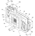
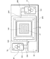
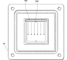
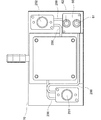
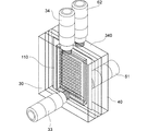
- FIG. 2 is an exploded perspective view of the cell incubator according to the embodiment. It is a perspective view of the cell incubator concerning embodiment. It is a front view of a part of cell culture device concerning an embodiment. It is a perspective view of a part of cell culture device concerning an embodiment. It is a front view of a part of cell culture device concerning an embodiment. It is a rear view of the cell incubator concerning embodiment.
- FIG. 2 is an exploded perspective view of the cell incubator according to the embodiment.
- FIG. 1 is a schematic diagram of a computer according to an embodiment. It is an example of the image of the cell mass according to the embodiment. It is an example of the image of the cell mass which carried out the binarization process which concerns on embodiment.
- FIG. 2 is an exploded perspective view of the cell incubator according to the first embodiment.
- FIG. 2 is a perspective view of the cell incubator according to the first embodiment.
- FIG. 9 is a micrograph of a cell mass according to Example 2.
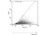
- 9 is a histogram showing the results of flow cytometry of iPS cells according to Example 2.
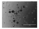
- 9 is a micrograph of a cell mass according to Example 3.
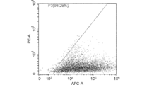
- 10 is a histogram showing the results of iPS cell flow cytometry according to Example 3.
- the cell incubator holds a culture component transmitting member 10 through which a culture component can pass, and a cell-containing medium that covers one surface of the culture component transmission member 10, and
- the apparatus includes a culture tank 30 for culturing, and a culture medium holding tank 40 that covers the other surface of the culture component permeable member 10 and holds a culture medium.
- the cell-containing medium in the culture tank 30 can contact the culture component permeable member 10. Further, the culture medium in the culture medium holding tank 40 can contact the culture component transmitting member 10.
- the medium in the medium holding tank 40 does not contain cells.
- the culture component transmitting member 10 allows the effective component of the culture medium in the culture medium holding tank 40 to penetrate into the cell-containing medium in the culture tank 30.
- the culture component transmitting member 10 may allow waste products in the cell-containing medium in the culture tank 30 to permeate into the medium in the medium holding tank 40.
- a semipermeable membrane and a mesh can be used as the culture component permeable member 10.
- Semi-permeable membranes include dialysis membranes.
- the molecular weight cut off of the semipermeable membrane is, for example, 0.1 KDa or more, 10 KDa or more, or 50 KDa or more.
- the semipermeable membrane includes, for example, cellulose ester, ethyl cellulose, cellulose esters, regenerated cellulose, polysulfone, polyacrylonitrile, polymethyl methacrylate, ethylene vinyl alcohol copolymer, polyester polymer alloy, polycarbonate, polyamide, cellulose acetate, cellulose diester. It is composed of acetate, cellulose triacetate, copper ammonium rayon, saponified cellulose, hemophan film, phosphatidylcholine film, vitamin E coating film and the like.
- the mesh When the culture component permeable member 10 is a mesh, the mesh has pores smaller than the cells or cell mass cultured in the culture tank 30. This prevents the cells or cell mass in the culture tank 30 from moving into the medium holding tank 40.
- the material of the mesh is, for example, resin and metal, but is not particularly limited.
- the surface of the culture component permeable member 10 may be non-cell-adhesive.
- the cell incubator according to the embodiment may further include a culture-side plate 21 and a culture-side plate 22 each having an opening and sandwiching the culture component permeable member 10.
- the culture-side plate 21 and the culture-side plate 22 are arranged so that the culture component permeable member 10 is prevented from changing due to the pressure of the cell-containing medium in the culture tank 30 and the medium in the medium holding tank 40. Is held, and the culture component transmitting member 10 is held. Thereby, contact of the culture component permeable member 10 with the inner wall of the culture tank 30 or the culture medium holding tank 40 due to the pressure fluctuation is suppressed.
- the culture-side plate 21 and the culture-side plate 22 have hardness that does not fluctuate due to the pressure received from the cell-containing medium in the culture tank 30 and the medium in the medium holding tank 40.
- the material of the culture side plate 21 and the medium side plate 22 is, for example, resin and metal, but is not particularly limited.
- the surface of the culture side plate 21 may be cell non-adhesive.
- the culture-side plate 21 is provided with an opening so that the cell-containing medium in the culture tank 30 can come into contact with the culture component transmitting member 10.
- an opening is provided in the culture medium side plate 22 so that the culture medium in the culture medium holding tank 40 can come into contact with the culture component transmitting member 10.
- the shape of the opening provided in each of the culture side plate 21 and the medium side plate 22 is, for example, a circle, but is not particularly limited.
- the openings provided in each of the culture side plate 21 and the culture medium side plate 22 have a size within a range in which the fluctuation of the culture component transmitting member 10 can be suppressed.
- the openings are provided in the culture-side plate 21 and the medium-side plate 22, for example, in a lattice shape or randomly.
- the culture side plate 21 may have a dark color such as black.
- the cells in the cell-containing medium can be visually recognized or imaged with high contrast with the culture side plate 21 as a background. If the size of the area of the culture-side plate 21 where the opening is not provided is larger than the cell or cell mass, the cell or the cell mass is raised with the background where the opening of the culture-side plate 21 is not provided as the background. It becomes easy to visually recognize the image or to make an image with the contrast. However, even if the culture component transmitting member 10 and the culture side plate 21 are transparent, the cells or the cell mass can be visually recognized or imaged by adjusting the light applied to the cells or the cell mass. is there.
- the culture tank 30 and the medium holding tank 40 may be fixed with screws, pins, electromagnets, or the like.
- the contact portion of the culture tank 30 and at least a part of one surface of the culture plate 21 are in close contact with each other.
- At least a part of the other surface of the culture side plate 21 and at least a part of one surface of the culture component transmitting member 10 are in close contact with each other.
- At least a part of the other surface of the culture component transmitting member 10 and at least a part of one surface of the culture plate 22 are in close contact with each other.
- At least a part of the other surface of the medium side plate 22 and the contact portion of the medium holding tank 40 are in close contact with each other.
- a packing or the like may be used as appropriate.
- the packing may be arranged, for example, between the culture component permeable member 10 and the culture tank 30.
- the packing may be disposed between the outer periphery of the culture component permeable member 10 and the culture tank 30.
- the outer diameter of the packing disposed between the culture component permeable member 10 and the culture tank 30 may be larger than the outer diameter of the culture component permeable member 10.
- the packing may be arranged between the culture component permeable member 10 and the culture medium holding tank 40, for example.
- the packing may be arranged between the outer periphery of the culture component transmitting member 10 and the culture medium holding tank 40.
- the outer diameter of the packing disposed between the culture component permeable member 10 and the culture medium holding tank 40 may be larger than the outer diameter of the culture component permeable member 10.
- the culture tank 30 includes, for example, a housing 31 and a cover 32 that covers the housing 31.
- the housing 31 and the cover 32 may be integrated.
- the inner wall of the culture tank 30 may be coated with a cell non-adhesive substance such as poly-HEMA (polyp2-hydroxyethyl methacrylate) to prevent cells from adhering, and the inner wall of the culture tank 30 may be made non-cell-adhesive.
- the housing 31 is provided with an opening 131 for exposing the culture component transmitting member 10 through the opening of the culture side plate 21.
- the cover 32 of the culture tank 30 is provided with a window 132 through which the cell-containing medium in the culture tank 30 can be observed.
- a material of the window 132 for example, glass and resin can be used.
- the cell incubator according to the embodiment may include a temperature controller for heating and cooling the window 132.
- the temperature control unit may be a transparent heater such as a transparent conductive film that is disposed on the window 132 and heats the window.
- the cell incubator according to the embodiment may include a temperature control unit for heating and cooling the housing 31 or the cover 32 of the culture tank 30.
- the temperature of the cell-containing medium in the culture tank 30 can be adjusted by adjusting the temperature of any one of the housing 31, the cover 32, and the window 132 with the temperature adjustment unit.
- the cell incubator according to the embodiment may further include a thermometer that measures the temperature of the cell-containing medium in the culture tank 30.
- the thermometer may measure the temperature of the cell-containing medium based on the temperature of the culture tank 30 without contacting the cell-containing medium, or may directly measure the temperature of the cell-containing medium by contacting the cell-containing medium. .
- the temperature control unit may be feedback-controlled so that the temperature of the cell-containing medium becomes a predetermined temperature.
- the temperature of the cell-containing medium is adjusted, for example, from 20 ° C to 45 ° C.
- the culture tank 30 is provided with a supply port 231 for supplying a fluid into the culture tank 30 and a discharge port 331 for discharging the fluid from the culture tank 30.
- a plug 33 shown in FIG. 2 to which a supply device such as a bag, a bellows, and a syringe for supplying a fluid can be connected is inserted into the supply port 231.
- the supply device may be a fluid machine such as a pump.
- the injection device may be directly connected to the supply port 231 shown in FIG.
- the supply device is detachable from the supply port 231, and when the supply device is not connected to the supply port 231, the supply port 231 can be sealed and exchange of fluid inside and outside of the culture tank 30 via the supply port 231 can be performed. Does not occur.
- the plug 33 may be a needleless connector.
- the needleless connector may be a split septum type or a mechanical valve type.
- the plug 33 includes a disk valve provided with a slit.
- a supply device or a flow path connected to the supply device is inserted into the slit of the disk valve.
- the slit is sealed.
- the disc valve is in close contact with the outer periphery of the supply device or the flow path connected to the supply device. Therefore, even when the supply device or the flow path connected to the supply device is inserted into the plug 33, the outside air does not enter the culture tank 30 via the plug 33.
- the plug 33 may be a connector into which a needle is inserted.
- the plug 34 shown in FIG. 2 to which a discharge device such as a bag, a bellows, and a syringe for discharging the fluid in the culture tank 30 can be connected is inserted into the discharge port 331.
- the ejector may be a fluid machine such as a pump.
- a discharger may be directly connected to the discharge port 331 shown in FIG.
- the ejector may actively suck the fluid in the culture tank 30.
- the ejector may passively increase the internal volume according to the pressure in the culture tank 30 and receive the fluid pushed out from the culture tank 30.
- the ejector can be attached to and detached from the outlet 331.
- Plug 34 may be a needleless connector.
- the needleless connector may be a split septum type or a mechanical valve type. Even when the ejector or the flow path connected to the ejector is inserted into the plug 34, the outside air does not enter the culture tank 30 via the plug 34.
- the plug 34 may be a connector into which a needle is inserted.
- the culture tank 30 is in a state in which the culture tank 30 is in close contact with the culture medium holding tank 40 with the culture side plate 21, the culture component transmitting member 10, and the culture medium side plate 22 interposed therebetween.
- the cell-containing medium is injected into the culture vessel 30 from the supply port 231 while the air in the culture vessel 30 is exhausted from the discharge port 331, whereby the cell-containing medium is put into the culture vessel 30 shown in FIG. It is possible. Further, it is possible to completely eliminate the air layer in the culture tank 30. However, an air layer may remain in the culture tank 30.
- the cell incubator according to the embodiment can hold the culture tank 30 and may further include a culture tank holding member capable of adjusting the inclination of the culture tank 30. By adjusting the inclination of the culture tank 30, it becomes easy to discharge gas such as air in the culture tank 30.
- the supply port 231 and the discharge port 331 of the culture tank 30 can be closed with a stopper or the like.
- the plug 33 and the plug 34 connected to the supply port 231 and the discharge port 331 of the culture tank 30 can be closed.
- the supply port 231 of the culture tank 30 may be shielded from the outside by being connected to the supply device, and the discharge port 331 of the culture tank 30 may be shielded from the outside by being connected to the discharger. It is possible.
- the supply port 231 and the discharge port 331 are closed and the culture tank 30 is brought into close contact with the culture medium holding tank 40 as shown in FIG. 2, the inside of the culture tank 30 is sealed from the air outside the culture tank 30.
- the predetermined range of the pH of the cell-containing medium is, for example, 6.0 to 9.0.
- cells can be cultured in a completely closed airtight space. Therefore, carbon dioxide gas, nitrogen gas, oxygen gas, and the like are actively supplied into the culture tank 30. It is not necessary. Therefore, it is not necessary to arrange the culture tank 30 in the CO 2 incubator.
- the culture tank 30 may be embedded with a gas impermeable material. In other words, the culture tank 30 may be embedded in a gas impermeable substance.
- Cells cultured in the culture tank 30 may be stem cells such as induced pluripotent stem (iPS) cells, embryonic stem cells (ES cells), and somatic stem cells, or may be cells other than stem cells. Good.
- the somatic stem cells may be mesenchymal stem cells.
- the stem cells may be expanded and cultured.
- the cells cultured in the culture tank 30 may be cells into which an inducing factor has been introduced, and may be cells induced into stem cells.
- the cells cultured in the culture tank 30 are cells into which the inducer has not been introduced, and the inducer is added to the cell-containing medium in the culture tank 30 to introduce the inducer into the cells. It may be induced into stem cells.
- the cells induced by the stem cells may be blood cells.
- the cells cultured in the culture tank 30 may be cells into which an inducing factor has been introduced, and may be cells that are induced by another type of cells.
- the cells cultured in the culture tank 30 are cells into which the inducer has not been introduced, and the inducer is added to the cell-containing medium in the culture tank 30 to introduce the inducer into the cells. It may be induced into cells. Inducing a differentiated cell into another kind of differentiated cell is sometimes referred to as transdifferentiation (or lineage reprogramming) or cell fate (cell fate reprogramming).
- the stem cells may be induced into the cells.
- the inducer may be RNA or protein. Inducers may be included, for example, in plasmids, Sendai viruses, adenoviruses, lentiviruses, and retroviruses.
- the cells cultured in the culture tank 30 may be cells that are not induced. Examples of cells cultured in the culture tank 30 include blood cells, neural cells, cardiomyocytes, epithelial cells, vascular endothelial cells, mesenchymal cells, fibroblasts, hepatocytes, insulin producing cells, Retinal pigment epithelial cells, corneal cells, and the like.
- Examples of blood cells include T cells, B cells, NK cells, NKT cells, megakaryocytes, macrophages, granulocytes, neutrophils, eosinophils, hematopoietic stem cells, blood stem / progenitor cells, erythrocytes, leukocytes and Platelets.
- Examples of neural cells include neural and glial cells, oligodendrocytes, neural stem cells.
- Examples of myocardial cells include myocardial stem cells, myocardial cells, and pacemaker cells.
- Examples of epithelial cells include keratinocytes, intestinal epithelial cells, oral epithelium, and corneal epithelial cell epithelial cells.
- mesenchymal cells include dermal cells, osteoblasts, adipocytes, muscle cells, chondrocytes and the like.
- the cells may form a cell mass (colony).
- the cells may be animal cells, including humans, insect cells, or plant cells.
- the cell-containing medium may be in the form of a gel.
- the cell-containing medium is gellan gum, deacylated gellan gum, hyaluronic acid, ramzan gum, diutan gum, xanthan gum, carrageenan, fucoidan, pectin, pectic acid, pectinic acid, heparan sulfate, heparin, heparin sulfate, keratosulfate, chondroitin. It may contain at least one polymer compound selected from the group consisting of sulfuric acid, deltaman sulfate, rhamnan sulfate, and salts thereof. Further, the cell-containing medium may contain methylcellulose. By including methylcellulose, aggregation between cells is further suppressed.
- the cell-containing medium is poly (glycerol monomethacrylate) (PGMA), poly (2-hydroxypropylmethacrylate) (PHPMA), Poly (N-isopropylacrylamide) (PNIPAM), amine terminated, carboxylic acid terminated, maleimide terminated, N-hydroxysuccinimide (NHS) ester terminated, triethoxysilane terminated, Poly (N-isopropylacrylamide-co-acrylic acid), Poly (N-isopropylacrylamide-co-acrylic acid), Poly (N-isopropylacrylamide-co-butylacrylate), Poly (N-isopropylacrylamide-co -methacrylic acid), Poly (N-isopropylacrylamide-co-methacrylic acid-co-octadecyl acrylate), and N-Isopropylacrylamide, which may contain a small number of temperature-sensitive gels.
- PGMA poly (glycerol monomethacrylate
- a gel medium or a gel medium includes a polymer medium.
- the culture medium holding tank 40 shown in FIG. 1 is provided with an opening 140 shown in FIG. 3 for exposing the culture component transmitting member 10 through the opening of the culture medium side plate 22.
- the opening 140 is covered with the culture component transmitting member 10 shown in FIG.
- the medium holding tank 40 shown in FIG. 3 is provided with an inlet 240 for introducing a fluid into the medium holding tank 40 and an outlet 340 for discharging the fluid from the medium holding tank 40.
- a plurality of current plates 41 may be arranged in the culture medium holding tank 40.
- the plurality of current plates 41 are arranged, for example, so as to alternately protrude from the opposed inner walls of the culture medium holding tank 40.
- the medium holding tank 40 is in a state of being in close contact with the culture tank 30 with the medium side plate 22, the culture component transmitting member 10, and the culture side plate 21 shown in FIG.
- the cell culture medium is injected into the culture medium holding tank 40 from the inlet 240 while discharging the air in the culture medium holding tank 40 from the discharge port 340 shown in FIG. It is possible to put the cell culture medium inside.
- the cell culture medium is injected into the culture medium holding tank 40 from the introduction port 240 while discharging the cell culture medium in the culture medium holding tank 40 from the outlet port 340. It is possible to flow the cell culture medium into the culture medium holding tank 40.
- the culture medium flows along the plurality of current plates 41 from the inlet 240 to the outlet 340 in the medium holding tank 40. Therefore, an opportunity for the components of the culture medium to come into contact with the culture component permeable member 10 is secured.
- one or a plurality of outlets 241 communicating with the inlet 240 shown in FIG. 3 may be provided on the inner wall of the culture medium holding tank 40.
- the plurality of discharge ports 241 shown in FIG. 4 are provided, for example, in a horizontal row.
- the number and arrangement of the plurality of discharge ports 241 may be arranged uniformly or randomly.
- the number and arrangement of the plurality of outlets 241 are set according to characteristics such as viscosity of the culture medium.
- FIG. 5 by discharging the culture medium from the plurality of discharge ports 241, it is possible to improve the uniformity of the culture medium in contact with the culture component transmitting member 10 in the culture medium holding tank 40.
- a discharge block 145 provided with one or more discharge ports 241 may be insertable into the inner wall of the culture medium holding tank 40.
- the ejection blocks 145 having different patterns such as the number and arrangement of the plurality of ejection ports 241 may be prepared and used depending on the characteristics of the culture medium and the cells to be cultured.
- the upper side of the inner wall of the culture medium holding tank 40 with respect to gravity may be bent or curved upward or downward.
- the lower side of the inner wall of the culture medium holding tank 40 with respect to gravity may be bent or curved upward or downward.
- openings 242 may be provided near the plurality of discharge ports 241 on the inner wall of the medium holding tank 40. As the culture medium discharged from the plurality of discharge ports 241 accumulates in the culture medium holding tank 40, the air in the culture medium holding tank 40 flows out of the opening 242 to the outside. After the culture medium is placed in the culture medium holding tank 40, the opening 242 may be closed.
- the culture medium channel 200 may include a resin tube, a silicon tube, or the like.
- the culture medium channel 200 may be embedded with a gas impermeable material.
- the culture medium channel 200 may be embedded in a gas impermeable substance.
- the culture medium channel 200 may be a hole provided in a member made of resin, glass, metal, or the like. In this case, for example, the medium channel 200 is formed by attaching members provided with concave portions to each other.
- the medium flow path 200 may be provided with a fluid machine for introducing a medium into the medium holding tank 40 and discharging the medium from the medium holding tank 40.
- the fluid machine includes, for example, an introduction fluid machine 51 for introducing a culture medium into the culture medium holding tank 40 and a discharge fluid machine 52 for discharging the culture medium from the culture medium holding tank 40.
- a positive displacement pump can be used as the introduction fluid machine 51 and the discharge fluid machine 52 shown in FIG.
- positive displacement pumps include reciprocating pumps, including piston pumps, plunger pumps, and diaphragm pumps, or rotary pumps, including gear, vane, and screw pumps.
- Examples of the diaphragm pump include a tubing pump and a piezoelectric (piezo) pump.
- the tubing pump is sometimes called a peristaltic pump.
- a microfluidic chip module in which various types of pumps are combined may be used.
- liquid can be sent without the pump directly contacting the medium inside the medium flow path 200 shown in FIG.
- a syringe pump may be used as the introduction fluid machine 51 and the discharge fluid machine 52.
- Even pumps other than hermetic pumps can be reused by heat sterilization or the like.
- the introduction fluid machine 51 When the introduction fluid machine 51 is a hermetic pump, the introduction fluid machine 51 includes a pump head 151 and a drive unit 251 such as a motor as shown in FIG.
- the pump head 151 and the drive unit 251 are detachable.
- the pump head 151 is provided with a roller for squeezing a medium flow path such as a tube from the outside.
- the driving unit 251 rotates the rollers of the pump head 151.
- the discharge fluid machine 52 When the discharge fluid machine 52 is a hermetic pump, the discharge fluid machine 52 includes a pump head 152 and a drive unit 252 such as a motor.
- the pump head 152 and the drive unit 252 are detachable.
- the pump head 152 is provided with a roller for squeezing a medium flow path such as a tube from the outside.
- the driving unit 252 rotates the rollers of the pump head 152.
- the culture medium channel 200 may be provided with a culture medium tank 60 in which a culture medium can be inserted.
- the culture medium that has entered the culture medium tank 60 from the culture medium flow path 200 flows out to the culture medium flow path 200 again.
- the capacity of the medium circulating between the medium flow path 200 and the medium holding tank 40 can be increased.
- the medium tank 60 may be provided with a supply port for supplying a fluid into the medium tank 60 and an outlet for discharging the fluid from the medium tank 60.
- a plug 61 shown in FIG. 6 to which a supply device such as a bag for supplying fluid, a bellows, a syringe, or the like can be connected is inserted into a supply port of the culture medium tank 60.
- the supply device may be a fluid machine such as a pump. However, a supply device may be directly connected to the supply port of the culture medium tank 60.
- the supply device is detachable from the supply port, and when the supply device is not connected to the supply port, the supply port can be hermetically sealed, and exchange of fluid inside and outside of the medium flow path 200 via the supply port does not occur.
- the supply port is shielded from the outside by being connected to the supply device.
- the plug 61 may be a needleless connector.
- the needleless connector may be a split septum type or a mechanical valve type. Even when the supply device or the flow path connected to the supply device is inserted into the plug 61, the outside air does not enter the medium tank 60 via the plug 61.
- the plug 61 may be a connector into which a needle is inserted.
- a plug 62 to which a discharger such as a bag, a bellows, and a syringe for discharging the fluid in the culture medium tank 60 is inserted into the discharge port of the culture medium tank 60.
- the ejector may be a fluid machine such as a pump.
- a discharger may be directly connected to the discharge port of the culture medium tank 60.
- the ejector may actively aspirate the fluid in the media flow path.
- the ejector may passively increase the internal volume in response to the pressure in the medium flow path and receive the fluid pushed out of the medium flow path.
- the ejector can be attached to and detached from the outlet, and when the ejector is not connected to the outlet, the outlet can be sealed so that exchange of fluid inside and outside the medium flow path 200 via the outlet does not occur.
- the outlet is shielded from the outside by being connected to the ejector.
- the plug 62 may be a needleless connector.
- the needleless connector may be a split septum type or a mechanical valve type. Even when the ejector or the flow path connected to the ejector is inserted into the plug 62, the outside air does not enter the medium tank 60 via the plug 62.
- the plug 62 may be a connector into which a needle is inserted.
- the medium holding tank 40 shown in FIG. 1 is in close contact with the culture tank 30 with the medium side plate 22, the culture component transmitting member 10, and the culture side plate 21 interposed therebetween, and the medium shown in FIG.
- the culture medium is discharged from the culture medium holding tank 40, the culture medium flow path 200 and the culture medium tank 60 through the outlet.
- the culture medium By injecting the culture medium into the culture medium holding tank 40, the culture medium channel 200 and the culture medium tank 60 from the supply port of the tank 60, it is possible to put the culture medium into the culture medium holding tank 40, the culture medium flow path 200 and the culture medium tank 60. is there.
- the air layer in the medium holding tank 40, the medium flow path 200, and the medium tank 60 may be completely eliminated, or the air layer may remain.
- the supply device may actively inject the culture medium into the culture medium flow channel 200, or the culture medium in the supply device may be sucked into the culture medium flow passage 200 which has been reduced in pressure by driving the fluid machine, and The internal volume may decrease passively.
- the ejector may actively suck the air in the culture medium channel 200, or the air in the culture medium channel 200, which has been increased in pressure by the driving of the fluid machine, flows into the ejector, and the inside of the ejector The volume may increase passively.
- the culture medium in the culture medium tank 60 is discharged from the supply opening of the culture medium tank 60 while the culture medium in the culture medium tank 60 is discharged from the discharge opening of the culture medium tank 60.
- the cell medium can be replaced in the medium tank 60.
- the feeder may actively inject a new culture medium into the culture medium flow path 200, or a new culture medium in the supply may be sucked into the culture flow path 200 which has been reduced in pressure by driving the fluid machine.
- the internal volume within may be passively reduced.
- the ejector may actively suck the old medium in the medium flow path 200, or the old medium in the medium flow path 200, which has been increased in pressure by driving the fluid machine, flows into the ejector, and May be passively increased.
- the supply port for supplying the culture medium into the culture medium channel 200 and the culture medium holding tank 40 and the discharge port for discharging the air from the culture medium flow path 200 and the culture medium holding tank 40 are provided in the culture medium tank 60 of the culture medium flow path 200. May be provided in a portion other than the portion where is provided.
- a supply port for supplying the culture medium into the culture medium channel 200 and the culture medium holding tank 40 and an outlet for discharging the air from the culture medium flow path 200 and the culture medium holding tank 40 are provided in the culture medium flow path 200. It may be.
- the cell incubator according to the embodiment may include a temperature controller for heating and cooling at least one of the medium holding tank 40, the medium flow path 200, and the medium tank 60.
- the temperature of the culture medium can be adjusted by adjusting the temperature of any one of the culture medium holding tank 40, the culture medium flow path 200, and the culture medium tank 60 with the temperature adjustment unit.
- the cell incubator according to the embodiment may further include a thermometer that measures the temperature of the medium.
- the thermometer may measure the temperature of the culture medium based on the temperature of at least one of the culture medium holding tank 40, the culture medium flow path 200, and the culture medium tank 60 without contacting the culture medium.
- the temperature may be measured directly.
- the temperature control unit may be feedback-controlled so that the temperature of the culture medium becomes a predetermined temperature.
- the temperature of the medium is adjusted to, for example, 4 ° C or more and 45 ° C or less, or 20 ° C or more and 45 ° C or less.
- the culture medium holding tank 40, the culture medium flow path 200, the pump head 151, the pump head 152, and the culture medium tank 60 may be stored in the flow path case 70.
- the culture medium holding tank 40, the culture medium flow path 200, the pump head 151, the pump head 152, and the culture medium tank 60 may be completely embedded in the gas impermeable substance.
- the culture medium channel 200 may be provided in a tunnel shape in the gas impermeable material.
- a hole for inserting a shaft into the pump head 151, a hole for inserting a shaft into the pump head 152, a hole for inserting the plug 61 into the supply port of the medium tank 60, and A hole for inserting the plug 62 is provided at the outlet of the culture medium tank 60.
- the hole for inserting the plug 61 into the supply port of the medium tank 60 and the hole for inserting the plug 62 into the outlet of the medium tank 60 may be able to be closed.
- the drive unit 251 of the introduction fluid machine 51 and the drive unit 252 of the discharge fluid machine 52 may be arranged on a substrate-shaped drive unit holding member 80.
- the drive unit holding member 80 is provided with a hole for inserting the plug 61 into the supply port of the culture tank 60 and a hole 82 for inserting the plug 62 into the discharge port of the culture tank 60.
- the hole for inserting the plug 61 into the supply port of the medium tank 60 and the hole 82 for inserting the plug 62 into the outlet of the medium tank 60 may be able to be closed.
- the drive unit holding member 80 is brought into close contact with the flow path case 70 via the packing 90 shown in FIG.
- the packing 90 suppresses air from entering the flow path case 70 from the contact portion between the flow path case 70 and the driving unit holding member 80.
- the culture medium may be introduced into the culture medium holding tank 40, and the fluid machine for discharging the culture medium from the culture medium holding tank 40 may be covered with a fluid machine outside air blocking member.
- the fluid machine outside air shutoff member includes an introduction fluid machine outside air shutoff member 351 that covers the drive unit 251 of the introduction fluid machine 51 disposed on the drive unit holding member 80, and a drive unit.
- a discharge fluid machine external air blocking member 352 that covers the drive unit 252 of the discharge fluid machine 52 disposed on the holding member 80.
- the flow path case 70 and the drive unit holding member 80 are detachable.
- the drive unit holding member 80 is brought into close contact with the flow path case 70, and the hole for inserting the plug 61 into the supply port of the culture tank 60 and the hole for inserting the plug 62 into the discharge port of the culture tank 60 are closed and introduced.
- the drive unit 251 of the fluid machine 51 is covered with the outside air blocking member 351 for the introduction fluid machine, and the drive unit 252 of the fluid machine 52 for discharge is covered with the outside air blocking member 352 for the discharge fluid machine, the inside of the flow path case 70 is formed. It is cut off from the outside air, and the outside air cannot enter the flow path case 70. Therefore, exchange of gas inside and outside the flow path case 70 does not occur.
- outside air does not enter the culture medium holding tank 40 and the culture medium flow path 200.
- the culture medium holding tank 40 and the culture flow path Fluctuations in the pH of the medium within 200 can be suppressed and kept within a predetermined range.
- the predetermined range of the pH of the medium is, for example, 6.0 to 9.0. According to the knowledge of the present inventors, since cells can be cultured in a completely closed airtight space, carbon dioxide gas, nitrogen gas, oxygen gas, etc. Need not be actively supplied.
- the medium holding tank 40 may be embedded with a gas impermeable substance. In other words, the culture medium holding tank 40 may be embedded in a gas impermeable substance.
- the plug 62 is inserted into the hole of the flow path case 70 for inserting the plug 61 into the supply port of the culture medium tank 60 and the discharge port of the culture medium tank 60.
- the hole of the flow path case 70 By closing the hole of the flow path case 70, the inside of the flow path case 70 is sealed, and the substance in the flow path case 70 is prevented from flowing out and the outside air entering the flow path case 70. It is possible to
- the flow path case 70 including the medium flow path 200 and the pump heads 151 and 152 therein is disposable.
- the driving unit holding member 80 holding the driving units 251 and 252 can be repeatedly used.
- the amount of the medium fed into the culture medium holding tank 40 by the introduction fluid machine 51 shown in FIG. 2 is the same as the amount of the medium discharged from the culture medium holding tank 40 by the discharge fluid machine 52.
- the introduction fluid machine 51 and the discharge fluid machine 52 are controlled.
- the introduction fluid machine 51 and the discharge fluid machine 52 may send the culture medium into the culture medium holding tank 40 at all times, or may send the culture medium at appropriate intervals.
- the flow rate of the medium sent into the medium holding tank 40 may or may not be constant.
- the medium and the cell mass in the medium are monitored by an imaging device, and the flow rate of the medium fed into the medium holding tank 40 is increased or decreased according to the state of the medium and the cell mass in the medium. May be.
- the start and end of the feeding of the medium may be started.
- the flow rate of the medium to be fed may be increased or decreased depending on the state of the medium and the cell mass in the medium.
- ⁇ ⁇ In a stirred medium, cells may randomly collide with each other and combine to form cell clusters (colonies) of various sizes. Therefore, homogeneity between colonies may not be maintained. Furthermore, in a colony that is too large, nutrients and growth factors may not reach the colony, resulting in differentiation and cell death from inside. On the other hand, a colony that is too small may not be suitable for subculture. On the other hand, in the culture tank 30 shown in FIG. 2, the flow rate of the culture medium is slow or the culture medium does not flow, so that the frequency of collision between cells is low. Therefore, clonality can be maintained in the colony.
- the cells are stem cells such as iPS cells
- stem cells such as iPS cells
- the frequency of collision between the stem cells is low, the size of the colony of the stem cells can be kept uniform.
- the cell incubator according to the embodiment may further include a photographing device such as a photo camera or a video camera that photographs the cell-containing medium in the culture tank 30 through the window 132 of the cover 32 of the culture tank 30.
- a photographing device such as a photo camera or a video camera that photographs the cell-containing medium in the culture tank 30 through the window 132 of the cover 32 of the culture tank 30.
- a pH indicator such as phenol red may be included in order to check the pH of the medium.
- the cell incubator photographs the cells in the culture tank 30 to differentiate the cells.
- the apparatus may further include a differentiation state monitoring device that monitors a state.
- the range of the cells is three-dimensionally widened, and thus the distance in the optical axis direction from the imaging device to each cell varies. . This can make it difficult to focus on all cells.
- the depth of field is increased by using a bright lens (a lens with a small F-number) or by irradiating a bright illumination on the object to be measured and imaging with the lens aperture as narrow as possible. It is possible.
- a plurality of images may be captured while the focal position of the lens is gradually changed, and the captured images may be combined to obtain a pseudo deeply focused image.
- each of the plurality of images is an image in which in-focus cells and out-of-focus blurred cells intersect. Therefore, one combined image may be generated by collecting focused partial images from a plurality of images.
- cells may be photographed through a telecentric lens. Since the telecentric lens makes the principal ray passing from the subject such as a cell or the like through the center of the lens aperture parallel to the lens optical axis, the distance from the photographing device to each of the plurality of cells in the culture tank 30 is not uniform. However, the size of the cell to be imaged does not change according to the distance.
- an illumination light source is arranged in a direction perpendicular to the optical axis of the imaging device or in a direction close to the imaging device from the perpendicular direction. It is preferable to use a scattered light illumination method for irradiating illumination light to cells in the interior. As a result, the scattered light due to the illumination light that has hit the cells reaches the imaging device, but the illumination light that has not hit the cells does not reach the imaging device. Therefore, in the image, the portion of the culture medium becomes relatively dark, and the portion of the cells becomes relatively bright.
- the illumination method is not limited to this as long as cells can be recognized in the image.
- the cell incubator includes a central processing unit (CPU) 500 including an image processing unit 501 that performs image processing on an image captured by an imaging device disposed in front of the culture tank 30. You may have.
- the input device 401 such as a keyboard and a mouse, and the output device 402 such as a monitor may be connected to the CPU 500.
- the CPU 500 receives an image from an imaging device arranged in front of the culture tank 30 shown in FIG. 2 via a bus, an image interface, and the like.
- the image processing unit 501 illustrated in FIG. 8 may include a contour definition unit 511 that defines a contour of a cell or a cell mass in a cell image.
- FIG. 9 is an example of an image of an iPS cell cluster taken in an enlarged manner via a macro zoom lens or the like. In the image shown in FIG. 9, the portion that looks like a white mass is the iPS cell mass, and the dark portion in the background is the medium.
- the luminance value of a pixel having a luminance value equal to or higher than a predetermined threshold value is set to a maximum luminance value such as 255, for example, and is set to a value lower than the predetermined threshold value.
- a binarization process that replaces the luminance value of the pixel having the luminance value with the lowest luminance value such as 0, for example, as shown in FIG.
- the inside of the mass also becomes black with the lowest brightness, and a portion where the inside of the cell or cell mass and the portion of the culture medium are connected may occur. Therefore, cells or cell clusters may not be extracted by the binarization process.
- the contour definition unit 511 shown in FIG. 8 allows the image of the cell to pass high-frequency components higher than a predetermined frequency included in the spatial frequency, block low-frequency components lower than the predetermined frequency, and reduce the luminance value.
- a high-pass filter that sets the minimum value such as 0 is applied.
- a high frequency component is included in a spatial frequency in a cell or a cell mass portion, and a low frequency component is included in a spatial frequency in a medium portion. Therefore, as shown in FIG.
- the luminance value of the medium portion becomes a minimum value such as 0, for example, and the luminance value of the cell or cell mass is The value becomes a relatively large value as compared with the portion of the medium. Therefore, the portion where the luminance does not reach the lowest value can be regarded as a cell or a cell mass.
- the contour definition unit 511 shown in FIG. 8 applies the watershed algorithm to the image to which the high-pass filter has been applied.
- the watershed algorithm considers the brightness gradient of the image as the undulation of the mountain, and determines the area where water flows from a high position (a position with a high brightness value or a low value) to a low position (a position with a low brightness value or a high brightness value).
- the image is divided so as to form one area.
- the contour definition unit 511 converts the image into the image using the DistanceTransform method.
- the Distance @ Transform method is an image conversion method in which the luminance value of each pixel of an image is replaced according to the distance to the nearest background pixel. For example, as shown in FIG. 12A, in the image to which the high-pass filter is applied, the brightness value of the medium region is collectively converted to 255, which is the highest brightness value, as shown in FIG. On a white background. Further, the luminance value of each pixel inside the cell region is converted to 0 or more and less than 255 according to the distance to the nearest background pixel. For example, as the distance from the nearest background pixel increases, the luminance value decreases.
- the contour definition unit 511 applies a watershed algorithm to the image converted by the Distance @ Transform method.
- a dark portion with low luminance is regarded as a mountain ridge, and when water is dropped from above in the vertical direction with respect to the image, as shown by an arrow in FIG.
- the flow of water flows is guessed, and as shown by the broken lines in FIG. 12C, points where water flowing from various directions collide are regarded as valleys, and the cell region is divided at the bottom of the valleys. I do.
- the image processing unit 501 illustrated in FIG. 8 may further include a cell evaluation unit 512.
- the cell evaluation unit 512 may issue a warning when the size of each cell mass is out of the appropriate range.
- the cell evaluation unit 512 may output that it is the time to subculture when the size of each cell mass becomes equal to or larger than a predetermined threshold.
- the circulation speed of the medium in the medium flow path may be changed by controlling the fluid machine of the cell incubator according to the calculated size of the cell mass. For example, the circulation rate of the medium may be increased as the size of the cell mass increases.
- the image processing unit 501 may further include a statistical processing unit 513 that statistically processes information obtained from the image-processed image.
- the statistical processing unit 513 may calculate, for example, a frequency distribution of the size or create a histogram for the cell cluster extracted by the contour definition unit 511.
- the statistical processing unit 513 may calculate the growth degree, the number, the congestion degree, and the like of the cell mass by continuously and regularly acquiring information on the cells. As a result, the state of the cell mass can be grasped quantitatively, and the culture result can be stabilized.
- the circulation speed of the medium in the medium flow path may be changed by controlling the fluid machine of the cell incubator according to the calculated number of cell masses. For example, the circulation rate of the medium may be increased as the number of cell clusters increases.
- the image processing unit 501 may further include a density calculation unit 514 that calculates the turbidity of the culture medium from the image of the culture medium and calculates the density of the cells or cell clusters in the culture medium based on the turbidity of the culture medium.
- a density calculation unit 514 that calculates the turbidity of the culture medium from the image of the culture medium and calculates the density of the cells or cell clusters in the culture medium based on the turbidity of the culture medium.
- the CPU 500 is connected to a relational storage device 403 including a volatile memory or a nonvolatile memory.
- the relationship storage device 403 stores, for example, a relationship between the turbidity of the medium and the density of cells or cell clusters in the medium, which is obtained in advance.
- the density calculator 514 reads out the relationship between turbidity and density from the relationship storage device 403. Further, the density calculation unit 514 calculates the density of the value of the cell or cell mass in the medium based on the turbidity value of the medium calculated from the image of the medium and the relationship between the turbidity and the density. Thereby, it is possible to non-destructively measure the density of the cells or the cell mass in the culture tank 30 without collecting the cell mass from the medium.
- the density calculation unit 514 determines the number of the extracted cells or cell clumps and the ratio of the volume of the region actually photographed by the photographing device to the total volume of the culture tank 30 in the culture medium. The value of the density of the cell or cell mass may be calculated.
- the density calculation unit 514 may output that it is time to pass. Furthermore, the density calculation unit 514 may calculate the density of cells or cell clusters in the medium over time, and calculate the growth rate of the cell clusters. An abnormal growth rate may indicate that the cell is abnormal. For example, the density calculator 514 issues a warning when an abnormal growth rate is calculated. In this case, the cell culture may be stopped.
- the density of cells or cell clusters in the medium increases and the distance between the cell clusters becomes too short, a plurality of cells or cell clusters may adhere to each other to form one large cell cluster.
- nutrients and hormones contained in the medium may not reach the inside, and the cells inside may be differentiated.
- the density of the cells or cell mass in the medium is lower than the suitable range, the growth rate of the cell mass and the ability to form the cell mass may be significantly reduced.
- the density calculation unit 514 it is possible to calculate the density of the cell or the cell mass, so that it is easy to determine whether the density of the cell or the cell mass is within a suitable range. Is possible. If the density of the cells or cell mass falls below a suitable range, it may be determined, for example, to stop the culture. Furthermore, the fluid machine of the cell incubator may be controlled in accordance with the calculated density of the cells or cell mass to change the circulation speed of the medium in the medium flow path. For example, as the density of cells or cell mass increases, the circulation rate of the medium may be increased.
- the image processing unit 501 may further include a medium evaluation unit 515 that evaluates a medium based on an image of a medium in which cells in the culture tank 30 of the cell incubator are cultured.
- the medium evaluation unit 515 performs image processing on the image of the medium, for example, and expresses the color of the medium using HSV using three parameters of hue (Hue), saturation (Saturation), and lightness (Value).
- the hue is a parameter corresponding to a concept generally called “hue” or “color”. Hue is generally expressed in units of angles.
- the relation storage device 403 stores the relation between the hue of the culture medium and the pH of the culture medium, which is obtained in advance.
- the culture medium evaluation unit 515 reads the relationship between the hue and the pH from the relationship storage device 403. Further, the culture medium evaluating unit 515 calculates the photographed culture medium pH value based on the culture medium hue value calculated from the culture medium image and the relationship between the hue and the pH. For example, the medium evaluation unit 515 may acquire an image of the medium over time and calculate the pH value of the medium.
- the medium evaluation unit 515 replaces the medium held in the medium holding tank 40 when the hue or the pH of the medium in which the cells in the culture tank 30 shown in FIG. 2 are out of the predetermined range. It may be determined to promote or to determine that contamination has occurred in the medium. In addition, replacing the medium includes partially replacing the medium and replenishing the medium.
- the medium evaluation unit 515 shown in FIG. 8 may calculate the growth rate of the cells from the change rate of the hue of the medium in which the cells in the culture tank 30 are cultured.
- the relationship storage device 403 stores a relationship between the change speed of the hue of the culture medium and the growth speed of the cells, which is acquired in advance.
- the culture medium evaluation unit 515 reads out the relationship between the hue change speed and the growth speed from the relationship storage device 403. Further, the medium evaluation unit 515 calculates the value of the cell growth rate based on the calculated value of the hue change rate and the relationship between the hue change rate and the growth rate.
- the cell incubator according to the embodiment for example, since cells are cultured in a completely closed system, it is possible to reduce the risk of cross-contamination due to leakage of cells from the culture device. Further, for example, even when cells are infected with a virus such as the HIV hepatitis virus, it is possible to reduce the risk of infection of the operator due to leakage of the cells. Further, it is possible to reduce the risk that the medium in the cell incubator is contaminated with bacteria, viruses, molds and the like in the air outside the cell incubator. Furthermore, according to the cell incubator according to the embodiment, it is possible to culture cells without using a CO 2 incubator.
- the culture medium flow path 200 may not be connected to the culture medium holding tank 40 shown in FIG.
- the differentiated cells such as blood cells may be reprogrammed into stem cells, or the stem cells may be induced into differentiated cells such as nerve cells.
- the cells may be subjected to suspension culture or adhesion culture. When cells are adhered and cultured, the surface of the culture side plate 21 shown in FIG.
- the present invention includes various embodiments and the like not described herein.
- Example 1 As shown in FIGS. 17 and 18, the semipermeable membrane 110 (Asahi Kasei Corporation or SPECTRUM) is sandwiched between the culture side plate 21 and the culture side plate 22, and further, the semipermeable membrane 110, the culture side plate 21 and the culture side plate 22 was sandwiched between the culture tank 30 and the medium holding tank 40.
- the semipermeable membrane 110 As shown in FIGS. 17 and 18, the semipermeable membrane 110 (Asahi Kasei Corporation or SPECTRUM) is sandwiched between the culture side plate 21 and the culture side plate 22, and further, the semipermeable membrane 110, the culture side plate 21 and the culture side plate 22 was sandwiched between the culture tank 30 and the medium holding tank 40.
- DMEM / F12 containing 20% alternative serum was gelled to prepare a gel medium.
- a cell-containing medium was prepared by adding 2 ⁇ 10 5 iPS cells / mL into single cells to the gel medium.
- the cell-containing medium was put into a syringe, and the syringe was connected to the supply port 231 of the culture tank 30 via the plug 33. An empty syringe was connected to the outlet 331 of the culture tank 30 via the plug 34.
- the cell-containing medium in the syringe was injected into the culture tank 30 from the supply port 231 of the culture tank 30. Due to the increase in the pressure in the culture tank 30, the piston of the syringe connected to the outlet 331 rises passively, and the air in the culture tank 30 moves into the syringe connected to the outlet 331 of the culture tank 30. .
- the cell-containing medium was injected into the culture tank 30 until the air layer in the culture tank 30 completely disappeared. Thereafter, the supply port 231 and the discharge port 331 of the culture tank 30 were shielded.
- the gel medium was put into a syringe, and the syringe was connected to the inlet 240 of the medium holding tank 40 via the plug 61. An empty syringe was connected to the outlet 340 of the culture medium holding tank 40 via the plug 62. Next, the gel medium in the syringe was injected into the medium holding tank 40 from the inlet 240 of the medium holding tank 40. The syringe connected to the outlet 340 of the medium holding tank 40 passively rises due to the pressure increase in the medium holding tank 40, and the air in the medium holding tank 40 is connected to the outlet 340 of the medium holding tank 40. Moved into the syringe.
- the gel medium was injected into the medium holding tank 40 until the air layer in the medium holding tank 40 completely disappeared. Thereafter, the inlet 240 and the outlet 340 of the culture medium holding tank 40 were shielded. Thereby, the inside of the culture tank 30 and the medium holding tank 40 was sealed, and the gas exchange between the inside and the outside of the culture tank 30 and the medium holding tank 40 was completely prevented.
- the suspension culture of iPS cells was started in the culture tank 30. Thereafter, once every two days, 2 mL of the gel medium in the medium holding tank 40 was replaced with 2 mL of a fresh gel medium. After 7 to 10 days from the start of the culture in the culture tank 30, the cell-containing medium in the culture tank 30 is discharged with a syringe, and the cell mass of iPS cells formed in the gel medium is collected using a filter. , Washed with PBS and placed in a Falcon tube. Furthermore, 500 ⁇ L of a cell dissociating enzyme (TrypLE Select, Thermo Fisher) was added to the cell mass, and the cell mass was incubated in a CO 2 incubator for 5 minutes.
- a cell dissociating enzyme TrypLE Select, Thermo Fisher
- the Falcon tube was taken out of the incubator, and 500 ⁇ L of the cell culture medium was placed in the Falcon tube, and the cell mass was suspended to make the iPS cells into a single cell.
- 2 mL of the cell culture medium was added to the Falcon tube, and the Falcon tube was centrifuged at 200 g using a centrifuge. After centrifugation, the supernatant in the Falcon tube was removed, and the iPS cells and the gel medium were placed in the Falcon tube to prepare a cell-containing medium. Thereafter, in the same manner as described above, the cell-containing medium was injected into the culture tank 30 and the iPS cells were subjected to suspension culture once every two days for 7 to 10 days while replacing the 2 mL gel medium in the medium holding tank 40.
- TRA-1-60 is a representative surface antigen of pluripotent stem cells, and it is known that the expression level is reduced in differentiated cells.
- the iPS cells on day 39 from the start of culture were 90% or more TRA-1-60 positive. Therefore, it was shown that stem cells can be cultured for a long period of time while maintaining pluripotency in an undifferentiated state without controlling the carbon dioxide concentration in the container when the container is sealed.
- a gel medium was prepared in the same manner as in Example 1. Single cell iPS cells were added to the gel medium. The gel medium containing iPS cells was placed in a 15 mL Falcon tube (Falcon). Thereafter, the cap of the Falcon tube was tightly closed.
- the Falcon tube was placed in an incubator having a carbon dioxide concentration of 5%, and suspension culture of iPS cells was started. Thereafter, once every two days, the cap of the Falcon tube was opened, and 2 mL of the gel medium was added into the Falcon tube. After the addition of the gel medium, the cap was closed as described above.
- the cap of the Falcon tube is opened, and the cell mass of iPS cells formed in the gel medium is collected using a filter, washed with PBS, and washed with PBS. Put in. Further, 500 ⁇ L of the cell dissociating enzyme was added to the cell mass, and the cell mass was incubated in a CO 2 incubator for 5 minutes. Next, the Falcon tube was taken out of the incubator, and 500 ⁇ L of a stem cell medium was placed in the Falcon tube, and the cell mass was suspended to make iPS cells into a single cell. 2 mL of the iPS medium was added to the Falcon tube, and the Falcon tube was centrifuged at 200 g using a centrifuge.
- iPS cells were subjected to suspension culture in a sealed Falcon tube for 7 to 10 days while adding a gel medium once every two days as described above.
- Example 2 A cell-containing medium was prepared in the same manner as in Example 1.
- a cell incubator similar to the cell incubator shown in FIG. 2 was prepared.
- the cell-containing medium was injected into the culture tank 30 until the air layer in the culture tank 30 completely disappeared. Thereafter, the supply port and the discharge port of the culture tank 30 were shielded. Further, the medium holding tank 40, the medium flow path 200, and the medium tank 60 were filled with a gel medium. Thereafter, the inlet and outlet of the medium tank 60 were shielded. Thereby, the inside of the culture tank 30 and the medium holding tank 40 was sealed, and the gas exchange between the inside and the outside of the culture tank 30 and the medium holding tank 40 was completely prevented.
- the gel medium was circulated in the medium holding tank 40, the medium flow path 200, and the medium tank 60, and the suspension culture of the iPS cells was started in the culture tank 30. Thereafter, once every two to six days, 10 mL of the gel medium in the medium tank 60 was replaced with 10 mL of fresh gel medium. After 7 to 10 days from the start of the culture in the culture tank 30, the cell-containing medium in the culture tank 30 is discharged with a syringe, subjected to the same subculture treatment as in Example 1, and the cells are cultured in the same manner as described above. The containing medium was injected into the culture tank 30 and the iPS cells were subjected to suspension culture for 7 to 10 days while changing the 10 mL gel medium in the medium tank 60 once every four days.
- Example 3 The growth factors were added to a medium (StemSpan H3000, registered trademark, STEMCELL Technologies Inc.), and deacylated gellan gum was further added to the medium to prepare a gel medium.
- a medium StemSpan H3000, registered trademark, STEMCELL Technologies Inc.
- the prepared gel medium was placed in a 15 mL tube, and 2 ⁇ 10 5 blood cells were seeded on the gel medium. Thereafter, the 15 mL tube was placed in a CO 2 incubator, and blood cells (monocytes) were cultured for 7 days. Thereafter, a Sendai virus vector (CytoTune-iPS2.0, ID Pharma Co., Ltd.) carrying OCT3 / 4, SOX2, KLF4, and cMYC was added to the gel medium so that the multiplicity of infection (MOI) became 10.0, and blood was added. Cells were infected with Sendai virus.
- a Sendai virus vector (CytoTune-iPS2.0, ID Pharma Co., Ltd.) carrying OCT3 / 4, SOX2, KLF4, and cMYC was added to the gel medium so that the multiplicity of infection (MOI) became 10.0, and blood was added. Cells were infected with Sendai virus.
- the Sendai virus was added to the gel medium, 15 mL of the gelled stem cell medium (DMEM / F12 containing 20% KnockOut @ SR (registered trademark, ThermoFisher @ SCIENTIFIC)) was added to the gel medium, and 15 mL of the Sendai virus was infected.
- the medium containing cells was put into the culture tank 30 shown in FIGS. 17 and 18, and the gel medium was injected into the medium holding tank 40.
- the insides of the culture tank 30 and the medium holding tank 40 were sealed, so that gas exchange did not completely occur between the inside and the outside of the culture tank 30 and the medium holding tank 40.
- TRA-1-60 was positive for 90% or more, and it was confirmed that reprogramming was almost complete. Therefore, it was shown that iPS cells can be induced from somatic cells other than stem cells without completely exchanging medium and gas in a completely closed environment.
Landscapes
- Health & Medical Sciences (AREA)
- Chemical & Material Sciences (AREA)
- Life Sciences & Earth Sciences (AREA)
- Engineering & Computer Science (AREA)
- Wood Science & Technology (AREA)
- Bioinformatics & Cheminformatics (AREA)
- Organic Chemistry (AREA)
- Zoology (AREA)
- General Engineering & Computer Science (AREA)
- Sustainable Development (AREA)
- Microbiology (AREA)
- Biochemistry (AREA)
- Biotechnology (AREA)
- General Health & Medical Sciences (AREA)
- Genetics & Genomics (AREA)
- Biomedical Technology (AREA)
- Analytical Chemistry (AREA)
- Clinical Laboratory Science (AREA)
- Immunology (AREA)
- Physics & Mathematics (AREA)
- Thermal Sciences (AREA)
- Computer Hardware Design (AREA)
- Molecular Biology (AREA)
- Apparatus Associated With Microorganisms And Enzymes (AREA)
- Micro-Organisms Or Cultivation Processes Thereof (AREA)
Abstract
Un incubateur de cellules est pourvu : d'un élément de perméation de composant de culture 10 dans lequel un composant de culture est perméable ; d'un réservoir de culture 30 pour cultiver des cellules qui recouvre une surface de l'élément de perméation de composant de culture 10 et qui contient un milieu contenant des cellules ; et d'un réservoir de stockage de milieu 40 qui est destiné à stocker un milieu et qui recouvre l'autre surface de l'élément de perméation de composant de culture 10.
Priority Applications (10)
| Application Number | Priority Date | Filing Date | Title |
|---|---|---|---|
| EP19851349.1A EP3842513A4 (fr) | 2018-08-20 | 2019-08-20 | Incubateur de cellules |
| US17/269,944 US11898130B2 (en) | 2018-08-20 | 2019-08-20 | Cell culture equipment |
| CN201980053224.XA CN112567016A (zh) | 2018-08-20 | 2019-08-20 | 细胞培养器 |
| JP2020538394A JP7280574B2 (ja) | 2018-08-20 | 2019-08-20 | 細胞培養器 |
| JP2023073491A JP7689674B2 (ja) | 2018-08-20 | 2023-04-27 | 細胞培養器 |
| JP2023073499A JP7688363B2 (ja) | 2018-08-20 | 2023-04-27 | 細胞培養器 |
| JP2023073489A JP7688362B2 (ja) | 2018-08-20 | 2023-04-27 | 細胞培養器 |
| US18/409,414 US12398357B2 (en) | 2018-08-20 | 2024-01-10 | Cell culture equipment |
| US19/240,580 US20250304899A1 (en) | 2018-08-20 | 2025-06-17 | Cell culture equipment |
| US19/240,656 US20250304900A1 (en) | 2018-08-20 | 2025-06-17 | Cell culture equipment |
Applications Claiming Priority (2)
| Application Number | Priority Date | Filing Date | Title |
|---|---|---|---|
| US201862766597P | 2018-08-20 | 2018-08-20 | |
| US62/766,597 | 2018-08-20 |
Related Child Applications (2)
| Application Number | Title | Priority Date | Filing Date |
|---|---|---|---|
| US17/269,944 A-371-Of-International US11898130B2 (en) | 2018-08-20 | 2019-08-20 | Cell culture equipment |
| US18/409,414 Continuation US12398357B2 (en) | 2018-08-20 | 2024-01-10 | Cell culture equipment |
Publications (1)
| Publication Number | Publication Date |
|---|---|
| WO2020040118A1 true WO2020040118A1 (fr) | 2020-02-27 |
Family
ID=69591191
Family Applications (1)
| Application Number | Title | Priority Date | Filing Date |
|---|---|---|---|
| PCT/JP2019/032384 Ceased WO2020040118A1 (fr) | 2018-08-20 | 2019-08-20 | Incubateur de cellules |
Country Status (5)
| Country | Link |
|---|---|
| US (4) | US11898130B2 (fr) |
| EP (1) | EP3842513A4 (fr) |
| JP (4) | JP7280574B2 (fr) |
| CN (1) | CN112567016A (fr) |
| WO (1) | WO2020040118A1 (fr) |
Cited By (5)
| Publication number | Priority date | Publication date | Assignee | Title |
|---|---|---|---|---|
| WO2021038996A1 (fr) * | 2019-08-29 | 2021-03-04 | ファナック株式会社 | Dispositif de production de cellule et méthode de production de cellule |
| WO2024150581A1 (fr) * | 2023-01-12 | 2024-07-18 | パナソニックIpマネジメント株式会社 | Appareil de culture cellulaire et récipient de culture |
| WO2024150584A1 (fr) * | 2023-01-12 | 2024-07-18 | パナソニックIpマネジメント株式会社 | Dispositif de culture cellulaire et récipient de culture |
| WO2024150585A1 (fr) * | 2023-01-12 | 2024-07-18 | パナソニックIpマネジメント株式会社 | Récipient de culture et dispositif de culture cellulaire |
| WO2026110903A1 (fr) * | 2024-11-25 | 2026-05-28 | Ube株式会社 | Dispositif et procédé de culture cellulaire |
Families Citing this family (1)
| Publication number | Priority date | Publication date | Assignee | Title |
|---|---|---|---|---|
| JP7280574B2 (ja) * | 2018-08-20 | 2023-05-24 | アイ ピース,インコーポレイテッド | 細胞培養器 |
Citations (15)
| Publication number | Priority date | Publication date | Assignee | Title |
|---|---|---|---|---|
| JPH06181749A (ja) * | 1992-09-02 | 1994-07-05 | Heraeus Sepatech Gmbh | 細胞培養用培養容器 |
| JPH11501866A (ja) * | 1995-03-15 | 1999-02-16 | ヘンリイ ビイ コプフ | 濾過カセットとこれを積層したフィルタ |
| JP2006030465A (ja) * | 2004-07-14 | 2006-02-02 | Taiei Denki Kk | 生細胞観察用ディッシュ |
| JP2006304733A (ja) * | 2005-05-02 | 2006-11-09 | Teijin Ltd | 細胞培養器 |
| JP2008017716A (ja) * | 2006-07-10 | 2008-01-31 | Takagi Ind Co Ltd | 細胞又は組織の培養方法 |
| JP4183742B1 (ja) | 2005-12-13 | 2008-11-19 | 国立大学法人京都大学 | 誘導多能性幹細胞の製造方法 |
| JP2011004613A (ja) * | 2009-06-23 | 2011-01-13 | Cellseed Inc | 採取物調製用パーソナルボックスおよび採取物調製システムならびに採取物調製方法 |
| JP2012147678A (ja) * | 2009-05-14 | 2012-08-09 | Otake:Kk | 一検体用多重培養装置 |
| WO2013114845A1 (fr) * | 2012-02-01 | 2013-08-08 | 東洋製罐グループホールディングス株式会社 | Nécessaire de culture cellulaire et son procédé d'utilisation |
| JP2014064475A (ja) * | 2012-09-24 | 2014-04-17 | Terumo Corp | 膜状組織の保存輸送容器および保存輸送方法 |
| JP2014114997A (ja) | 2012-12-07 | 2014-06-26 | Koken Ltd | 局所空気清浄化装置 |
| WO2015122528A1 (fr) * | 2014-02-17 | 2015-08-20 | 旭化成株式会社 | Dispositif de culture cellulaire |
| WO2017038887A1 (fr) * | 2015-08-31 | 2017-03-09 | アイ・ピース株式会社 | Système de production de cellules souches pluripotentes |
| WO2017056695A1 (fr) * | 2015-09-29 | 2017-04-06 | 株式会社日立製作所 | Appareil de culture cellulaire |
| WO2018003073A1 (fr) * | 2016-06-30 | 2018-01-04 | 株式会社サンプラテック | Ensemble destiné au transport d'un récipient de culture et unité permettant le transport de cellule ou de tissu biologique |
Family Cites Families (11)
| Publication number | Priority date | Publication date | Assignee | Title |
|---|---|---|---|---|
| US4748124A (en) | 1984-10-30 | 1988-05-31 | E. I. Du Pont De Nemours And Company | Compartmentalized cell-culture device and method |
| US5262320A (en) * | 1990-06-18 | 1993-11-16 | Massachusetts Institute Of Technology | Cell-culturing apparatus and method employing a macroporous support |
| US8507266B2 (en) * | 2003-11-04 | 2013-08-13 | Case Western Reserve University | Apparatus and method for tissue engineering |
| CN1763173A (zh) * | 2005-07-21 | 2006-04-26 | 高春平 | 造血干细胞培养装置和方法 |
| CN201626959U (zh) * | 2010-02-01 | 2010-11-10 | 中国农业科学院北京畜牧兽医研究所 | 用于细胞培养的微灌流装置 |
| US20130157353A1 (en) | 2010-05-12 | 2013-06-20 | Xpand Biotechnology B.V. | Cell-culture-bag |
| CN104480008A (zh) * | 2014-11-26 | 2015-04-01 | 中国科学院深圳先进技术研究院 | 用于细胞长时程培养的半透膜自动微渗透装置及系统 |
| WO2016093321A1 (fr) * | 2014-12-11 | 2016-06-16 | 株式会社アイカムス・ラボ | Procédé de culture cellulaire et dispositif de culture cellulaire |
| CN107365801B (zh) * | 2017-09-08 | 2019-11-01 | 天津博裕力牧科技有限公司 | 处理牛体细胞克隆胚的方法 |
| CN108334860A (zh) * | 2018-03-01 | 2018-07-27 | 北京航空航天大学 | 细胞图像的处理方法和装置 |
| JP7280574B2 (ja) * | 2018-08-20 | 2023-05-24 | アイ ピース,インコーポレイテッド | 細胞培養器 |
-
2019
- 2019-08-20 JP JP2020538394A patent/JP7280574B2/ja active Active
- 2019-08-20 EP EP19851349.1A patent/EP3842513A4/fr active Pending
- 2019-08-20 WO PCT/JP2019/032384 patent/WO2020040118A1/fr not_active Ceased
- 2019-08-20 US US17/269,944 patent/US11898130B2/en active Active
- 2019-08-20 CN CN201980053224.XA patent/CN112567016A/zh active Pending
-
2023
- 2023-04-27 JP JP2023073491A patent/JP7689674B2/ja active Active
- 2023-04-27 JP JP2023073489A patent/JP7688362B2/ja active Active
- 2023-04-27 JP JP2023073499A patent/JP7688363B2/ja active Active
-
2024
- 2024-01-10 US US18/409,414 patent/US12398357B2/en active Active
-
2025
- 2025-06-17 US US19/240,656 patent/US20250304900A1/en active Pending
- 2025-06-17 US US19/240,580 patent/US20250304899A1/en active Pending
Patent Citations (15)
| Publication number | Priority date | Publication date | Assignee | Title |
|---|---|---|---|---|
| JPH06181749A (ja) * | 1992-09-02 | 1994-07-05 | Heraeus Sepatech Gmbh | 細胞培養用培養容器 |
| JPH11501866A (ja) * | 1995-03-15 | 1999-02-16 | ヘンリイ ビイ コプフ | 濾過カセットとこれを積層したフィルタ |
| JP2006030465A (ja) * | 2004-07-14 | 2006-02-02 | Taiei Denki Kk | 生細胞観察用ディッシュ |
| JP2006304733A (ja) * | 2005-05-02 | 2006-11-09 | Teijin Ltd | 細胞培養器 |
| JP4183742B1 (ja) | 2005-12-13 | 2008-11-19 | 国立大学法人京都大学 | 誘導多能性幹細胞の製造方法 |
| JP2008017716A (ja) * | 2006-07-10 | 2008-01-31 | Takagi Ind Co Ltd | 細胞又は組織の培養方法 |
| JP2012147678A (ja) * | 2009-05-14 | 2012-08-09 | Otake:Kk | 一検体用多重培養装置 |
| JP2011004613A (ja) * | 2009-06-23 | 2011-01-13 | Cellseed Inc | 採取物調製用パーソナルボックスおよび採取物調製システムならびに採取物調製方法 |
| WO2013114845A1 (fr) * | 2012-02-01 | 2013-08-08 | 東洋製罐グループホールディングス株式会社 | Nécessaire de culture cellulaire et son procédé d'utilisation |
| JP2014064475A (ja) * | 2012-09-24 | 2014-04-17 | Terumo Corp | 膜状組織の保存輸送容器および保存輸送方法 |
| JP2014114997A (ja) | 2012-12-07 | 2014-06-26 | Koken Ltd | 局所空気清浄化装置 |
| WO2015122528A1 (fr) * | 2014-02-17 | 2015-08-20 | 旭化成株式会社 | Dispositif de culture cellulaire |
| WO2017038887A1 (fr) * | 2015-08-31 | 2017-03-09 | アイ・ピース株式会社 | Système de production de cellules souches pluripotentes |
| WO2017056695A1 (fr) * | 2015-09-29 | 2017-04-06 | 株式会社日立製作所 | Appareil de culture cellulaire |
| WO2018003073A1 (fr) * | 2016-06-30 | 2018-01-04 | 株式会社サンプラテック | Ensemble destiné au transport d'un récipient de culture et unité permettant le transport de cellule ou de tissu biologique |
Cited By (5)
| Publication number | Priority date | Publication date | Assignee | Title |
|---|---|---|---|---|
| WO2021038996A1 (fr) * | 2019-08-29 | 2021-03-04 | ファナック株式会社 | Dispositif de production de cellule et méthode de production de cellule |
| WO2024150581A1 (fr) * | 2023-01-12 | 2024-07-18 | パナソニックIpマネジメント株式会社 | Appareil de culture cellulaire et récipient de culture |
| WO2024150584A1 (fr) * | 2023-01-12 | 2024-07-18 | パナソニックIpマネジメント株式会社 | Dispositif de culture cellulaire et récipient de culture |
| WO2024150585A1 (fr) * | 2023-01-12 | 2024-07-18 | パナソニックIpマネジメント株式会社 | Récipient de culture et dispositif de culture cellulaire |
| WO2026110903A1 (fr) * | 2024-11-25 | 2026-05-28 | Ube株式会社 | Dispositif et procédé de culture cellulaire |
Also Published As
| Publication number | Publication date |
|---|---|
| US20250304900A1 (en) | 2025-10-02 |
| EP3842513A4 (fr) | 2022-06-29 |
| US12398357B2 (en) | 2025-08-26 |
| JP7688362B2 (ja) | 2025-06-04 |
| JP2023086913A (ja) | 2023-06-22 |
| JP7688363B2 (ja) | 2025-06-04 |
| JPWO2020040118A1 (ja) | 2021-08-10 |
| JP2023086915A (ja) | 2023-06-22 |
| CN112567016A (zh) | 2021-03-26 |
| EP3842513A1 (fr) | 2021-06-30 |
| JP2023086914A (ja) | 2023-06-22 |
| US20240141273A1 (en) | 2024-05-02 |
| JP7689674B2 (ja) | 2025-06-09 |
| US20210222107A1 (en) | 2021-07-22 |
| US20250304899A1 (en) | 2025-10-02 |
| JP7280574B2 (ja) | 2023-05-24 |
| US11898130B2 (en) | 2024-02-13 |
Similar Documents
| Publication | Publication Date | Title |
|---|---|---|
| JP7689674B2 (ja) | 細胞培養器 | |
| US11912977B2 (en) | Pluripotent stem cell production system | |
| US11959058B2 (en) | Cell processing system and cell processing device | |
| WO2020040135A1 (fr) | Procédé permettant de cultiver ou d'induire des cellules | |
| HK40043277A (en) | Cell incubator | |
| JP7090337B2 (ja) | 細胞処理システム及び細胞処理装置 | |
| JP6530577B1 (ja) | 細胞処理システム及び細胞処理装置 | |
| JP6530874B1 (ja) | 細胞処理システム及び細胞処理装置 | |
| HK40078284A (en) | Cell processing device | |
| HK40011741A (en) | Cell processing system and cell processing device |
Legal Events
| Date | Code | Title | Description |
|---|---|---|---|
| 121 | Ep: the epo has been informed by wipo that ep was designated in this application |
Ref document number: 19851349 Country of ref document: EP Kind code of ref document: A1 |
|
| DPE1 | Request for preliminary examination filed after expiration of 19th month from priority date (pct application filed from 20040101) | ||
| ENP | Entry into the national phase |
Ref document number: 2020538394 Country of ref document: JP Kind code of ref document: A |
|
| NENP | Non-entry into the national phase |
Ref country code: DE |
|
| ENP | Entry into the national phase |
Ref document number: 2019851349 Country of ref document: EP Effective date: 20210322 |