WO2020040207A1 - Élément de plateau pour traitement thermique et structure stratifiée pour traitement thermique - Google Patents
Élément de plateau pour traitement thermique et structure stratifiée pour traitement thermique Download PDFInfo
- Publication number
- WO2020040207A1 WO2020040207A1 PCT/JP2019/032662 JP2019032662W WO2020040207A1 WO 2020040207 A1 WO2020040207 A1 WO 2020040207A1 JP 2019032662 W JP2019032662 W JP 2019032662W WO 2020040207 A1 WO2020040207 A1 WO 2020040207A1
- Authority
- WO
- WIPO (PCT)
- Prior art keywords
- tray
- heat treatment
- support
- component
- base
- Prior art date
- Legal status (The legal status is an assumption and is not a legal conclusion. Google has not performed a legal analysis and makes no representation as to the accuracy of the status listed.)
- Ceased
Links
Images










Classifications
-
- C—CHEMISTRY; METALLURGY
- C21—METALLURGY OF IRON
- C21D—MODIFYING THE PHYSICAL STRUCTURE OF FERROUS METALS; GENERAL DEVICES FOR HEAT TREATMENT OF FERROUS OR NON-FERROUS METALS OR ALLOYS; MAKING METAL MALLEABLE, e.g. BY DECARBURISATION OR TEMPERING
- C21D1/00—General methods or devices for heat treatment, e.g. annealing, hardening, quenching or tempering
- C21D1/06—Surface hardening
-
- C—CHEMISTRY; METALLURGY
- C21—METALLURGY OF IRON
- C21D—MODIFYING THE PHYSICAL STRUCTURE OF FERROUS METALS; GENERAL DEVICES FOR HEAT TREATMENT OF FERROUS OR NON-FERROUS METALS OR ALLOYS; MAKING METAL MALLEABLE, e.g. BY DECARBURISATION OR TEMPERING
- C21D1/00—General methods or devices for heat treatment, e.g. annealing, hardening, quenching or tempering
-
- C—CHEMISTRY; METALLURGY
- C21—METALLURGY OF IRON
- C21D—MODIFYING THE PHYSICAL STRUCTURE OF FERROUS METALS; GENERAL DEVICES FOR HEAT TREATMENT OF FERROUS OR NON-FERROUS METALS OR ALLOYS; MAKING METAL MALLEABLE, e.g. BY DECARBURISATION OR TEMPERING
- C21D9/00—Heat treatment, e.g. annealing, hardening, quenching or tempering, adapted for particular articles; Furnaces therefor
- C21D9/32—Heat treatment, e.g. annealing, hardening, quenching or tempering, adapted for particular articles; Furnaces therefor for gear wheels, worm wheels, or the like
-
- C—CHEMISTRY; METALLURGY
- C23—COATING METALLIC MATERIAL; COATING MATERIAL WITH METALLIC MATERIAL; CHEMICAL SURFACE TREATMENT; DIFFUSION TREATMENT OF METALLIC MATERIAL; COATING BY VACUUM EVAPORATION, BY SPUTTERING, BY ION IMPLANTATION OR BY CHEMICAL VAPOUR DEPOSITION, IN GENERAL; INHIBITING CORROSION OF METALLIC MATERIAL OR INCRUSTATION IN GENERAL
- C23C—COATING METALLIC MATERIAL; COATING MATERIAL WITH METALLIC MATERIAL; SURFACE TREATMENT OF METALLIC MATERIAL BY DIFFUSION INTO THE SURFACE, BY CHEMICAL CONVERSION OR SUBSTITUTION; COATING BY VACUUM EVAPORATION, BY SPUTTERING, BY ION IMPLANTATION OR BY CHEMICAL VAPOUR DEPOSITION, IN GENERAL
- C23C8/00—Solid state diffusion of only non-metal elements into metallic material surfaces; Chemical surface treatment of metallic material by reaction of the surface with a reactive gas, leaving reaction products of surface material in the coating, e.g. conversion coatings, passivation of metals
- C23C8/06—Solid state diffusion of only non-metal elements into metallic material surfaces; Chemical surface treatment of metallic material by reaction of the surface with a reactive gas, leaving reaction products of surface material in the coating, e.g. conversion coatings, passivation of metals using gases
- C23C8/08—Solid state diffusion of only non-metal elements into metallic material surfaces; Chemical surface treatment of metallic material by reaction of the surface with a reactive gas, leaving reaction products of surface material in the coating, e.g. conversion coatings, passivation of metals using gases only one element being applied
- C23C8/20—Carburising
-
- C—CHEMISTRY; METALLURGY
- C23—COATING METALLIC MATERIAL; COATING MATERIAL WITH METALLIC MATERIAL; CHEMICAL SURFACE TREATMENT; DIFFUSION TREATMENT OF METALLIC MATERIAL; COATING BY VACUUM EVAPORATION, BY SPUTTERING, BY ION IMPLANTATION OR BY CHEMICAL VAPOUR DEPOSITION, IN GENERAL; INHIBITING CORROSION OF METALLIC MATERIAL OR INCRUSTATION IN GENERAL
- C23C—COATING METALLIC MATERIAL; COATING MATERIAL WITH METALLIC MATERIAL; SURFACE TREATMENT OF METALLIC MATERIAL BY DIFFUSION INTO THE SURFACE, BY CHEMICAL CONVERSION OR SUBSTITUTION; COATING BY VACUUM EVAPORATION, BY SPUTTERING, BY ION IMPLANTATION OR BY CHEMICAL VAPOUR DEPOSITION, IN GENERAL
- C23C8/00—Solid state diffusion of only non-metal elements into metallic material surfaces; Chemical surface treatment of metallic material by reaction of the surface with a reactive gas, leaving reaction products of surface material in the coating, e.g. conversion coatings, passivation of metals
- C23C8/06—Solid state diffusion of only non-metal elements into metallic material surfaces; Chemical surface treatment of metallic material by reaction of the surface with a reactive gas, leaving reaction products of surface material in the coating, e.g. conversion coatings, passivation of metals using gases
- C23C8/08—Solid state diffusion of only non-metal elements into metallic material surfaces; Chemical surface treatment of metallic material by reaction of the surface with a reactive gas, leaving reaction products of surface material in the coating, e.g. conversion coatings, passivation of metals using gases only one element being applied
- C23C8/20—Carburising
- C23C8/22—Carburising of ferrous surfaces
-
- F—MECHANICAL ENGINEERING; LIGHTING; HEATING; WEAPONS; BLASTING
- F27—FURNACES; KILNS; OVENS; RETORTS
- F27D—DETAILS OR ACCESSORIES OF FURNACES, KILNS, OVENS OR RETORTS, IN SO FAR AS THEY ARE OF KINDS OCCURRING IN MORE THAN ONE KIND OF FURNACE
- F27D3/00—Charging; Discharging; Manipulation of charge
- F27D3/12—Travelling or movable supports or containers for the charge
-
- B—PERFORMING OPERATIONS; TRANSPORTING
- B22—CASTING; POWDER METALLURGY
- B22C—FOUNDRY MOULDING
- B22C9/00—Moulds or cores; Moulding processes
- B22C9/02—Sand moulds or like moulds for shaped castings
- B22C9/04—Use of lost patterns
Definitions
- the present invention relates to a tray member for heat treatment and a laminated structure for heat treatment. More specifically, the present invention provides a heat treatment tray member that can be used for a long time by suppressing the occurrence of deformation and cracking even when a component is placed and repeatedly placed in a heat treatment furnace for heat treatment of the component. And a laminated structure for heat treatment obtained by laminating them.
- Carburizing treatment is known as a surface hardening treatment for metal parts.
- Carburizing is a process in which carbon monoxide (CO) gas generated from a carburizing agent is brought into contact with steel at a high temperature to infiltrate and diffuse carbon into metal parts to form a surface layer (carburized layer). is there.
- CO carbon monoxide
- a metal part made of low carbon steel or the like having a low carbon content is subjected to quenching and tempering after carburizing, only the surface layer is hardened.
- the resulting metal product is composed of a wear-resistant surface layer and a tough core.
- a member such as a tray or a grid for mounting a metal component to be processed is used.
- the carburizing furnace member is exposed to carburizing gas for a long time in a carburizing furnace at 800 to 1000 ° C. Further, since the carburizing furnace member is used repeatedly, it is repeatedly exposed to the carburizing gas at a high temperature. Further, since heating and cooling are generally repeated in a carburizing furnace, the members for the carburizing furnace are placed in an extremely severe temperature environment.
- FIG. 22 shows a tray member 100 for a carburizing furnace currently used.
- the carburizing furnace tray member 100 includes a quadrilateral base 111, a plurality of component receivers 120 having a complicated shape disposed on the base 111, a corner support 112 provided at each corner of the base 111, and a base 111. And a center support 129 provided in the vicinity of the center.
- a first cause is that a hard and brittle carburized layer containing chromium carbide or cementite is formed thickly in a steel material constituting a member for a carburizing furnace by repeatedly performing carburizing treatment.
- the carburizing furnace member on which the thick carburizing layer is formed is easily deformed or cracked by expansion and shrinkage stress caused by heating and cooling.
- a member for a carburizing furnace in which deformation or cracks have occurred may eventually break and become unusable.
- the second cause is that chromium carbide or cementite grows throughout the carburized layer thickly formed on the carburizing furnace member due to further repetition of the carburizing treatment, and the volume of the carburized layer expands. .
- the entire shape of the carburizing furnace member is largely deformed by the expansion of the volume of the carburizing layer. Then, the member for the carburizing furnace that is greatly deformed becomes difficult to use, and if the deformation is to be corrected, the member may be broken because the carburized layer is embrittled.
- Patent Document 1 proposes a heat-resistant alloy having excellent high-temperature strength and corrosion resistance and excellent carburization resistance and coking resistance even in a thermal decomposition environment in which carburization and oxidation are repeated.
- Patent Document 2 proposes a calorizing treatment for the purpose of providing a member or a jig that can be stably used for a long period of time in a gas carburizing furnace under an environment with severe thermal shock.
- the member or jig that has been subjected to the calorizing treatment has improved carburization resistance, is stable with little carburization even when used for a long time in a gas carburizing furnace under a severe environment, and has a long life. It can be extended significantly.
- the present applicant can impart excellent carburization resistance at low cost to an iron alloy base material constituting a member for a carburizing furnace (a member such as a tray or a grid) used in a carburizing furnace. Proposal of technology that can be done.
- Patent Document 4 proposes that instead of stainless steel or heat-resistant cast steel, a C / C composite, which is a carbon-based composite material, be used as a heat treatment jig for carburizing or carbonitriding. Due to this material change, the heat treatment jig is not affected by carburization or nitriding, has excellent high-temperature strength, has excellent durability to withstand thermal shock during rapid heating and quenching, and does not thermally deform. It is stated that the heat capacity can be reduced based on the weight reduction.
- the tray on which the article to be processed is mounted is formed of a carbon-based composite material (C / C composite), thereby preventing carburization of the tray and extending its life.
- a spacer plate made of a non-carburizing material is interposed between the tray formed of the carbon-based composite material and the article to be processed, thereby causing the carbon component contained in the carbon-based composite material to adversely affect the article to be processed.
- Patent Literature 1 and Patent Literature 2 use a high-cost nickel-base heat-resistant alloy, apply a calorizing treatment using a special treatment agent or a container, or the like, and manufacture a tray member for a carburizing furnace. This significantly increases costs.
- the technique disclosed in Patent Document 3 is a treatment method capable of imparting excellent carburization resistance to a carburizing furnace tray member at a low cost, but is required to be able to be used for a longer period of time, and further added value and cost reduction are required. Have been.
- Patent Document 4 discloses that a carbon component contained in a carbon-based composite material is applied to an article to be processed by interposing a spacer plate made of a hard carburizing material between a tray formed of a carbon-based composite material and the article to be processed. It is not expected to have any adverse effects. However, since the article to be heat-treated is placed on the spacer plate made of the hardly carburizing material without any care, the articles to be heat-treated come into contact with each other, and carburization may be insufficient at the contact portion.
- the present invention has been made to solve the above-described problems, and has an object of deforming or cracking even when a component is placed in order to heat-treat the component and repeatedly placed in a heat treatment furnace.
- a heat treatment tray member that can be used for a long period of time while suppressing the occurrence of heat treatment, and further enables uniform and sufficient carburizing treatment of a part to be heat treated, and a heat treatment laminated structure obtained by laminating the heat treatment tray members. It is in.
- a heat treatment tray member is a member that is constituted by a tray and a plurality of component receivers detachably mounted on the tray, and is a member that is repeatedly put into a heat treatment furnace together with a component to be heat treated,
- the tray has a base having a plurality of mounting portions capable of mounting the component receiver at a predetermined position, the base is made of a carbon composite material, and the component receiver is made of a steel material or a Ni alloy material, It is characterized by the following.
- the tray is not an integral structure with the component receiver as in the related art, but a separate member, so that the structure of the base can be simplified, and the number of steps can be reduced as compared with the related art. Can be achieved and manufacturing costs can be reduced.
- the base constituting the tray which is a separate member from the component receiver, is made of a carbon composite material having heat resistance and resistant to thermal deformation, this is a case where the tray is repeatedly put into the heat treatment furnace for a long time. However, since deformation, cracking, etc. hardly occur, it can be used repeatedly for a long period of time.
- the component receiver which is a member separate from the tray, can be removably mounted on a plurality of mounting portions of the tray, even if it has a complicated shape or is not easily deformed for a long period of time by heat treatment, it can be immediately replaced by another component. Can be exchanged for spare parts.
- the component receiver as a separate member is manufactured by the lost wax method, it is possible to obtain a low-cost and high-accuracy component, and even if it has a complicated shape, a large number of one or more types of heat-treated components can be obtained. Heat treatment can be performed at once.
- the mounting portion has a frame structure including a frame and a space surrounded by the frame, and the frame structure is circular, elliptical, triangular, or quadrangular. , Honeycomb and similar shapes.
- the mounting portion for mounting the component receiver has a simple frame structure, the component receiver can be easily mounted.
- the component receiver can be mounted on the base that is heat-resistant and is not easily thermally deformed, and the component to be heat-treated can be heat-treated without worrying about the conventional tray being deformed or cracked.
- a corner support is provided at a corner of the base, and the corner support is made of a carbon composite material.
- the structure of the tray can be simplified by the base and the corner support.
- the corner supports are also made of a carbon composite material that is heat resistant and hardly thermally deformed, as in the case of the base, even if the trays used in multiple layers are repeatedly placed in the heat treatment furnace for a long time, Since deformation, cracks and the like hardly occur, it can be used repeatedly for a long time.
- one or more center posts are provided at or near the center of the base, and the center posts are made of a carbon composite material.
- the tray can be supported more stably when a plurality of trays are used.
- the center support is also made of a carbon composite material that has heat resistance and is not easily thermally deformed, as in the case of the base, even when a plurality of trays to be used in a stack are repeatedly put into the heat treatment furnace for a long time, Since deformation, cracks and the like hardly occur, it can be used repeatedly for a long time.
- a corner support is provided at a corner of the base, and the corner support is made of a steel material or a Ni alloy material.
- the structure of the tray can be simplified by the base and the corner support.
- the corner support is made of steel or Ni alloy material, it has a simple shape in a straight bar shape, so it is difficult to buckle, and when a plurality of trays to be used are repeatedly put into the heat treatment furnace for a long time. Even though it is not as large as the carbon composite material, it is hardly deformed or cracked, and can be used repeatedly for a long time.
- one or more center posts are provided at or near the center of the base, and the center posts are made of a steel material or a Ni alloy material.
- the center support is also made of a steel material or a Ni alloy material like the corner support.
- the center support has a simple shape in the shape of a straight bar, it does not easily buckle. Even if it is put into a carbon composite material, it is hardly deformed or cracked, though not as much as the carbon composite material, and can be used repeatedly for a long period of time.
- the lower part of the corner support and the center support has a lower engagement part that is connected to the base by engaging with the upper part of another support via a connecting member;
- the upper portion has an upper engaging portion that directly engages with the lower portion of the other support and connects to another tray stacked on the upper stage without using a connecting member, and
- the lower portion of the corner support and the center support Directly engages the top of other columns without the intermediary of connecting members And a lower engaging portion connected to the base portion, and an upper portion of the support is engaged with a lower portion of the other support via another connecting member and connected to another tray stacked on the upper stage.
- the lower part of the corner support and the center support has a lower engagement part that engages directly with the upper part of another support and is connected to the base without using a connecting member.
- the upper portion of the column has an upper engagement portion that directly engages with the lower portion of another column without using a connecting member to connect to another tray stacked on the upper stage.
- the columns can be connected to the base via the connecting member or directly connected to the base without using the connecting member, and can also be connected to other trays. it can.
- the struts are connected to a strut mounting hole provided at the corner of the base or at or near the center.
- the corner support and the center support engage with a lower engaging portion of another upper support and are connected to another upper tray. And a lower engaging portion that engages with the upper engaging portion of the lower lower column and is connected to the lower lower tray.
- the upper upper portion has the upper upper tray mounted thereon. And a shoulder portion for engaging.
- the connecting member may be engaged with an engaging portion at a lower portion of the support to connect the support to the tray, and an upper portion of the other support at the lower stage. And a lower engaging portion that engages with the engaging portion and connects the support to another lower tray.
- the lower engagement portion that connects the base of the first stage and the lower portion of the column is described in (9).
- the engaging portion that is connected by the connecting member and that is connected to another tray stacked in the second stage is the upper engaging portion of the first stage supporting member and the lower engaging portion of the second stage supporting member described in (8). It is connected with the department.
- the other trays stacked on the third and higher tiers have the same structure as the second tier.
- the component receiver may include a pedestal detachably contacting the tray, a locking portion provided on the pedestal for holding the pedestal on the tray, and the pedestal.
- a component receiver extending upward or a component receiver on the pedestal.
- the component receiving portion has a frame-shaped receiving portion and a support portion.
- the component receiver in a case where the plurality of trays are stacked, the component receiver is engaged with a lower engagement portion of another component receiver provided in the upper tray to be in contact with the component receiver.
- An upper engaging portion that connects the upper tray, and a lower engaging portion that engages with an upper engaging portion of another component receiver included in the lower tray and connects the component receiver and the lower tray.
- the upper engaging portion has a shoulder for supporting the other tray on the upper stage.
- the component receiver does not engage with the lower engagement portion of another component receiver included in the upper tray.
- A an upper portion having a shoulder portion on which the upper tray is placed and held, and a lower portion having a hole that may or may not engage with an upper portion of another component receiver provided in the lower tray;
- C an upper part having a projection at an upper portion which engages with a lower engagement portion of another component receiver included in the tray and a hole at a lower portion engaging with a projection of another component receiver included in the lower tray;
- the upper tray has a shoulder that only holds and holds the upper tray without engaging with the lower engaging portion of the other component receiver provided in the tray, and the upper engaging portion of the other component receiver included in the lower tray has (D) Below the other component receiver provided in the upper tray having a locking portion for locking Has only upper engaging portion that engages with the engaging portion, having no engaging portion which engages with the upper engaging portion of the received other components provided in the
- the component receiver is manufactured by a lost wax method.
- the component receiver which is a member separate from the tray, can be removably mounted on the tray. Can be exchanged for
- the component receiver of another member manufactured by the lost wax method has low cost and high accuracy, and can heat-treat one or many types of heat-treated components at a time even in a complicated shape.
- the laminated structure for heat treatment according to the present invention is a laminated structure for heat treatment in which a plurality of tray members for heat treatment are stacked and repeatedly put into a heat treatment furnace together with a component to be heat treated, and the first-stage tray member for heat treatment Is a base member made of a steel material or a Ni alloy material, and the second or higher heat treatment tray member is the heat treatment tray member according to any one of the above (11) to (15).
- the first-stage tray member for heat treatment Is a base member made of a steel material or a Ni alloy material
- the second or higher heat treatment tray member is the heat treatment tray member according to any one of the above (11) to (15).
- the laminated structure for heat treatment according to the present invention is a laminated structure for heat treatment in which a plurality of tray members for heat treatment are stacked and repeatedly put into a heat treatment furnace together with a part to be heat treated, and the first-stage tray member for heat treatment Is a heat treatment tray member of the second or higher stage in which a base, a corner support and a center support are integrally formed of a steel material or a Ni alloy material, and a plurality of component receivers are detachably mounted on the base. Is a tray member for heat treatment according to any one of the above (11) to (15).
- the laminated structure for heat treatment according to the present invention is a laminated structure for heat treatment in which a plurality of tray members for heat treatment are stacked and repeatedly put into a heat treatment furnace together with a component to be heat treated, and the first-stage tray member for heat treatment
- the base and the corner support and the center support and the component support are integrally formed of a steel material or a Ni alloy material
- the second or higher heat treatment tray member is any of the above (11) to (15). It is a tray member for heat treatment described in Crab.
- the present invention even when a component is placed in order to heat-treat the component and is repeatedly put into a heat treatment furnace, it can be used for a long time by suppressing the occurrence of deformation and cracking, and can be used for a component to be heat-treated. It is possible to provide a tray member for heat treatment that enables sufficient and uniform carburizing treatment.
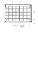
- FIG. 2 is an example of a tray member constituting the tray member for heat treatment shown in FIG. 1.
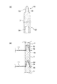
- FIG. 2 shows two examples of a component receiver constituting the tray member for heat treatment shown in FIG. 1.
- FIG. 3 is a diagram showing a form in which the tray members shown in FIG. 2 are stacked to form a multi-stage structure.
- FIG. 3 is a plan view of the tray member shown in FIG. 2. It is sectional drawing which shows an example which forms a multistage structure by stacking tray members.
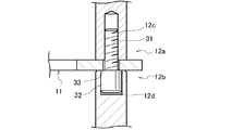
- FIG. 7 is a detailed sectional view of the connecting means having a multilayer structure shown in FIG. 6.
- FIG. 13 is a cross-sectional view illustrating another example of a multi-tiered structure in which tray members are stacked.
- FIG. 9 is a detailed sectional view of the connecting means having a multilayer structure shown in FIG. 8.
- FIG. 9 is a detailed sectional view of a connecting member used in the multilayer structure shown in FIG. 8.
- FIG. 12 is a perspective view illustrating an example of a tray on which the component receiver of FIG. 11 is placed.
- 13 is a perspective view showing a tray member for heat treatment in which the component receiver of FIG. 11 is placed on the tray of FIG. It is a perspective view which shows the laminated structure for heat treatment which laminated
- FIG. 17 is a perspective view showing an example of a tray on which the component receiver of FIG. 15 and the component receiver of FIG. 16 are placed.
- FIG. 18 is a perspective view showing a tray member for heat treatment in which the component receiver of FIG. 15 and the component receiver of FIG. 16 are placed on the tray of FIG. 17. It is a perspective view which shows the laminated structure for heat treatment which laminated
- FIG. 20 is a perspective view showing an example of a base member used in the heat treatment laminated structure of FIGS. 18 and 19. It is a perspective view which shows an example of the tray member in which the base and the support
- tray member for heat treatment and the laminated structure for heat treatment according to the present invention will be described with reference to the drawings. Note that the present invention is not limited to the embodiments described below.
- the heat treatment tray member 10 includes a composite member (hybrid member) including a tray 1 and a plurality of component receivers 2 removably mounted on the tray 1.
- This is a member that is repeatedly put into the heat treatment furnace together with the component to be heat treated.
- the tray 1 has a base 11 having a plurality of mounting portions 13 on which the component receiver 2 can be mounted at a predetermined position.
- the base 11 is made of a carbon composite material
- the component receiver 2 is made of a steel material or a Ni alloy material. Have been.
- the tray 1 is not an integral structure with the component receiver 2 as in the conventional example shown in FIG. 22, but is a separate member, so that the structure of the base 11 can be simplified. Can be. Further, the number of man-hours can be reduced as compared with the related art, and the manufacturing cost can be reduced.
- the base 11 constituting the tray 1 as a separate member from the component receiver 2 is made of a carbon composite material having heat resistance and resistant to thermal deformation, the tray 1 is repeatedly put into the heat treatment furnace for a long time. Even if it does, deformation, cracking, etc. hardly occur, so that it can be used repeatedly for a long time.
- the component receiver 2 which is a member separate from the tray 1, can be removably mounted on the plurality of mounting portions 13 on the tray 1, so that the component receiver 2 does not have a complicated shape or is not easily deformed by heat treatment for a long period of time. Can be exchanged for other spare parts immediately.
- the component receiver 2 made of a separate member is manufactured by the lost wax method, it is possible to obtain a low-cost and high-accuracy component.
- (Type) can be heat-treated in large numbers at once.
- the tray 1 is provided separately from the component receiver 2 and has at least a base 11.
- the base 11 is formed of a carbon composite material.
- the base 11 is a member having a plurality of mounting portions 13 on which a component receiver 2 described later can be mounted at a predetermined position.
- the tray 1 is provided with a corner support 12 and a center support 17 as necessary.
- the corner supports 12 and the center supports 17 are respectively provided at the corners 15 and the center or near the center of the tray 1.
- the corner support 12 and the center support 17 are also desirably formed of a carbon composite material. By doing so, the structure of the tray can be simplified.
- the entire tray is made of a carbon composite material that has heat resistance and is not easily thermally deformed. Therefore, even when a plurality of trays to be used repeatedly are repeatedly put into the heat treatment furnace for a long period of time, deformation and cracking are unlikely to occur, so that the trays can be used repeatedly for a long period of time.
- the corner support 12 and the center support 17 provided on the tray 1 may be formed of a steel material or a Ni alloy material. Steel materials or Ni alloy materials are inferior in heat resistance and heat deformability as compared with carbon composite materials, but are less expensive than carbon composite materials, so they may be replaced when they cannot be used due to thermal deformation or the like. .
- a side support (not shown) may be provided on the periphery of the tray. The side support is also preferably formed of the same material as the corner support 12 and the like.
- the heat treatment tray member 10 according to the first embodiment will be described by taking, as an example, a tray 1 having a base 11, a corner support 12, and a center support 17.
- Carbon composite material Carbon composite materials have higher heat resistance than metal materials and are less likely to thermally expand or deform.
- the base 11, the corner support 12, and the center support 17 By fabricating the base 11, the corner support 12, and the center support 17 from the carbon composite material, even when the tray 1 is repeatedly put into the heat treatment furnace for a long time, deformation, cracks, etc. are unlikely to occur, and the tray 1 is repeatedly used for a long time. Can be used.
- the carbon composite material has heat resistance enough to be used even at about 2200 ° C. Therefore, unlike a carburizing treatment or a nitriding treatment of a component to be heat-treated, there is no adverse effect due to thermal deformation due to a heat treatment temperature of about 950 ° C. to about 1200 ° C.
- the structure of the tray 1 (the base 11, the corner support 12, the center support 17) be made as simple as possible and then made of the carbon composite material. . Trays made of carbon composite material can be used for a long time. As a result, in terms of total cost, even if the tray is made of an expensive carbon composite material, the cost can be significantly reduced.
- the carbon composite material can be used as various materials.
- a high-strength, high-elasticity carbon material preferably reinforced with carbon fibers is preferred.
- those obtained by combining carbon fibers as a reinforcing fiber with a carbon matrix such as graphite can be preferably mentioned.
- the carbon fibers fibers having a longer fiber length than fibers having a shorter length are preferable, and those having a regular arrangement in the vertical and horizontal directions than those randomly arranged in the matrix without any direction are preferable.
- the composite of the carbon fibers in the matrix in this manner can be preferably used as a high tensile strength and high elasticity carbon composite material for the tray 1 (base 11, corner support 12, center support 17) of the present invention.
- the bending strength is about 140 to 160 MPa
- the tensile strength is about 250 MPa
- the bulk specific gravity is about 1.6 g / cm 3
- the compression strength is about 90 MPa.
- the flexural modulus is about 60 GPa
- the tensile modulus is about 80 GPa.
- the thermal expansion coefficient is about 0.2 to 0.4 (//) ⁇ 10 ⁇ 6 / K and about 5 to 9 ( ⁇ ) ⁇ 10 ⁇ 6 / K
- the thermal conductivity is about 27 (//).
- the tray 1 When the tray 1 includes the base 11, the corner support 12, and the center support 17, they may be made of the same carbon composite material or may be made of different carbon composite materials. Good. Whether they are the same or different can be arbitrarily selected in consideration of ease of production, material cost, strength required for each, and the like.
- carbon composite material for example, SGL Carbon Japan Co., Ltd.'s Sigrabond series, Nippon Carbon Co., Ltd.'s CCM190 series, etc. can be arbitrarily obtained, and these can be arbitrarily selected and used. Further, a material in which carbon composite material is impregnated with Si can be arbitrarily selected and used. These carbon composite materials are also marketed as bolts and nuts, and these can be used or processed. In addition, the processing method of these carbon composite materials is not particularly limited, but can be processed into a predetermined structural shape by general processing means such as cutting, grinding, and water jet cutting.
- the base portion 11 is a member having a plurality of mounting portions 13 capable of mounting the component receiver 2 at a predetermined position as shown in FIGS.
- the base 11 is provided with a mounting portion 13, a column mounting portion (mounting hole) 16 provided at the corner 15, and a column mounting portion (mounting hole) 18 provided at or near the center.
- the mounting portion 13 is a portion where the component receiver 2 is easily mounted.
- the shape of the mounting portion 13 is not particularly limited, it is preferable that the mounting portion 13 has a frame structure including a frame (eg, 13a, 13b) and a space 14 surrounded by the frame (eg, 13a, 13b).
- the shape of the frame structure is preferably selected from a circle, an ellipse, a triangle, a square (a rectangle such as a square and a rectangle), a honeycomb (a hexagon), and similar shapes.
- a rectangular frame-shaped mounting portion 13 composed of a vertical frame 13a and a horizontal frame 13b is shown as a preferable example that can be easily processed at low cost. Since the mounting portion 13 for mounting the component receiver 2 has a simple frame structure, the component receiver 2 can be easily mounted. As a result, the component receiver 2 can be mounted on the base 11 which has heat resistance and is not easily thermally deformed. Furthermore, since the structure is extremely simple as compared with the conventional example shown in FIG. 22, the carbon composite material can be easily processed and can be manufactured at low cost. Further, the component to be heat-treated can be heat-treated without worrying about deformation or cracking of the tray as in the conventional case.
- the base 11 may be obtained by molding the mounting part 13 or by processing the mounting part 13 after obtaining a board.
- the thickness of the base portion 11 and the size and shape of the mounting portion 13 can be arbitrarily designed depending on the use form, heat treatment conditions, the structure form of the component receiver 2, and the like. Also, in the actual heat treatment step of the parts, if various bases 11 having different sizes and shapes of the mounting parts 13 are prepared and the bases 11 are made into a series, various bases 11 and parts receivers 2 are exchanged to thereby obtain various kinds of parts. Heat treated parts can be heat treated.
- a column mounting portion (mounting hole) 16 for connecting the corner column 12 to the base 11 is provided.
- a support mounting portion (mounting hole) 18 for connecting the center support 17 to the base 11 is provided. Is provided.
- the corner support 12 is a member provided at the corner 15 of the base 11 for stacking a plurality of trays 1.
- the corner support 12 is usually made of a carbon composite material having a round bar shape or a square bar shape, but may be a steel material or a Ni alloy material.
- an engaging portion 12 c for example, a screw
- a connecting member 31 for example, a connecting screw
- An engaging portion 12d (e.g., an engagement portion) that engages (e.g., inserts and mounts) with another connection member 31 (e.g., a screw head) and is connected to another tray 1 stacked on the upper stage is provided on the support upper portion 12b of the corner support 12. Insertion hole).
- the corner support 12 can be connected to the base 11 by the connecting member 31 and also to another tray 1.
- the connection member 31 is preferably a connection screw, but any other member may be used as long as it has a similar function.
- the corner support 12 is also formed of a carbon composite material, similarly to the base 11. Therefore, it is not necessary to adopt a rigid structure as shown in the conventional example of FIG. 22, and a simple columnar member or the like is sufficient.
- the corner support 12 can be arbitrarily selected and used which can withstand the weight on which the trays 1 are stacked.
- the corner support 12 can be obtained by molding, but various sizes can be obtained from the market.
- connection member 31 when the connection member 31 is a screw (referred to as a connection screw), the engagement portion 12 c of the support lower portion 12 a is screwed with the connection screw 31 and connected to the base 11. It can be. Further, the engaging portion 12d of the upper column portion 12b can be an insertion hole for inserting the head of the connection screw 31 connected to another tray.
- the shape of the head is not particularly limited, the shape of the head may be any shape as long as the head does not rotate and the hole shape of the engaging portion 12d. And a hexagon or the like excluding.).
- the dimensions and shape of the screw holes and the insertion holes can be arbitrarily designed according to the screw pitch, screw length, head shape, and the like of the connection screw 31 to be used, and are not particularly limited.
- the engaging portions 12c and 12d can be formed according to the shape and function of the connecting member 31.
- the center support pillars 17 are provided at or near the center of the base 11 in one or two or more numbers as needed. By providing the center support 17, the stacked trays 1 can be supported more stably.
- the center support 17 is made of a carbon composite material in the shape of a round bar or a square bar, like the corner support 12 described above, but may be a steel material or a Ni alloy material.
- the number and positions of the center supports 17 are not particularly limited, but may be any number and positions that can stably support the stacked trays 1, and may be two as shown in FIG. 1 or the like, or three or more ( (Not shown). Further, they may be provided in an arrangement as shown in FIG. 1, or may be provided in an arrangement as shown in FIGS. 2, 4, and 5.
- the connecting member of the center support 17 be the same as the connecting member 31 of the corner support 12. By doing so, the center support 17 can be shared with the corner support 12.
- the base 11 is provided with a column mounting portion (mounting hole) 18 for connecting the center column 17. Note that the other parts are the same as those of the corner support 12, so that the description thereof is omitted here.
- connection means As connecting means for stacking the trays 1 in multiple stages, the first connecting means in FIGS. 6 and 7 can be mentioned.
- the connection by the first connecting means is performed by the support 3 (the corner support 12 and the center support 17; the same applies hereinafter) and the connection member 31.
- the lower portion 12 a of the column 3 has an engaging portion 12 c (engaging hole) that engages with the upper portion 12 b of another column 3 via the connecting member 31.
- the upper portion 12b of the column 3 has an engaging portion 12d (insertion hole) that engages with the lower portion 12a of another column 3 via another connecting member 31.
- the connecting member 31 is engaged with the upper engaging portion 33 (screw portion) engaging with the engaging portion 12c (screw hole) of the lower column 12a and the other upper column 12b of the lower column. And a lower engaging portion 32 (column portion) that engages with the portion 12d (insertion hole).
- the tray 1 is sandwiched between the column 3 and the connecting member 31 while being placed on the shoulder of the lower engaging portion 32 (column portion) of the connecting member 31.
- the first connecting means has the trays 1 stacked using a screw member as the connecting member 31, and is different from a second connecting means which does not use a connecting screw described later.
- a screw member (also referred to as the connecting screw 31) made of a carbon composite material is preferably used.
- the connecting member 31 (connecting screw) engages (screws) with the engaging portion 12c (screw hole) of the lower column portion 12a of the corner column 12, and acts to connect the corner column 12 and the tray 1. I do. Further, the connecting member 31 (connecting screw) engages (inserts) with the engaging portion 12d (insertion hole) of the column upper portion 12b of the other corner column 12 arranged at the lower stage, and the other corner column 12 and the lower column are connected. In order to engage (insert) with the tray 1. As shown in FIG. 6, the center support 17 can be connected to the upper and lower center supports 17 by the same connecting member 31.
- the connecting member 31 engages with the upper and lower columns 3 to connect them.
- the base portion 11 is provided with a mounting hole formed by a corner post mounting portion 16 and a mounting hole formed by a center post mounting portion 18.
- a connecting member 31 (connecting screw) is inserted into the mounting hole from below, and screwed into an engaging portion (screw hole) 12c of the lower column portion 12a.
- the connecting member 31, the support 3, and the base 11 sandwiched therebetween are integrated as the tray member 10.
- the lower engaging portion (column portion) 32 of the integrated tray member 10 is inserted into the engaging portion (insertion hole) 12 d of the column 3 of another tray member 10.
- the tray members 10 are stacked by the first connecting means to form a stacked structure for heat treatment.
- the structure of the connecting member 31 is not particularly limited, but can be arbitrarily designed depending on the usage, heat treatment conditions, structure of the corner support 12, and the like.
- a screw-shaped connecting member 31 connecting screw
- the screw pitch, the screw length, the head shape, and the like can be arbitrarily designed in the same manner as a general metal screw.
- relatively simple hexagon bolts and square bolts can be preferably used.
- a member other than the screw-shaped connecting member 31 may be adopted.
- the connecting member 31 when the connecting member 31 is a screw, it is sufficient that the connecting member 31 has a head shape such that the head does not rotate and a hole shape of the engaging portion 12d. Is preferably the same shape (however, a square or hexagon excluding a circular shape).
- the connecting member 31 may be a carbon composite material, a steel material or a Ni alloy material.
- connection by the second connecting means is performed by engaging the column 3 except for the connecting member 41 used at the lowermost stage.
- the lower portion 54 of the column 3 has a lower engaging portion 52 that directly engages with the upper portion 53 of another column and connects to the base 11 without using a connecting member.
- the upper portion 53 of the column 3 has an upper engaging portion 51 that directly engages with the lower portion 54 of the other column 3 without using a connecting member and connects to another tray 1 stacked on the upper stage.
- the second connecting means uses the column 3 having the upper engaging portion 51 provided in the column upper portion 53 and the lower engaging portion 52 provided in the column lower portion 54 as a connecting member.
- the tray 1 is sandwiched between the upper and lower columns 3 while being placed on the shoulder 55 of the lower engaging portion 52 of the column 3.
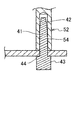
- FIG. 10 shows a connecting member 41 located at the bottom of the tray member 10 for heat treatment.
- the upper engaging portion 51 provided on the upper portion of the column 3 is a protrusion
- the lower engaging portion 52 provided on the lower portion 54 of the column 3 is an engaging hole.
- the projection and the engagement hole are formed in a predetermined size, and act so that the projection of the pillar 3 located below is inserted into and connected to the engagement hole of the pillar 3 located above.
- the base 11 of the tray 1 is sandwiched between the projection and the engagement hole.
- the base 11 rests on a lower column shoulder (base receiving portion) 55 and is pressed by an upper column lower portion 54.
- the tray member 10 is laminated by the second connecting means, and becomes a laminated structure for heat treatment.
- FIG. 10 shows an example of the connecting member 41 located at the lowest stage.
- the connecting member 41 has a projection which extends upward in the same manner as the above-described upper engaging portion 42 of the column 3 and is inserted into the engaging hole of the column lower portion 54, and a head 43 which has a shoulder portion 44 located below. It is composed of Also in the lowermost connecting member 41, the projection and the head 43 are formed in a predetermined size, and the base 11 of the tray 1 is sandwiched between the projection and the head 43. The base portion 11 rests on a lower shoulder portion (base receiving portion) 44 and is pressed by an upper column lower portion 54. Therefore, in the second connecting means shown in FIGS.
- the lower engaging portion 52 for connecting the base 11 of the first stage and the lower portion 54 of the column 3 is connected by the connecting member 41,
- An engaging portion connected to another tray 1 stacked on the first column 3 is connected to an upper engaging portion 51 of the first column 3 and a lower engaging portion 52 of the second column 3.
- the structure of the support 3 and the connecting member 41 constituting the second connecting means is not particularly limited, but can be arbitrarily designed depending on the use form, heat treatment conditions, the structure of the corner support 12 and the center support 17 and the like.
- the clearance between the projection and the engagement hole is appropriately designed so that the backlash does not increase.
- the protrusion of the upper column 53 may be a male screw
- the engaging hole of the lower column 54 may be a female screw. In the case of a screw structure, these screws can be arbitrarily designed with a screw pitch, a screw length, a head shape, and the like, like a general metal screw.
- the connecting member 41 may be a carbon composite material, a steel material or a Ni alloy material.
- the lower portion of the column 3 has a lower engaging portion that engages with the upper portion of another column 3 via a connecting member (for example, a connecting screw), and the upper portion of the column 3 is It may be configured to have an upper engaging portion (engaging protrusion) that directly engages with an engaging hole at a lower portion of another pillar without going through.
- a connecting member for example, a connecting screw
- the connecting screw is used similarly to the second connecting means.
- the lower part of the column 3 has a lower engaging portion (engaging hole) which directly engages with the upper engaging projection of the other column 3 without using a connecting member.
- the upper portion may be configured to have an upper engaging portion that engages with a lower portion of another pillar 3 via another connecting member.
- “without the intermediary of the connecting member” refers to a case where the column 3 having the upper engaging portion 51 and the lower engaging portion 52 is employed, as in the second connecting means.
- "" Means a case where a connecting screw is employed, as in the case of the first connecting means.
- the first to fourth connecting means can be mentioned as the connecting means.
- these connecting means when the connecting members 31 and 41 connected to the first-stage support 3 are made of a carbon composite material, a sheet of a steel material or a Ni alloy material is disposed thereunder, or a steel material or a Ni alloy material is It is preferable to put it on the bread. By doing so, it is possible to prevent abrasion of the connecting members 31 and 41 that occurs when carrying in / out the heat treatment furnace. Further, even when the bottom surface of the base 11 directly contacts the floor surface even when the first-stage connecting members 31 and 41 are engaged, when the sheet is placed or placed on a pan and carried into and out of the heat treatment furnace. Of the connecting members 31 and 41 and the bottom surface of the base can be prevented.
- the component receiver 2 includes a pedestal 21 detachably contacting the tray 1, a locking portion 22 provided on the pedestal 21 to hold the pedestal 21 on the tray 1, and extends on the pedestal 21. Alternatively, it has a component receiving portion 23 on the pedestal 21.
- the component receiver 2 has the locking portion 22 provided on the pedestal 21 that comes into contact with the tray 1, so that the detachable component receiver 2 can be held as a separate member on each mounting portion of the tray 1.
- the component receiver 2 can be prepared as a spare, and even when heat-treated components of other shapes are simultaneously heat-treated, it is possible to simultaneously mount a plurality of types of component receivers 2 mounted on the tray 1.
- the structure of the component receiver 2 having such a function and effect is not limited to the shapes shown in FIGS.
- the component receiver 2 illustrated in FIGS. 3A and 3B has a structure including a frame-shaped receiving portion 24 and a support portion 25.
- the component receivers 2 are detachably mounted on the trays 1 for mounting the components to be heat-treated and heat-treating them in a heat treatment furnace.
- the component receiver 2 (2A, 2B) may be formed in a complicated shape, and is desirably formed with high dimensional accuracy.
- the reason why the component receiver 2 is formed with high dimensional accuracy is that carburizing tends to be insufficient at a portion where the component receiver 2 and the component to be heat-treated come into contact with each other. This is because there are many cases where parts touch with each other or parts may touch each other, and the required quality regarding the carburizing property of the parts after the heat treatment may not be satisfied.
- the pitch and gap between the component receivers 2 need not be unnecessarily widened, but the mounting density of the component receivers 2 must be increased (increased) in order to efficiently heat-treat the component to be heat-treated. is there. Therefore, it is desirable that the pitch and gap between the component receivers 2 be narrow, and therefore, it is desirable that the component receivers 2 be manufactured with high dimensional accuracy.
- the component receiver 2 is particularly preferably manufactured by the lost wax method described later, and is excellent in cost. Since the lost wax method can be manufactured accurately even at a low cost even in a complicated shape, for example, in the cylindrical component receiver 2A shown in FIG. 3A, the components to be heat-treated include the circular frame-shaped inner surface 26a and the support portion inner peripheral surface 25a. It is desirable that the design is made with high dimensional accuracy so as not to contact the surface. For this purpose, the component to be heat-treated may be mounted on the mounting surface 24a shown in FIG. 3A, and may be fixed in position so as to prevent rattling on the optionally provided side surface 24b.
- the component receiver 2 manufactured by the lost wax method can heat-treat one or many types of heat-treated components at a time even if it has a complicated shape. Since the dimensional accuracy of the mounting surface 24a and the side surface 24b can be increased, the contact between the component to be heat-treated and the component receiver 2A can be avoided, and the carburizing process can be performed uniformly, and the high-quality carburizing process can be performed. Parts can be manufactured at low cost.
- the heat-treated component is inclined due to the inclination or vibration during the transfer of the tray 1. It will rattle and come into contact with the inner surface 26a of the circular frame and the inner peripheral surface 25a of the support portion. Such contact may result in insufficient carburization or the like, and may not satisfy the required quality of carburizing property of the heat-treated part.
- the contact between the heat-treated component and the component receiver 2A can be avoided, the carburizing process can be performed uniformly, and a high-quality carburized component can be manufactured at low cost.
- the component receiver is formed of a grid-like C / C composite as in Patent Literature 4.
- the present invention removably mounts the component receiver 2 as a separate member on a tray made of a carbon composite material that does not easily undergo thermal deformation or distortion, as shown in FIG. Even when the component receiver 2B in the form is mounted on the tray at a particularly narrow pitch, the component tray 2B does not tilt because the tray 1 does not bend or warp.
- the receiver 2 can be manufactured accurately by the lost wax method. As a result, the dimensional accuracy of the rod-shaped support 25 of the component receiver 2B can be increased, and the dimensional difference between the outer peripheral surface 25b of the rod-shaped support 25 and the inner diameter of the circular heat-treated component (gear or the like) can be appropriately controlled.
- the heat-treated component having a circular shape (such as a gear) does not protrude from the mounting surface 24c or the pedestal 21, so that it is possible to prevent adjacent heat-treated components from touching each other.
- the present invention enables a sufficient and uniform carburizing treatment of a part to be heat-treated, and can satisfy required quality as a part.
- the method of manufacturing the component receiver 2 is not particularly limited, but it is particularly desirable to employ the lost wax method because machining such as cutting increases the cost.
- machining such as cutting increases the cost.
- the lost wax method complicated and high-precision structural parts can be efficiently manufactured. Since the component receiver 2 manufactured by the lost wax method can be detachably mounted on the tray 1 as a separate member from the tray 1, even if the component receiver 2 does not have a complicated shape or is not easily deformed for a long period of time by heat treatment, other components can be used immediately. Can be exchanged for spare parts.
- a prototype is made with wax, the surroundings of the prototype are covered with casting sand or plaster, and the wax is melted and removed by heating, and the molten steel material is poured into the resulting cavity, and the prototype is cast. It is a method of obtaining a casting having the same shape as the above.
- the material of the component receiver 2 is not particularly limited as long as it is a steel material or a Ni alloy, but is preferably a steel material or a Ni alloy that can be preferably manufactured by a lost wax method.
- Specific examples include nickel-containing steel materials such as austenitic stainless steel and heat-resistant cast steel, and high-Ni alloys such as Inconel. Since these steel materials or Ni alloys are excellent in high-temperature strength and high-temperature oxidation resistance, they can be preferably used as members repeatedly put into a heat treatment furnace. From the viewpoint of heat resistance and prevention of thermal deformation, a steel material or a Ni alloy containing various metal materials may be used, or the component receiver 2 after processing may be subjected to a hardening treatment or a surface modification treatment. Is also good.
- the component receiver 2 includes a pedestal 21 detachably contacting the tray 1, a locking portion 22 provided on the pedestal 21 and holding the pedestal 21 on the tray 1. And a component receiving portion 23 extending on the pedestal 21.
- the locking portion 22 is provided on the pedestal 21 that comes into contact with the tray 1, and the locking portion 22 acts to hold the detachable component receiver 2 at a predetermined position on the tray 1. I do. Even when such a component receiver 2 is prepared as a spare or a heat-treated component having another shape is simultaneously heat-treated, it is possible to simultaneously mount a plurality of types of component receivers 2 to be mounted on the tray 1.
- the pedestal 21 is detachably contacted on the base 11 of the tray 1 and acts so as to be placed thereon.
- the shape is not particularly limited. For example, as shown in FIGS. 3 and 5, when the base 11 of the tray 1 is a rectangular mounting portion 13, the shape of the pedestal is circular, and each side of the square of the mounting portion 13 is formed. It is preferable that the pedestal 21 is formed in such a size that the circular pedestal 21 is placed on the pedestal.
- the locking portion 22 is provided on the pedestal 21 and functions to hold the pedestal 21 on the tray 1.
- the shape is not particularly limited, for example, as shown in FIGS. 3 and 5, it is preferable that three or four protrusions are provided below the circular pedestal 21.
- the component receiver 2 mounted on the mounting portion 13 of the base 11 can be held without being displaced from the position.
- the shape, number, position, and the like of the protrusions can be arbitrarily designed according to the shape, dimensions, and the like of the mounting portion 13 and the like.
- the component receiving portion 23 extends on the pedestal 21 and acts to place the component to be heat-treated, and has at least a frame-shaped receiving portion 24 and a support portion 25 as shown in FIGS. It is configured.
- the shape is not particularly limited, but may be, for example, any of the shapes illustrated in FIGS.
- the component receiver 2 since the component receiver 2 is formed separately from the tray 1, it can be formed by a lost wax method or the like even in a complicated shape, which is convenient. And, even if the deformation is accumulated or the cracks caused by the use for a long period of time are increased and the replacement is required, only the component receiver 2 to be replaced needs to be replaced, which is more costly than replacing the entire integrated structure. Can be greatly reduced.
- the frame-shaped receiving portion 24 is a frame-shaped structure portion on which the component to be heat-treated is mounted, and is provided, for example, so as to bridge the circular pedestal 21, and has an upper surface mounted thereon as shown in FIGS.
- the placement surfaces 24a and 24c are provided.
- the shape is not particularly limited, but is preferably a cross-linking form extending from four or three places of the circular pedestal 21 toward the center as shown in FIG.
- the side surface 24b in FIG. 3A restrains the heat-treated component (for example, a columnar heat-treated component) mounted on the mounting surface 24a from four sides so as to prevent rattling. Acts to fix the position.
- the support portion 25 is provided to extend upward from the frame-shaped receiving portion 24, for example.
- the column 25 in FIG. 3A is configured by four columns extending upward from four places of the circular pedestal 21, and the column 25 in FIG. It is composed of a single column extending upward from the center of the frame-shaped receiving portion 24 extending from the circular pedestal 21.
- 3B is a column 25 having a rod shape or a cross section extending radially.
- FIG. A column 25 having a rod-shaped or radially extending cross-section is inserted into the round hole, and acts on the mounting surface 24c of the component receiver 2B.
- the outer frame 26 acts to support the heat-treated component on the mounting surface 24a, even if the component to be heat-treated falls down, as in the structure shown in FIG.
- the shape is not particularly limited, but is preferably a circle as shown in FIG.
- the heat treatment tray member 10 can be used for a long period of time by suppressing the occurrence of deformation and cracking even when the components are placed in a heat treatment furnace repeatedly for heat treatment of the components. it can.
- the trays 1 can be stacked in multiple stages, and a large number of single- or multiple-form heat-treated components can be placed on the component receiver 2 and heat-treated at the same time.
- the heat treatment tray member 10 of the first embodiment can be configured.
- the trays 1 connected by the connection means are stacked in multiple stages to form a heat treatment laminated structure.
- a detachable component receiver 2 is placed on each tray 1, and components can be placed on the component receiver 2 and put into a heat treatment furnace.
- Uniform carburizing treatment can be performed.
- the tray member 10 for heat treatment according to the second embodiment is configured such that the component receiver 2 and the tray 1 are combined to form tray members 10A and 10B. This is different from the tray member for heat treatment of the first embodiment in which is used as a connecting means.
- the tray members 10A and 10B are laminated in multiple stages to form laminated structures for heat treatment 60A and 60B shown in FIGS.
- the heat treatment laminated structures 60A and 60B by stacking the tray members 10A in multiple stages, a plurality of trays 1 on which a large number of components to be heat treated can be placed can be stacked.
- the connecting means for combining the component receiver 2 and the tray 1 will be described as fifth and sixth connecting means.
- FIG. 11 is an example of the component receiver 2C
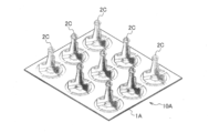
- FIG. 12 is an example of a tray 1A on which the component receiver 2C is mounted
- FIG. 13 is a heat treatment tray member 10A on which the component receiver 2C is mounted on the tray 1A.
- FIG. 14 shows a heat treatment laminated structure 60A in which heat treatment tray members 10A are laminated.
- the fifth connecting means can configure the tray member 10A by combining the component receiver 2C and the tray 1A without using a support.
- the component receiver 2C acts as a connecting member, and the tray 1A is sandwiched between the component receivers 2C arranged vertically to form a tray member 10A.
- the same reference numerals are used for the parts receivers constituting the tray members 10A of the upper and lower tiers.
- those in the lower row are represented as “parts receiver 2C ′′”, “tray 1A ′′”, etc.
- the component receiver 2C includes a pedestal 21 detachably contacting the tray 1A, a locking portion 22 provided on the pedestal 21 and holding the pedestal 21 on the tray 1. And a component receiving portion 23 extending on the pedestal 21.
- the locking portion 22 acts to hold the detachable component receiver 2C at a predetermined position on the tray 1A. I do.
- a plurality of types of component receivers 2C mounted on the tray 1A can be simultaneously mounted.
- the component receiver 2C is formed separately from the tray 1, and can be formed by a lost wax method or the like, which is convenient.
- the pedestal 21 comes into contact with the tray 1A in a detachable manner, and acts so as to be placed thereon.
- the shape is not particularly limited, but is preferably a circular shape, for example, as shown in FIG.
- the locking portion 22 is provided on the pedestal 21 and functions to hold the pedestal 21 on the tray 1.
- the shape is not particularly limited, for example, as shown in FIG. 11, it is preferable that the protrusions extend radially in three directions from the circular pedestal 21.
- the component receiver 2C mounted on the mounting portion 13 of the tray 1A can be held without being displaced from the position.
- the shape, number, position, and the like of the protrusions can be arbitrarily designed according to the shape, dimensions, and the like of the mounting portion 13 and the like.
- the component receiving portion 23 extends on the pedestal 21 and acts to mount the component to be heat-treated, and is configured to have at least a mounting surface 24c and a support portion 25 as shown in FIG.
- the shape is not particularly limited, but may be, for example, any shape illustrated in FIG.
- the mounting surface 24c is a portion on which the component to be heat-treated is mounted, and its shape is not particularly limited. However, it is preferable that the mounting surface 24c is provided at a position extending radially in three directions from the circular pedestal 21 as shown in FIG.
- the support 25 is provided to extend upward from the pedestal 21.
- the shape thereof is not particularly limited, but the strut portion 25 in FIG. 11 is configured by a rod-shaped strut extending upward from four places of the circular pedestal 21.
- the cross section of the column has a shape having side surfaces 25b extending radially in three directions.
- a circular heat-treated component (gear or the like) having a round hole formed in the center is preferably mounted on the component receiving portion 23.
- the support portion 25 is inserted into the round hole, and the mounting surface 24c of the component receiver 2B is mounted. Put on top.
- the component receiver 2C includes an upper engaging portion (projection) 25c and a lower engaging portion (hole) 21d.
- the upper engaging portion (projection) 25c engages with a lower engaging portion (hole) 21d 'of another component receiver 2C' provided in the upper tray 1A ', and the component receiver 2C and the upper tray 1A' Concatenate.
- the upper engaging portion (projection) 25c has a shoulder 25e for mounting and supporting another upper tray 1A '.
- the height and shape of the projection serving as the upper engaging portion 25c are not particularly limited, as shown in FIG. 11, the size may be equal to or less than the depth size of the hole serving as the lower engaging portion 21d. It is preferable that the tapered shape be slightly narrower as it goes. As shown in FIG.
- the shoulder 25e constitutes a part of the upper engaging portion (projection) 25c, and when the upper engaging portion (projection) 25c is inserted into the through hole 13c of the tray 1A, It is a portion that acts to support and support 1A. Therefore, the shoulder 25e may be a circular flange as shown in FIG.
- the lower engaging portion (hole) 21d is engaged with the upper engaging portion (projection) 21d "of the other component receiver 2C" provided in the lower tray 1A ", and the component receiver 2C and the lower tray 1A” Concatenate.
- the lower engaging portion (hole portion) 21d is a recessed hole, and its depth and size are not particularly limited. However, as shown in FIG. 11, the protrusion size of the upper engaging portion 25c is equal to or larger than that. It is preferable that the size is a size, and it is preferable that the shape be a tapered hole shape that becomes slightly thinner as it goes deeper into the hole.
- the dimensional accuracy of the component receiver 2C is high, and the mounting density can be increased. As a result, the adjacent heat-treated components do not come into contact with each other, and the carburizing failure at the contact location does not occur.
- the part to be heat-treated may come into contact with the mounting surface 24c and the side surface 25b, but it is assumed that the contact location is not a location that affects the carburizing quality.
- the tray 1A is provided separately from the component receiver 2C and is made of a carbon composite material.
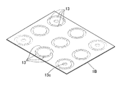
- the tray 1A is a member having a plurality of mounting portions 13 on which the component receiver 2C can be mounted at a predetermined position. All mounting portions 13 are provided with through holes 13c.
- the through-hole 13c is positioned by engaging the projection 25c of the lower component receiver 2C ′′ with the hole 21d of the component receiver 2C.
- the tray 1A in the tray 1A according to the first embodiment is positioned. Therefore, there is no mounting hole for the corner support and the center support provided in the tray 1. Therefore, the stacking of the tray 1 is not performed using the corner support and the center support, but the component receiver 2C and the tray 1A are provided in all the mounting portions 13. The combination is performed by engaging with the provided through hole 13c.
- the component receiver 2C mounted on the mounting portion 13 of the tray 1A is positioned and held so as not to shift from the position.
- the shape of the mounting portion 13 and the size and position of the through hole 13c can be arbitrarily designed according to the shape and size of the component receiver 2C.
- the heat receiving tray member 10A shown in FIG. 13 is formed by placing the component receiver 2C on the tray 1A, and the heat processing laminated member 60A shown in FIG. 14 is formed by stacking the heat processing tray members 10A.
- the heat treatment laminated structure 60A is obtained by stacking the heat treatment tray members 10A.
- a base member 4 described later is used as a lowermost member, and a heat treatment tray member 10A shown in FIG. 13 is placed thereon as a first-stage tray member.
- the second stage heat treatment tray member 10A is placed, and the third stage and subsequent stages are further placed.
- a laminated structure for heat treatment 60A in which the tray members 10A are laminated in multiple stages is obtained.
- the tray 13 may be sequentially stacked, or the tray 1A may be placed on the base member 4, and the component receiver 2C may be placed on the mounting portion 13 of the tray 1A.
- the trays 1A ' may be placed side by side, then the trays 1A' may be placed, and the component receivers 2C 'may be placed side by side on the mounting portion 13' of the tray 1A '.
- ⁇ Base member> In the heat treatment laminated structure 60A, a plurality of heat treatment tray members 10A are stacked and repeatedly put into the heat treatment furnace together with the parts to be heat treated.
- the base member 4 shown in FIG. 20 may be preferably employed as the first stage heat treatment tray member.
- the base member 4 is preferably made of a steel material or a Ni alloy material.
- the second or higher heat treatment tray member is the heat treatment tray member 10A.
- the base member 4 can prevent the lower surface of the heat treatment tray member 10A from being worn when the substrate is carried into and out of the heat treatment furnace.
- the base member 4 has a reinforcing hole 4a and a space 4b.
- the reinforcing hole 4a is provided so as to increase the rigidity and the like of the entire base member by providing a circular hole at the intersection of the frame.
- the space 4b is arbitrarily provided as necessary to reduce the weight.
- the base member 4 is the same as the one described above as “pan” in the description section of the connecting means.
- the heat treatment tray member 10 according to the first embodiment of the present invention may be stacked on the base member 4.
- ⁇ Sixth connection means> 15 and 16 show examples of the component receivers 2D and 2E.
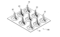
- FIG. 17 shows an example of the tray 1B on which the component receivers 2D and 2E are placed.
- FIG. 18 shows the component receivers 2D and 2E placed on the tray 1B.
- FIG. 19 shows a heat treatment laminated structure 60B in which the heat treatment tray members 10B are laminated.
- the sixth connecting means can configure the tray member 10B by combining the two types of component receivers 2D and 2E and the tray 1B.
- the component receivers 2D and 2E function as connecting members, and the tray 1B is sandwiched between the two types of component receivers 2D and 2E arranged vertically to form a tray member 10B.
- the “component receivers 2D and 2E” are used with the same reference numerals used for the component receivers constituting the tray members 10B of the upper and lower tiers.
- each of the component receivers 2 ⁇ / b> D and 2 ⁇ / b> E includes a pedestal 21 detachably contacting the tray 1 ⁇ / b> A, and a locking portion provided on the pedestal 21 and holding the pedestal 21 on the tray 1. 22 and a component receiving portion 23 extending on the pedestal 21. Since the pedestal 21, the locking portion 22, and the component receiving portion 23 have the same structure as the component receiving portion 2C described in the fifth connecting means, the description thereof will be omitted.
- the component receiver 2D shown in FIG. 15 includes only the shoulder 25e for mounting and holding the upper tray 1B 'without engaging with the lower engagement portion 21d' of the other component receiver 2D 'provided in the upper tray 1B'. It has a hole 21d at the bottom, which may be at the top and may or may not engage with the top of another component receiver 2D "provided in the lower tray 1B". That is, the protrusion 25c of the component receiver 2C shown in FIG. 11 is not provided on the upper part of the component receiver 2D, but only the shoulder 25e is provided. In the component receiver 2D, when the tray 1B 'is provided on the component receiver 2D, the shoulder 25e contacts the tray 1B' from below and acts to support the tray 1B '.
- the height from the lower end of the base 21 to the upper end of the shoulder 25e is preferably the same as the height pitch of the tray member 10B.
- the lower part of the component receiver 2D is provided with a hole 21d similar to the component receiver 2C shown in FIG. The form of this hole is the same as that of the component receiver 2C in FIG.
- the component receiver 2E shown in FIG. 16 has a projection 25c on the upper portion that engages with the lower engagement portion 21d ′ of the other component receiver 2E ′ provided in the upper tray 1B ′, and has another component provided in the lower tray 1B ′′.
- the lower part has a hole 21d that engages with the projection 25c ′′ of the component receiver 2E ′′. That is, the upper part of the component receiver 2E is not provided with the shoulder 25e of the component receiver 2C shown in FIG. In the component receiver 2E, when the tray 1B 'is provided on the component receiver 2E, the projection 25c passes through the through hole 13c' of the tray 1B ', and the component receiver 2E located on the upper stage.
- the protrusion 25c has the same form as that of the component receiver 2C shown in Fig. 11.
- the lower portion of the component receiver 2E is the same as the component receiver 2C shown in Fig. 11.
- Hole 21d It is.
- the form of the hole is the same as the parts receiving 2C in FIG.
- the tray member 10B shown in FIG. 18 is configured by combining two types of the component receiver 2D and the component receiver 2E, but the component receiver 2D and the component receiver 2E are replaced or a part of the structure is changed. Other component receivers may be used.
- the lower hole 21d may not be provided. More specifically, the upper tray 1B 'does not engage with the lower engaging portion 21d' of the other component receiver 2D ', and only the shoulder 25e for mounting and holding the upper tray 1B' is moved upward. And the hole 21d which does not need to be engaged with the upper part of another component receiver 2D "provided in the lower tray 1B" may not be provided in the lower part.
- the above-described component receiver 2E may not include the lower hole 21d.
- the upper tray 1B ' has another projection 2c' on the upper portion that engages with the lower engagement portion 21d 'of the other component receiver 2E' provided on the upper tray 1B ', and the other component receiver 2E "provided on the lower tray 1B". It is good also as a form which does not have the hole part 21d which engages with the projection 25c ′′ of the lower part.
- the dimensional accuracy of the component receivers 2D and 2E is high, and the mounting density can be increased. As a result, the adjacent heat-treated components do not come into contact with each other, and the carburizing failure at the contact location does not occur.
- the part to be heat-treated may come into contact with the mounting surface 24c and the side surface 25b, but it is assumed that the contact location is not a location that affects the carburizing quality.
- the tray 1B is provided separately from the component receivers 2D, 2E and the like, similarly to the tray 1A in the second embodiment, and is formed of a carbon composite material.
- the tray 1B is a member having a plurality of mounting portions 13 on which the component receivers 2D and 2E can be mounted at predetermined positions.
- the through holes 13c are not provided in all the mounting portions 13 as in the tray 1A.
- the through holes 13c are provided only in the mounting portions 13 at the corners of the tray 1B. I have.
- the position where the through hole 13c is formed is not limited to only the mounting portion 13 at the corner, and may be provided at an arbitrary position as needed.
- the through-hole 13c may be provided in the mounting portion 13 at or near the center of the tray 1B, or the through-hole 13c may be provided in the mounting portion 13 on the side of the tray 1B.
- the through-hole 13c is positioned by engaging the projection 25c of the lower part receiver 2E ′′ with the hole 21d of the part receiver 2E or the part receiver 2D. Therefore, the through-holes 13c are arranged regularly. Thereby, the trays 1B can be stably stacked, and the stable heat treatment tray member 10B can be provided.
- the tray 1B has a corner support or a center like the tray 1 in the first embodiment. There are no mounting portions 16 and 18 for the columns.
- the component receivers 2D and 2E mounted on the mounting portion 13 of the tray 1B are held so as not to be displaced from the positions.
- the shape of the mounting portion 13 and the number, size, position, and the like of the through holes 13c can be arbitrarily designed according to the shapes and dimensions of the component receivers 2D and 2E.
- the component trays 2D and 2E are placed on the tray 1B to form the heat treatment tray member 10B shown in FIG. 18, and the heat treatment tray members 10B are stacked to form the heat treatment laminated structure 60B shown in FIG. .
- the heat treatment laminated structure 60B is obtained by stacking the heat treatment tray members 10B.
- a base member 4 described later is used as a lowermost member, and a heat treatment tray member 10B shown in FIG. 18 is placed thereon as a first tray member.
- the second-stage heat treatment tray member 10B is placed, and the third and subsequent stages are further placed.
- a laminated structure for heat treatment 60B in which the tray members 10B are laminated in multiple stages is obtained.
- the tray 1B may be placed on the base member 4 and two types of components may be mounted on the mounting portion 13 of the tray 1B.
- the receivers 2D and 2E may be placed side by side, the tray 1B 'may be placed after that, and the component receivers 2D' and 2E 'may be placed side by side on the mounting portion 13' of the tray 1B '.
- Base member 4 The content of the base member 4 is the same as that described in the description section of the heat treatment laminated structure 60A, and thus the description thereof is omitted.
- the laminated structure for heat treatment of the third embodiment is a laminated structure for heat treatment in which a plurality of the tray members for heat treatment of each of the above embodiments are stacked and repeatedly put into a heat treatment furnace together with the parts to be heat treated.
- the first-stage heat treatment tray member 10C has a base 111, a corner support 112, and a center support 129 integrally formed of a steel material or a Ni alloy material, and the base 111 has a plurality of component receiving members. Is detachably mounted.
- the removable component receiver is not described, but is actually selected from the component receivers 2A to 2E described above.
- the tray members for heat treatment of the second stage or higher can use the tray members for heat treatment 10, 10A, 10B of the first and second embodiments according to the present invention described above.
- the heat treatment tray members 10, 10A, and 10B of the first and second embodiments used as the second and higher heat treatment tray members are stably supported by the four corner posts 112 of the lowermost tray member 10C. Also, the center support 129 is reinforced and supported. As a result, many single-form or multiple-form components to be heat-treated can be placed on the component receiver and simultaneously heat-treated. Further, since the first-stage tray member 10C is formed of a steel material or a Ni alloy material, it is inferior in heat resistance and heat deformability as compared with the carbon composite material. However, since the tray member 10C is less expensive than the carbon composite material, the tray member 10C may be replaced when it cannot be used due to thermal deformation or the like.
- the tray of the carbon composite material When the tray of the carbon composite material is used in the first stage, it is worn due to friction with the floor surface when being carried into and out of the heat treatment furnace.
- the first stage is made of a steel material or a Ni alloy material, such a material is used. No problem.
- the laminated structure for heat treatment of the fourth embodiment is a laminated structure for heat treatment in which a plurality of the tray members for heat treatment of each of the above-described embodiments are stacked and repeatedly put into a heat treatment furnace together with the parts to be heat treated.
- the first-stage heat treatment tray member 10D the one illustrated as a conventional example shown in FIG. 22 can be used.
- a conventional heat treatment tray member 10D shown in FIG. 22 has a base 111, a corner support 112, a center support 129, and a component receiver 120 integrally formed of a steel material or a Ni alloy material.
- the tray members for heat treatment of the second or higher stage can use the tray members for heat treatment 10, 10A, 10B according to any of the above-described first and second embodiments of the present invention.
- the heat treatment tray members 10, 10A, and 10B of the first and second embodiments used as the second and higher heat treatment tray members are stably supported by the four corner posts 112 of the lowermost tray member 10D.
- the center support 129 is reinforced and supported. With such support, a conventional heat treatment tray member that has been used can be utilized. As a result, many single-form or multiple-form components to be heat-treated can be placed on the component receiver and simultaneously heat-treated.
- the first-stage conventional tray member 10D is formed of a steel material or a Ni alloy material, it is inferior in heat resistance and heat deformability as compared with the carbon composite material.
- the tray member 10D is less expensive than the carbon composite material, it may be replaced when the tray member 10D cannot be used due to thermal deformation or the like.
- the tray of the carbon composite material is used in the first stage, it is worn due to friction with the floor surface when being carried into and out of the heat treatment furnace.
- the first stage is made of a steel material or a Ni alloy material, such a material is used. No problem.
- Example 1 A heat treatment tray member 10 according to the present invention in the form shown in FIG.
- This tray member for heat treatment 10 is formed by processing a carbon composite material, and the base 11, the corner support 12, and the center support 17 are all made of a carbon composite material.
- the component receiver 2 is made of a cast steel material having a composition of SCH13 (a material code defined in “JIS G 5122 heat-resistant steel and heat-resistant alloy casting”; the same applies hereinafter), and obtained by the lost wax method. Things.
- the dimensions of the tray member 10 were 500 mm in length, 600 mm in width, and 60 mm in height.
- the conventional cast steel product shown in FIG. This cast steel product is made of a cast steel material having a composition of SCH13, and is obtained by a lost wax method. The dimensions were 500 mm in length, 600 mm in width and 60 mm in height as in Example 1, but the weight was 30 kg.
- the carburizing furnace tray member 100 which is a cast steel product of Comparative Example 1, has a quadrangular base 111, a plurality of component receivers 120 disposed on the base 111, and corner posts 112 provided at each corner of the base 111. And a center support 129 provided near the center of the base 111.
- Reference Signs List 111 base 112 corner support 113 frame wall 114 space 120 component receiver 124 frame-shaped receiver 125 support 126 outer frame 129 center support
Landscapes
- Chemical & Material Sciences (AREA)
- Engineering & Computer Science (AREA)
- Mechanical Engineering (AREA)
- Materials Engineering (AREA)
- Organic Chemistry (AREA)
- Metallurgy (AREA)
- Physics & Mathematics (AREA)
- Crystallography & Structural Chemistry (AREA)
- Thermal Sciences (AREA)
- Chemical Kinetics & Catalysis (AREA)
- General Engineering & Computer Science (AREA)
- Heat Treatments In General, Especially Conveying And Cooling (AREA)
- Furnace Charging Or Discharging (AREA)
- Heat Treatment Of Articles (AREA)
Abstract
La présente invention concerne un élément de plateau permettant un traitement thermique dans lequel l'apparition de déformation et de fissuration est supprimée et qui peut être utilisé pendant une longue période de temps même lorsqu'il est chargé avec des pièces et placé de façon répétée dans un four de traitement thermique afin de traiter thermiquement les pièces. Le problème mentionné ci-dessus est résolu par un élément de plateau (10) pour traitement thermique, l'élément de plateau étant constitué d'un plateau (1) et d'une pluralité de réceptacles de pièces (2) montés de manière amovible sur le plateau (1), et étant placé de manière répétée dans un four de traitement thermique conjointement avec des pièces à traiter thermiquement. Le plateau (1) comprend une base (11) comprenant une pluralité de sections de montage (13) permettant aux réceptacles de pièces (2) d'être montés à des positions prescrites, et la base (11) et des tiges de support de coin (12) sont constituées d'un composite de carbone, d'acier ou d'un alliage de nickel. Les tiges de support de coin (12) sont disposées au niveau des coins (15) de la base pour permettre l'empilement de multiples plateaux (1), et une ou plusieurs tiges de support centrale (17) sont de préférence disposées au niveau ou près du centre de la base (11).
Priority Applications (3)
| Application Number | Priority Date | Filing Date | Title |
|---|---|---|---|
| MX2020012473A MX2020012473A (es) | 2018-08-21 | 2019-08-21 | Miembro de bandeja de tratamiento termico y estructura apilada de tratamiento termico. |
| US16/973,409 US20210172045A1 (en) | 2018-08-21 | 2019-08-21 | Heat-treatment tray member and heat-treatment stacked structure |
| JP2019571771A JP6814493B2 (ja) | 2018-08-21 | 2019-08-21 | 熱処理用トレイ部材及び熱処理用積層構造体 |
Applications Claiming Priority (2)
| Application Number | Priority Date | Filing Date | Title |
|---|---|---|---|
| JP2018-154911 | 2018-08-21 | ||
| JP2018154911 | 2018-08-21 |
Publications (1)
| Publication Number | Publication Date |
|---|---|
| WO2020040207A1 true WO2020040207A1 (fr) | 2020-02-27 |
Family
ID=69592692
Family Applications (1)
| Application Number | Title | Priority Date | Filing Date |
|---|---|---|---|
| PCT/JP2019/032662 Ceased WO2020040207A1 (fr) | 2018-08-21 | 2019-08-21 | Élément de plateau pour traitement thermique et structure stratifiée pour traitement thermique |
Country Status (4)
| Country | Link |
|---|---|
| US (1) | US20210172045A1 (fr) |
| JP (1) | JP6814493B2 (fr) |
| MX (1) | MX2020012473A (fr) |
| WO (1) | WO2020040207A1 (fr) |
Cited By (4)
| Publication number | Priority date | Publication date | Assignee | Title |
|---|---|---|---|---|
| CN112501548A (zh) * | 2020-11-13 | 2021-03-16 | 重庆大有表面技术有限公司 | 用于锌镍渗层处理的设备和锌镍渗层处理的方法 |
| WO2021172389A1 (fr) * | 2020-02-26 | 2021-09-02 | 日光金属株式会社 | Organe de traitement thermique et structure de traitement thermique |
| JP2021139016A (ja) * | 2020-03-06 | 2021-09-16 | ジヤトコ株式会社 | 熱処理用治具 |
| CN114101602A (zh) * | 2020-08-31 | 2022-03-01 | 东风锻造有限公司 | 一种缸体缸盖砂芯共用储运托盘 |
Families Citing this family (3)
| Publication number | Priority date | Publication date | Assignee | Title |
|---|---|---|---|---|
| US11192632B2 (en) * | 2018-10-15 | 2021-12-07 | The Boeing Company | Slat end seal and method for manufacturing the same |
| US20220252348A1 (en) * | 2020-02-26 | 2022-08-11 | Nikko Kinzoku Co., Ltd. | Heat treatment member and heat treatment structure |
| CN114029477A (zh) * | 2021-12-14 | 2022-02-11 | 安徽应流航源动力科技有限公司 | 一种航空单晶叶片非金属接触脱壳工装 |
Citations (5)
| Publication number | Priority date | Publication date | Assignee | Title |
|---|---|---|---|---|
| JPS5399310U (fr) * | 1977-01-13 | 1978-08-11 | ||
| JP2004107705A (ja) * | 2002-09-17 | 2004-04-08 | Daido Steel Co Ltd | 真空浸炭炉 |
| JP2016125086A (ja) * | 2014-12-26 | 2016-07-11 | 株式会社三井ハイテック | 熱処理方法及びプレート |
| WO2016134000A1 (fr) * | 2015-02-17 | 2016-08-25 | H.C. Starck Inc. | Râteliers pour le traitement de métal à haute température |
| JP2018070984A (ja) * | 2016-11-04 | 2018-05-10 | トヨタ自動車株式会社 | 多段式熱処理治具 |
Family Cites Families (5)
| Publication number | Priority date | Publication date | Assignee | Title |
|---|---|---|---|---|
| US4405300A (en) * | 1981-02-27 | 1983-09-20 | Tri-Dynamics Dental Co., Inc. | Furnace tray with carbon plate |
| FR2626068B1 (fr) * | 1988-01-15 | 1990-06-29 | Mancelle Fonderie | Montage monobloc a plateaux etages pour traitement thermique d'arbres ou d'axes |
| US5752821A (en) * | 1996-07-02 | 1998-05-19 | Kia Motors Corporation | Tray for heat treatment furnace |
| JP6013940B2 (ja) * | 2013-02-26 | 2016-10-25 | 東洋炭素株式会社 | 油焼き入れ熱処理炉用トレーの製造方法および浸炭処理方法 |
| JP5972831B2 (ja) * | 2013-06-06 | 2016-08-17 | 東洋炭素株式会社 | 熱処理炉用治具 |
-
2019
- 2019-08-21 WO PCT/JP2019/032662 patent/WO2020040207A1/fr not_active Ceased
- 2019-08-21 MX MX2020012473A patent/MX2020012473A/es unknown
- 2019-08-21 JP JP2019571771A patent/JP6814493B2/ja active Active
- 2019-08-21 US US16/973,409 patent/US20210172045A1/en not_active Abandoned
Patent Citations (5)
| Publication number | Priority date | Publication date | Assignee | Title |
|---|---|---|---|---|
| JPS5399310U (fr) * | 1977-01-13 | 1978-08-11 | ||
| JP2004107705A (ja) * | 2002-09-17 | 2004-04-08 | Daido Steel Co Ltd | 真空浸炭炉 |
| JP2016125086A (ja) * | 2014-12-26 | 2016-07-11 | 株式会社三井ハイテック | 熱処理方法及びプレート |
| WO2016134000A1 (fr) * | 2015-02-17 | 2016-08-25 | H.C. Starck Inc. | Râteliers pour le traitement de métal à haute température |
| JP2018070984A (ja) * | 2016-11-04 | 2018-05-10 | トヨタ自動車株式会社 | 多段式熱処理治具 |
Cited By (6)
| Publication number | Priority date | Publication date | Assignee | Title |
|---|---|---|---|---|
| WO2021172389A1 (fr) * | 2020-02-26 | 2021-09-02 | 日光金属株式会社 | Organe de traitement thermique et structure de traitement thermique |
| JP2021139016A (ja) * | 2020-03-06 | 2021-09-16 | ジヤトコ株式会社 | 熱処理用治具 |
| JP7526011B2 (ja) | 2020-03-06 | 2024-07-31 | ジヤトコ株式会社 | 熱処理用治具 |
| CN114101602A (zh) * | 2020-08-31 | 2022-03-01 | 东风锻造有限公司 | 一种缸体缸盖砂芯共用储运托盘 |
| CN112501548A (zh) * | 2020-11-13 | 2021-03-16 | 重庆大有表面技术有限公司 | 用于锌镍渗层处理的设备和锌镍渗层处理的方法 |
| CN112501548B (zh) * | 2020-11-13 | 2023-03-21 | 重庆大有表面技术有限公司 | 用于锌镍渗层处理的设备和锌镍渗层处理的方法 |
Also Published As
| Publication number | Publication date |
|---|---|
| JP6814493B2 (ja) | 2021-01-20 |
| JPWO2020040207A1 (ja) | 2020-08-27 |
| MX2020012473A (es) | 2021-04-28 |
| US20210172045A1 (en) | 2021-06-10 |
Similar Documents
| Publication | Publication Date | Title |
|---|---|---|
| WO2020040207A1 (fr) | Élément de plateau pour traitement thermique et structure stratifiée pour traitement thermique | |
| JP4610089B2 (ja) | 熱処理用製品置きラック | |
| US10676800B2 (en) | Method of additive manufacturing and heat treatment | |
| JP4357457B2 (ja) | 基板用ロボット、基板を搬送する方法及びエンドエフェクタアセンブリを製造する方法 | |
| JPWO2012014835A1 (ja) | 焼成用ラック | |
| JP3977595B2 (ja) | 加熱炉内で熱処理される部材を支持するためのローダデバイス | |
| US11040408B2 (en) | Racks for high-temperature metal processing | |
| JP6927626B1 (ja) | 熱処理用部材及び熱処理用構造体 | |
| JP2017014590A (ja) | 焼結治具 | |
| JP5937872B2 (ja) | 熱間鍛造用金型装置とその締結方法 | |
| WO2021172389A1 (fr) | Organe de traitement thermique et structure de traitement thermique | |
| JP2021183706A (ja) | 耐摩耗性部材を備えた炭素系複合部材 | |
| KR101626830B1 (ko) | 침탄 열처리용 모재의 받침트레이 시스템 | |
| JP6566256B2 (ja) | 熱間鍛造用金型装置の組み立て方法 | |
| CN117758038B (zh) | 预防轴类零件耳片变形的热处理组合工装 | |
| Piekarski et al. | Cast grates used in heat treatment furnaces | |
| Drotlew et al. | Connecting castings for operation under conditions of cyclic temperature changes | |
| JP2018039708A (ja) | 耐熱構造部材 | |
| JP5893441B2 (ja) | カムシャフト焼結用治具 | |
| JP5290094B2 (ja) | 搬送ラック | |
| CN119287142A (zh) | 一种环形锻件热处理用工装 | |
| JP2023137652A (ja) | 焼入れ治工具及び焼入れ方法 | |
| JP2019196518A (ja) | 浸炭部品の製造方法 | |
| JP2004059978A (ja) | 熱処理方法 | |
| JP2017177192A (ja) | 金型固定装置および鍛造製品の製造方法 |
Legal Events
| Date | Code | Title | Description |
|---|---|---|---|
| ENP | Entry into the national phase |
Ref document number: 2019571771 Country of ref document: JP Kind code of ref document: A |
|
| 121 | Ep: the epo has been informed by wipo that ep was designated in this application |
Ref document number: 19850898 Country of ref document: EP Kind code of ref document: A1 |
|
| NENP | Non-entry into the national phase |
Ref country code: DE |
|
| 122 | Ep: pct application non-entry in european phase |
Ref document number: 19850898 Country of ref document: EP Kind code of ref document: A1 |