WO2020044513A1 - Transducteur à ultrasons, instrument de traitement par ultrasons et procédé de production pour transducteur à ultrasons - Google Patents
Transducteur à ultrasons, instrument de traitement par ultrasons et procédé de production pour transducteur à ultrasons Download PDFInfo
- Publication number
- WO2020044513A1 WO2020044513A1 PCT/JP2018/032216 JP2018032216W WO2020044513A1 WO 2020044513 A1 WO2020044513 A1 WO 2020044513A1 JP 2018032216 W JP2018032216 W JP 2018032216W WO 2020044513 A1 WO2020044513 A1 WO 2020044513A1
- Authority
- WO
- WIPO (PCT)
- Prior art keywords
- ultrasonic
- piezoelectric elements
- ultrasonic transducer
- piezoelectric element
- vibrator
- Prior art date
- Legal status (The legal status is an assumption and is not a legal conclusion. Google has not performed a legal analysis and makes no representation as to the accuracy of the status listed.)
- Ceased
Links
Images




Classifications
-
- B—PERFORMING OPERATIONS; TRANSPORTING
- B06—GENERATING OR TRANSMITTING MECHANICAL VIBRATIONS IN GENERAL
- B06B—METHODS OR APPARATUS FOR GENERATING OR TRANSMITTING MECHANICAL VIBRATIONS OF INFRASONIC, SONIC, OR ULTRASONIC FREQUENCY, e.g. FOR PERFORMING MECHANICAL WORK IN GENERAL
- B06B1/00—Methods or apparatus for generating mechanical vibrations of infrasonic, sonic, or ultrasonic frequency
- B06B1/02—Methods or apparatus for generating mechanical vibrations of infrasonic, sonic, or ultrasonic frequency making use of electrical energy
- B06B1/06—Methods or apparatus for generating mechanical vibrations of infrasonic, sonic, or ultrasonic frequency making use of electrical energy operating with piezoelectric effect or with electrostriction
- B06B1/0607—Methods or apparatus for generating mechanical vibrations of infrasonic, sonic, or ultrasonic frequency making use of electrical energy operating with piezoelectric effect or with electrostriction using multiple elements
- B06B1/0611—Methods or apparatus for generating mechanical vibrations of infrasonic, sonic, or ultrasonic frequency making use of electrical energy operating with piezoelectric effect or with electrostriction using multiple elements in a pile
-
- A—HUMAN NECESSITIES
- A61—MEDICAL OR VETERINARY SCIENCE; HYGIENE
- A61B—DIAGNOSIS; SURGERY; IDENTIFICATION
- A61B17/00—Surgical instruments, devices or methods
- A61B17/32—Surgical cutting instruments
- A61B17/320068—Surgical cutting instruments using mechanical vibrations, e.g. ultrasonic
- A61B17/320092—Surgical cutting instruments using mechanical vibrations, e.g. ultrasonic with additional movable means for clamping or cutting tissue, e.g. with a pivoting jaw
-
- B—PERFORMING OPERATIONS; TRANSPORTING
- B06—GENERATING OR TRANSMITTING MECHANICAL VIBRATIONS IN GENERAL
- B06B—METHODS OR APPARATUS FOR GENERATING OR TRANSMITTING MECHANICAL VIBRATIONS OF INFRASONIC, SONIC, OR ULTRASONIC FREQUENCY, e.g. FOR PERFORMING MECHANICAL WORK IN GENERAL
- B06B1/00—Methods or apparatus for generating mechanical vibrations of infrasonic, sonic, or ultrasonic frequency
- B06B1/02—Methods or apparatus for generating mechanical vibrations of infrasonic, sonic, or ultrasonic frequency making use of electrical energy
- B06B1/06—Methods or apparatus for generating mechanical vibrations of infrasonic, sonic, or ultrasonic frequency making use of electrical energy operating with piezoelectric effect or with electrostriction
- B06B1/0607—Methods or apparatus for generating mechanical vibrations of infrasonic, sonic, or ultrasonic frequency making use of electrical energy operating with piezoelectric effect or with electrostriction using multiple elements
- B06B1/0611—Methods or apparatus for generating mechanical vibrations of infrasonic, sonic, or ultrasonic frequency making use of electrical energy operating with piezoelectric effect or with electrostriction using multiple elements in a pile
- B06B1/0614—Methods or apparatus for generating mechanical vibrations of infrasonic, sonic, or ultrasonic frequency making use of electrical energy operating with piezoelectric effect or with electrostriction using multiple elements in a pile for generating several frequencies
-
- B—PERFORMING OPERATIONS; TRANSPORTING
- B06—GENERATING OR TRANSMITTING MECHANICAL VIBRATIONS IN GENERAL
- B06B—METHODS OR APPARATUS FOR GENERATING OR TRANSMITTING MECHANICAL VIBRATIONS OF INFRASONIC, SONIC, OR ULTRASONIC FREQUENCY, e.g. FOR PERFORMING MECHANICAL WORK IN GENERAL
- B06B3/00—Methods or apparatus specially adapted for transmitting mechanical vibrations of infrasonic, sonic, or ultrasonic frequency
-
- A—HUMAN NECESSITIES
- A61—MEDICAL OR VETERINARY SCIENCE; HYGIENE
- A61B—DIAGNOSIS; SURGERY; IDENTIFICATION
- A61B17/00—Surgical instruments, devices or methods
- A61B2017/00367—Details of actuation of instruments, e.g. relations between pushing buttons, or the like, and activation of the tool, working tip, or the like
- A61B2017/00398—Details of actuation of instruments, e.g. relations between pushing buttons, or the like, and activation of the tool, working tip, or the like using powered actuators, e.g. stepper motors, solenoids
- A61B2017/00402—Piezo electric actuators
-
- A—HUMAN NECESSITIES
- A61—MEDICAL OR VETERINARY SCIENCE; HYGIENE
- A61B—DIAGNOSIS; SURGERY; IDENTIFICATION
- A61B17/00—Surgical instruments, devices or methods
- A61B2017/00526—Methods of manufacturing
-
- A—HUMAN NECESSITIES
- A61—MEDICAL OR VETERINARY SCIENCE; HYGIENE
- A61B—DIAGNOSIS; SURGERY; IDENTIFICATION
- A61B17/00—Surgical instruments, devices or methods
- A61B17/32—Surgical cutting instruments
- A61B17/320068—Surgical cutting instruments using mechanical vibrations, e.g. ultrasonic
- A61B2017/320082—Surgical cutting instruments using mechanical vibrations, e.g. ultrasonic for incising tissue
-
- A—HUMAN NECESSITIES
- A61—MEDICAL OR VETERINARY SCIENCE; HYGIENE
- A61B—DIAGNOSIS; SURGERY; IDENTIFICATION
- A61B17/00—Surgical instruments, devices or methods
- A61B17/32—Surgical cutting instruments
- A61B17/320068—Surgical cutting instruments using mechanical vibrations, e.g. ultrasonic
- A61B2017/320089—Surgical cutting instruments using mechanical vibrations, e.g. ultrasonic node location
-
- A—HUMAN NECESSITIES
- A61—MEDICAL OR VETERINARY SCIENCE; HYGIENE
- A61B—DIAGNOSIS; SURGERY; IDENTIFICATION
- A61B17/00—Surgical instruments, devices or methods
- A61B17/32—Surgical cutting instruments
- A61B17/320068—Surgical cutting instruments using mechanical vibrations, e.g. ultrasonic
- A61B17/320092—Surgical cutting instruments using mechanical vibrations, e.g. ultrasonic with additional movable means for clamping or cutting tissue, e.g. with a pivoting jaw
- A61B2017/320095—Surgical cutting instruments using mechanical vibrations, e.g. ultrasonic with additional movable means for clamping or cutting tissue, e.g. with a pivoting jaw with sealing or cauterizing means
-
- B—PERFORMING OPERATIONS; TRANSPORTING
- B06—GENERATING OR TRANSMITTING MECHANICAL VIBRATIONS IN GENERAL
- B06B—METHODS OR APPARATUS FOR GENERATING OR TRANSMITTING MECHANICAL VIBRATIONS OF INFRASONIC, SONIC, OR ULTRASONIC FREQUENCY, e.g. FOR PERFORMING MECHANICAL WORK IN GENERAL
- B06B2201/00—Indexing scheme associated with B06B1/0207 for details covered by B06B1/0207 but not provided for in any of its subgroups
- B06B2201/50—Application to a particular transducer type
- B06B2201/55—Piezoelectric transducer
-
- B—PERFORMING OPERATIONS; TRANSPORTING
- B06—GENERATING OR TRANSMITTING MECHANICAL VIBRATIONS IN GENERAL
- B06B—METHODS OR APPARATUS FOR GENERATING OR TRANSMITTING MECHANICAL VIBRATIONS OF INFRASONIC, SONIC, OR ULTRASONIC FREQUENCY, e.g. FOR PERFORMING MECHANICAL WORK IN GENERAL
- B06B2201/00—Indexing scheme associated with B06B1/0207 for details covered by B06B1/0207 but not provided for in any of its subgroups
- B06B2201/70—Specific application
- B06B2201/76—Medical, dental
Definitions
- the present invention relates to an ultrasonic transducer, an ultrasonic treatment instrument, and a method of manufacturing an ultrasonic transducer.
- an ultrasonic treatment device that has an ultrasonic transducer that generates ultrasonic vibration in accordance with a supplied drive signal, and treats the living tissue by applying the ultrasonic vibration to the living tissue.
- the ultrasonic vibrator described in Patent Literature 1 is integrated by bolts penetrating along a laminating direction in a laminated state, and repeatedly repeats expansion and contraction along a laminating direction in response to a drive signal. It has a piezoelectric element. That is, the ultrasonic transducer is constituted by a BLT (bolt-clamped Langevin-type transducer).
- ultrasonic transducers have individual differences and lot-to-lot variations. For example, of two ultrasonic transducers similarly manufactured, the amplitude of the ultrasonic vibration generated in one of the ultrasonic transducers becomes a desired amplitude, but the generated ultrasonic vibration in the other ultrasonic transducer. The amplitude of the sound wave vibration may not be the desired amplitude.
- the amplitude of the ultrasonic vibration can be adjusted to a desired amplitude.
- the capacitance of the entire piezoelectric element differs greatly from the designed capacitance depending on the ultrasonic transducer. In some cases. As described above, when the capacitance is significantly different from the designed capacitance, the control structure is largely changed from the designed manufacturing structure in controlling the ultrasonic vibrator. There is a need. That is, it is necessary to make a significant design change. Therefore, there is a demand for a technique capable of easily obtaining a desired amplitude without making a significant design change.
- the present invention has been made in view of the above, and an object of the present invention is to provide an ultrasonic transducer, an ultrasonic treatment instrument, and a method of manufacturing an ultrasonic transducer that can easily obtain a desired amplitude. I do.
- an ultrasonic vibrator includes a vibrator main body that generates ultrasonic vibration for vibrating a treatment unit for treating a living tissue
- the main body has a plurality of piezoelectric elements that alternately expand and contract in response to a supplied drive signal, and are integrally fastened in a state where the plurality of piezoelectric elements are stacked along the directions of expansion and contraction.
- the first piezoelectric element expands at a first timing and contracts at a second timing, and the first and second piezoelectric elements have different expansion and contraction timings from the first piezoelectric element.
- two piezoelectric elements are two piezoelectric elements.
- An ultrasonic treatment instrument includes: a treatment section for treating a living tissue; and an ultrasonic transducer having a transducer main body that generates ultrasonic vibration for vibrating the treatment section.
- the main body has a plurality of piezoelectric elements that alternately repeat expansion and contraction in accordance with the supplied drive signal, and is integrally fastened in a state where the plurality of piezoelectric elements are stacked along the directions of expansion and contraction.
- the plurality of piezoelectric elements expand at a first timing and contract at a second timing, and a second piezoelectric element that expands and contracts at a different timing from the first piezoelectric element. And a piezoelectric element.
- the method of manufacturing an ultrasonic transducer according to the present invention includes a plurality of piezoelectric elements that alternately repeat expansion and contraction in accordance with a supplied drive signal, and the plurality of piezoelectric elements along a direction of expansion and contraction. Are integrally fastened in a stacked state, and a method of manufacturing an ultrasonic vibrator for generating ultrasonic vibration by expansion and contraction of the plurality of piezoelectric elements in constant current control, wherein the polarization directions of the plurality of piezoelectric elements are For a normal state arranged in a posture along a specific direction, for each of the plurality of piezoelectric elements, measure the amplitude of the ultrasonic transducer in a state arranged in a posture in which the polarization direction is inverted, the The piezoelectric element for reversing the polarization direction is determined based on the amplitude.
- the ultrasonic treatment tool According to the ultrasonic transducer, the ultrasonic treatment tool, and the method of manufacturing the ultrasonic transducer according to the present invention, a desired amplitude can be easily obtained.
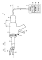
- FIG. 1 is a diagram illustrating a treatment system according to an embodiment.
- FIG. 2 is a diagram illustrating an ultrasonic transducer.
- FIG. 3 is a diagram showing the first electrode plate.
- FIG. 4 is a diagram illustrating the second electrode plate.
- FIG. 5 is a flowchart illustrating a method of manufacturing an ultrasonic transducer.
- FIG. 6 is a diagram illustrating a method of manufacturing an ultrasonic transducer.
- FIG. 7 is a diagram illustrating a method of manufacturing an ultrasonic transducer.
- FIG. 1 is a diagram showing a schematic configuration of a treatment system 1 according to the present embodiment.
- the treatment system 1 treats a target part of a living tissue by applying ultrasonic energy to a part to be treated (hereinafter, referred to as a target part).
- the treatment means, for example, coagulation and incision of the target site.
- This treatment system 1 includes an ultrasonic treatment instrument 2 and a control device 3 as shown in FIG.
- the ultrasonic treatment tool 2 is, for example, a medical treatment tool for treating a target site while passing through the abdominal wall.
- the ultrasonic treatment tool 2 includes a handpiece 4 and an ultrasonic transducer 5 as shown in FIG.
- the handpiece 4 includes a holding case 41, an operation knob 42, a switch 43, a sheath 44, a jaw 45, and an ultrasonic probe 46.
- the holding case 41 supports the entire ultrasonic treatment instrument 2.
- the operation knob 42 is movably attached to the holding case 41 and receives an opening / closing operation by an operator.
- the switch 43 is provided so as to be exposed to the outside of the holding case 41, and accepts an output start operation by the operator. Then, the switch 43 outputs an operation signal corresponding to the output start operation to the control device 3.
- the sheath 44 has a cylindrical shape.
- the central axis of the sheath 44 is referred to as a central axis Ax (FIG. 1).
- one side along the central axis Ax is referred to as a distal side Ar1 (FIG. 1), and the other side is referred to as a proximal side Ar2 (FIG. 1).
- the sheath 44 is attached to the holding case 41 by inserting a part of the base end Ar2 into the holding case 41 from the distal end Ar1 of the holding case 41.
- the jaw 45 is rotatably attached to the end of the distal end side Ar1 of the sheath 44, and holds the target portion between the jaw 45 and the distal end side Ar1 of the ultrasonic probe 46.
- An opening / closing mechanism (open / close mechanism) for opening / closing the jaw 45 with respect to the distal end portion Ar1 of the ultrasonic probe 46 in accordance with the opening / closing operation of the operation knob 42 by the operator inside the holding case 41 and the sheath 44 described above. (Not shown) is provided.
- the ultrasonic probe 46 corresponds to the treatment section according to the present invention.
- the ultrasonic probe 46 has a long shape extending linearly along the central axis Ax, and as shown in FIG. 1, the distal end Ar1 projects inside the sheath 44 in a state of protruding outside. It is inserted.
- the end of the base end side Ar2 of the ultrasonic probe 46 is connected to the ultrasonic transducer 6 (see FIG. 2A) constituting the ultrasonic transducer 5.
- the ultrasonic probe 46 transmits the ultrasonic vibration generated by the ultrasonic transducer 6 from the end of the base end Ar2 to the end of the distal end Ar1.
- the ultrasonic transducer 5 includes an ultrasonic transducer case 51 and an ultrasonic transducer 6 (see FIG. 2A).
- the ultrasonic transducer case 51 supports the ultrasonic transducer 6 and is detachably connected to the holding case 41.
- FIG. 2 is a diagram showing the ultrasonic transducer 6.
- the ultrasonic vibrator 6 generates an ultrasonic vibration under the control of the control device 3.
- the ultrasonic vibrator 6 is configured by a BLT (bolted Langevin vibrator).
- the ultrasonic vibrator 6 includes a vibrator main body 7, a front mass 8, and a back mass 9.
- the vibrator main body 7 includes first and second electrode plates 71 and 72, and a plurality of (six in the present embodiment) piezoelectric elements 73.
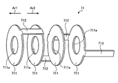
- FIG. 3 is a diagram illustrating the first electrode plate 71.
- the first electrode plate 71 is a portion to which a drive signal is supplied from the control device 3.
- the first electrode plate 71 includes a plurality of (four in the present embodiment) negative electrode plates 711 and a plurality (three in the present embodiment).
- a negative electrode wiring section 712 and a lead wire connection terminal 713 are provided.
- the plurality of negative electrode plates 711 each have a disk shape having an opening 711a at the center, and are arranged side by side along the central axis Ax.
- the plurality of negative electrode wiring portions 712 are portions for electrically connecting the outer edges of the negative electrode plates 711 adjacent to each other.
- the lead wire connection terminal 713 is a portion to which the lead wire C1 (FIG. 2A) constituting the electric cable C (FIGS. 1 and 2A) is connected.
- the lead wire connection terminal 713 extends from the outer edge of the negative electrode plate 711 located closest to the proximal end Ar2 of the plurality of negative electrode plates 711 toward the proximal end Ar2.
- FIG. 4 is a diagram illustrating the second electrode plate 72.
- the second electrode plate 72 is a portion to which a drive signal is supplied from the control device 3.
- the second electrode plate 72 includes a plurality (three in this embodiment) of positive electrode plates 721 and a plurality (two in this embodiment).
- a positive electrode wiring portion 722 and a lead wire connection terminal 723 are provided.
- the plurality of positive electrode plates 721 each have a disk shape having an opening 721a at the center, and are arranged side by side along the central axis Ax.
- the positive electrode plate 721 has substantially the same shape as the negative electrode plate 711.
- the plurality of positive electrode wiring portions 722 are portions for electrically connecting the outer edges of the positive electrode plates 721 adjacent to each other. Then, the negative electrode plates 711 and the positive electrode plates 721 are alternately arranged along the central axis Ax, as shown in FIG.
- the lead wire connection terminal 723 is a portion to which the lead wire C1 of the electric cable C is connected.
- the lead wire connection terminal 723 extends from the outer edge of the positive electrode plate 721 located closest to the proximal end Ar2 of the plurality of positive electrode plates 721 toward the proximal end Ar2.
- the plurality of piezoelectric elements 73 each have a disk shape having an opening (not shown) at the center, and are disposed between the negative electrode plate 711 and the positive electrode plate 721, respectively. That is, the plurality of piezoelectric elements 73 are stacked along the central axis Ax.
- the plurality of piezoelectric elements 73 generate a potential difference in the stacking direction along the central axis Ax in accordance with the drive signal supplied to the first and second electrode plates 71 and 72, so that the plurality of piezoelectric elements 73 move in the stacking direction.
- the expansion and contraction are alternately repeated.
- the ultrasonic vibrator 6 generates the ultrasonic vibration of the longitudinal vibration having the lamination direction as the vibration direction.
- the front mass 8 has a long shape extending linearly along the central axis Ax. As shown in FIG. 2A, the front mass 8 includes an element mounting portion 81, a cross-sectional area changing portion 82, and a probe mounting portion 83.
- the element mounting portion 81 is a bolt extending linearly along the central axis Ax, and includes openings 711a of the plurality of negative electrode plates 711, openings 721a of the plurality of positive electrode plates 721, and a plurality of piezoelectric elements 73. (Not shown). Then, as shown in FIG. 2A, a back mass 9 constituted by a nut is attached to an end of the element mounting portion 81 on the base end side Ar2.
- the cross-sectional area changing portion 82 corresponds to the horn according to the present invention.
- the cross-sectional area changing portion 82 is provided at an end of the element mounting portion 81 on the front end side Ar1 and is a portion that amplifies the amplitude of ultrasonic vibration. Further, as shown in FIG. 2A, the cross-sectional area change portion 82 is set such that the end of the base end Ar2 has a larger diameter than the element mounting portion 81, and the cross-sectional area increases toward the front end Ar1. It has a decreasing frustoconical shape.
- the plurality of negative electrode plates 711, the plurality of positive electrode plates 721, and the plurality of piezoelectric elements 73 pass through the element mounting portion 81 along the central axis Ax, and are located between the cross-sectional area changing portion 82 and the back mass 9. Are fastened together in a substantially cylindrical state.
- insulating plates 84 (FIG. 2A) are interposed between the cross-sectional area changing portion 82 and the piezoelectric element 73 and between the back mass 9 and the piezoelectric element 73, respectively. ing. As shown in FIG.
- the probe mounting portion 83 is provided at the end of the distal end side Ar1 in the cross-sectional area changing portion 82, and extends linearly along the central axis Ax. Then, an end of the proximal end Ar2 of the ultrasonic probe 46 is connected to an end of the distal end Ar1 of the probe mounting portion 83 in a state where the ultrasonic transducer 5 is connected to the handpiece 4.
- the ultrasonic treatment instrument 2 is detachably connected to the control device 3 by an electric cable C (FIG. 1). Then, the control device 3 controls the operation of the ultrasonic treatment instrument 2 overall through the electric cable C.
- the control device 3 includes an energy source 31, a detection circuit 32, and a processor 33, as shown in FIG.
- the energy source 31 outputs a drive signal, which is AC power, to the ultrasonic vibrator 6 via the electric cable C (a pair of lead wires C1) under the control of the processor 33.
- the detection circuit 32 detects a US signal based on a drive signal output from the energy source 31 to the ultrasonic transducer 6. Then, the detection circuit 32 outputs the detected US signal to the processor 33.
- the US signal includes a voltage phase signal (hereinafter, referred to as a US voltage phase signal) in the drive signal, a current phase signal (hereinafter, referred to as the US current phase signal) in the drive signal, Examples include a current value (hereinafter referred to as US current), a voltage value of the drive signal (hereinafter referred to as US voltage), an impedance value calculated from the US current and the US voltage (hereinafter referred to as US impedance), and the like. can do.
- the processor 33 is, for example, a CPU (Central Processing Unit) or an FPGA (Field-Programmable Gate Array), and controls the operation of the entire treatment system 1 according to a program stored in a memory (not shown). The function of the processor 33 will be described in “Operation of treatment system” below.
- the processor 33 controls the operation of the energy source 31, sweeps the frequency in the drive signal output from the energy source 31, and outputs the US signal (for example, US current, US current phase signal and US signal) output from the detection circuit 32.
- the resonance frequency of the ultrasonic transducer 6 is searched for based on the phase difference of the voltage phase signal.
- the processor 33 controls the operation of the energy source 31, and based on the US signal (for example, the US current, the phase difference between the US current phase signal and the US voltage phase signal, etc.), the drive output from the energy source 31.
- PLL control for locking the frequency in the signal to the searched resonance frequency is executed.
- the processor 33 executes the constant current control for keeping the US current constant.
- the ultrasonic vibrator 6 generates ultrasonic vibration (longitudinal vibration).
- the end of the base end side Ar2 in the cross-sectional area change portion 82 becomes a node P1 of the longitudinal vibration (FIG. 2B).
- the end of the distal end Ar1 in the probe mounting portion 83 and the end of the proximal end Ar2 in the back mass 9 are antinodes P2 and P3 (FIG. 2B) of the longitudinal vibration, respectively. That is, the total length of the ultrasonic vibrator 6 is about ⁇ of the wavelength of the longitudinal vibration.
- the longitudinal vibration generated by the ultrasonic transducer 6 is transmitted to the ultrasonic probe 46. Accordingly, the portion of the ultrasonic probe 46 on the distal end side Ar1 vibrates at a desired amplitude due to the longitudinal vibration. That is, an ultrasonic vibration is applied to the target portion gripped between the jaw 45 and the distal end Ar1 portion of the ultrasonic probe 46 from the distal end Ar1 portion. In other words, ultrasonic energy is applied to the target site from the front end side Ar1. As a result, frictional heat is generated between the portion on the front end side Ar1 and the target portion. Then, the target site is incised while coagulating.
- FIG. 5 is a flowchart illustrating a method of manufacturing the ultrasonic transducer 6.
- 6 and 7 are views for explaining a method of manufacturing the ultrasonic transducer 6.
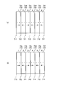
- FIG. 6A shows a configuration in which a plurality of piezoelectric elements 73 are arranged in a normal state.
- FIG. 6B shows a configuration in which the polarization direction of one piezoelectric element 73e of the plurality of piezoelectric elements 73 is reversed from the normal state.
- FIG. 6A shows a configuration in which a plurality of piezoelectric elements 73 are arranged in a normal state.
- FIG. 6B shows a configuration in which the polarization direction of one piezoelectric element 73e of the plurality of piezoelectric elements 73 is reversed from the normal state.
- the mounting positions of the plurality of piezoelectric elements 73 are set as mounting positions "1" to “6” in order from the side close to the cross-sectional area change portion 82 (node P1) toward the base end side Ar2. .
- the piezoelectric elements 73 at the mounting positions “1” to “6” are piezoelectric elements 73a to 73f, respectively.
- a positive charge inside the piezoelectric element 73 is represented by “+”
- a negative charge is represented by “ ⁇ ”
- a polarization direction is represented by an arrow.
- the positions of the negative electrode plate 711 and the positive electrode plate 721 are represented by alternate long and short dash lines.
- the normal state shown in FIG. 6A means that the plurality of piezoelectric elements 73 are positioned such that the negative charge “ ⁇ ” side faces the negative electrode plate 711 and the positive charge “+” side faces the positive electrode plate 721. Means a state where they are arranged.
- the operator performs the following step S1.
- the operator sets the plurality of piezoelectric elements 73 to the normal state shown in FIG. Further, the operator operates the control device 3 to cause the control device 3 to execute the constant current control of the ultrasonic vibrator 6. Thereby, the ultrasonic vibrator 6 generates ultrasonic vibration (longitudinal vibration).
- the plurality of piezoelectric elements 73 are set in the normal state, they expand at the same first timing and contract at the same second timing. Then, the worker measures the amplitude of the longitudinal vibration by using a vibrometer or the like.
- step S1 the operator determines whether the amplitude measured in step S1 is a desired amplitude (step S2). If it is determined that the amplitude is the desired amplitude (step S2: Yes), the operator determines to use the ultrasonic transducer 6 in a normal state (step S3). After step S3, the operator ends the method of manufacturing the ultrasonic vibrator 6.
- step S2 if it is determined that the amplitude is not the desired amplitude (step S2: No), the operator executes the following step S4.
- the worker normally changes the polarization direction of any one of the piezoelectric elements 73 (the piezoelectric element 73e in the example of FIG. 6B) at the mounting positions “1” to “6”. It is arranged in a posture inverted from the state.
- the operator operates the control device 3 and causes the control device 3 to execute the constant current control of the ultrasonic vibrator 6 in the same manner as in step S1. Thereby, the ultrasonic vibrator 6 generates ultrasonic vibration (longitudinal vibration). In this case, for example, in the state of FIG.
- the piezoelectric elements 73a to 73d and 73f expand at the same first timing and contract at the same second timing. It will be. That is, the piezoelectric elements 73a to 73d and 73f correspond to the first piezoelectric element according to the present invention. On the other hand, since the polarization direction of the piezoelectric element 73e is reversed from the normal state, the piezoelectric element 73e contracts at the first timing and expands at the second timing, contrary to the piezoelectric elements 73a to 73d and 73f. . That is, the piezoelectric element 73e corresponds to a second piezoelectric element according to the present invention. Then, the worker measures the amplitude of the longitudinal vibration by using a vibrometer or the like.
- step S4 the operator determines whether or not step S4 has been executed for all the piezoelectric elements 73 at the mounting positions "1" to "6" (step S5). If it is determined that the processing has not been performed for all the piezoelectric elements 73 (step S5: No), the operator returns to step S4.
- step S6 the operator executes the following step S6.
- the operator refers to the amplitude measured in step S4, and determines a mounting position having an amplitude close to a desired amplitude by inverting the polarization direction among the mounting positions “1” to “6”. Then, the operator decides to use the ultrasonic transducer 6 in a posture in which the polarization direction of the piezoelectric element 73 at the determined mounting position is reversed from the normal state.
- the mounting position “5” is determined as the mounting position where the polarization direction is reversed.
- amplitude increase rate The increase rate of each amplitude (hereinafter, referred to as amplitude increase rate) measured in step S4 with respect to the amplitude in the normal state measured in step S1, and the mounting positions "1" to "6" of piezoelectric element 73 whose polarization direction is reversed. Is as shown in FIG. Regardless of the case where the polarization directions of the piezoelectric elements 73a to 73f at the mounting positions "1" to “6" are reversed from the normal state, the amplitude increase rate is a positive value. In other words, the amplitude is higher than the amplitude in the normal state. This is considered for the following reasons.
- the amplitude increase rate is highest when the polarization direction of the piezoelectric element 73a at the mounting position “1” is reversed from the normal state, and the mounting position of the piezoelectric element 73 whose polarization direction is reversed is the mounting position “2”.
- the number decreases as one moves from “1” to “6” (as the distance from the node P1 increases). This is considered for the following reasons.
- the vibration contribution rate that contributes to the vibration of the ultrasonic vibrator 6 is highest for the piezoelectric element 73 a mounted near the node P 1, and mounted at the mounting positions “1” to “6”.
- the piezoelectric elements 73a to 73f become smaller in this order.
- the amplitude increase rate is increased, and if the polarization direction of the piezoelectric element 73 having a low vibration contribution rate is reversed from the normal state, the amplitude increase rate is increased. Becomes lower.
- the ultrasonic vibrator 6 the plurality of piezoelectric elements 73 expand at the first timing and contract at the second timing, and contract at the first timing.
- a piezoelectric element 73e that expands at the second timing. That is, a desired amplitude can be obtained only by reversing the polarization direction of the piezoelectric element 73e from the normal state among the plurality of piezoelectric elements 73.
- the plurality of piezoelectric elements 73 are stacked along the central axis Ax on the base end side Ar2 with respect to the node P1.
- the ultrasonic vibrator 6 has only one longitudinal vibration node P1, and its entire length is about ⁇ of the wavelength of the longitudinal vibration. For this reason, it is possible to reduce the size of the ultrasonic vibrator 6 and, consequently, the size of the ultrasonic treatment instrument 2.
- the present invention should not be limited only to the above-described embodiments.
- the plurality of piezoelectric elements 73 are constituted by six sheets, but may be constituted by other numbers.
- the fifth piezoelectric element 73e from the node P1 is the second piezoelectric element according to the present invention.
- the present invention is not limited to this.
- Such a second piezoelectric element may be used.
- the number of the second piezoelectric elements according to the present invention is not limited to one, and may be another number.
- the piezoelectric element 73e which is the second piezoelectric element according to the present invention, has the first timing opposite to the piezoelectric elements 73a to 73d, 73f, which are the first piezoelectric elements according to the present invention.
- And expanded at the second timing but is not limited to this.
- the expansion and contraction timings of the second piezoelectric element according to the present invention are different from those of the first piezoelectric element according to the present invention, the expansion and contraction timings may be other timings.
- the vibration efficiency of the ultrasonic vibrator 6 is higher than that in the normal state. It is considered that the amplitude becomes higher than the amplitude in the normal state because the amplitude becomes worse.
- the ultrasonic vibrator 6 has a total length of about ⁇ of the wavelength of the ultrasonic vibration.
- the present invention is not limited to this. May be provided.
- the ultrasonic treatment tool 2 employs a configuration in which ultrasonic energy is applied to a target site.
- a configuration for applying at least one of energy and thermal energy may be employed.
- giving high frequency energy to the target portion means flowing high frequency current to the target portion.
- to apply heat energy to the target portion means to transfer heat of a heater or the like to the target portion.
Landscapes
- Health & Medical Sciences (AREA)
- Engineering & Computer Science (AREA)
- Mechanical Engineering (AREA)
- Surgery (AREA)
- Life Sciences & Earth Sciences (AREA)
- Heart & Thoracic Surgery (AREA)
- Nuclear Medicine, Radiotherapy & Molecular Imaging (AREA)
- Biomedical Technology (AREA)
- Dentistry (AREA)
- Medical Informatics (AREA)
- Molecular Biology (AREA)
- Animal Behavior & Ethology (AREA)
- General Health & Medical Sciences (AREA)
- Public Health (AREA)
- Veterinary Medicine (AREA)
- Surgical Instruments (AREA)
- Apparatuses For Generation Of Mechanical Vibrations (AREA)
Abstract
L'invention concerne un transducteur à ultrasons 6 comprenant un corps de transducteur 7 qui génère une vibration à ultrasons qui est destinée à fabriquer une partie de traitement qui traite un tissu biologique vibrant. Le corps de transducteur 7 a une pluralité d'éléments piézoélectriques 73 qui se dilatent et se contractent de façon alternée et répétée conformément à un signal d'entraînement fourni. La pluralité d'éléments piézoélectriques 73 sont empilés dans la direction d'expansion/contraction et fixés d'un seul tenant. La pluralité d'éléments piézoélectriques 73 comprend : des premiers éléments piézoélectriques qui se dilatent à un premier instant et se contractent à un second instant ; et des seconds éléments piézoélectriques qui ont une synchronisation d'expansion et de contraction qui est différente des premiers éléments piézoélectriques.
Priority Applications (4)
| Application Number | Priority Date | Filing Date | Title |
|---|---|---|---|
| PCT/JP2018/032216 WO2020044513A1 (fr) | 2018-08-30 | 2018-08-30 | Transducteur à ultrasons, instrument de traitement par ultrasons et procédé de production pour transducteur à ultrasons |
| JP2020539964A JP7119099B2 (ja) | 2018-08-30 | 2018-08-30 | 超音波振動子、超音波処置具、及び超音波振動子の製造方法 |
| CN201880096944.XA CN112638293B (zh) | 2018-08-30 | 2018-08-30 | 超声波振子、超声波处置器具及超声波振子的制造方法 |
| US17/185,613 US12121257B2 (en) | 2018-08-30 | 2021-02-25 | Ultrasound transducer, ultrasound treatment tool, and manufacturing method of ultrasound transducer |
Applications Claiming Priority (1)
| Application Number | Priority Date | Filing Date | Title |
|---|---|---|---|
| PCT/JP2018/032216 WO2020044513A1 (fr) | 2018-08-30 | 2018-08-30 | Transducteur à ultrasons, instrument de traitement par ultrasons et procédé de production pour transducteur à ultrasons |
Related Child Applications (1)
| Application Number | Title | Priority Date | Filing Date |
|---|---|---|---|
| US17/185,613 Continuation US12121257B2 (en) | 2018-08-30 | 2021-02-25 | Ultrasound transducer, ultrasound treatment tool, and manufacturing method of ultrasound transducer |
Publications (1)
| Publication Number | Publication Date |
|---|---|
| WO2020044513A1 true WO2020044513A1 (fr) | 2020-03-05 |
Family
ID=69643774
Family Applications (1)
| Application Number | Title | Priority Date | Filing Date |
|---|---|---|---|
| PCT/JP2018/032216 Ceased WO2020044513A1 (fr) | 2018-08-30 | 2018-08-30 | Transducteur à ultrasons, instrument de traitement par ultrasons et procédé de production pour transducteur à ultrasons |
Country Status (4)
| Country | Link |
|---|---|
| US (1) | US12121257B2 (fr) |
| JP (1) | JP7119099B2 (fr) |
| CN (1) | CN112638293B (fr) |
| WO (1) | WO2020044513A1 (fr) |
Families Citing this family (1)
| Publication number | Priority date | Publication date | Assignee | Title |
|---|---|---|---|---|
| US11903604B2 (en) * | 2021-02-18 | 2024-02-20 | Olympus Corporation | Ultrasound transducer and treatment tool that includes a piezoelectric element and a horn |
Citations (8)
| Publication number | Priority date | Publication date | Assignee | Title |
|---|---|---|---|---|
| JPH0286874A (ja) * | 1988-06-17 | 1990-03-27 | Olympus Optical Co Ltd | 超音波振動子の駆動回路 |
| JPH09155288A (ja) * | 1995-12-05 | 1997-06-17 | Sumitomo Bakelite Co Ltd | 振動子取付け方法 |
| JP2001179179A (ja) * | 1999-12-27 | 2001-07-03 | Taga Electric Co Ltd | 超音波振動子及び複合振動発生超音波振動子 |
| JP2002533152A (ja) * | 1998-12-30 | 2002-10-08 | ファーマソニックス,インコーポレイテッド | 均一エネルギー線量を送達するための治療用超音波カテーテル |
| US20120293044A1 (en) * | 2008-02-22 | 2012-11-22 | Piezo-Innovations | Ultrasonic torsional mode and longitudinal-torsional mode transducer |
| US20150088154A1 (en) * | 2013-09-25 | 2015-03-26 | Jeffrey J. Vaitekunas | Ultrasonic generator systems and methods |
| WO2016046887A1 (fr) * | 2014-09-22 | 2016-03-31 | オリンパス株式会社 | Vibrateur à ultrasons et outil de traitement par ultrasons |
| WO2017109917A1 (fr) * | 2015-12-24 | 2017-06-29 | オリンパス株式会社 | Transducteur à ultrasons |
Family Cites Families (12)
| Publication number | Priority date | Publication date | Assignee | Title |
|---|---|---|---|---|
| JPH06319734A (ja) * | 1993-04-16 | 1994-11-22 | Hewlett Packard Co <Hp> | 多層音響変換器 |
| JPH08280098A (ja) * | 1995-04-07 | 1996-10-22 | Olympus Optical Co Ltd | 超音波探触子用圧電素子 |
| US6761692B2 (en) * | 2001-06-25 | 2004-07-13 | Eagle Ultrasound As | High frequency and multi frequency band ultrasound transducers based on ceramic films |
| CN1813487B (zh) * | 2003-12-26 | 2011-07-13 | 日本电气株式会社 | 压电致动器 |
| DE102008028885A1 (de) * | 2008-06-18 | 2009-12-31 | Epcos Ag | Verfahren zur Abstimmung einer Resonanzfrequenz eines piezoelektrischen Bauelementes |
| WO2010092724A1 (fr) | 2009-02-14 | 2010-08-19 | 国立大学法人東北大学 | Générateur électrique |
| JP2011125815A (ja) * | 2009-12-18 | 2011-06-30 | Canon Inc | 振動装置の駆動回路、及び振動装置の駆動方法 |
| JP5708167B2 (ja) * | 2011-04-06 | 2015-04-30 | コニカミノルタ株式会社 | 超音波探触子及び超音波診断装置 |
| CN103547380B (zh) * | 2011-08-19 | 2015-10-07 | 奥林巴斯医疗株式会社 | 超声波产生装置及其制造方法、超声波处理装置及其制造方法 |
| EP2822297B1 (fr) * | 2012-02-28 | 2020-01-08 | Kyocera Corporation | Élément de vibration piézoélectrique, appareil de vibration piézoélectrique et terminal mobile |
| JP6716082B2 (ja) * | 2015-11-10 | 2020-07-01 | 有限会社Uwave | ランジュバン型超音波振動子の縦・ねじり振動の励起方法 |
| WO2017147721A1 (fr) * | 2016-03-04 | 2017-09-08 | Xact Downhole Telemetry Inc. | Procédé et système de réglage de tension appliquée à une pile piézoélectrique d'un émetteur acoustique de fond de trou |
-
2018
- 2018-08-30 JP JP2020539964A patent/JP7119099B2/ja active Active
- 2018-08-30 CN CN201880096944.XA patent/CN112638293B/zh active Active
- 2018-08-30 WO PCT/JP2018/032216 patent/WO2020044513A1/fr not_active Ceased
-
2021
- 2021-02-25 US US17/185,613 patent/US12121257B2/en active Active
Patent Citations (8)
| Publication number | Priority date | Publication date | Assignee | Title |
|---|---|---|---|---|
| JPH0286874A (ja) * | 1988-06-17 | 1990-03-27 | Olympus Optical Co Ltd | 超音波振動子の駆動回路 |
| JPH09155288A (ja) * | 1995-12-05 | 1997-06-17 | Sumitomo Bakelite Co Ltd | 振動子取付け方法 |
| JP2002533152A (ja) * | 1998-12-30 | 2002-10-08 | ファーマソニックス,インコーポレイテッド | 均一エネルギー線量を送達するための治療用超音波カテーテル |
| JP2001179179A (ja) * | 1999-12-27 | 2001-07-03 | Taga Electric Co Ltd | 超音波振動子及び複合振動発生超音波振動子 |
| US20120293044A1 (en) * | 2008-02-22 | 2012-11-22 | Piezo-Innovations | Ultrasonic torsional mode and longitudinal-torsional mode transducer |
| US20150088154A1 (en) * | 2013-09-25 | 2015-03-26 | Jeffrey J. Vaitekunas | Ultrasonic generator systems and methods |
| WO2016046887A1 (fr) * | 2014-09-22 | 2016-03-31 | オリンパス株式会社 | Vibrateur à ultrasons et outil de traitement par ultrasons |
| WO2017109917A1 (fr) * | 2015-12-24 | 2017-06-29 | オリンパス株式会社 | Transducteur à ultrasons |
Also Published As
| Publication number | Publication date |
|---|---|
| CN112638293A (zh) | 2021-04-09 |
| CN112638293B (zh) | 2024-07-12 |
| JPWO2020044513A1 (ja) | 2021-08-26 |
| US20210177453A1 (en) | 2021-06-17 |
| JP7119099B2 (ja) | 2022-08-16 |
| US12121257B2 (en) | 2024-10-22 |
Similar Documents
| Publication | Publication Date | Title |
|---|---|---|
| US9693793B2 (en) | Ultrasonic probe and ultrasonic treatment instrument | |
| JP6261833B2 (ja) | 超音波振動子、超音波処置具、および超音波治療装置 | |
| JP2009511206A (ja) | 医療用超音波システム、ハンドピース、ならびに、形成および同調のための方法 | |
| CN108463292B (zh) | 振动传递构件、超声波处置器具以及振动体单元 | |
| JP6157747B2 (ja) | 振動体ユニットおよび超音波プローブ | |
| US20170239497A1 (en) | Vibration generating unit, vibrating body unit and ultrasonic treatment instrument | |
| CN109845293A (zh) | 振动传递体、超声波转换器构造体及医疗设备 | |
| JP7119099B2 (ja) | 超音波振動子、超音波処置具、及び超音波振動子の製造方法 | |
| CN112040890A (zh) | 医疗设备系统、异常判定方法以及异常判定程序 | |
| JP6437562B2 (ja) | 超音波振動子及び超音波処置具 | |
| US10182963B2 (en) | Vibration generating unit, vibrating body unit and ultrasonic treatment instrument | |
| US11903604B2 (en) | Ultrasound transducer and treatment tool that includes a piezoelectric element and a horn | |
| CN113573653B (zh) | 控制装置、超声波处置系统以及谐振频率探查方法 | |
| JPWO2018078797A1 (ja) | 医療用処置装置、及び医療用処置装置の作動方法 | |
| US10064641B2 (en) | Ultrasonic probe and ultrasonic treatment instrument | |
| WO2017149614A1 (fr) | Instrument de traitement aux ultrasons pour les articulations et système de traitement aux ultrasons pour les articulations | |
| JP2015144788A (ja) | 超音波振動デバイスおよび超音波医療装置 | |
| Kukic et al. | High Power Low Impedance Therapeutic Intracavitary Phased Array |
Legal Events
| Date | Code | Title | Description |
|---|---|---|---|
| 121 | Ep: the epo has been informed by wipo that ep was designated in this application |
Ref document number: 18931919 Country of ref document: EP Kind code of ref document: A1 |
|
| ENP | Entry into the national phase |
Ref document number: 2020539964 Country of ref document: JP Kind code of ref document: A |
|
| NENP | Non-entry into the national phase |
Ref country code: DE |
|
| 122 | Ep: pct application non-entry in european phase |
Ref document number: 18931919 Country of ref document: EP Kind code of ref document: A1 |