WO2020044518A1 - Système de synchronisation, système de synchronisation de mesure, procédé de synchronisation, et programme - Google Patents
Système de synchronisation, système de synchronisation de mesure, procédé de synchronisation, et programme Download PDFInfo
- Publication number
- WO2020044518A1 WO2020044518A1 PCT/JP2018/032228 JP2018032228W WO2020044518A1 WO 2020044518 A1 WO2020044518 A1 WO 2020044518A1 JP 2018032228 W JP2018032228 W JP 2018032228W WO 2020044518 A1 WO2020044518 A1 WO 2020044518A1
- Authority
- WO
- WIPO (PCT)
- Prior art keywords
- time
- signal
- measurement
- point
- switch
- Prior art date
- Legal status (The legal status is an assumption and is not a legal conclusion. Google has not performed a legal analysis and makes no representation as to the accuracy of the status listed.)
- Ceased
Links
Images


Classifications
-
- H—ELECTRICITY
- H02—GENERATION; CONVERSION OR DISTRIBUTION OF ELECTRIC POWER
- H02B—BOARDS, SUBSTATIONS OR SWITCHING ARRANGEMENTS FOR THE SUPPLY OR DISTRIBUTION OF ELECTRIC POWER
- H02B3/00—Apparatus specially adapted for the manufacture, assembly, or maintenance of boards or switchgear
Definitions
- the present invention relates to a synchronization system, a measurement synchronization system, a synchronization method, and a program.
- Patent Document 1 there is known a positioning system that acquires measurement data from each of a plurality of measurement devices at a synchronized time.
- Patent Literature 1 synchronizes a plurality of field devices by transmitting time information for synchronizing time, and uses measurement data at the same time to detect abnormalities such as noise and equipment failure or the like. This is for estimating a place where an abnormality has occurred.
- information for synchronizing the time is transmitted from a predetermined device to synchronize the time of each field device.
- the switching surge is measured at the power receiving place. .
- the present invention for solving the above-mentioned problems is provided at a first point where a power station having a switch connected to a transmission and distribution line is present and transmitted at a predetermined time from a first clock device whose time is calibrated by radio waves.
- the first control unit outputs a switching signal to the switch based on the first signal
- a second control point is provided at a control point where a switching surge flows through the transmission and distribution line due to the switching operation of the switch.
- a delay calculating device that receives a second signal at the predetermined time from a second clock device whose time is calibrated by radio waves, wherein the delay calculating device is configured such that at the predetermined time, the switch is the switch.
- An arrival time calculation unit that adds a delay time required to complete the opening operation or the closing operation after receiving the opening / closing signal, and calculates an arrival time indicating a time when the opening / closing surge reaches the second point; measuring device The switching surge to reach the second point so as to measure the arrival time, having a signal output section for outputting a start signal indicating the start of measurement to the measuring apparatus.
- the measuring device since the switching surge generated at a predetermined point is measured at different points, the measuring device can be measured at an appropriate measurement timing.
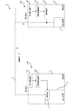
- FIG. 1 is a configuration diagram illustrating a measurement synchronization system according to an embodiment.
- FIG. 2 is a diagram illustrating a hardware configuration of a reception control device according to the embodiment.
- FIG. 3 is a diagram illustrating a software configuration of the reception control device according to the embodiment.
- FIG. 2 is a diagram illustrating a hardware configuration of the delay operation device according to the embodiment.
- FIG. 3 is a diagram illustrating a software configuration of the delay operation device according to the embodiment.
- 5 is a time chart illustrating an example of a delay time according to the embodiment. It is a flowchart which shows the processing procedure of the measurement synchronous system which concerns on this embodiment.
- the measurement synchronization system 10 transmits a switching surge generated by a switching operation of a switch provided at a predetermined point (hereinafter, referred to as a “first point”) of the electric substation 1 to a predetermined point of the control center 4 (hereinafter, “second point”).
- the electric station 1 is, for example, a substation or a switchyard, and is a facility having a switch 3 in a part of the power equipment 2.
- the switch 3 is a device having a contact portion for turning on and off the transmission and distribution line 6, and is, for example, a circuit breaker or a disconnector.
- the control center 4 is a facility having a low-voltage facility 5 provided in a mountain, for example, where an optical line or the like is not opened.
- a delay time due to the mechanical operation of the switch 3 occurs between the time when the switch 3 is output and the time when the switch 3 completes the operation.
- the occurrence of the above-mentioned delay time exceeds the time width that can be measured by the measuring device 150, and an event that the switching surge cannot be measured occurs. Had occurred.
- a clock device whose time is calibrated by radio waves is provided at the first point and the second point, and the time is synchronized between the first point and the second point, and the mechanical operation of the switch 3 is performed.
- the switching surge is measured by the measuring device 150 at the second point in consideration of the delay time due to the operation.
- the measuring device 150 can measure the switching surge within the measurable time width.
- the measuring device 150 has to measure the opening / closing surge within the time width when the measurable time width is “4 seconds”, depending on the memory capacity and the measurement range.
- FIG. 1 is a configuration diagram showing a measurement synchronization system 10.
- the measurement synchronization system 10 includes a first clock device 110, a second clock device 120, a reception control device 130, a delay calculation device 140, and a measurement device 150.
- a system including the first clock device 110, the second clock device 120, the reception control device 130, and the delay operation device 140 will be described as a "synchronous system 100".
- the synchronization system 100 receives a predetermined signal from the first and second timepiece devices 110 and 120, and takes the delay time due to the mechanical operation of the switch 3 into consideration so that the measuring device 150 reliably measures the switching surge. It is a system for. As shown in FIG. 1, the synchronization system 100 includes a first clock device 110, a second clock device 120, a reception control device 130, and a delay operation device 140. Hereinafter, each device will be described.
- the first clock device 110 and the second clock device 120 are clock devices that are installed at the first point and the second point, respectively, and whose time is calibrated by radio waves. Specifically, it is a radio clock, a GPS clock, a mobile phone, or the like.
- the first and second timepiece devices 110 and 120 have a function of outputting a predetermined signal at a predetermined time.
- the predetermined signal is, for example, an alarm signal (TTL signal).
- TTL signal alarm signal
- the first and second clock devices 110 and 120 are communicably connected to a reception control device 130 and a delay calculation device 140, respectively, and a predetermined signal is transmitted to the reception control device 130 and the delay calculation device 140, respectively. Is output.
- the connection between the first and second clock devices 110 and 120 and the reception control device 130 and the delay calculation device 140 may be either wireless or wired, and is not particularly limited.
- the reception control device 130 can output an opening / closing signal at a predetermined time based on a predetermined signal, and, as described later, the delay calculation device 140 outputs a predetermined signal based on the predetermined signal.
- the start signal can be output at the time obtained by adding the delay time to the time.
- the reception control device 130 is a device that is installed at a first point and outputs a switching signal to the switch 3 based on a first signal received from the first clock device 110 at a predetermined time.
- FIG. 2 is a diagram showing a hardware configuration of the reception control device 130.
- the hardware of the reception control device 130 includes a processor 131, a memory 132, a storage device 133, an input device 134, an output device 135, and a communication device 136.
- the processor 131 is, for example, an MPU, a CPU, or the like.
- the memory 132 is, for example, a RAM, a ROM, an NVRAM, or the like.
- the storage device 133 is, for example, a RAM, a ROM, an NVRAM, or the like.
- the input device 134 is a user interface that receives an operation input from a user, and is, for example, an operation input device (a keyboard, a mouse, a touch panel, or the like), a voice input device (a microphone, or the like), or the like.
- the output device 135 is a user interface that provides various types of information to the user, and is, for example, a display device (such as a liquid crystal monitor) or an audio output device (such as a speaker).
- the communication device 136 is an interface for wireless communication or wired communication for connecting to the first timepiece device 110 and the control circuit.
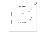
- FIG. 3 is a diagram illustrating an example of a software configuration of the reception control device 130.
- the software of the reception control device 130 has a functional unit including an acquisition unit 130a and a first signal output unit 130b.
- These functional units are realized, for example, by the processor 131 of the reception control device 130 reading and executing a program stored in the memory 132.
- these functional units may be realized by hardware such as an ASIC, for example. Further, it may be realized by the processor 131 reading and executing a program stored in an external storage medium.
- the acquisition unit 130a acquires a predetermined signal from the first timepiece device 110 via the communication device 136.
- the first signal output unit 130b outputs a switching signal to a control circuit that controls the switch 3.
- the control circuit (not shown) may be a circuit configured by a relay or a circuit configured by a programmable logic controller, and the circuit configuration is not particularly limited. Accordingly, the switch 3 starts mechanical operation based on the operation signal from the control circuit. Note that there is a delay time due to the mechanical operation of the switch 3 from the output of the switch signal from the first signal output unit 130b to the completion of the operation of the switch 3 (open or closed).
- the delay calculation device 140 is installed at the second point, and indicates the start of measurement to the measurement device 150 in consideration of the delay time based on the second signal transmitted from the second clock device 120 at a predetermined time. It is a device that outputs a start signal.
- the predetermined time is the same as the time when the first clock device 110 outputs the first signal. This allows the reception control device 130 and the delay calculation device 140 to synchronize the time.
- FIG. 4 is a diagram showing a hardware configuration of the delay operation device 140.
- the hardware of the delay operation device 140 includes a processor 141, a memory 142, a storage device 143, an input device 144, an output device 145, and a communication device 146.
- the processor 141 is, for example, an MPU, a CPU, or the like.
- the memory 142 is, for example, a RAM, a ROM, an NVRAM, or the like.
- the storage device 143 is, for example, a RAM, a ROM, an NVRAM, or the like.
- the input device 144 is a user interface that receives an operation input from the user, and is, for example, an operation input device (a keyboard, a mouse, a touch panel, or the like), a voice input device (a microphone, or the like), or the like.
- the output device 145 is a user interface that provides various kinds of information to the user, and is, for example, a display device (such as a liquid crystal monitor) and an audio output device (such as a speaker).
- the communication device 146 is an interface for wireless communication or wired communication for connecting to the second clock device 120 and the measuring device 150.
- FIG. 5 is a diagram showing an example of a software configuration of the delay operation device 140.
- the software of the delay calculation device 140 has functional units of an acquisition unit 140a, an arrival time calculation unit 140b, and a second signal output unit 140c. These functional units are realized, for example, by the processor 141 of the delay operation device 140 reading and executing a program stored in the memory 142. Note that these functional units may be realized by hardware such as an ASIC, for example. Also, the present invention may be realized by the processor 141 reading and executing a program stored in an external storage medium.
- the acquisition unit 140a acquires a predetermined signal from the second clock device 120 via the communication device 146.
- the arrival time calculation unit 140b adds, at a predetermined time, a delay time required from when the switch 3 receives the switching signal to when the switch 3 completes the switching operation, to calculate the switching surge generated at the first point. Calculates the arrival time indicating the time at which the vehicle reaches the second point.
- the delay time will be described with reference to FIG.
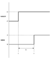
- FIG. 6 is a time chart showing the delay time ( ⁇ t).
- the upper graph in FIG. 6 is a graph in which the time (time a) when the reception control device 130 outputs the switching signal to the switch 3 based on the first signal is plotted as rising “ON”.
- the arrival time calculation unit 140b calculates the arrival time by adding the delay time specified above to a predetermined time.
- the second signal output unit 140c outputs a start signal indicating the start of measurement to the measuring device 150 so that the measuring device 150 can measure the switching surge at the arrival time.
- the second signal output unit 140c sets the timing for outputting the start signal in consideration of the storage capacity of the measuring device 150. Specifically, for example, when the measurable time of the measuring device 150 is “4 seconds”, the second signal output unit 140c sets the arrival time at which the switching surge reaches the measuring device 150 within the measurable time.
- a start signal is output to measurement device 150 to be included.
- the timing is preset in the delay calculation device 140 in consideration of the specifications of the switch 3. Thereby, the measuring device 150 can reliably measure the switching surge generated at the first point at the second point.
- the synchronization system 100 may not include the first clock device 110 and the second clock device 120. In this case, if the reception control device 130 and the delay calculation device 140 of the measurement synchronization system 10 are configured to receive the first signal and the second signal from a clock device installed separately from the synchronization system 100, Good.
- the measuring device 150 is a device that is installed at the second point and measures the switching surge based on the start signal output from the delay calculating device 140.
- the measurement device 150 is preferably, for example, a memory high coder. Since the memory high coder generally has a trigger function, the second signal output from the second clock device 120 can be used as a trigger.
- the measuring device 150 may be a sound detecting device that detects sound generated in the low-voltage equipment 5 by the switching surge, a light detecting device that detects light, or an electric field that measures electric field intensity. It may be a measuring device. That is, the measuring device 150 may be any device that detects a phenomenon caused by the switching surge.
- the measuring device 150 may be a digital oscilloscope or an analog oscilloscope.
- a digital oscilloscope any of a DSO (digital storage oscilloscope), a DPO (digital phosphor oscilloscope), an MSO (mixed signal oscilloscope), and a digital sampling oscilloscope may be used, and there is no particular limitation.
- Digital oscilloscopes are excellent in observing high-speed phenomena.
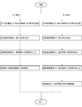
- FIG. 7 is a flowchart showing a processing procedure of the measurement synchronization system 10. The processing procedure of the measurement synchronization system 10 will be described with reference to FIG. In the following processing procedure, the step of the first point is started from S10, and the step of the second point is started from S20.
- the worker sets the signal output time of the first clock device 110 at the first point. Further, the worker sets the signal output time of the second clock device 120 at the second point to the same time as the signal output time of the first clock device 110. Thereby, the time can be synchronized between the first point and the second point.
- the first clock device 110 outputs a first signal to the reception control device 130 at a predetermined time set in advance (S10). Since the first clock device 110 is a radio clock or a GPS clock, it can output the first signal at an accurate time.
- the reception control device 130 receives the first signal (S11). Receiving the first signal, the reception control device 130 outputs a switching signal to a control circuit that controls the switch 3 (S12). The control circuit (not shown) opens and closes the switch 3 upon receiving the switching signal (S13). In this series of operations, a delay time occurs from the output of the switching signal to the completion of the switching operation of the switch 3.
- the processing procedure at the second point is a procedure for measuring the switching surge with the measuring device 150 in consideration of the delay time generated at the first point.
- the second clock device 120 outputs the second signal to the delay calculation device 140 at the same time as the time when the first signal is output (S20). Since the second clock device 120 is a radio clock or a GPS clock, like the first clock device 110, the second clock device 120 outputs the second signal at an accurate time.
- the delay calculation device 140 receives the second signal (S21). Upon receiving the second signal, the delay calculation device 140 specifies the delay time and calculates the arrival time at which the switching surge reaches the second point (S22). The arrival time is as described above.
- the delay calculation device 140 outputs a start signal indicating the start of measurement to the measurement device 150 in consideration of the arrival time (S23). Upon receiving the start signal, the measuring device 150 continuously measures the electric quantities of the circuit for a predetermined time (S24). Thereby, the measuring device 150 can measure the switching surge generated at the first point and flowing into the second point via the transmission and distribution line 6.
- the synchronization system 100 is installed at the first point (electric station 1) where the switch 3 connected to the transmission and distribution line 6 exists, and the first system whose time is calibrated by radio waves. Based on a first signal transmitted from the clock device 110 at a predetermined time, a reception control device 130 that outputs a switching signal to the switch 3, and a switching surge flows through the transmission and distribution line 6 by the switching operation of the switch 3.
- a delay calculating device 140 that is installed at a second point where the control center 4 is located and whose time is calibrated by radio waves and receives a second signal at a predetermined time from a second clock device 120; And adding a delay time required from when the switch 3 receives the switching signal to when the switching operation is completed to a predetermined time to calculate an arrival time indicating a time when the switching surge reaches the second point.
- Time calculation unit 14 And b, and switching surges that measuring device 150 reaches the second location so as to measure the arrival time a second signal output section 140c outputs a start signal indicating the start of measurement to the measuring apparatus 150, a.
- the measuring device 150 can be measured at an appropriate measurement timing.
- the synchronization system 100 is installed at a first point, has a function of calibrating the time by radio waves, and outputs a first signal.
- a second clock device 120 having a function of calibrating the time by radio waves and outputting a second signal. According to the present embodiment, by incorporating the first timepiece device 110 and the second timepiece device 120 in the same system, it is possible to secure the integrity of the system and increase the versatility.
- the first clock device 110 and the second clock device 120 of the synchronization system 100 are radio clocks or GPS clocks. According to the present embodiment, the cost can be reduced by employing a general-purpose timepiece device.
- the measurement synchronization system 10 receives the synchronization system 100 and a start signal output from the second signal output unit 140c of the synchronization system 100, and detects switching surge at the second point based on the start signal. And a measuring device 150 for measuring. According to the present embodiment, by incorporating the measuring device 150 into the same system, the integrity of the system can be ensured, and the versatility can be improved.
- the measuring device 150 of the measurement synchronization system 10 is a memory high coder, a digital oscilloscope, or an analog oscilloscope.
- the memory high coder has many types of measurement targets and has a trigger function, and thus is suitable for the present system.
- Digital oscilloscopes are abundant in variety and versatile, so design costs can be reduced. By configuring the analog oscilloscope with the measuring device 150 that has been widely used in the past, the system construction cost can be reduced.
- the measurement synchronization system 10 for measuring the switching surge generated at the first point by the measuring device 150 at the second point has been described, but the present invention is not limited to this.
- the measurement synchronization system 10 may be a system in which the switching surge generated at the first location is similarly measured by the measurement device 150 at the second location and the measurement device 150 at the third location. That is, the reception control device 130 is installed at the first location, and the delay calculation device 140 is installed at the other multiple locations so that the switching surge generated at the first location can be measured at each of the multiple locations.
- Each of the delay calculation devices 140 calculates the arrival time in consideration of the delay time as described above.
- the measurement devices 150 at the other multiple points can measure the switching surge generated at the first point.
Landscapes
- Engineering & Computer Science (AREA)
- Manufacturing & Machinery (AREA)
- Power Engineering (AREA)
- Electric Clocks (AREA)
Abstract
La présente invention concerne un système synchrone, comprenant : un dispositif de commande récepteur installé à un premier emplacement où se situe un commutateur connecté à une ligne de transmission et de distribution, et émettant un signal de commutation au commutateur en fonction d'un premier signal émis à un moment prédéfini par un premier dispositif d'horloge, dont le temps est étalonné par une onde radioélectrique ; et un dispositif de calcul de retard installé à un second emplacement où se situe une station de commande dans laquelle une surtension de commutation circule à travers la ligne de transmission et de distribution en raison du fonctionnement en circuit ouvert ou du fonctionnement en circuit fermé du commutateur, et recevant un second signal au moment prédéfini provenant d'un second dispositif d'horloge, dont le temps est étalonné par l'onde radioélectrique. Le dispositif de calcul de retard comprend : une unité de calcul de temps d'arrivée servant à ajouter, au moment prédéfini, un temps de retard requis à partir du moment où le commutateur a reçu le signal de commutation jusqu'à la fin du fonctionnement en circuit ouvert ou du fonctionnement en circuit fermé, calculant ainsi un temps d'arrivée indiquant le moment où la surtension de commutation atteint le second emplacement ; et une unité d'émission de signal servant à émettre un signal de début destiné à signifier le début d'une mesure à un dispositif de mesure de sorte que le dispositif de mesure puisse mesurer, au moment de l'arrivée, la surtension de commutation qui atteint le second emplacement.
Priority Applications (2)
| Application Number | Priority Date | Filing Date | Title |
|---|---|---|---|
| PCT/JP2018/032228 WO2020044518A1 (fr) | 2018-08-30 | 2018-08-30 | Système de synchronisation, système de synchronisation de mesure, procédé de synchronisation, et programme |
| JP2018566318A JP6508444B1 (ja) | 2018-08-30 | 2018-08-30 | 同期システム、測定同期システム、同期方法、プログラム |
Applications Claiming Priority (1)
| Application Number | Priority Date | Filing Date | Title |
|---|---|---|---|
| PCT/JP2018/032228 WO2020044518A1 (fr) | 2018-08-30 | 2018-08-30 | Système de synchronisation, système de synchronisation de mesure, procédé de synchronisation, et programme |
Publications (1)
| Publication Number | Publication Date |
|---|---|
| WO2020044518A1 true WO2020044518A1 (fr) | 2020-03-05 |
Family
ID=66429817
Family Applications (1)
| Application Number | Title | Priority Date | Filing Date |
|---|---|---|---|
| PCT/JP2018/032228 Ceased WO2020044518A1 (fr) | 2018-08-30 | 2018-08-30 | Système de synchronisation, système de synchronisation de mesure, procédé de synchronisation, et programme |
Country Status (2)
| Country | Link |
|---|---|
| JP (1) | JP6508444B1 (fr) |
| WO (1) | WO2020044518A1 (fr) |
Citations (6)
| Publication number | Priority date | Publication date | Assignee | Title |
|---|---|---|---|---|
| JPH07264766A (ja) * | 1994-02-07 | 1995-10-13 | Toshiba Corp | 保護継電システム並びにその試験装置及び試験方法 |
| JP2001109781A (ja) * | 1999-10-13 | 2001-04-20 | Toshiba Corp | データ収集システム |
| JP2008078079A (ja) * | 2006-09-25 | 2008-04-03 | Toshiba Corp | 遮断器の開閉制御装置 |
| JP2014087184A (ja) * | 2012-10-24 | 2014-05-12 | Chugoku Electric Power Co Inc:The | 監視装置、監視システム、プログラム |
| JP2015162108A (ja) * | 2014-02-27 | 2015-09-07 | 横河電機株式会社 | 測定システム、測定管理装置、測定機器、および測定方法 |
| JP2018011370A (ja) * | 2016-07-11 | 2018-01-18 | 株式会社日立製作所 | 電力系統監視システム、方法および装置 |
-
2018
- 2018-08-30 WO PCT/JP2018/032228 patent/WO2020044518A1/fr not_active Ceased
- 2018-08-30 JP JP2018566318A patent/JP6508444B1/ja active Active
Patent Citations (6)
| Publication number | Priority date | Publication date | Assignee | Title |
|---|---|---|---|---|
| JPH07264766A (ja) * | 1994-02-07 | 1995-10-13 | Toshiba Corp | 保護継電システム並びにその試験装置及び試験方法 |
| JP2001109781A (ja) * | 1999-10-13 | 2001-04-20 | Toshiba Corp | データ収集システム |
| JP2008078079A (ja) * | 2006-09-25 | 2008-04-03 | Toshiba Corp | 遮断器の開閉制御装置 |
| JP2014087184A (ja) * | 2012-10-24 | 2014-05-12 | Chugoku Electric Power Co Inc:The | 監視装置、監視システム、プログラム |
| JP2015162108A (ja) * | 2014-02-27 | 2015-09-07 | 横河電機株式会社 | 測定システム、測定管理装置、測定機器、および測定方法 |
| JP2018011370A (ja) * | 2016-07-11 | 2018-01-18 | 株式会社日立製作所 | 電力系統監視システム、方法および装置 |
Also Published As
| Publication number | Publication date |
|---|---|
| JPWO2020044518A1 (ja) | 2020-09-10 |
| JP6508444B1 (ja) | 2019-05-08 |
Similar Documents
| Publication | Publication Date | Title |
|---|---|---|
| EP0666629B1 (fr) | Procédé de test et dispositif de test d'un système de relais de protection | |
| US11320475B2 (en) | Testing system for traveling wave fault detectors | |
| CN106443353B (zh) | 一种基于行波的gil放电故障定位方法和装置 | |
| US9002672B2 (en) | Method and system for time synchronization of phase of signals from respective measurement devices | |
| US20170045570A1 (en) | Testing device, testing method, and program for power system protection control system | |
| CN103472463A (zh) | 一种卫星导航接收机设备时延标定方法 | |
| Zhang et al. | Synchrophasor time skew: Formulation, detection and correction | |
| CN104243065A (zh) | 驻波比检测的方法及设备 | |
| JP5507025B1 (ja) | 電流差動リレー | |
| CN105652227B (zh) | 一种测量继电保护测试仪采样值额定延时的方法及系统 | |
| WO2020044518A1 (fr) | Système de synchronisation, système de synchronisation de mesure, procédé de synchronisation, et programme | |
| US12003087B2 (en) | Time synchronization between IEDs of different substations | |
| CN104898005B (zh) | 继电保护混合输出的测试装置 | |
| JP2017153305A (ja) | 保護制御装置 | |
| CN109474362A (zh) | 就地化保护采样数据自适应同步方法和就地化保护子机 | |
| KR102095185B1 (ko) | 복수의 무선 통신장치를 구비한 원격진단 시스템 및 이를 위한 방법 | |
| CN107408333B (zh) | 数据收集系统 | |
| CN208999784U (zh) | Gps时间同步误差的测试系统 | |
| KR101309400B1 (ko) | 주파수보호 기능을 가진 머징유닛 | |
| Castello et al. | Synchronization solutions for power quality functionalities in low cost smart meters | |
| Castello et al. | Automated test system to assess reporting latency in PMUs | |
| CN105892446B (zh) | 一种智能变电站自动化装置测试设备及方法 | |
| CN116660940B (zh) | 电力卫星导航授时安防装置检测装置及检测方法 | |
| US9383397B1 (en) | System and method for measuring a parameter of an alternating current power grid while minimizing the likelihood of lightning damage in a measuring system | |
| SE1651596A1 (sv) | Time synchronization of intelligent electronic devices |
Legal Events
| Date | Code | Title | Description |
|---|---|---|---|
| ENP | Entry into the national phase |
Ref document number: 2018566318 Country of ref document: JP Kind code of ref document: A |
|
| 121 | Ep: the epo has been informed by wipo that ep was designated in this application |
Ref document number: 18931989 Country of ref document: EP Kind code of ref document: A1 |
|
| NENP | Non-entry into the national phase |
Ref country code: DE |
|
| 122 | Ep: pct application non-entry in european phase |
Ref document number: 18931989 Country of ref document: EP Kind code of ref document: A1 |