WO2020044530A1 - Appareil de test de matériau - Google Patents
Appareil de test de matériau Download PDFInfo
- Publication number
- WO2020044530A1 WO2020044530A1 PCT/JP2018/032330 JP2018032330W WO2020044530A1 WO 2020044530 A1 WO2020044530 A1 WO 2020044530A1 JP 2018032330 W JP2018032330 W JP 2018032330W WO 2020044530 A1 WO2020044530 A1 WO 2020044530A1
- Authority
- WO
- WIPO (PCT)
- Prior art keywords
- gripper
- weight
- test
- grip
- testing machine
- Prior art date
- Legal status (The legal status is an assumption and is not a legal conclusion. Google has not performed a legal analysis and makes no representation as to the accuracy of the status listed.)
- Ceased
Links
Images



Classifications
-
- G—PHYSICS
- G01—MEASURING; TESTING
- G01N—INVESTIGATING OR ANALYSING MATERIALS BY DETERMINING THEIR CHEMICAL OR PHYSICAL PROPERTIES
- G01N3/00—Investigating strength properties of solid materials by application of mechanical stress
- G01N3/02—Details
- G01N3/06—Special adaptations of indicating or recording means
Definitions
- the present invention relates to a material testing machine for exchanging jigs such as grippers according to test conditions.
- the material testing machine that executes the material test arranges test pieces and specimens in the test space by using jigs according to the type of test and test conditions.
- a material test such as a tensile test
- both ends of a test piece are gripped by a pair of grips.
- one of a pair of grips is fixed to a table, and the other grip is supported by a crosshead that moves up and down with respect to the table by driving a load mechanism.
- the load is applied to the test piece by raising and lowering the crosshead while holding both ends of the test piece with these grips.
- Patent Document 1 discloses a material testing machine that automatically positions a crosshead by photographing a gripper by a photographing means so that a set distance between the grippers is obtained regardless of the type of the gripper. Proposed.
- the distance between the grips is manually input by the operator. If the tester itself cannot recognize that the grip has been replaced, the set distance between the grips is set to the currently installed grip. The operator must voluntarily check whether or not the tool is suitable for the tool. However, the operator sometimes forgets such confirmation.
- the operator when recalling the same test conditions as a previously performed test and performing the same test, the operator is unaware that the gripper has been replaced, and the gripper is suitable for the gripper before replacement.
- the inter-tool distance is set, a gap occurs between the inter-grab distance recognized by the tester main body and the inter-grasp distance suitable for the actually mounted grip.
- the grips collide with each other and may be damaged, and the load cell as a force detector may be damaged by the impact of the collision between the grips.
- human damage may be caused to workers due to deformation of the tester main body or breakage of jigs and the like.
- the present invention has been made to solve the above-described problems, and has as its object to provide a material testing machine capable of easily confirming that a jig according to test conditions is attached. More generally, it is necessary to determine which jig is currently attached to the tester main body, recognize inconsistencies with the test purpose and test conditions, and give cautions and warnings to tester operators.
- the purpose is to emit.
- the invention according to claim 1 has a gripper for mounting a test piece, and a force detector connected to the gripper, and the gripper is gripped by relatively moving the gripper.
- the grip is a plurality of types of grips can be replaced, the output of the force detector before mounting the test piece to the grip.
- a control device having a gripping tool determination unit that determines the type of the gripping tool based on the determination.
- control device further includes a storage unit configured to store a weight of the gripper detected by the force detector in association with a test condition
- the gripper determination unit includes a determination unit that determines whether the weight of the gripper registered as the test condition matches the weight of the gripper detected by the force detector.
- the control device detects the weight of the gripper registered as the test condition in the determination unit and the force detector.
- a warning unit is provided for issuing a warning to an operator.
- the warning unit displays a warning on a display unit.
- the type of the gripper is determined based on the output of the force detector, the type of the gripper to be replaced and used is determined. There is no need to add a component such as a camera that captures the shape of the gripper, and the type of the currently mounted gripper can be easily determined.
- a function of determining the grip can be added with a simple configuration. .
- the weight and the test condition of one of the pair of grips are stored in the storage unit, and the weight of the registered grip and the grip detected by the force detector are detected. Since the type of the grip is determined by determining whether or not the weight of the grip is the same as the weight of the grip, it is easy to determine the mismatch between the input distance between the grips and the test condition and the mounted grip. It becomes possible.
- the operator when the weight of the grip registered as the test condition does not match the weight of the grip detected by the force detector, a warning is issued to the operator. Therefore, the operator can easily confirm whether or not the grip is attached according to the test conditions. For this reason, it is possible to avoid a situation where the tester main body erroneously recognizes the movable range of the moving member and cannot grip the test piece with a correct distance between the grippers, or a dangerous situation such as collision between the grippers. .
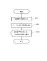
- FIG. 3 is a schematic diagram of a material testing machine in a state in which an upper grip 41 and a lower grip 42 are attached to a testing machine main body instead of the upper grip 11 and the lower grip 12. It is a flowchart which shows the procedure of a jig determination function. It is a flowchart which shows the modification of the procedure of a jig determination function.
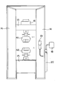
- FIG. 1 is a schematic diagram of a material testing machine of the present invention.
- FIG. 2 is a block diagram illustrating a main control system of the material testing machine according to the present invention.
- This material testing machine arranges a test piece in a test space of a testing machine main body surrounded by a crosshead 13, a table 15, and covers 14 erected on the left and right of the table 15, and performs a material test as a material test. A tensile test is performed.
- the test piece is placed in the test space by being gripped at both ends by the upper grip 11 provided on the crosshead 13 side and the lower grip 12 fixed to the table 15.
- the upper grip 11 and the lower grip 12 are replaceable with respect to the tester main body, and a plurality of types are prepared according to the size and material of the test piece.
- the test force applied to the test piece is detected by a load cell 16 as a force detector disposed on the crosshead 13. Further, the displacement amount between the gauge points attached to the test piece is detected by a displacement meter not shown. Signals from the load cell 16 and the displacement meter are input to the control device 20.
- the control device 20 creates a drive control signal for the motor 31 for raising and lowering the crosshead 13 based on signals from the load cell 16 and the displacement meter.
- the rotation of the motor 31 is controlled, the crosshead 13 moves along the load axis, and various material tests such as a tensile test are executed.
- the control device 20 is constituted by a computer having a memory for storing the operation program of the tester main body and its peripheral devices, and executes various functions according to the program stored in the memory.
- the programs stored in the memory are shown as a set for each function.
- the control unit 20 is connected with a display unit 18, an operation unit 19 used for performing a jog operation for intermittently moving the crosshead 13 by turning on / off a button by an operator, and a moving mechanism 30.
- the display unit 18 is a liquid crystal display device having a touch panel, and functions as an input unit and a display unit according to the present invention.
- the control device 20 takes in the force detected by the load cell 16 and executes data processing. Further, the control device 20 includes a storage unit 23 for storing the test conditions and the weight of the gripper, and a gripper determination unit 25 for determining the type of the gripper based on the output of the load cell 16. In addition, the gripper determination unit 25 includes a determination unit 21 that determines whether the weight of the gripper registered as the test condition matches the weight of the gripper detected by the load cell 16. Further, the control device 20 includes a warning unit 22 that issues a warning to an operator when the weight of the gripping tool is determined to be inconsistent by the determination unit 21.
- FIG. 3 is a flowchart illustrating a procedure when the weight of the gripper is stored in the storage unit 23.
- the operator operates the operation unit 19 to move the crosshead 13 to a position where the test piece can be grasped (step S11).
- the operator inputs the distance L between the gripping tools at this time using the touch panel function of the display unit 18 together with information such as the size, material, and test force of the test piece (step S12).
- the control device 20 reads the absolute position of the crosshead 13 (the height position from the upper surface of the table 15) at this time, and records it in the storage unit 23 as information to be stored in the test condition file together with the input distance L between the grippers. 100 million (step S13).
- the absolute position of the crosshead 13 is determined by the amount of rotation of the motor 31 or the rotary encoder 32 connected to the screw rod in a material testing machine that rotates the screw rod to raise and lower the crosshead 13 as in this embodiment. It is measured by such as.
- the absolute position A as the movement target of the crosshead 13 is determined based on jig information stored as a test condition. And calculate.
- the length C1 of the upper grip 11 in the same direction as the load axis of the connection component, the length C2 of the lower grip 12 in the same direction as the load axis of the connection component, and the distance L between the grippers are shown.
- a difference between the current absolute position of the crosshead 13 and the absolute position A serving as a movement target is calculated as a movement amount of the crosshead 13. Further, the control device 20 recognizes the movable range of the crosshead 13 with the minimum position (C1 + C2 + ⁇ ) where the upper grip 11 and the lower grip 12 do not collide.
- ⁇ represents a minute amount as compared with C1, L, or the like.
- the control device 20 uses the force detected by the load cell 16 at this time as the weight of the upper gripper 11. Then, the information is stored in the storage unit 23 as information to be stored in the test condition file (step S14). In the state where the test piece is not gripped, the force detected by the load cell 16 is the sum of the weights of the connecting parts between the upper grip 11 and the crosshead 13. Is the weight of the upper grip 11.
- the weight of the gripping tool is treated as a part of the test condition by storing it in the same file as the test condition.
- the present invention is not limited to this. If the weight of the gripper can be stored in association with the test condition, for example, a jig information table including the weight of the gripper is stored in the storage unit 23 so that the test condition file can refer to the weight of the gripper. A configuration may be adopted.
- FIG. 4 shows a case where an upper grip 41 and a lower grip 42 which are larger than the upper grip 11 and the lower grip 12 of FIG. 1 are attached to the tester main body. It is a figure for explaining what happens when it moves so that it may become.
- the crosshead 13 moves to the absolute position A
- the upper grip 41 and the lower grip 42 collide, so that the collision can be avoided by using the jig determination function according to the procedure shown in FIG. it can.
- the operator When the operator wants to perform a test under the same conditions as a test performed in the past, the operator selects a test condition file to be tested from the plurality of past test condition files stored in the storage unit 23. It is assumed that the operator selects a test condition file of a tensile test performed when the upper grip 11 and the lower grip 12 are attached, and the distance L between grips is registered. Under these test conditions, when an operator performs an operation of moving the crosshead 13 so that the upper grip 41 and the lower grip 42 hold the test piece so that the distance between the grips is L, the crosshead 13 , To the absolute position A which is the movement target. Then, the upper grip 41 may collide with the lower grip 42. For this reason, in the present invention, a jig determination function for determining whether or not the grip according to the test condition is attached is provided in the control device 20 so as to avoid occurrence of an accident such as collision of the grip. I have to.
- the jig determination function is executed by the CPU executing a program according to the following procedure.
- the control device 20 reads the contents of the test condition file selected from the storage unit 23 into the memory (Step S21). Then, the weight of the upper grip 41 currently detected by the load cell 16 is read (step S22). Thereafter, the weight of the upper grip 41 currently detected by the load cell 16 and the weight of the grip previously stored in the test condition file (the weight of the upper grip 11) are determined by the operation of the determination unit 21. It is determined whether they match (step S23). If the determining unit 21 determines that the weight of the upper grip 41 currently detected by the load cell 16 does not match the weight of the grip previously stored in the test condition file, the warning unit 22 operates A warning is executed (Step S24).
- the warning is performed by displaying a warning message on the display unit 18.
- This warning text may be a content that prompts the operator to replace the gripper, a content that prompts the operator to reset the distance between the grippers, or a display of an error code.
- the warning is not limited to the warning display on the display unit 18, and may be, for example, generating an alarm sound or turning on an alarm lamp.
- the determining unit 21 determines that the weight of the upper grip 41 does not match the weight of the grip previously stored in the test condition file, the warning is issued and the distance between the registered grips is simultaneously determined. May be prohibited.
- the weight of the gripper currently mounted on the crosshead 13 is determined based on the output of the load cell 16. If the weight of the gripper determined by the test conditions does not match the weight of the gripper currently mounted on the crosshead 13, the gripper currently mounted on the crosshead 13 may not be compatible with the test conditions. It is determined that there is. Since the control device 20 can recognize the mismatch between the gripper and the test purpose or the test condition by the operation of the gripper determination unit 25, the controller 20 gives a warning or the like to the operator and incorrectly recognizes the movable range of the crosshead 13. To avoid the operation of the moving mechanism 30 in the above.
- the worker who has received the warning replaces the upper grip 41 and the lower grip 42 with a set of grips (the upper grip 11 and the lower grip 12) that match the test conditions. Then, after the gripper is replaced, the weight of the gripper previously stored in the test condition file and the weight of the upper gripper 11 corresponding to the force detected by the load cell 16 in a state where the test piece is not gripped. If they match (step S23), the control device 20 ends the jig determination. Thereafter, the operator moves the crosshead 13 so that the distance L between the grips registered previously becomes the same, and causes the test piece to be gripped by the upper grip 11 and the lower grip 12.
- the jig and the test conditions are inconsistent, a warning is issued to the worker, and the worker replaces the jig to avoid collision between the upper grip 41 and the lower grip 42.
- the absolute position A of the crosshead 13 is set to the absolute position so that the distance between the grips is set to L.
- An operation of automatically changing to A ' is also possible. Even in that case, collision between the upper and lower grips can be avoided.
- FIG. 6 is a flowchart showing a modification of the procedure of the jig determination function.
- the control device 20 reads the contents of the test condition file selected from the storage unit 23 into the memory (Step S31). Then, the weight of the upper grip 41 currently detected by the load cell 16 is read (step S32). Then, the weight is displayed on the display unit 18 (step S33).
- This display is preferably displayed together with information such as test pieces on an input screen when an operator creates test conditions. That is, when the test information is input, the current weight of the grip is displayed, so that the operator can easily notice the mismatch between the test condition and the attached grip.
- the content displayed on the display unit 18 is not limited to the weight of the grip, but may be other grip information such as a model name or a rated capacity of the grip that can be specified from the weight.
- the functions of the determination unit 21 and the warning unit 22 described above can be omitted. That is, information on the gripper currently mounted on the crosshead 13 determined based on the output of the load cell 16 is displayed together with the test conditions on the display unit 18 to determine which jig is currently mounted on the tester main body. It is sufficient if the information is shown to the operator so that the operator can positively recognize the mismatch with the test purpose or the test condition.
- the content to be displayed on the display unit 18 may be any content that can alert the worker to the grip, and does not need to be a warning display.
- the moving member is the crosshead 13
- the fixed member is the table 15
- the moving mechanism 30 is the pair of screw rods and the motor 31, and the load cell 16, which is a force detector, is disposed on the crosshead 13 side and is grasped upward.
- the tester is configured to detect the weight of the tool, but is not limited to this. That is, it is only necessary that the force detector can detect the weight of one of the pair of grips.
- the moving mechanism is a hydraulic or pneumatic actuator
- the moving member is a rod of the actuator
- the actuator is arranged in a table
- a lower grip is connected to a rod that penetrates the upper surface of the table
- a load cell as a force detector is connected.
- the present invention can also be applied to a test machine configuration in which the weight of the upper grip is detected by being arranged on the side of a cross yoke which is a fixing member provided on a support. Further, in the present invention, the load cell 16 detects the weight of the upper grip, but the load cell may be connected to the lower grip to detect the weight of the lower grip. If the test piece is not gripped, the force applied to the load cell is the weight of the lower grip and the connecting part, which is the same as that of the upper grip.
- the expression that the gripper is relatively moved means that at least one of the pair of grippers is moved, and that the gripper on which the force detector is mounted is moved. It is not limited to meaning.
- the gripper determination unit in the present invention determines the type of each gripper based on the output of the force detector, that is, the weight of the gripper.
- Many types of gripping tools are used depending on their capacity, size, type, and the like.
- the weight of each gripping item is a substantially constant value determined by a design value for each type. Since the grip does not set the weight as the target value of the design, it is almost accidental that one grip becomes the weight, but the present invention uses this weight as an index to determine the grip. It is a feature of. If two types of grips happen to have approximately the same weight by chance, if the weight is made different by adding a weight to one of the grips, it is suitable for applying the present invention. Becomes
- the grips are an important component of the material testing machine, they are often replaced and used, so automatically knowing which grips are currently installed can be a challenge when performing a material test. Is useful in many situations. Moreover, a special mechanism (for example, a CCD camera or the like in the above cited reference 1) is not required for the discrimination, and the discrimination based on the output of a force detector almost always used in a material testing machine is a major point in terms of a simple configuration. There are advantages.
- a database of the grippers used for the tester of the present invention can be obtained.
- the database can be searched using the weight of the gripper as a key, and it is desirable that the database include the model name, the size of the outer shape, the length in the load axis direction, and the like of the gripper.
- the database for example, it is possible to display to the operator what the model name of the gripper currently mounted on the testing machine is, and by extension, to be attached to the material to be tested. It is possible to indicate whether the gripper is suitable for its use.
- the operator can grasp the distance between the grippers.
- the absolute position A of the crosshead 13 is automatically set only by designating the distance L, and there is no danger of collision between the upper and lower grips.
Landscapes
- Physics & Mathematics (AREA)
- Health & Medical Sciences (AREA)
- Life Sciences & Earth Sciences (AREA)
- Chemical & Material Sciences (AREA)
- Analytical Chemistry (AREA)
- Biochemistry (AREA)
- General Health & Medical Sciences (AREA)
- General Physics & Mathematics (AREA)
- Immunology (AREA)
- Pathology (AREA)
- Investigating Strength Of Materials By Application Of Mechanical Stress (AREA)
Abstract
Selon la présente invention, un dispositif de commande (20) comprend une unité de mémoire (23) permettant de mémoriser des conditions de test et un poids d'outil de préhension, une unité de détermination (21) permettant de déterminer si le poids d'outil de préhension enregistré en tant que condition de test correspond au poids d'outil de préhension détecté par une cellule de pesage (16), et une unité d'avertissement (22) permettant d'avertir un technicien si l'unité de détermination (21) détermine que les poids d'outil de préhension ne correspondent pas. L'avertissement rend plus facile pour un technicien de vérifier si un outil de préhension qui correspond aux conditions de test est fixé.
Priority Applications (2)
| Application Number | Priority Date | Filing Date | Title |
|---|---|---|---|
| PCT/JP2018/032330 WO2020044530A1 (fr) | 2018-08-31 | 2018-08-31 | Appareil de test de matériau |
| JP2020539979A JP6958742B2 (ja) | 2018-08-31 | 2018-08-31 | 材料試験機 |
Applications Claiming Priority (1)
| Application Number | Priority Date | Filing Date | Title |
|---|---|---|---|
| PCT/JP2018/032330 WO2020044530A1 (fr) | 2018-08-31 | 2018-08-31 | Appareil de test de matériau |
Publications (1)
| Publication Number | Publication Date |
|---|---|
| WO2020044530A1 true WO2020044530A1 (fr) | 2020-03-05 |
Family
ID=69643999
Family Applications (1)
| Application Number | Title | Priority Date | Filing Date |
|---|---|---|---|
| PCT/JP2018/032330 Ceased WO2020044530A1 (fr) | 2018-08-31 | 2018-08-31 | Appareil de test de matériau |
Country Status (2)
| Country | Link |
|---|---|
| JP (1) | JP6958742B2 (fr) |
| WO (1) | WO2020044530A1 (fr) |
Citations (5)
| Publication number | Priority date | Publication date | Assignee | Title |
|---|---|---|---|---|
| JPS618859A (ja) * | 1984-06-22 | 1986-01-16 | 松下電器産業株式会社 | 端子台 |
| JPH03142179A (ja) * | 1989-10-25 | 1991-06-17 | Toshiba Corp | マスタスレーブ制御装置 |
| JP2002365188A (ja) * | 2001-06-05 | 2002-12-18 | Shimadzu Corp | 材料試験機 |
| JP2007024784A (ja) * | 2005-07-20 | 2007-02-01 | Shimadzu Corp | 材料試験機 |
| JP2013250219A (ja) * | 2012-06-04 | 2013-12-12 | Shimadzu Corp | 材料試験機 |
Family Cites Families (4)
| Publication number | Priority date | Publication date | Assignee | Title |
|---|---|---|---|---|
| JPH0742116Y2 (ja) * | 1990-11-01 | 1995-09-27 | 株式会社オリエンテック | 引張試験機用チャック |
| JP4244710B2 (ja) * | 2003-06-02 | 2009-03-25 | 株式会社島津製作所 | 材料試験機 |
| JP4207674B2 (ja) * | 2003-06-09 | 2009-01-14 | 株式会社島津製作所 | 材料試験機 |
| JP2016205824A (ja) * | 2015-04-15 | 2016-12-08 | 株式会社島津製作所 | 材料試験機 |
-
2018
- 2018-08-31 WO PCT/JP2018/032330 patent/WO2020044530A1/fr not_active Ceased
- 2018-08-31 JP JP2020539979A patent/JP6958742B2/ja active Active
Patent Citations (5)
| Publication number | Priority date | Publication date | Assignee | Title |
|---|---|---|---|---|
| JPS618859A (ja) * | 1984-06-22 | 1986-01-16 | 松下電器産業株式会社 | 端子台 |
| JPH03142179A (ja) * | 1989-10-25 | 1991-06-17 | Toshiba Corp | マスタスレーブ制御装置 |
| JP2002365188A (ja) * | 2001-06-05 | 2002-12-18 | Shimadzu Corp | 材料試験機 |
| JP2007024784A (ja) * | 2005-07-20 | 2007-02-01 | Shimadzu Corp | 材料試験機 |
| JP2013250219A (ja) * | 2012-06-04 | 2013-12-12 | Shimadzu Corp | 材料試験機 |
Also Published As
| Publication number | Publication date |
|---|---|
| JPWO2020044530A1 (ja) | 2021-08-10 |
| JP6958742B2 (ja) | 2021-11-02 |
Similar Documents
| Publication | Publication Date | Title |
|---|---|---|
| US8863583B2 (en) | Material testing system | |
| CN101226387B (zh) | 控制装置 | |
| CN112512762B (zh) | 异常判定装置和异常判定方法 | |
| JP2015196231A (ja) | ねじ締付け装置 | |
| JP7114885B2 (ja) | 作業現場監視装置およびプログラム | |
| EP3521801A1 (fr) | Procédé d'évaluation de résultat de test et testeur de matériau | |
| EP3750677A1 (fr) | Machine pour le travail de pieces de bois fournies avec un dispositif de ramassage et methode d operation correspondante | |
| CN109682302A (zh) | 一种轴类零件高精度全自动测量设备 | |
| TWI752989B (zh) | 凸緣的鎖緊管理方法、鎖緊管理系統、鎖緊管理程式及鎖緊管理裝置 | |
| CN209992064U (zh) | 一种电子天平自动检定装置 | |
| CN103383240A (zh) | 机器视觉二维检测平台装置 | |
| WO2020044530A1 (fr) | Appareil de test de matériau | |
| CN105738747A (zh) | 贴片电阻检测方法、系统及装置 | |
| CN101825538B (zh) | 螺丝锁附可靠度的检测方法 | |
| JP6471684B2 (ja) | 硬さ試験機 | |
| JPH06104546B2 (ja) | 昇降機の点検整備管理装置 | |
| CN104176643B (zh) | 一种起重机主副臂工况的选择方法、控制装置及起重机 | |
| CN115689525A (zh) | 一种起重机维护方法、系统及电子设备 | |
| TWI445967B (zh) | 電子元器件的物理應力自動測量系統及方法 | |
| JP5999979B2 (ja) | 試験装置 | |
| JP2002250682A (ja) | 材料試験機 | |
| US20240280979A1 (en) | Abnormality processing apparatus, network system, and method for providing procedure with respect to abnormality having occurred in robot system | |
| KR102030184B1 (ko) | 공작기계의 작업 원점 자동 설정 장치 및 방법 | |
| KR20230062135A (ko) | 딥 러닝을 기반으로 하는 광학적 특징 인식 및 전류 측정을 통한 중량정보 인식 시스템 및 방법, 및 동 방법을 컴퓨터에서 실행하기 위한 컴퓨터 프로그램이 기록된, 컴퓨터 판독 가능한 기록 매체 | |
| JP2003080395A (ja) | パス間温度管理装置 |
Legal Events
| Date | Code | Title | Description |
|---|---|---|---|
| 121 | Ep: the epo has been informed by wipo that ep was designated in this application |
Ref document number: 18932050 Country of ref document: EP Kind code of ref document: A1 |
|
| ENP | Entry into the national phase |
Ref document number: 2020539979 Country of ref document: JP Kind code of ref document: A |
|
| NENP | Non-entry into the national phase |
Ref country code: DE |
|
| 122 | Ep: pct application non-entry in european phase |
Ref document number: 18932050 Country of ref document: EP Kind code of ref document: A1 |