WO2020045065A1 - Connecteur mobile - Google Patents
Connecteur mobile Download PDFInfo
- Publication number
- WO2020045065A1 WO2020045065A1 PCT/JP2019/031708 JP2019031708W WO2020045065A1 WO 2020045065 A1 WO2020045065 A1 WO 2020045065A1 JP 2019031708 W JP2019031708 W JP 2019031708W WO 2020045065 A1 WO2020045065 A1 WO 2020045065A1
- Authority
- WO
- WIPO (PCT)
- Prior art keywords
- housing
- movable
- connection
- contact
- movable connector
- Prior art date
- Legal status (The legal status is an assumption and is not a legal conclusion. Google has not performed a legal analysis and makes no representation as to the accuracy of the status listed.)
- Ceased
Links
Images







Classifications
-
- H—ELECTRICITY
- H01—ELECTRIC ELEMENTS
- H01R—ELECTRICALLY-CONDUCTIVE CONNECTIONS; STRUCTURAL ASSOCIATIONS OF A PLURALITY OF MUTUALLY-INSULATED ELECTRICAL CONNECTING ELEMENTS; COUPLING DEVICES; CURRENT COLLECTORS
- H01R12/00—Structural associations of a plurality of mutually-insulated electrical connecting elements, specially adapted for printed circuits, e.g. printed circuit boards [PCB], flat or ribbon cables, or like generally planar structures, e.g. terminal strips, terminal blocks; Coupling devices specially adapted for printed circuits, flat or ribbon cables, or like generally planar structures; Terminals specially adapted for contact with, or insertion into, printed circuits, flat or ribbon cables, or like generally planar structures
- H01R12/70—Coupling devices
- H01R12/91—Coupling devices allowing relative movement between coupling parts, e.g. floating or self aligning
-
- H—ELECTRICITY
- H01—ELECTRIC ELEMENTS
- H01R—ELECTRICALLY-CONDUCTIVE CONNECTIONS; STRUCTURAL ASSOCIATIONS OF A PLURALITY OF MUTUALLY-INSULATED ELECTRICAL CONNECTING ELEMENTS; COUPLING DEVICES; CURRENT COLLECTORS
- H01R13/00—Details of coupling devices of the kinds covered by groups H01R12/70 or H01R24/00 - H01R33/00
- H01R13/62—Means for facilitating engagement or disengagement of coupling parts or for holding them in engagement
- H01R13/629—Additional means for facilitating engagement or disengagement of coupling parts, e.g. aligning or guiding means, levers, gas pressure electrical locking indicators, manufacturing tolerances
- H01R13/631—Additional means for facilitating engagement or disengagement of coupling parts, e.g. aligning or guiding means, levers, gas pressure electrical locking indicators, manufacturing tolerances for engagement only
-
- H—ELECTRICITY
- H01—ELECTRIC ELEMENTS
- H01R—ELECTRICALLY-CONDUCTIVE CONNECTIONS; STRUCTURAL ASSOCIATIONS OF A PLURALITY OF MUTUALLY-INSULATED ELECTRICAL CONNECTING ELEMENTS; COUPLING DEVICES; CURRENT COLLECTORS
- H01R13/00—Details of coupling devices of the kinds covered by groups H01R12/70 or H01R24/00 - H01R33/00
- H01R13/62—Means for facilitating engagement or disengagement of coupling parts or for holding them in engagement
- H01R13/639—Additional means for holding or locking coupling parts together, after engagement, e.g. separate keylock, retainer strap
Definitions
- the disclosure according to the present application relates to a movable connector having a floating function.
- the connector 10 includes a fixed housing 11 mounted on a substrate, a movable housing 12 housed in the fixed housing 11, and a terminal 13 having a movable piece 13b that displaceably supports the movable housing 12 inside the fixed housing 11.
- the movable housing 12 is provided with an insertion hole 12e on a surface facing the substrate.
- the object to be connected In order to electrically connect an object to be connected (for example, a pin terminal of an electric element) to the connector 10, the object to be connected is inserted into the insertion hole 12 e from the back of the substrate, and the object to be connected is Conductive contact is made with the contact portion 13e.
- an object to be connected for example, a pin terminal of an electric element
- the contact pressure between the contact portion 13e and the object to be connected is reduced, for example, when the connector 10 is subjected to vibration in an environment of use, they will make fine sliding contact. Then, the plating on the surface of the object to be connected peels off due to fine sliding wear, and it becomes difficult to maintain stable conductive contact.
- the movable connector including the bottom entry type such as the connector 10 the easiness of the multi-pole connection and the stability of the conductive contact of each contact portion are in conflicting requirements.
- An object of the present application is to improve the ease of fitting connection and the stability of conductive connection for a movable connector.
- one embodiment disclosed in the present application includes a first housing fixed to a substrate, a second housing having a connection chamber into which an object to be connected is inserted, and a second housing arranged in the connection chamber and including the connection object.
- a movable connector including a terminal having a contact portion that makes conductive contact with an object and a movable portion that supports the second housing so as to be displaceable with respect to the first housing, the object to be connected to the connection chamber;
- a pressing member that presses the second housing in a direction intersecting with the insertion direction of the second housing. When the second housing is pressed by the pressing member, the second housing moves relative to the connection object in the cross direction.
- the contact portion is displaced and makes a pressure contact while increasing a contact pressure on the connection object by the relative displacement of the second housing.
- the second housing which is displaceably supported by the movable portion, is displaced with respect to the connection target arranged in the connection chamber of the first housing and the second housing. That is, when the pressing member presses the second housing in the cross direction, the second housing is displaced.
- the contact portion of the terminal is disposed in the connection chamber of the second housing that is displaced. For this reason, with the displacement of the second housing, the contact portion of the terminal approaches the connection object arranged in the connection chamber, and makes a pressure contact while increasing the contact pressure on the connection object.
- the misalignment is caused by the displacement of the second housing supported by the movable portion. Can be absorbed.
- connection target when the connection target is arranged in the second housing, the connection target can be prevented from receiving the pressing force received from the contact portion at the time of the fitting connection, or the pressing force can be reduced.
- the arrangement structure of the object to be connected to the connection chamber can be configured as a LIF (Light Insertion Force) structure with a small insertion force or a ZIF (Zero Insertion Force) structure with a zero insertion force. Therefore, in the above embodiment, the connection target can be easily inserted into the connection chamber.
- the pressing member is fixed to the second housing by being pushed into the second housing, and the fitting connection state in which the contact portion is in press contact with the connection object is provided. Can be configured to hold.
- the second housing by pressing the pressing member into the second housing, the second housing can be easily displaced, and the contact portion can be pressed against the connection target. Further, since the pressing member is fixed to the second housing by the pushing operation, the fitting and connected state in which the contact portion has pressed and contacted the connection target can be reliably maintained. Therefore, according to this embodiment, the fitting connection between the movable connector and the connection target can be easily performed.
- the pressing member may be configured to include an insertion pressing portion that is inserted between the connection target disposed in the connection chamber and an inner surface of the second housing to press the second housing.
- the insertion pressing portion is inserted while being sandwiched between the connection object and the inner surface of the second housing. Therefore, the insertion pressing portion can reliably press the inner surface of the second housing, and the second housing can be displaced reliably by the pushing operation.
- the insertion pressing portion may be configured to have an arrangement concave portion on the surface facing the connection object, extending along the insertion direction and arranging the connection object.
- connection target is positioned in the arrangement concave portion of the insertion pressing portion. For this reason, when the operation of pushing the pressing member into the second housing is performed, the insertion pressing portion can be inserted while suppressing the displacement of the connection target.
- Some embodiments disclosed in the present application can be further configured to include a conduction detection terminal that is disposed on the pressing member and that is electrically connected to the connection target disposed in the connection chamber.
- connection target is brought into conductive contact with the conduction detection terminal, whereby it is possible to confirm that the connection target is properly fitted and connected to the movable connector.
- the conduction detection terminal can be configured to be arranged in the arrangement recess.
- the connection target can be reliably brought into conductive contact with the conduction detection terminal.
- the connection object since the connection object receives the pressing contact of the contact portion and makes conductive contact with the conduction detection terminal arranged in the arrangement concave portion, the conduction between the connection object and the contact portion can be reliably detected.
- the conduction detecting terminal can be configured to have an external contact portion disposed on an outer surface of the pressing member.
- the inspection device since the external contact portion of the conduction detection terminal is arranged on the outer surface of the pressing member, the inspection device can be brought into contact with the external contact portion from outside the pressing member. Therefore, according to this embodiment, the continuity test can be easily performed.
- the pressing member is further locked to the pressing member at a pre-fitting position where the pressing member does not press the second housing, and It can be configured to have a holding spring for restricting displacement toward the housing.
- Some embodiments disclosed in the present application further include a substrate fixing member for fixing the first housing to the substrate, wherein the substrate fixing member is provided with the holding spring and the substrate. And a substrate fixing portion for fixing the substrate.
- the substrate fixing member for fixing the first housing to the substrate has the substrate fixing portion and the holding spring, the substrate fixing member is used for fixing to the substrate and the pressing member for the second housing is used. Can also be used to hold the combination position. Therefore, an increase in the number of components of the movable connector can be suppressed.
- fitting connection is easy, and stable conductive connection can be ensured.
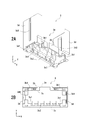
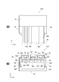
- FIG. 2 is an exploded perspective view including a front surface, a left side surface, and a flat surface of the movable connector according to the embodiment. It is a figure which shows the fixed housing of FIG. 1, 2A is a perspective view including the front, the left side, and the bottom, and 2B is a bottom view. 3A is a plan view showing the movable housing of FIG. 1, and FIG. 3B is a bottom view. FIG. 4 is a view showing the operation housing of FIG. 1, wherein 4A is a rear view and 4B is a bottom view.
- FIG. 2 is a perspective view including a front surface, a left side surface, and a flat surface of the board connection terminal of FIG. 1.
- FIG. 1 is a perspective view including a front surface, a left side surface, and a flat surface of the board connection terminal of FIG. 1.
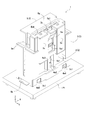
- FIG. 2 is a perspective view including a front surface, a left side surface, and a plane showing a state where the movable connector of FIG. 1 is mounted on a substrate.
- the top view of FIG. FIG. 8 is a sectional view taken along line VIII-VIII of FIG. 7.
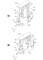
- 9A is a perspective view including a front surface, a left side surface, and a plane showing a fitting process of the movable housing and the operation housing
- 9A is a perspective view before fitting and fixing
- 9B is a perspective view after fitting and fixing.
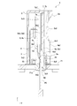
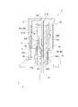
- FIG. 8 is a cross-sectional view corresponding to line XX of FIG. 7 illustrating a fitting connection process between the movable connector and the connection target. Sectional drawing which shows the fitting connection process following FIG.
- FIG. 8 is a cross-sectional view corresponding to line XX of FIG. 7 showing a fitting connection process in a state where the movable connector and the connection target are displaced.
- FIG. 14 is an exemplary sectional view showing the fitting / connection process following FIG. 13;
- FIG. 15 is an exemplary sectional view showing the fitting / connection process following FIG. 14;
- the movable connector 1 is mounted on the board P1 shown in FIG.
- a hole P1a is formed through the substrate P1, and the movable housing 4 is inserted therethrough.
- the pin terminal P2 as a “connection object” is arranged inside the movable housing 4 from below the substrate P1.
- the board P1 and the pin terminal P2 are non-movable members that do not move in the XY directions when the movable connector 1 and the pin terminal P2 are fitted and connected.
- the arrangement direction (left-right direction) of the plurality of terminals 6 of the movable connector 1 shown in FIG. 1 is defined as an X direction
- the depth direction (front-rear direction) of the movable connector 1 is defined as a Y direction
- the height direction (vertical direction) of the movable connector 1 will be described as a Z direction.
- the terms “first” and “second” described in the present specification and the claims are used to distinguish different components, and are used in order to indicate a particular order or priority. Not used.
- the movable connector 1 includes a housing 2 made of a molded body of hard resin.
- the housing 2 includes a fixed housing 3 as a “first housing”, a movable housing 4 as a “second housing”, and an operation housing 5 as a “pressing member”.
- a terminal 6 made of a metal piece is fixed to the fixed housing 3 and the movable housing 4.
- a conduction detection terminal 7 is attached to the operation housing 5.
- a board fixing member 8 is attached to the fixed housing 3.
- the fixed housing 3 is mounted on the board P1.
- the fixed housing 3 is formed of a rectangular frame-shaped resin molded body.
- the fixed housing 3 has a cylindrical peripheral wall 3a.
- the peripheral wall 3a has a front wall 3b, a rear wall 3c, and left and right side walls 3d.
- An accommodation space 3e is formed inside the fixed housing 3, in which the movable housing 4, the operation housing 5, and the terminals 6 are arranged.
- the inner peripheral surface of the peripheral wall 3a is an opening that can be inserted into the movable housing 4 with an interval therebetween.
- left and right locking recesses 3b1 are formed to lock locking projections 4a4 of the movable housing 4 described later in the X and Z directions. Similar locking recesses 3c1 are formed on the left and right sides of the rear wall 3c.
- a plurality of fixed side terminal fixing portions 3c2 arranged in the X direction are formed on the rear wall 3c, and the fixed housing fixing portions 6b of the terminals 6 are press-fitted and held therein.
- Board fixing member fixing portions 3d1 for press-fitting the substrate fixing member 8 are formed in the left and right side walls 3d.
- a locking groove 3d2 extending along the height direction is formed penetrating the side wall 3d. The locking protrusion 8c of the board fixing member 8 fixed to the fixing portion 3d1 for the board fixing member enters the locking groove 3d2, and locks downward in the Z direction.
- the movable housing 4 is formed of a rectangular frame-shaped resin molded body.
- the movable housing 4 has a front wall 4a, a rear wall 4b, left and right side walls 4c, and a bottom wall 4d.
- a lock recess 4a1 into which a lock arm 5a of the operation housing 5 described later is inserted is formed in the front wall 4a.
- the lock recess 4a1 is formed with a lock hole 4a2 into which the lock protrusion 5a1 of the lock arm 5a enters.
- a lock stopper 4a3 is formed in the lock hole 4a2.
- the lock protrusion 5a1 is engaged with the lock protrusion 4a3 upward in the Z direction to prevent the operation housing 5 from being detached from the movable housing 4.
- the left and right locking projections 4a4 are formed on the front wall 4a so as to protrude forward.
- engagement guide protrusions 4a5 are formed on the left and right of the upper end of the front wall 4a so as to protrude forward, and guide the displacement caused by the pushing operation of the operation housing 5 to be described later. To keep out.
- a plurality of terminal arrangement grooves 4b1 extending in the Z direction are formed on the inner surface of the rear wall 4b so as to be arranged in the X direction.
- a movable housing fixed portion 6d of the terminal 6 described later and a contact portion 6e are arranged in the terminal arrangement groove 4b1. Since each of the terminal arrangement grooves 4b1 is formed in a concave shape, the adjacent contact portions 6e are not electrically connected to each other.
- the movable terminal fixing portion 4b2 is formed in each terminal arrangement groove 4b1, and the movable housing fixing portion 6d of the terminal 6 is press-fitted and held therein.
- a locking projection 4b3 that locks in the X direction and the Z direction with respect to the locking recess 3c1 of the fixed housing 3 is formed on the rear wall 4b so as to project rearward.
- the side wall 4c is formed as a flat plate piece extending in the Z direction.
- the side wall 4c is arranged along an insertion guide portion 5e3 formed on the inner surface of the operation housing 5 described later, and functions as a guide when the operation housing 5 is pushed.
- a plurality of insertion holes 4d1 for inserting the pin terminal P2 as a “connection object” are formed in the bottom wall 4d so as to be arranged in the X direction.
- a guide inclined surface 4d2 for guiding the pin terminal P2 is formed on the entrance side of the insertion hole 4d1.
- connection chamber 4e The inside of the movable housing 4 as described above is formed as a connection chamber 4e. That is, the pin terminal P2 is inserted into the connection chamber 4e from the insertion hole 4d1.
- the operation housing 5 as a "pressing member” has a lock arm 5a, an insertion pressing portion 5b, a cover portion 5c, an engagement guide portion 5d, left and right side walls 5e, a rear wall 5f (FIG. 4A), and a top wall 5g. I have.
- the lock arm 5a is formed integrally with the contact surface 5b1 on the front side of the insertion pressing portion 5b.
- the lock arm 5a protrudes forward from the contact surface 5b1, and is formed as a cantilevered elastic piece extending in the Z direction.
- the lock arm 5a is formed with the lock protrusion 5a1 described above.
- the lock projection 5a1 is locked in the Z direction with respect to the above-mentioned first retaining locking portion 4a3 of the movable housing 4, thereby preventing the operation housing 5 from falling out of the movable housing 4.
- the insertion pressing portion 5b is formed in a plate shape, and has a contact surface 5b1 on the front side.
- a plurality of arrangement recesses 5b2 extending in the Z direction are formed side by side in the X direction on the rear side opposite to the pin terminal P2 on the opposite side.
- the upper end of the arrangement recess 5b2 extends to an opening 5g1 that penetrates the top wall 5g.
- an insertion portion 5b3 for the pin terminal P2 is formed at the lower end of the arrangement recess 5b2.
- the insertion portion 5b3 is provided at a position extending above the insertion hole 4d1 of the movable housing 4 in the Z direction.
- the cover portion 5c is formed by a concave wall projecting forward in the Y direction from the left and right side walls 5e, and an engagement guide portion 5d is disposed inside the concave wall. That is, the cover portion 5c is located at the upper end of the pair of side wall portions 5c1 extending in the Y direction, the front wall portion 5c2 connecting the pair of side wall portions 5c1 in the X direction, and the pair of side wall portions 5c1 and the front wall portion 5c2. And an upper wall portion 5c3. A gap is formed between the pair of side wall portions 5c1 and the insertion pressing portion 5b, and the front wall 4a of the movable housing 4 is inserted into the gap.
- the engagement guide portion 5d is protected from the outside by being covered by the cover portion 5c.
- the engagement guide portion 5d is formed as a U-shaped clip extending downward in the Z direction from the upper wall portion 5c3 of the cover portion 5c.
- the engagement guide portion 5d has a pair of elastic arms 5d1 and a second retaining locking portion 5d2 connecting the lower ends of the pair of elastic arms 5d1.
- the engagement guide projection 4a5 of the movable housing 4 is inserted between the pair of elastic arms 5d1. Therefore, when the operation housing 5 is pushed into the movable housing 4, the pair of elastic arms 5 d 1 move while being guided by the engagement guide protrusions 4 a 5 of the movable housing 4.
- a first locking receiving portion 5e1 that locks with a holding spring 8b of the substrate fixing member 8 described later is formed on the side wall 5e.
- the holding spring 8 b locks the first locking receiving portion 5 e 1 so as to press it from above. . Therefore, it is possible to prevent the operation housing 5 from rattling with respect to the movable housing 4 in the Z direction, thereby causing a problem such as a connection failure.
- Below the first lock receiving portion 5e1 there is formed a second lock receiving portion 5e2 which also locks with the holding spring 8b.
- the second lock receiving portion 5e2 is formed as a recess. As shown in FIG.
- the rear wall 5f is arranged so as to fit into the concave portion 3f formed by the pair of side walls 3d and the rear wall 3c of the fixed housing 3 in a fitting connection state in which the operation housing 5 is pushed in and fitted and connected to the movable housing 4. Is done.
- the operation housing 5 when the operation housing 5 is removed from the movable housing 4, the operation housing 5 can be held by using the rear wall 5f as a rear grip portion.
- the front gripping portion may be the lock arm 5a and the cover 5c.
- the top wall 5g is located on the upper surface of the operation housing 5.
- the opening 5g1 is formed in the top wall 5g as described above. As shown in FIG. 7, the opening 5g1 is used to determine whether or not the pin terminal P2 is appropriately arranged with respect to the contact portion 6e of the terminal 6 and the conduction detection terminal 7 by performing an appearance inspection based on a captured image or the like. Are formed as inspection openings.
- a plurality of terminals 6 are arranged in parallel with the movable connector 1 along the X direction.
- Each terminal 6 has the same shape. Specifically, as shown in FIG. 5, the terminal 6 has a board connecting portion 6a, a fixed portion 6b for a fixed housing, a movable portion 6c, a fixed portion 6d for a movable housing, and a contact portion 6e.
- the board connection portion 6a is electrically connected to a circuit on the board P1 by being fixed to the board P1 by a soldering portion.
- the fixed housing fixing portion 6b is pressed into and held by the fixed terminal fixing portion 3c2 of the fixed housing 3. Thereby, one end of the terminal 6 is fixed to the fixed housing 3.
- the movable housing fixing portion 6d is pressed into and held by the movable terminal fixing portion 4b2 of the movable housing 4. As a result, the other end of the terminal 6 is fixed to the movable housing 4.
- the contact portion 6e has a front contact portion 6e1 and a rear contact portion 6e2.
- the front contact portion 6e1 has a pair of front elastic arms 6e3 extending from the movable housing fixing portion 6d, and a front contact portion 6e4 provided at the distal ends of the pair of front elastic arms 6e3.
- the rear contact portion 6e2 is provided at the distal end of the pair of rear elastic arms 6e5 extending between the movable housing fixing portion 6d and the pair of front elastic arms 6e3 and between the pair of front elastic arms 6e3.
- a rear contact portion 6e6 arranged at
- the contact portion 6e of this embodiment has a multipoint contact structure in which the front contact portion 6e1 and the rear contact portion 6e2 contact the pin terminal P2. For this reason, even if one of the conductive contact structures has a defect, the other conductive contact structure can make normal conductive contact, so that the reliability of the conductive connection can be improved.
- the front contact portion 6e1 first makes sliding contact with the pin terminal P2, and then the rear contact portion 6e2 makes sliding contact. For this reason, the rear contact portion 6e2 can be brought into conductive contact with the pin terminal P2 in a state where the foreign matter attached to the pin terminal P2 is removed by the front contact portion 6e1. This also increases the reliability of the conductive connection.
- the contact portion 6e has the multipoint contact structure as described above, the front contact portion 6e1 and the rear contact portion 6e2 contact at two points separated from each other in the longitudinal direction of the rod-shaped pin terminal P2.
- the pin terminal P2 makes point contact with the conduction detection terminal 7 in a state where the pin terminal P2 is inclined obliquely with the contact point as a fulcrum, and the stable conduction contact of the pin terminal P2 is achieved. The posture may not be maintained.
- the contact portion 6e has a two-point contact structure, the pin terminal P2 can be brought into conductive contact straight along the conduction detection terminal 7.
- the movable portion 6c is formed as a spring piece that supports the movable housing 4 so as to be displaceable in the XYZ directions with respect to the fixed housing 3.
- the movable portion 6c has an outer vertical piece 6c1, a folded portion 6c2, and an inner vertical piece 6c3, and is formed in an inverted U shape as a whole. Thereby, the movable portion 6c can also displace the movable housing 4 in a direction (X direction) intersecting the insertion direction (Z direction) of the pin terminal P2 into the connection chamber 4e.
- the conduction detection terminal 7 is formed of a flat conductive metal, is disposed in the operation housing 5, and is conductively connected to the pin terminal P2 disposed in the connection chamber 4e.
- the continuity detection terminal 7 has an internal contact portion 7a arranged in the groove of the arrangement recess 5b2 of the operation housing 5.
- the thickness of the internal contact portion 7a is smaller than the groove depth of the arrangement recess 5b2, and is arranged so as not to protrude outside from the arrangement recess 5b2.
- the continuity detecting terminal 7 has an external contact portion 7b arranged on the outer surface of the operation housing 5. Since the external contact portion 7b is arranged so as to be exposed inside the opening 5g1 of the operation housing 5, the inspection device can be brought into conductive contact with the external contact portion 7b. Therefore, the continuity test can be easily performed.
- the substrate fixing member 8 is formed of a flat conductive metal, and fixes the fixed housing 3 to the substrate P1.
- the substrate fixing member 8 has a substrate fixing portion 8a to be soldered to the substrate P1, a holding spring 8b, and a locking projection 8c.
- the holding spring 8b locks the first locking receiving portion 5e1 from above in the fitted connection state in which the operating housing 5 is pushed in and fitted and connected to the movable housing 4.
- the holding spring 8b holds the unfitted connection state before the operation housing 5 is pushed into the movable housing 4 by being pressed against the second lock receiving portion 5e2.
- the locking projection 8c is arranged inside the locking groove 3d2 of the side wall 3d of the fixed housing 3.
- the lock arm 5a is pushed in from the fitted and connected state shown in FIG. 9B to release the lock, and the operation housing 5 is pulled up with respect to the movable housing 4, the fixed housing 3 is similarly pulled up.
- the locking groove 3d2 abuts on the locking projection 8c, the fixed housing 3 can be held so as not to be pulled up.
- the movable connector 1 is mounted on the board P1.
- the movable connector 1 shown in the figure shows an unfitted connection state before performing a pushing operation of pushing the operation housing 5 into the movable housing 4.
- the pin terminal P2 is arranged in the connection chamber 4e from the unfitted connection state. This arrangement is performed by either the movement of the pin terminal P2, the movement of the movable connector 1 and the board P1, or the movement of both.
- the board P1 and the pin terminal P2 are non-movable members that do not move in the XY directions when fitted and connected to the movable connector 1.
- the board P1 and the pin terminal P2 are fixed to a mounting object that does not move with each other. Therefore, it is ideal that the insertion axis of the pin terminal P2 and the movable housing 4 match at the initial position before the fitting connection.
- the mounting object of the board P1 and the pin terminal P2 is displaced, their insertion axes are displaced from each other.
- the movable connector 1 can be displaced by the operation of pressing the operation housing 5 at the time of fitting connection, and the displacement of the insertion shaft can be absorbed. Therefore, the movable connector 1 and the pin terminal P2 can be fitted and connected in a state where the displacement of the insertion shaft between the pin terminal P2 and the movable housing 4 is absorbed.
- this point will be described.
- the pin terminal P2 is disposed in the insertion hole 4d1 of the movable housing 4. At this time, the pin terminal P2 is arranged along the hole surface of the insertion hole 4d1 on the contact portion 6e side.
- the pin terminal P2 presses the contact portion 6e leftward in the figure as shown in FIG.
- the contact portion 6e is not elastically deformed, or is slightly elastically deformed.
- the contact portion 6e does not generate a contact pressure on the pin terminal P2 or is in contact with the pin terminal P2 with a slight contact pressure. Therefore, the insertion force of the pin terminal P2 causes the movable portion 6c to elastically deform leftward in the drawing. That is, the spring constant of the movable portion 6c is lower than the spring constant of the contact portion 6e, and when the pressing force of the pin terminal P2 acts, the movable portion 6c is elastically deformed first as shown in FIG.
- FIG. 11 shows the movable housing 4 after the displacement.
- the operation housing 5 is pushed downward in the Z direction.
- the insertion guide portion 5e3 on the inner surface of the side wall 5e moves along the side wall 4c of the movable housing 4.
- the lock arm 5a moves along the lock recess 4a1 of the movable housing 4.
- the operation housing 5 moves while the contact surface 5b1 of the insertion pressing portion 5b is along the pressing receiving surface 4a6 of the front wall 4a located below the lock recess 4a1 of the movable housing 4.
- the protruding surface 5b5 of the partition wall 5b4 partitioning the adjacent placement recesses 5b2 of the insertion pressing portion 5b extends along the projection surface 4b5 of the partition wall 4b4 partitioning the adjacent terminal placement grooves 4b1 of the movable housing 4. Move (see FIG. 3). As described above, the operation housing 5 is pushed into the movable housing 4 while being guided by the movable housing 4 at a plurality of locations.
- the insertion pressing portion 5b3 (see FIG. 4) of the insertion pressing portion 5b reaches the tip of the pin terminal P2
- the insertion pressing portion 5b is inserted between the pin terminal P2 and the pressing receiving surface 4a6 of the connection chamber 4e.
- the insertion pressing portion 5b presses the pressing receiving surface 4a6 forward in the Y direction while slidingly contacting the pressing receiving surface 4a6.
- the movable housing 4 displaceably supported by the movable portion 6c is displaced forward in the Y direction.
- the contact portion 6e approaches the pin terminal P2 and comes into pressure contact with a stronger contact pressure.
- the operation housing 5 is fitted and connected to the movable housing 4 as shown in FIG.
- the movable connector 1 does not receive the pressing force (contact pressure) from the contact portion 6e, or slightly receives the pressing force. .
- the arrangement structure of the pin terminals P2 can be configured as an LIF (Light Insertion Force) structure with a small insertion force or a ZIF (Zero Insertion Force) structure with a zero insertion force. Therefore, according to the movable connector 1, the pin terminal P2 can be easily inserted into the connection chamber 4e.
- the initial position of the pin terminal P2 is shifted to the front side in the Y direction of the insertion hole 4d1 of the movable housing 4. I have.
- the contact portion 6e is only slightly elastically deformed, the movable portion 6c is hardly elastically deformed, and the movable housing 4 is hardly displaced.
- the operation housing 5 is pushed in, the insertion pressing portion 5b is inserted between the pin terminal P2 and the pressing receiving surface 4a6 of the connection chamber 4e. Then, the insertion pressing portion 5b presses the pressing receiving surface 4a6 forward in the Y direction while slidingly contacting the pressing receiving surface 4a6. Thereby, the movable portion 6c and the movable housing 4 are displaced forward in the Y direction.
- the contact portion 6e approaches the pin terminal P2 and comes into pressure contact with a stronger contact pressure.
- the operation housing 5 is fitted and connected to the movable housing 4 as shown in FIG.
- FIG. 13 shows an example in which the initial position of the pin terminal P2 is displaced forward of the insertion hole 4d1 of the movable housing 4 in the Y direction. It is possible to make a fitting connection while doing so.
- the movable housing 4 supported by the movable portion 6c displaces the movable connector 1 and the pin terminal P2. , The displacement can be absorbed.
- the bottom entry type connector is exemplified as the movable connector 1, but another type of connector may be used.
- the pin terminal P2 is shown as the connection target, the connection target may be a flat conductor such as an FPC or FFC instead of the pin terminal P2.
Landscapes
- Coupling Device And Connection With Printed Circuit (AREA)
- Details Of Connecting Devices For Male And Female Coupling (AREA)
Abstract
L'invention porte sur un connecteur mobile dont la facilité de la liaison par emboîtement et la stabilité de la connexion conductrice sont améliorées. Un connecteur mobile (1) est en outre muni d'un boîtier d'actionnement (5) permettant de comprimer un boîtier mobile (4) dans une direction d'intersection (direction Y) coupant la direction d'insertion (direction Z) d'une borne à broche (P2) dans une chambre de connexion (4e). Lorsqu'il est comprimé par le boîtier d'actionnement (5), le boîtier mobile (4) est déplacé dans la direction d'intersection par rapport à la borne à broche (P2). Lorsque le boîtier mobile (4) est déplacé relativement, une section de contact (6e) se rapproche davantage vers la borne à broche (P2) et entre en contact par pression avec la borne à broche (P2).
Applications Claiming Priority (2)
| Application Number | Priority Date | Filing Date | Title |
|---|---|---|---|
| JP2018159789A JP7215854B2 (ja) | 2018-08-28 | 2018-08-28 | 可動コネクタ |
| JP2018-159789 | 2018-08-28 |
Publications (1)
| Publication Number | Publication Date |
|---|---|
| WO2020045065A1 true WO2020045065A1 (fr) | 2020-03-05 |
Family
ID=69644997
Family Applications (1)
| Application Number | Title | Priority Date | Filing Date |
|---|---|---|---|
| PCT/JP2019/031708 Ceased WO2020045065A1 (fr) | 2018-08-28 | 2019-08-09 | Connecteur mobile |
Country Status (2)
| Country | Link |
|---|---|
| JP (1) | JP7215854B2 (fr) |
| WO (1) | WO2020045065A1 (fr) |
Cited By (3)
| Publication number | Priority date | Publication date | Assignee | Title |
|---|---|---|---|---|
| US20220160335A1 (en) * | 2019-08-15 | 2022-05-26 | Fujifilm Corporation | Ultrasound diagnostic apparatus and method of controlling ultrasound diagnostic apparatus |
| US20220344846A1 (en) * | 2021-04-21 | 2022-10-27 | Mitsubishi Electric Corporation | Board mounted connector |
| EP4167387A1 (fr) * | 2021-10-12 | 2023-04-19 | Iriso Electronics Co., Ltd. | Connecteur |
Citations (4)
| Publication number | Priority date | Publication date | Assignee | Title |
|---|---|---|---|---|
| JPS61500516A (ja) * | 1983-11-23 | 1986-03-20 | ノツシエス,ロツコ | 低挿入力回路盤用コネクタ装置 |
| JP2013251153A (ja) * | 2012-05-31 | 2013-12-12 | Jst Mfg Co Ltd | 結合検知手段を有する電気コネクタ |
| JP2015153503A (ja) * | 2014-02-12 | 2015-08-24 | イリソ電子工業株式会社 | コネクタ |
| JP2018133309A (ja) * | 2017-02-17 | 2018-08-23 | イリソ電子工業株式会社 | 可動コネクタ |
-
2018
- 2018-08-28 JP JP2018159789A patent/JP7215854B2/ja active Active
-
2019
- 2019-08-09 WO PCT/JP2019/031708 patent/WO2020045065A1/fr not_active Ceased
Patent Citations (4)
| Publication number | Priority date | Publication date | Assignee | Title |
|---|---|---|---|---|
| JPS61500516A (ja) * | 1983-11-23 | 1986-03-20 | ノツシエス,ロツコ | 低挿入力回路盤用コネクタ装置 |
| JP2013251153A (ja) * | 2012-05-31 | 2013-12-12 | Jst Mfg Co Ltd | 結合検知手段を有する電気コネクタ |
| JP2015153503A (ja) * | 2014-02-12 | 2015-08-24 | イリソ電子工業株式会社 | コネクタ |
| JP2018133309A (ja) * | 2017-02-17 | 2018-08-23 | イリソ電子工業株式会社 | 可動コネクタ |
Cited By (6)
| Publication number | Priority date | Publication date | Assignee | Title |
|---|---|---|---|---|
| US20220160335A1 (en) * | 2019-08-15 | 2022-05-26 | Fujifilm Corporation | Ultrasound diagnostic apparatus and method of controlling ultrasound diagnostic apparatus |
| US12213839B2 (en) * | 2019-08-15 | 2025-02-04 | Fujifilm Corporation | Ultrasound diagnostic apparatus and method of controlling ultrasound diagnostic apparatus |
| US20220344846A1 (en) * | 2021-04-21 | 2022-10-27 | Mitsubishi Electric Corporation | Board mounted connector |
| US11973287B2 (en) * | 2021-04-21 | 2024-04-30 | Mitsubishi Electric Corporation | Board mounted connector |
| EP4167387A1 (fr) * | 2021-10-12 | 2023-04-19 | Iriso Electronics Co., Ltd. | Connecteur |
| US12500373B2 (en) | 2021-10-12 | 2025-12-16 | Iriso Electronics Co., Ltd. | Connector with movable housing and add member |
Also Published As
| Publication number | Publication date |
|---|---|
| JP7215854B2 (ja) | 2023-01-31 |
| JP2020035582A (ja) | 2020-03-05 |
Similar Documents
| Publication | Publication Date | Title |
|---|---|---|
| JP6345287B1 (ja) | 可動コネクタ | |
| TWI758905B (zh) | 連接器組件 | |
| CN103915723B (zh) | 配线基板连结装置 | |
| TW200945683A (en) | Electrical connector | |
| US8613631B2 (en) | Electrical connector | |
| CN101867105B (zh) | 接触器和连接器 | |
| CN102640363B (zh) | 具有第一和第二插头和配合插头的插头插座连接器装置 | |
| WO2011142132A1 (fr) | Connecteur avec commutateur de détection d'ajustement complet | |
| KR20100043273A (ko) | 기판 대 기판 커넥터 | |
| JP2012146609A (ja) | 基板接続用端子 | |
| CN101305502B (zh) | 安装于电路板上的板对板连接器 | |
| WO2020045065A1 (fr) | Connecteur mobile | |
| CN219321673U (zh) | 端子、连接器和连接器组件 | |
| KR20070002678A (ko) | 터미널 및 이를 사용한 커넥터 | |
| JP2007220327A (ja) | フローティング型コネクタ | |
| JP2018092780A (ja) | 抜け防止構造を備えたコネクタ装置 | |
| JP2016018694A (ja) | コネクタ | |
| JP2019129137A (ja) | コネクタ、相手方コネクタ及びコネクタ組立体 | |
| JP2018073747A (ja) | コネクタ装置 | |
| CN101258646A (zh) | 板对板连接器和连接器对 | |
| JP2003017162A (ja) | コネクタ | |
| JP2013012307A (ja) | コネクタ | |
| JP2019114355A (ja) | コネクタおよびコネクタ装置 | |
| JP2019185875A (ja) | 端子押し付け構造を有するコネクタ装置 | |
| KR20040047511A (ko) | 커넥터 |
Legal Events
| Date | Code | Title | Description |
|---|---|---|---|
| 121 | Ep: the epo has been informed by wipo that ep was designated in this application |
Ref document number: 19854526 Country of ref document: EP Kind code of ref document: A1 |
|
| NENP | Non-entry into the national phase |
Ref country code: DE |
|
| 122 | Ep: pct application non-entry in european phase |
Ref document number: 19854526 Country of ref document: EP Kind code of ref document: A1 |