WO2020049722A1 - 車両の走行制御方法及び走行制御装置 - Google Patents
車両の走行制御方法及び走行制御装置 Download PDFInfo
- Publication number
- WO2020049722A1 WO2020049722A1 PCT/JP2018/033227 JP2018033227W WO2020049722A1 WO 2020049722 A1 WO2020049722 A1 WO 2020049722A1 JP 2018033227 W JP2018033227 W JP 2018033227W WO 2020049722 A1 WO2020049722 A1 WO 2020049722A1
- Authority
- WO
- WIPO (PCT)
- Prior art keywords
- lane
- vehicle
- lane change
- change control
- control
- Prior art date
- Legal status (The legal status is an assumption and is not a legal conclusion. Google has not performed a legal analysis and makes no representation as to the accuracy of the status listed.)
- Ceased
Links
Images













Classifications
-
- B—PERFORMING OPERATIONS; TRANSPORTING
- B60—VEHICLES IN GENERAL
- B60W—CONJOINT CONTROL OF VEHICLE SUB-UNITS OF DIFFERENT TYPE OR DIFFERENT FUNCTION; CONTROL SYSTEMS SPECIALLY ADAPTED FOR HYBRID VEHICLES; ROAD VEHICLE DRIVE CONTROL SYSTEMS FOR PURPOSES NOT RELATED TO THE CONTROL OF A PARTICULAR SUB-UNIT
- B60W30/00—Purposes of road vehicle drive control systems not related to the control of a particular sub-unit, e.g. of systems using conjoint control of vehicle sub-units
- B60W30/18—Propelling the vehicle
- B60W30/18009—Propelling the vehicle related to particular drive situations
- B60W30/18163—Lane change; Overtaking manoeuvres
-
- B—PERFORMING OPERATIONS; TRANSPORTING
- B62—LAND VEHICLES FOR TRAVELLING OTHERWISE THAN ON RAILS
- B62D—MOTOR VEHICLES; TRAILERS
- B62D6/00—Arrangements for automatically controlling steering depending on driving conditions sensed and responded to, e.g. control circuits
-
- B—PERFORMING OPERATIONS; TRANSPORTING
- B60—VEHICLES IN GENERAL
- B60W—CONJOINT CONTROL OF VEHICLE SUB-UNITS OF DIFFERENT TYPE OR DIFFERENT FUNCTION; CONTROL SYSTEMS SPECIALLY ADAPTED FOR HYBRID VEHICLES; ROAD VEHICLE DRIVE CONTROL SYSTEMS FOR PURPOSES NOT RELATED TO THE CONTROL OF A PARTICULAR SUB-UNIT
- B60W30/00—Purposes of road vehicle drive control systems not related to the control of a particular sub-unit, e.g. of systems using conjoint control of vehicle sub-units
- B60W30/14—Adaptive cruise control
- B60W30/143—Speed control
- B60W30/146—Speed limiting
-
- B—PERFORMING OPERATIONS; TRANSPORTING
- B60—VEHICLES IN GENERAL
- B60W—CONJOINT CONTROL OF VEHICLE SUB-UNITS OF DIFFERENT TYPE OR DIFFERENT FUNCTION; CONTROL SYSTEMS SPECIALLY ADAPTED FOR HYBRID VEHICLES; ROAD VEHICLE DRIVE CONTROL SYSTEMS FOR PURPOSES NOT RELATED TO THE CONTROL OF A PARTICULAR SUB-UNIT
- B60W40/00—Estimation or calculation of non-directly measurable driving parameters for road vehicle drive control systems not related to the control of a particular sub unit, e.g. by using mathematical models
- B60W40/02—Estimation or calculation of non-directly measurable driving parameters for road vehicle drive control systems not related to the control of a particular sub unit, e.g. by using mathematical models related to ambient conditions
- B60W40/04—Traffic conditions
-
- B—PERFORMING OPERATIONS; TRANSPORTING
- B60—VEHICLES IN GENERAL
- B60W—CONJOINT CONTROL OF VEHICLE SUB-UNITS OF DIFFERENT TYPE OR DIFFERENT FUNCTION; CONTROL SYSTEMS SPECIALLY ADAPTED FOR HYBRID VEHICLES; ROAD VEHICLE DRIVE CONTROL SYSTEMS FOR PURPOSES NOT RELATED TO THE CONTROL OF A PARTICULAR SUB-UNIT
- B60W40/00—Estimation or calculation of non-directly measurable driving parameters for road vehicle drive control systems not related to the control of a particular sub unit, e.g. by using mathematical models
- B60W40/10—Estimation or calculation of non-directly measurable driving parameters for road vehicle drive control systems not related to the control of a particular sub unit, e.g. by using mathematical models related to vehicle motion
- B60W40/105—Speed
-
- B—PERFORMING OPERATIONS; TRANSPORTING
- B60—VEHICLES IN GENERAL
- B60W—CONJOINT CONTROL OF VEHICLE SUB-UNITS OF DIFFERENT TYPE OR DIFFERENT FUNCTION; CONTROL SYSTEMS SPECIALLY ADAPTED FOR HYBRID VEHICLES; ROAD VEHICLE DRIVE CONTROL SYSTEMS FOR PURPOSES NOT RELATED TO THE CONTROL OF A PARTICULAR SUB-UNIT
- B60W60/00—Drive control systems specially adapted for autonomous road vehicles
- B60W60/001—Planning or execution of driving tasks
- B60W60/0015—Planning or execution of driving tasks specially adapted for safety
- B60W60/0018—Planning or execution of driving tasks specially adapted for safety by employing degraded modes, e.g. reducing speed, in response to suboptimal conditions
- B60W60/00182—Planning or execution of driving tasks specially adapted for safety by employing degraded modes, e.g. reducing speed, in response to suboptimal conditions in response to weather conditions
-
- B—PERFORMING OPERATIONS; TRANSPORTING
- B62—LAND VEHICLES FOR TRAVELLING OTHERWISE THAN ON RAILS
- B62D—MOTOR VEHICLES; TRAILERS
- B62D15/00—Steering not otherwise provided for
- B62D15/02—Steering position indicators ; Steering position determination; Steering aids
- B62D15/025—Active steering aids, e.g. helping the driver by actively influencing the steering system after environment evaluation
- B62D15/0255—Automatic changing of lane, e.g. for passing another vehicle
-
- G—PHYSICS
- G08—SIGNALLING
- G08G—TRAFFIC CONTROL SYSTEMS
- G08G1/00—Traffic control systems for road vehicles
- G08G1/16—Anti-collision systems
- G08G1/167—Driving aids for lane monitoring, lane changing, e.g. blind spot detection
-
- B—PERFORMING OPERATIONS; TRANSPORTING
- B60—VEHICLES IN GENERAL
- B60W—CONJOINT CONTROL OF VEHICLE SUB-UNITS OF DIFFERENT TYPE OR DIFFERENT FUNCTION; CONTROL SYSTEMS SPECIALLY ADAPTED FOR HYBRID VEHICLES; ROAD VEHICLE DRIVE CONTROL SYSTEMS FOR PURPOSES NOT RELATED TO THE CONTROL OF A PARTICULAR SUB-UNIT
- B60W2520/00—Input parameters relating to overall vehicle dynamics
- B60W2520/12—Lateral speed
-
- B—PERFORMING OPERATIONS; TRANSPORTING
- B60—VEHICLES IN GENERAL
- B60W—CONJOINT CONTROL OF VEHICLE SUB-UNITS OF DIFFERENT TYPE OR DIFFERENT FUNCTION; CONTROL SYSTEMS SPECIALLY ADAPTED FOR HYBRID VEHICLES; ROAD VEHICLE DRIVE CONTROL SYSTEMS FOR PURPOSES NOT RELATED TO THE CONTROL OF A PARTICULAR SUB-UNIT
- B60W2555/00—Input parameters relating to exterior conditions, not covered by groups B60W2552/00, B60W2554/00
- B60W2555/20—Ambient conditions, e.g. wind or rain
-
- B—PERFORMING OPERATIONS; TRANSPORTING
- B60—VEHICLES IN GENERAL
- B60W—CONJOINT CONTROL OF VEHICLE SUB-UNITS OF DIFFERENT TYPE OR DIFFERENT FUNCTION; CONTROL SYSTEMS SPECIALLY ADAPTED FOR HYBRID VEHICLES; ROAD VEHICLE DRIVE CONTROL SYSTEMS FOR PURPOSES NOT RELATED TO THE CONTROL OF A PARTICULAR SUB-UNIT
- B60W2556/00—Input parameters relating to data
- B60W2556/10—Historical data
-
- B—PERFORMING OPERATIONS; TRANSPORTING
- B60—VEHICLES IN GENERAL
- B60W—CONJOINT CONTROL OF VEHICLE SUB-UNITS OF DIFFERENT TYPE OR DIFFERENT FUNCTION; CONTROL SYSTEMS SPECIALLY ADAPTED FOR HYBRID VEHICLES; ROAD VEHICLE DRIVE CONTROL SYSTEMS FOR PURPOSES NOT RELATED TO THE CONTROL OF A PARTICULAR SUB-UNIT
- B60W2720/00—Output or target parameters relating to overall vehicle dynamics
- B60W2720/12—Lateral speed
Definitions
- the present invention relates to a vehicle travel control method and a travel control device including a lane change control.
- Patent Document When automatically changing the lane of a vehicle, when an object is detected in or near the lane to which the lane is to be changed, a technique for changing the lane by reducing a predetermined lateral acceleration or lateral speed is known.
- the lateral acceleration or the lateral speed is reduced in order to eliminate an uncomfortable feeling given to the occupant when changing lanes. Therefore, in the related art, the lane is automatically changed to the adjacent lane in the same direction two or more consecutive times such that the lane is changed from the own lane to the adjacent lane, and then the lane is changed from the adjacent lane to the adjacent lane. Since no consideration is given to the case of making a change, it may be difficult to confirm the surrounding situation when the first lane change is completed and the next lane change is executed.
- the problem to be solved by the present invention is to provide a vehicle that can continuously perform lane change control so that the surrounding conditions can be properly confirmed when changing lanes to adjacent lanes in the same direction after the second time.
- a control method and a travel control device are provided.
- the present invention relates to a method for controlling a first vehicle in a case where the own vehicle executes the first lane change control from the own lane to an adjacent lane and then continuously performs the lane change control to an adjacent lane in the same direction.
- the above problem is solved by lowering the lateral speed at which the second and subsequent vehicle lane change controls are executed as compared with the lateral speed at which the line change control is executed.
- the lane change control to the adjacent lane in the same direction after the second time is performed more slowly than the lane change control performed immediately before, the time for confirming the surrounding situation is reduced. become longer. Therefore, the surrounding situation can be appropriately confirmed before changing lanes.
- FIG. 1 is a block diagram illustrating an embodiment of a travel control device for a vehicle according to the present invention. It is a figure showing an example of a scene judgment table used for judgment of a run scene.
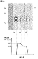
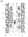
- FIG. 3 is a plan view illustrating a scene of a lane change on a three-lane road according to the embodiment of the present invention, and a graph illustrating lateral speed control according to the first embodiment of the vehicle travel control device according to the present invention.
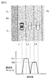
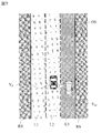
- FIG. 3 is a plan view illustrating a scene of a lane change on a four-lane road according to the embodiment of the present invention, and a graph illustrating lateral speed control according to the first embodiment of the vehicle travel control device according to the present invention. .
- FIG. 3 is a plan view illustrating a scene of a lane change on a four-lane road according to the embodiment of the present invention, and a graph illustrating lateral speed control according to the first embodiment of the vehicle travel control device according to the present invention. .
- FIG. 4 is a plan view showing a scene of a lane change according to the embodiment of the present invention, and a lateral speed for temporarily setting the lateral speed to zero before the second lane change in the first embodiment of the vehicle travel control device according to the present invention. It is a figure showing a graph explaining control. It is a figure which shows the top view which shows the scene of the lane change which concerns on embodiment of this invention, and the graph explaining the lateral speed control which concerns on 2nd Embodiment of the drive control apparatus of the vehicle which concerns on this invention (the 1). .
- the 2 which shows a top view showing a scene of a lane change concerning an embodiment of the present invention, and a graph explaining lateral speed control concerning a 2nd embodiment of a run control device of vehicles concerning the present invention.
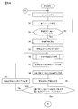
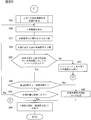
- It is a flowchart (the 1) which shows the lane change control processing of the traveling control device of the vehicle concerning the embodiment of the present invention.
- It is a flowchart (the 2) which shows the lane change control processing of the driving
- FIG. 1 is a block diagram showing the configuration of the vehicle travel control device 1 according to the present embodiment.
- the travel control device 1 for a vehicle according to the present embodiment is also an embodiment that implements the travel control method for a vehicle according to the present invention.
- the vehicle travel control device 1 according to the present embodiment includes a sensor 11, a vehicle position detection device 12, a map database 13, an in-vehicle device 14, a presentation device 15, an input device 16 , A communication device 17, a drive control device 18, and a control device 19.
- These apparatuses are connected to each other by, for example, a CAN (Controller Area Network) or another in-vehicle LAN in order to mutually transmit and receive information.
- CAN Controller Area Network
- the sensor 11 detects a traveling state of the own vehicle.
- a front camera that images the front of the host vehicle
- a rear camera that images the rear of the host vehicle
- a front radar that detects an obstacle in front of the host vehicle
- a rear that detects an obstacle behind the host vehicle.
- Examples include a radar, a side radar for detecting obstacles present on the left and right sides of the host vehicle, a vehicle speed sensor for detecting the vehicle speed of the host vehicle, and an in-vehicle camera for imaging the driver.
- the sensor 11 may be configured to use one of the plurality of sensors described above, or may be configured to use a combination of two or more types of sensors.
- the detection result of the sensor 11 is output to the control device 19 at predetermined time intervals.
- the own-vehicle position detecting device 12 includes a GPS unit, a gyro sensor, a vehicle speed sensor, and the like, detects radio waves transmitted from a plurality of satellite communications by the GPS unit, and periodically transmits position information of a target vehicle (own vehicle).
- the current position of the target vehicle is detected based on the obtained position information of the target vehicle, the angle change information obtained from the gyro sensor, and the vehicle speed obtained from the vehicle speed sensor.
- the position information of the target vehicle detected by the vehicle position detection device 12 is output to the control device 19 at predetermined time intervals.
- the map database 13 stores map information including positional information of various facilities and specific points. Specifically, positional information such as a merging point, a branch point, a tollgate, a decreasing position of the number of lanes, and a service area (SA) / parking area (PA) is stored together with map information. Further, the map information includes information on roads such as road type, road width, number of lanes, road radius, presence / absence of right / left-turn dedicated lanes, the number of dedicated lanes, and speed limit.
- the map information stored in the map database can be referred to by the control device 19.
- the on-vehicle device 14 is various devices mounted on the vehicle, and operates by being operated by a driver. Examples of such in-vehicle devices include steering, accelerator pedals, brake pedals, navigation devices, audio devices, air conditioners, hands-free switches, power windows, wipers, lights, direction indicators, horns, and specific switches. When the in-vehicle device 14 is operated by the driver, the information is output to the control device 19.
- the presentation device 15 includes, for example, a display included in a navigation device, a display incorporated in a room mirror, a display incorporated in a meter unit, a head-up display projected on a windshield, a speaker included in an audio device, and a vibrating body embedded therein. Such as a seat device.
- the presentation device 15 notifies the driver of presentation information and lane change information, which will be described later, under the control of the control device 19.
- the input device 16 is, for example, a device such as a dial switch that can be manually input by a driver, a touch panel arranged on a display screen, or a microphone that can be input by a driver's voice.
- the driver operates the input device 16 to input response information to the presentation information presented by the presentation device 15.
- a direction indicator or a switch of another vehicle-mounted device 14 can be used as the input device 16. By turning on the switch of the indicator, it is also possible to input a consent or permission to change lanes. Note that the response information input by the input device 16 is output to the control device 19.
- the communication device 17 communicates with a communication device outside the vehicle.
- the communication device 17 performs inter-vehicle communication with another vehicle, performs inter-vehicle communication with a device installed on the shoulder of a road, or communicates with an information server installed outside the vehicle.
- Various information can be obtained from an external device by performing wireless communication or the like.
- the information acquired by the communication device 17 is output to the control device 19.
- the drive control device 18 controls the traveling of the own vehicle.
- the drive control device 18 includes a drive mechanism for realizing the acceleration / deceleration and the vehicle speed so that the distance between the host vehicle and the preceding vehicle is constant when the own vehicle controls the following of the preceding vehicle. (Including the operation of the internal combustion engine for an engine vehicle, the operation of the traction motor for an electric vehicle, and the torque distribution between the internal combustion engine and the traction motor for a hybrid vehicle) and brakes Control behavior. Also, lane keeping control for detecting a lane mark of a lane in which the vehicle travels (hereinafter, also referred to as the vehicle lane) and controlling a traveling position of the vehicle in the width direction so that the vehicle travels in the vehicle lane.
- the vehicle lane lane keeping control for detecting a lane mark of a lane in which the vehicle travels (hereinafter, also referred to as the vehicle lane) and controlling a traveling position of the vehicle in the width direction so that the vehicle travels in the vehicle lane.
- the vehicle When the vehicle performs lane change control such as passing of the preceding vehicle or changing the traveling direction, or when performing traveling control of turning right or left at an intersection, etc., it is necessary to realize acceleration / deceleration and vehicle speed.
- the drive control device 18 controls the traveling of the host vehicle in accordance with an instruction from a control device 19 described later. Further, as the traveling control method by the drive control device 18, other known methods can be used.
- the control device 19 includes a ROM (Read Only Memory) storing a program for controlling traveling of the own vehicle, a CPU (Central Processing Unit) executing the program stored in the ROM, and an accessible storage device. It consists of a functioning RAM (Random Access Memory).
- ROM Read Only Memory
- CPU Central Processing Unit
- RAM Random Access Memory
- an operation circuit instead of or together with a CPU (Central Processing Unit), an MPU (Micro Processing Unit), a DSP (Digital Signal Processor), an ASIC (Application Specific Integrated Circuit Circuit), an FPGA (Field Programmable Gate Array), etc. Can be used.
- the control device 19 executes a program stored in the ROM by the CPU to obtain a traveling information acquisition function for acquiring information on the traveling state of the own vehicle, a traveling scene determination function for determining a traveling scene of the own vehicle, The driver provides a travel control function that controls the travel of the vehicle, a lane change control function that automatically determines whether or not lane changes are possible, and controls lane changes, and lane change information related to the running behavior of the own vehicle by lane change control. And a consent confirmation function for confirming whether or not the driver has accepted the lane change with respect to the presented lane change information.
- a traveling information acquisition function for acquiring information on the traveling state of the own vehicle
- a traveling scene determination function for determining a traveling scene of the own vehicle
- the driver provides a travel control function that controls the travel of the vehicle, a lane change control function that automatically determines whether or not lane changes are possible, and controls lane changes, and lane change information related to the running behavior of the own vehicle by lane change control.
- the driving information obtaining function of the control device 19 is a function of obtaining driving information relating to the driving state of the host vehicle.
- the control device 19 uses the running information acquisition function to run the image information of the outside of the vehicle captured by the front camera and the rear camera included in the sensor 11 and the detection results by the front radar, the rear radar, and the side radar. Get as information.
- the control device 19 also acquires, as travel information, vehicle speed information of the own vehicle detected by a vehicle speed sensor included in the sensor 11 and image information of a driver's face imaged by an in-vehicle camera, by a travel information acquisition function.
- the control device 19 obtains information on the current position of the own vehicle as running information from the own vehicle position detecting device 12 by the running information obtaining function.
- the control device 19 uses the traveling information acquisition function to output position information such as a junction, a branch point, a tollgate, a position where the number of lanes is reduced, a service area (SA) / a parking area (PA) from the map database 13 as traveling information. get.
- the control device 19 uses the traveling information acquisition function to provide information such as road type, road width, number of lanes, road radius, presence / absence of a right / left turn dedicated lane, the number of dedicated lanes, and speed limit as map information as travel information. Obtained from the database 13.
- the control device 19 obtains operation information of the in-vehicle device 14 by the driver, for example, the intermittent speed of the wiper or the like, from the in-vehicle device 14 as running information by the running information obtaining function.
- the driving scene determination function of the control device 19 refers to a table stored in the ROM of the control device 19 and determines a driving scene in which the host vehicle is traveling.
- FIG. 2 is a diagram illustrating an example of the table. As shown in FIG. 2, the table stores a traveling scene suitable for changing lanes and a determination condition thereof for each traveling scene.
- the control device 19 refers to the table shown in FIG. 2 and determines whether or not the traveling scene of the own vehicle is a traveling scene suitable for changing lanes by using the traveling scene determination function.
- the control device 19 uses the traveling scene determination function to detect, for example, a result of detection by a front camera or a forward radar included in the sensor 11, a vehicle speed of the own vehicle detected by a vehicle speed sensor, and a position of the own vehicle by the own vehicle position detection device 12. It is determined whether or not the own vehicle satisfies the above condition based on the information and the like.
- control device 19 determines whether or not the determination conditions are satisfied for all the driving scenes registered in the scene determination table illustrated in FIG. 2 by the driving scene determination function.
- the lane change prohibition conditions include, for example, “running in a lane change prohibition area”, “an obstacle exists in the lane change direction”, “every time a center line (road center line) is straddled”, And “becoming on the shoulder or straddling the road edge”.
- the condition of “entering the road shoulder or straddling the road edge” is permitted in the “emergency evacuation scene”. You can also. In the table shown in FIG. 2, the necessity of lane change, the time limit, and the direction of lane change will be described later.
- the control device 19 determines the traveling scene having the higher necessity of the lane change as the traveling scene of the own vehicle when the traveling scene of the own vehicle corresponds to a plurality of traveling scenes. I do.
- the traveling scene of the own vehicle corresponds to the “scene of catching up with the preceding vehicle” and the “scene of changing lanes to the destination”, and the necessity of the lane change in the “scene of catching up with the preceding vehicle”
- X1 is lower than the necessity X8 of lane change in the “lane transfer scene to destination” (X1 ⁇ X8).
- the control device 19 determines the “lane transfer scene to the destination” having the higher necessity of the lane change as the traveling scene of the own vehicle by the traveling scene determination function.
- the “lane transfer scene to the destination” is a lane in the target branch direction or exit direction from the lane where the vehicle is currently traveling, such as at a branch point of a road having a plurality of lanes or just before an exit. This refers to a scene in which the lane is changed to transfer to.
- the traveling control function of the control device 19 is a function of controlling traveling of the own vehicle.
- the control device 19 detects the lane mark of the own lane on which the own vehicle travels based on the detection result of the sensor 11 by the travel control function, and controls the own vehicle so that the own vehicle travels in the own lane. Lane keeping control for controlling the traveling position in the width direction is performed.
- the control device 19 causes the drive control device 18 to control the operation of the steering actuator and the like so that the vehicle travels at an appropriate traveling position by the traveling control function.
- the control device 19 can also perform a follow-up traveling control that automatically follows the preceding vehicle at a predetermined inter-vehicle distance from the preceding vehicle by the traveling control function.
- the control device 19 When performing the following travel control, the control device 19 outputs a control signal to the drive control device 18 by a travel control function so that the own vehicle and the preceding vehicle travel at a constant inter-vehicle distance, and outputs an engine, a brake, and the like. Control the operation of the drive mechanism of In the following, description will be made as automatic travel control, including lane keeping control, following travel control, right / left turn travel control, and lane change control.
- the vehicle lane change control function of the control device 19 is a function of determining whether or not to perform a lane change based on the traveling scene of the own vehicle and information on obstacles existing around the own vehicle.
- the lane change control function is also a function of causing the drive control device 18 to control the operation of a drive mechanism such as an engine or a brake and the operation of a steering actuator when it is determined that a lane change is to be performed.
- the lane change control function is a function of setting a start timing for starting the lane change control based on the traveling state of the own vehicle and the state of the driver, and executing the lane change control in accordance with the set start timing. .
- the lane change control function includes a function of changing lanes two or more lanes in the same direction continuously from the own lane, and a function of controlling the lateral speed of the vehicle when changing lanes continuously two or more lanes. included.
- the surrounding situation is checked with the sensor 11 or the like before the start of each lane change, but the time elapses until the second or later lane change is started. May change the surrounding situation.
- the lateral speed of the second or later lane change control is changed so that the lane can be changed two or more lanes in the same direction continuously in the same direction.
- the lateral speed is controlled so as to be lower than the lateral speed of the lane change control.
- the lateral speed of the vehicle is a moving speed with respect to an axis perpendicular to an axis based on the traveling direction of the vehicle. That is, when the vehicle is traveling in the traveling lane, the traveling speed of the traveling lane in the width direction is the lateral speed of the vehicle.
- 3A is a diagram showing lateral speed control during continuous lane change according to an embodiment of the present invention, and a plan view showing a running scene of lane change of the vehicle V 0, the vehicle V 0 which lane change 2 shows a graph for explaining the lateral position and the lateral speed of the vehicle.
- Plan view of Figure 3A in the road three lanes L1, L2, L3 of the left-hand traffic, due to the presence of branch point of the road ahead, through the adjacent lane L2 the vehicle V 0 from the lane L1 traveling It is a top view which shows the example of the lane change control which performs continuous lane change to the adjacent lane L3.
- the traveling lane L3 of the vehicle V 0 is the rightmost, if there is an outlet of a motorway in the front left, changes the traveling direction to the exit, the current lane It is necessary to continuously change the lane from L3 to the leftmost lane L1 via the lane L2, but the same control is performed in such a case.
- Controller 19 the automobile line change control function, as shown in the graph of FIG 3A, in the own inside lane L1, a first lateral speed set lateral velocity Vh of the host vehicle V 0 to (m / s) in advance It accelerates to Vh1, and changes lanes from the own lane L1 to the adjacent lane L2 while maintaining the first lateral speed Vh1. Then, the control device 19, the car line change control function, and decelerated to a second lateral speed Vh2 set in advance the lateral velocity Vh of the host vehicle V 0 in the adjacent lane L2, the second lateral speed Vh2 The lane is changed from the adjacent lane L2 to the adjacent lane L3 while maintaining the state.
- the relationship between the first lateral speed Vh1 and the second lateral speed Vh2 is Vh1> Vh2.
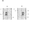
- the horizontal speed at which the vehicle V 0 changes the lane, the lane mark vehicle V 0 was arranged between lanes is a lateral speed when crossing the CL.
- the vehicle V 0 crosses the target lane mark CL for example, as shown in FIGS. 4 (A), (B) , when performing the lane change from the left lane L1 to the right of the lane L2, from stepping on the right front wheel target lane mark CL of the vehicle V 0, the left rear wheel refers to over target lane mark CL.
- the control is performed at a lower speed than the first vehicle lane change control. Therefore, before starting the second or subsequent lane change control, the time for checking the surrounding situation with the sensor 11 or the like becomes longer, so that the surrounding situation can be appropriately confirmed.
- the safety of the lane change control is further enhanced.
- control device 19 also performs the same lateral speed control when the vehicle lane change control function performs two or more consecutive lane change controls on a road having three or more lanes on each side. For example, when three consecutive lane change control operations are performed on a four-lane road on the left side, the lateral speed of the first lane change control is set to the first lateral speed Vh1, and the second lateral speed is set to the second lateral speed. And the lateral speed of the third vehicle line change control is set to the second lateral speed Vh2 lower than the first lateral speed Vh1.
- the lateral speed of the (n + 2) th lane change control may be set to be lower than the lateral speed of the (n + 1) th lane change control.
- the lateral speed of the first vehicle lane change control from the lane L1 to the lane L2 is defined as a first lateral speed Vh1.
- the lateral speed of the second lane change control from the lane L2 to the lane L3 is set to the second lateral speed Vh2 lower than the first lateral speed Vh1, and the third lane change from the lane L3 to the lane L4 is performed.
- the control lateral speed is set to a third lateral speed Vh3 lower than the second lateral speed Vh2.
- the lateral velocity control shown in FIG. 3A although the lateral speed Vh of the host vehicle V 0 in the lane L2 is decelerating from the first lateral velocity Vh1 to a second lateral speed Vh2, as shown in FIG. 3C Alternatively, the lane keeping control may be performed by temporarily setting the first lateral speed Vh1 to zero in the lane L2, and the vehicle may be accelerated to the second lateral speed Vh2 in the lane L2 to perform the second vehicle lane change control.
- the lateral speed appropriately check the surroundings in the second or subsequent lane change, to the following vehicle can be clearly recognized lane change of the vehicle V 0.
- a preset second lateral speed Vh2, a third lateral speed Vh3, or the like is used as the lateral speed of the second or later vehicle lane change control.
- the lateral speed of the second or subsequent lane change control may be set according to the travel information.
- the second to fifth embodiments for setting the lateral speed for the second and subsequent times based on the travel information acquired by the travel information acquisition function of the control device 19 will be described.
- 3D and 3E show lateral speed control according to the second embodiment of the present invention.
- the control device 19 sets the lateral speed of the second or subsequent lane change control according to the direction of the lane change by the lane change control function. That is, the slow average speed lane, if the average travel speed makes a lane change to the fast lane, the relative speed of the following vehicle relative to the own vehicle V 0 becomes faster, the following vehicle and the subject vehicle V 0 since the vehicle-to-vehicle distance is close, time to check the surrounding conditions for the vehicle V 0 the second and subsequent lane change is shortened.
- the second and subsequent lane change control is performed at a lower speed.
- Controller 19 the automobile line change control function, based on the travel information, whether the average traveling speed of the own lane on which the vehicle V 0 is traveling, or faster than the average speed of the traffic lane of the lane change destination Is determined.
- Average traveling speed of the host vehicle lane may be applied to the vehicle traveling speed V 0 or image information and the outside of the vehicle captured by the rear camera of the vehicle V 0,, the detection result by the rear radar Alternatively, the detection may be performed based on the above. Further, the average traveling speed of the lane of the lane change destination of the vehicle and an external image information captured by the vehicle V 0 which the rear camera may be detected based on the detection result by the rear radar.
- the travel information information on the lane position of the own lane and information on the lane position of the lane to which the lane is changed are acquired from the map information, and the average travel of the own lane is performed based on the acquired information on the lane position. It may be determined whether or not the speed is faster than the average traveling speed of the lane to which the lane is to be changed. For example, on a road with two or more lanes on one side, the average traveling speed may differ depending on the lane position. On roads in Japan, the rightmost passing lane is more average than the leftmost lane. Speed is fast.
- the lane position it can be determined whether or not the average traveling speed of the own lane is faster than the average traveling speed of the lane to which the lane is changed.
- the lane positions of the traveling lane and the overtaking lane vary depending on the country or region, the difference between right-hand traffic or left-hand traffic, traffic rules, and the like. Therefore, it is desirable to determine the lane position according to the road on which the vehicle travels.
- the controller 19 uses the lane change control function to average the traveling of the lane to which the lane is changed.
- the lateral speed set in the second or later lane change control is set to be lower than when the speed is lower than the average traveling speed of the own lane. That is, the control device 19 performs the second or later lane change control at a lower speed when the lane change is performed from the lane having the slower average traveling speed to the faster lane by the lane change control function.
- the driving scene shown in the plan view of FIG. 3D shows a case where two consecutive lane change controls are performed from the right-hand lane L3 to the left-hand lane L1.
- the average travel speed of the lane L1, L2, L3 determined from the travel information, respectively 80km / h, 90km / h, when it is 100km / h, the average of the own lane L3 of the vehicle V 0 is traveling
- the appropriate traveling speed is determined to be faster than the average traveling speed of the lane L1 at the lane change destination. Note that this determination result is the same even when the determination is made based on the lane positions of the lanes L1 and L3.
- Such a running scene is a lane change from a lane with a high average running speed to a lane with a low average running speed. Therefore, the relative speed of the following vehicle relative to the own vehicle V 0 by a lane change is not fast, the control device 19, the car line change control function, as shown in the graph of FIG. 3D, the automobile line change control for the first time
- a preset first lateral speed Vh1 is set and executed
- a preset second lateral speed Vh2 is set and executed for the second vehicle lane change control.
- the traveling scene shown in the plan view of FIG. 3E shows a case in which two consecutive lane change control operations are performed from the leftmost traveling lane L1 to the rightmost passing lane L3.
- the average travel speed of the lane L1, L2, L3 determined from the travel information, as with FIG. 3D, respectively 80km / h, 90km / h, when it is 100km / h, the vehicle V 0 is traveling It is determined that the average traveling speed of the own lane L1 is lower than the average traveling speed of the lane L3 at the lane change destination. Note that this determination result is the same even when the determination is made based on the lane positions of the lanes L1 and L3.
- Such a traveling scene is a lane change from a lane with a slow average traveling speed to a lane with a fast average traveling speed. Therefore, the control device 19 sets and executes the first lateral speed Vh1 set in advance for the first vehicle lane change control, as shown in the graph of FIG.
- the fourth lateral speed Vh4 which is slower than the second lateral speed Vh2, is set and executed in the vehicle lane change control.
- the relationship among the first lateral speed Vh1, the second lateral speed Vh2, and the fourth lateral speed Vh4 is Vh1>Vh2> Vh4.
- the fourth lateral speed Vh4 is calculated by the vehicle lane change control function of the control device 19 using the following equation (a).
- C1 in the following equation (a) is a coefficient used for calculating the fourth lateral speed Vh4, and a numerical value of 1 or less is used. Further, the coefficient C1 may be reduced as the speed difference between the own lane and the lane to which the lane is changed is larger.
- Vh4 Vh2 ⁇ C1 (a)
- the second and subsequent lane changes when the vehicle moves from a lane with a low average traveling speed to a lane with a high average traveling speed, the lateral speed of the lane change control for the second and subsequent times is made slower. Therefore, the second or later lane change control is performed at a lower speed, and the time required to check the surrounding situation with the sensor 11 or the like before starting the second or later lane change control becomes longer. Therefore, the surrounding situation can be appropriately confirmed. Further, the following vehicle since the time to check the lane change of the vehicle V 0 becomes long, the lane change is likely to recognize. Therefore, the safety of the lane change control is further enhanced.
- the coefficient C1 smaller as the speed difference between the own lane and the lane to which the lane is changed is larger, the smaller the speed difference, the lower the speed of the second or later lane change control, so that the surrounding situation can be reduced. reaffirmed properly, it is possible to clearly recognize the lane change of the vehicle V 0 to the following vehicle.
- FIG. 3F shows lateral speed control according to the third embodiment of the present invention.
- the control device 19 sets the lateral speed of the second or subsequent lane change control according to the traffic congestion degree K by the lane change control function. That is, when the traffic congestion degree K around the own vehicle V 0 is high, the distance between the own vehicle V 0 and other surrounding vehicles is short, so that the own vehicle V 0 is used for the second and subsequent lane changes. The time to check the surrounding situation is shortened. In order to solve this, in the present embodiment, when the traffic congestion degree K is high, the lateral speed is set so that the second or later lane change control is performed at a lower speed.
- the control device 19 obtains the degree of traffic congestion K based on the travel information by the lane change control function.
- Traffic congestion K for example, inter-vehicle distance to the preceding vehicle V 2, distance to the following vehicle V 3, the number of nearby vehicles, VICS congestion included in the (R) information, legal speed and the vehicle V 0 Is determined based on the degree of deviation from the actual vehicle speed.
- Traffic congestion K is preceded as inter-vehicle distance between the vehicle V 2 is short, the shorter the distance to the following vehicle V 3, as the number of nearby vehicles is large, the higher the degree of congestion included in the VICS information, or The higher the deviation between the legal speed and the actual vehicle speed of the own vehicle, the higher the judgment.
- the control device 19 uses the vehicle line change control function to set the first vehicle line change control to the first vehicle line change control as shown in the graph of FIG. 3F. Is set and executed, and the second lateral speed Vh2 is set and executed for the second vehicle lane change control.
- the control device 19 sets the first lateral speed Vh1 preset in the first vehicle line change control by the vehicle line change control function.
- the second vehicle speed change control is executed with the fifth lateral speed Vh5 lower than the second lateral speed Vh2 set.
- the relationship among the first lateral speed Vh1, the second lateral speed Vh2, and the fifth lateral speed Vh5 is Vh1>Vh2> Vh5.
- the fifth lateral speed Vh5 is calculated by the vehicle lane change control function of the control device 19 using the following equation (b).
- C2 in the following equation (b) is a coefficient used for calculating the fifth lateral speed Vh5, and a numerical value of 1 or less is used. Further, the coefficient C2 may be reduced as the traffic congestion degree K increases.
- Vh5 Vh2 ⁇ C2 (b)
- the lateral speed of the second or later lane change control is made slower.
- the change control is performed at a lower speed, and the time for checking the surrounding conditions before starting the second or later lane change becomes longer. Therefore, the surrounding situation can be appropriately confirmed. Further, the following vehicle since the time to check the lane change of the vehicle V 0 becomes long, the lane change is likely to recognize. Therefore, the safety of the lane change control is further enhanced.
- the coefficient C2 smaller as the traffic congestion degree K is higher, the second or later lane change control is performed at a lower speed as the traffic congestion degree K is higher. the lane change of the vehicle V 0 can be clearly recognized by the following vehicle.
- FIG. 3G shows lateral speed control according to the fourth embodiment of the present invention.
- the control device 19, the car line change control function sets the lateral speed of the vehicle line change control for the second time since according to the radial Lr runway on which the vehicle V 0 is traveling. That is, when the radius Lr of the runway is small, the outlook is poor, the vehicle V 0 is less likely to check a sensor 11 the ambient conditions for a second lane change.
- the lateral speed is set so that the second or later lane change control is performed at a lower speed.
- the control device 19 obtains the radius Lr of the road from the map information which is the driving information by the vehicle line changing control function.
- the lane for which the radius Lr is obtained may be the own lane or the lane to which the lane is changed.
- the control device 19 uses the lane change control function to set the first lane change control set in advance to the first lane change control as shown in the graph of FIG. 3G. Is set and executed, and the second lateral speed Vh2 is set and executed for the second vehicle lane change control.
- the control device 19 sets the first lateral speed Vh1 preset in the first vehicle line change control by the vehicle line change control function.
- the second lateral speed Vh6, which is slower than the second lateral speed Vh2, is set and executed in the second vehicle line change control.
- the sixth lateral speed Vh6 is calculated by the vehicle lane change control function of the control device 19 using the following equation (c).
- C3 in the following equation (c) is a coefficient used for calculating the sixth lateral speed Vh6, and a numerical value of 1 or less is used. Further, the coefficient C3 may be reduced as the radius Lr of the runway decreases.
- Vh6 Vh2 ⁇ C3 (c)
- the lateral speed of the second or later lane change control is made slower.
- the control is performed at a lower speed, and the time for checking the surroundings before starting the second lane change becomes longer. Therefore, the surrounding situation can be appropriately confirmed.
- the following vehicle since the time to check the lane change of the vehicle V 0 becomes long, the lane change is likely to recognize. Therefore, the safety of the lane change control is further enhanced.
- the second or subsequent lane change control is performed at a lower speed as the radius Lr of the runway is smaller. the lane change of the vehicle V 0 can be clearly recognized by the following vehicle.
- FIG. 3H is a graph illustrating lateral speed control according to the fifth embodiment of the present invention.
- the control device 19 sets the lateral speed of the second or later lane change control according to the rainfall Rf by the lane change control function. That is, when rainfall Rf is large, becomes surroundings is hardly confirmed because the second lane change by a sensor 11 of the vehicle V 0.
- the lateral speed is set so that the second or later lane change control is performed at a lower speed.
- the control device 19 obtains the rainfall Rf from the intermittent speed of the wiper, which is the traveling information, by the vehicle lane change control function.
- the vehicle V 0 is provided with a raindrop sensor
- from the detection result of the raindrop sensor may obtain the travel information "rainfall”, combining the intermittent rate of the detection result and the wiper of the raindrop sensor May be used to determine “rainfall”.
- the control device 19 uses the vehicle lane change control function, as shown in the graph of FIG.
- the speed Vh1 is set and executed, and the second lateral speed Vh2 is set and executed for the second vehicle lane change control.
- the control device 19 sets and executes the first lateral speed Vh1 preset in the first vehicle line change control by the vehicle line change control function. Then, a seventh lateral speed Vh7 slower than the second lateral speed Vh2 is set and executed for the second vehicle line change control.
- the relationship among the first lateral speed Vh1, the second lateral speed Vh2, and the seventh lateral speed Vh7 is Vh1>Vh2> Vh7.
- the seventh lateral speed Vh7 is calculated by the vehicle lane change control function of the control device 19 using the following equation (d).
- C4 in the following equation (d) is a coefficient used for calculating the seventh lateral velocity Vh7, and a numerical value of 1 or less is used. Further, the coefficient C4 may be reduced as the rainfall Rf increases.
- Vh7 Vh2 ⁇ C4 (d)
- the lateral speed of the second or later lane change control is made slower. It takes place at a lower speed, which increases the time to check the surroundings before starting the second lane change. Therefore, the surrounding situation can be appropriately confirmed. Further, the following vehicle since the time to check the lane change of the vehicle V 0 becomes long, the lane change is likely to recognize. Therefore, the safety of the lane change control is further enhanced. Further, by setting the coefficient C4 to be smaller as the rainfall Rf is larger, the second or subsequent lane change control is performed at a lower speed as the rainfall Rf is larger. it is possible to clearly recognize the lane change of the vehicle V 0.
- the second to fifth embodiments may be used alone or in an appropriate combination.
- the second lateral speed Vh2 is multiplied by the C1 to C4 coefficients and the second or later vehicle lane change control is performed. Lateral speed can be obtained.
- the running condition of the vehicle V 0 is, if satisfying the conditions of a plurality of travel information of the second to fifth embodiments, the automobile line change control for the second and subsequent times obtained from the second lateral velocity Vh2 Lateral speed becomes extremely slow and it takes too much time to change lanes.
- a lower limit is set in advance for the lateral speed of the second or later lane change control, and if the calculated lateral speed is lower than the lower limit, the lower limit is set to the lateral speed of the second or later lane change control. You may make it set as.
- the lateral speed control according to the first embodiment when performing two or more continuous lane change controls on a road having three or more lanes on one side, the lateral speed control according to the first embodiment may be omitted.
- the lateral speed of the (n + 1) th lane change control may be equal to the lateral speed of the (n + 2) th lane change control, or the lateral speed of the (n + 2) th lane change control may be set to (n + 1). ) It may be set to be slower than the lateral speed of the second lane change control.
- the lateral speed of the (n + 2) th lane change control is set to be lower than the lateral speed of the (n + 1) th lane change control
- a coefficient is multiplied by the lateral speed of the immediately preceding lane change control.
- the fourth lateral speed obtained for the second lane change control is multiplied by a coefficient C1 to perform the third lane change control.
- the first lateral speed Vh1 is temporarily reduced to zero within the lane L2 as in the lateral speed control according to the first embodiment. Then, the lane keeping control may be performed to accelerate the vehicle to the second lateral speed Vh2 in the lane L2 to perform the second vehicle lane change control.
- the lane change information presentation function is a function of presenting to the driver via the presenting device 15 lane change information relating to the running operation of the own vehicle under the lane change control. For example, if there is a branch point of a road ahead or an exit of an exclusive motorway during the execution of the lane keep control, the traveling direction of the own vehicle may be changed and the lane may need to be changed. . Also, if the preceding vehicle changes lanes during execution of the follow-up running control of the preceding vehicle, the own vehicle may change lanes accordingly.
- the control device 19 determines whether or not the lane change is possible, and if the lane change is possible, prompts the driver to confirm safety.
- the lane change information is presented to the driver by the presentation function. Since the timing of presenting the lane change information is for the purpose of confirming safety by the driver itself, it may be at least before the start of the lane change control, but during the execution of the lane change control and / or the completion of the lane change control At any time, the lane change information may be presented.
- the form of presentation to the presentation device 15 by the lane change information presentation function is such that, when the presentation device 15 includes a display, in addition to displaying a visual pattern including an image and a language, the presentation device 15 includes a speaker.
- Uses the lane change information for example, guidance information for changing the lane to the left or right lane
- auditory information voice or sound
- the presentation device 15 includes one or more warning lamps installed on an instrument panel or the like, a specific warning lamp is turned on in a specific presentation mode, so that the vehicle moves by the lane change control.
- the lane change information including the width direction to be performed may be presented to the driver.
- the presentation device 15 includes a seat device in which a plurality of vibrating bodies are embedded, by vibrating a specific vibrating body in a specific presentation mode, the width direction in which the own vehicle moves by the lane line change control. Lane change information including the direction may be presented to the driver.
- the driver can more intuitively grasp the lane change information.
- the consent confirmation function of the control device 19 is a function for confirming whether or not the driver has accepted the lane change control with respect to the lane change information presented by the lane change information presentation function.
- the control device 19 performs an input operation on the input device 16 by the driver, for example, an operation of a dial switch or a display on the display screen.
- the operation of the touch panel, the voice input to the microphone, the operation of the direction indicator, and the like are received.
- the control device 19 determines, based on these input operations, whether or not the driver has accepted the lane change control by the acceptance confirmation function.
- 5A to 5E are flowcharts illustrating the lane change control processing according to the present embodiment.
- the lane change control process described below is executed by the control device 19 at predetermined time intervals.
- the lane keeping control for controlling the traveling position in the width direction of the own vehicle is performed by the traveling control function of the control device 19 so that the own vehicle travels in the own lane.
- the description will be given on the assumption that it is necessary to change the lane to the adjacent lane (the lane further beyond the adjacent lane) for the input destination.
- the lateral speed control performed when changing lanes will be described for the case where the lateral speed of the second or later lane change control is set according to the traffic congestion degree of the third embodiment.
- step S1 of FIG. 5A the control device 19 acquires the traveling information on the traveling state of the own vehicle by the traveling information acquiring function.
- step S2 the control device 19 determines the traveling scene of the own vehicle by the traveling scene determination function based on the traveling information acquired in step S1.
- step S3 the control device 19 uses the traveling scene determination function to determine whether the traveling scene of the own vehicle determined in step S2 is a traveling scene suitable for changing lanes. Specifically, the traveling scene determination function determines that the traveling scene of the own vehicle is a traveling scene suitable for changing lanes when the traveling scene of the own vehicle is any of the traveling scenes shown in FIG. I do. If the traveling scene of the own vehicle is not a traveling scene suitable for changing lanes, the process returns to step S1, and the determination of the traveling scene is repeated. On the other hand, if the traveling scene of the host vehicle is a traveling scene suitable for changing lanes, the process proceeds to step S4.
- step S4 the control device 19 detects the target range by the vehicle lane change control function. Specifically, the control device 19 uses the vehicle lane change control function to detect image information outside the vehicle captured by the front camera and the rear camera included in the sensor 11 and to detect the image information by the front radar, the rear radar, and the side radar. Based on the traveling information including the result, an obstacle existing around the own vehicle is detected. Then, the control device 19 detects, as the target range, a range that is located on the side of the own vehicle and has no obstacles, by the lane change control function.
- the “target range” in the present embodiment is a relative range based on a running position when the own vehicle runs at the current speed, and other vehicles existing around the own vehicle are different from the own vehicle. When traveling straight at the same speed, the target range will not change.
- the side of the own vehicle refers to the target position of the lane change when the own vehicle changes lanes (this target position is also a relative position based on the running position when the own vehicle runs at the current speed). Position), and the range (direction, width, angle, etc.) can be set as appropriate.
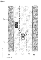
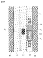
- FIGS. 6A to 6F are plan views for explaining the target range.
- Example shown in FIG. 6A is a vehicle V 0 is traveling lane further beyond next adjacent lane L2 and the adjacent lane L2 adjacent to the lane L1 L3 (hereinafter, also referred to as next adjacent lane L3.) Obstacle other it is a scene in which the vehicle V 1 does not exist.
- the control device 19 detects the adjacent lane L2 and the adjacent lane L3 as the target range OS by the lane change control function.
- the road shoulder RS is a range in which the lane cannot be changed in principle, and is excluded from the target range OS.
- a running scene of the vehicle V 0 is "emergency evacuation scene" in the road such as a stop to shoulder RS in an emergency is allowed, it is possible to include shoulder RS in scope OS (hereinafter, the same .).
- Example shown in FIG. 6B but the other vehicle V 1 becomes an obstacle in the adjacent lane L2 which is adjacent to the lane L1 on which the vehicle V 0 is traveling, V 1 is present, the adjacent lane L2, the vehicle V 0 between the other vehicle V 1 and the other vehicle V 1 of the rear of the front than but adjacent lane L1 to travel, there is a range of other vehicles V 1, V 1 is absent, further obstacle next adjacent lane L3 it is a scene in which the other vehicle V 1 does not exist is.
- the control device 19 detects, as the target range OS, a range in which there is no other vehicle in the adjacent lane L2 and the adjacent lane L3 by the vehicle lane change control function.
- Example shown in Figure 6C there is a range that no other vehicle V 1, V 1 Examples as well as the adjacent lane L2 shown in FIG. 6B, also in the next adjacent lane L3, front and rear of the other vehicle V 1, V This is a scene in which there is a range in which no other vehicle exists between 1 .
- the control device 19 the car line change control function, a range of other vehicles V 1, V 1 is absent in the adjacent lane L2, and a range of other vehicles V 1, V 1 is absent in the next adjacent lane L3 , As the target range OS.
- the range RA of the vehicle V 0 can not travel, in addition to the construction period, and the range of the other vehicle V 1 is parked or stopped, such as by traffic control traveling of the vehicle, and the like extent prohibited.
- the range RA of the vehicle V 0 can not be run due to construction section, for example in the case of more than half of the next adjacent lane L3 (more than half in the width direction) is less than the other half of The range may be excluded from the target range OS.
- the control device 19 determines that the target range OS cannot be detected by the vehicle line change control function.
- 6F is an example in which the lane change from the adjacent lane L2 to the adjacent lane L3 is prohibited by the lane change prohibition mark RL.
- the control device 19 determines that the target range OS cannot be detected by the vehicle line change control function.
- the control device 19 of this embodiment the automobile line change control function, of the left and right direction, the direction to be the lane change in the running scene of the vehicle V 0, the direction of the target range OS suitable for lane change To detect.
- directions suitable for changing lanes in each traveling scene are stored in the table shown in FIG. 2 in advance.
- the control device 19 obtains information on “direction of lane change” in the traveling scene of the own vehicle with reference to the table shown in FIG. 2 by the lane change control function. For example, when the traveling scene of the own vehicle is a "lane transfer scene to the destination", the lane change control function refers to FIG. To get. Then, the target range OS is detected in the acquired “direction of lane change” by the lane change control function.
- control device 19 the car line change control function, the side of the vehicle V 0, detects the target range OS. For example, even if the range of the obstacle in the adjacent lane L2 and next adjacent lane L3 is absent is detected, the range is separated more than a predetermined distance from the current position of the vehicle V 0, to the rear side or front side of the vehicle If it is located, it is difficult to change the lane to such a range, so it is not detected as the target range OS.
- step S5 the lane change target position is set by the lane change control function.
- FIG. 7 is a diagram for explaining a method of setting a target position for changing lanes.
- the control device 19 uses the lane change control function to determine the position of the adjacent lane L2 in the target range OS and the position of the adjacent lane L3 in the target range OS detected in step S4.
- Te a position shifted slightly rearward from the current position of the vehicle V 0, is set as a target position of the lane change (e.g., the position of the vehicle V 01, V 02 shown in FIG. 7).
- the target position of the lane change (the position of the vehicles V 01 and V 02 ) is a relative position with respect to the position where the host vehicle V 0 travels. That is, the vehicle V 0 is the case of the position reference position when the vehicle travels while the current speed, the position where the rear side slightly than the reference position is set as the target position of the lane change.
- the vehicle V 0 when moving the vehicle V 0 to the target position of the lane change, without accelerating the host vehicle V 0, the vehicle V 0, to change lanes next adjacent lane L3 through the adjacent lane L2 Can be.
- the automotive line change control function and when the other vehicle V 1 existing around the target range OS has issued a blinker in the direction of the target range OS, when the vehicle is traveling by the scope OS side determines that the other vehicle V 1 is is likely to enter the target range OS, and another position likely that another vehicle V 1 is entering the inside lesser scope OS, may be set as the target position .
- a target position of the lane change may be set to the rearward position than the vehicle V 0 in the target range OS adjacent lane L2 and next adjacent lane L3.
- the target position of the lane change adjacent lane L2 may be set to a position ahead of the vehicle V 0 in the target range OS next adjacent lane L3.
- a target route for changing lanes may be set instead of the target position for changing lanes.
- step S6 the control device 19 sets the lateral speed of the first vehicle line change control by the vehicle line change control function. Specifically, as shown in the graph of FIG. 3F, a first lateral speed Vh1 set in advance is set as the lateral speed of the first vehicle lane change control.
- step S7 the control device 19 predicts the required time T1 of the lane change using the lane change control function.
- the time required to move from the current position of the own vehicle to the target position of the lane change is predicted as the required time T1 based on the vehicle speed and acceleration of the own vehicle by the vehicle lane change control function. Therefore, for example, when the width of the lane is large, when the road is congested, or when the lane is changed continuously as in this example, the required time T1 is predicted in a long time.
- step S8 the control device 19 predicts the target range OS after the required time T1 predicted in step S7 by the vehicle lane change control function.
- the automotive line change control function based on the speed and acceleration of the other vehicle V 1 existing around the vehicle V 0, predicts the travel position of the other vehicle V 1 of the post-required time T1.
- the control device 19, the car line change control function by detecting repeated position information of the other vehicle V 1, as shown in Figure 8A, the velocity vector v0 of the other vehicle V 1, the acceleration vector a0, and position Compute the vector p0.
- the acceleration vector a 0 of the other vehicle V 1 was, can be obtained as shown in the following formula (2)
- the position vector p 0 of the other vehicle V 1 was, be obtained as shown in the following formula (3) it can.
- a 0 ax 0 i + ay 0 j
- p 0 px 0 i + py 0 j
- ax 0 is the acceleration component in the X-axis direction of the acceleration vector a 0 of the other vehicle V 1
- ay 0 is the Y-axis direction of the acceleration vector a 0 in the other vehicle V 1 This is the acceleration component.
- px 0 is the position component of the X-axis direction in the position vector p 0 of the other vehicle V 1
- py 0 is the Y-axis direction in the position vector p 0 of the other vehicle V 1 It is a position component.
- the control device 19 the car line change control function, as shown in FIG. 8B, and calculates the position vector pT 1 of another vehicle V 1 after the required time T1.
- the position vector pT 1 of the other vehicle V 1 after the required time T 1 is calculated by the lane change control function based on the following equations (4) to (6).
- pxT 1 is the position component in the X-axis direction of the position vector pT 1 of the other vehicle V 1 after the required time T 1
- pyT 1 is the required time after the required time T 1 which is a position component of the Y-axis direction in the position vector pT 1 of another vehicle V 1.
- vx 0 T1 is the moving speed of the X-axis direction of the other vehicle V 1 after the required time T
- vy 0 T1 is the moving speed of the Y-axis direction of the other vehicle V 1 after the required time T1.
- ax 0 T1 is an acceleration in the X-axis direction of the other vehicle V 1 after the required time T
- ay 0 T1 is the acceleration in the Y-axis direction of the other vehicle V 1 after the required time T1.
- the control device 19 the car line change control function for all of the other vehicle V 1 existing around the vehicle V 0, predicts the position after the required time T1.
- car line change control function based on the position of the other vehicle V 1 of the post-required time T1, to predict the target range OS after the required time T1.
- the lane change control function allows the lane regulation status after the required time T1, the presence of obstacles on the road, the presence or absence of blockage of the adjacent lane L2 and the adjacent lane L3, and the existence of a section where the vehicle cannot move, such as a construction section.
- the target range OS after the required time T1 is predicted. Note that the target line OS after the required time T1 can be predicted by the vehicle lane change control function as in step S4.
- step S9 the control device 19 acquires information on the required range RR by the vehicle lane change control function.
- the vehicle V 0 is the size range of required for performing lane change, a range with at least the host vehicle V 0 in size than the size of occupied in the road surface.
- the required range RR is set at the target position of the lane change
- the target range OS of the adjacent lane L2 and the adjacent lane L3 includes the required range RR
- the target range OS of the adjacent lane L2 and the adjacent lane L3 is It is determined that there is a space corresponding to the required range RR in the target range OS, and the lane change is permitted.
- information including the shape and size of the required range RR is stored in the memory of the control device 19, and the information of the required range RR is acquired from the memory of the control device 19 by the vehicle line change control function.
- step S10 the control device 19 uses the lane change control function to set the required range RR acquired in step S9 within the target range OS of the adjacent lane L2 and the adjacent lane L3 after the required time T1 predicted in step S8.
- a determination is made as to whether there is space to perform.
- the required range RR is set to the target position (the position of the host vehicle V01 ) of the lane change set in step S5 by the lane change control function, as shown in FIG. 9A.
- the lane change control function determines whether the required range RR is included in any of the target ranges OS of the adjacent lane L2 and the adjacent lane L3 after the required time T1.
- both the target range OS of the adjacent lane L2 and the adjacent lane L3 after the required time T1 do not include the rear side of the required range RR. It is determined that there is no space corresponding to the required range RR in the target range OS of the adjacent lane after the time T1.
- the required time is determined by the lane change control function. It is determined that there is a space corresponding to the required range RR in the target range OS of the adjacent lane L2 and the adjacent lane L3 after T1. If there is a space corresponding to the required range RR in any of the target ranges OS of the adjacent lane L2 and the adjacent lane L3 after the required time T1, the process proceeds to step S12 shown in FIG. 5B. Proceeds to step S11.
- step S11 the required range RR is not included in at least one of the target range OS of the adjacent lane L2 and the adjacent lane L3 after the required time T1, and the adjacent lanes L2 and L3 after the required time T1 are not included. It is determined that a space corresponding to the required range RR cannot be detected in the target range OS. Therefore, in step S10, the control device 19 changes the target position of the lane change by the lane change control function. More specifically, the lane change control function resets the target position of the lane change so that both the target lane L2 and the adjacent lane L3 within the target range OS after the required time T1 include the required range RR. Set. For example, as shown in FIG.
- the target position of the lane change is set forward. change. Accordingly, as shown in FIG. 9B, the required range RR is included in both the target range OS of the adjacent lane L2 and the adjacent lane L3 after the required time T1, and the adjacent lane L2 and the adjacent adjacent lane after the required time T1. It is determined that a space corresponding to the required range RR can be detected in the target range OS of L3. After step S11, the process returns to step S6, and the setting of the lateral speed, the prediction of the required time T1, the detection of the target range OS, and the like are performed again.
- step S10 of FIG. 5A when it is determined that both the target range OS of the adjacent lane L2 and the adjacent lane L3 after the required time T1 include the required range RR, the process proceeds to step S12 illustrated in FIG. 5B. .
- step S12 of FIG. 5B the control device 19 performs a consent request process for continuous lane line change control by the lane line change control function.
- step S12 the control device 19 determines that continuous lane line change control is possible in the processing of steps S1 to S10, and before the vehicle lane change control is actually executed, the control device 19 issues a message to the driver himself. In order to prompt confirmation, the driver is requested to answer whether or not to approve the execution of the lane change control.
- the consent request processing of the lane change control executed in step S11 is executed by the lane change information relating to the first lane change by the driver via the display of the presentation device 15, the speaker, the warning lamp, the vibration member of the seat, and the like. It is done by presenting to.
- the driver visually checks the surroundings and the like by himself, and when it is determined that the lane can be changed, the dial switch of the input device 16, The user operates a touch panel, a direction indicator of the in-vehicle device 14, or performs voice input to a microphone.
- step S13 the control device 19 determines whether or not the driver has accepted the continuous lane change control in response to the acceptance request in step S12. If the driver has accepted the lane change control, the process proceeds to step S14, while if the driver does not accept the lane change control, the process returns to step S1 without executing the lane change control.
- step S14 the control device 19 obtains the time limit Z for lane change by the lane change control function.
- the time until the host vehicle approaches a point where it is difficult to change lanes in each traveling scene is stored as a time limit Z in the table.
- the control device 19 acquires the time limit Z in the running scene of the own vehicle by referring to the table shown in FIG. 2 by the vehicle lane change control function.
- the time limit is stored as the arrival time to the lane change point ⁇ seconds.
- the control device 19 calculates the arrival time to the lane change point by the traveling control function with reference to the table shown in FIG.
- ⁇ is a predetermined number of seconds (for example, 5 seconds), and can be appropriately set for each traveling scene. For example, if the arrival time to the lane change point is 30 seconds and ⁇ is 5 seconds, the lane change time limit Z is 25 seconds.
- step S15 a first process of starting the lane change control is performed.
- the control device 19 sets a start timing L for starting the lane change control by the lane change control function.
- the method of setting the start timing L is not particularly limited, and can be set, for example, by the following methods (1) to (8). That is, (1) the unique timing is set as the start timing L of the vehicle lane change control. For example, a timing after a predetermined time (for example, 6 seconds) after the driver accepts the lane change control is set as the start timing L of the lane change control. (2) The start timing L of the lane change control is set based on the necessity of the lane change shown in FIG.
- the necessity of the lane change in the traveling scene of the own vehicle is acquired from the table shown in FIG. 2, and when the necessity of the lane change is equal to or more than a predetermined value, the necessity of the lane change is less than the predetermined value.
- the start timing L of the vehicle lane change control is set to an earlier timing than in the case of (3)
- the start timing L of the lane change control is set based on the lane change limit time Z shown in FIG. Specifically, a time limit Z for changing lanes in the traveling scene of the own vehicle is acquired from the table shown in FIG. 2, and when the time limit Z for changing lanes is less than the predetermined time Zth, the time limit for changing lanes is obtained.
- the start timing L of the vehicle lane change control is set earlier than when Z is equal to or longer than the predetermined time Zth .
- the lane change control start timing L is set based on the required lane change time T1. Specifically, when the required time T1 of the lane change predicted in step S6 of FIG. 5A is less than the predetermined time Tth , the required time T1 of the lane change is longer than the predetermined time Tth .
- the start timing L of the lane change control is set to an earlier timing.
- the start timing L of the lane change control is set based on the degree of attention (inclination) O, which is a degree at which the driver is interested in driving.
- the driver's degree of attention O is determined to be less than the threshold Oth, and the start timing L of the lane change control is set to a later timing than when the driver's degree of attention is equal to or greater than the threshold Oth.
- the start timing L of the vehicle lane change control is set.
- the traffic congestion degree K is, for example, the inter-vehicle distance to the preceding vehicle, the inter-vehicle distance to the following vehicle, the number of surrounding vehicles, the congestion degree included in the VICS (registered trademark) information, the legal value. It is determined based on the degree of deviation between the speed and the actual vehicle speed of the host vehicle.
- the control device 19 sets the start timing L of the vehicle lane change control to be earlier than when the traffic congestion degree K is less than the predetermined value Kth. Set.
- the start timing L of the lane change control is set based on the likelihood B of the lane change. For example, based on the presence / absence of a destination setting and the inter-vehicle distance to a preceding vehicle, a degree at which the host vehicle can be confident that the own vehicle changes lanes can be obtained as likelihood B. Specifically, when the destination is set and the vehicle needs to change lanes in order to reach the destination, it is determined that the likelihood B of the lane change is equal to or larger than the threshold Bth. I do. If the inter-vehicle distance from the preceding vehicle is less than the predetermined distance, the driver determines that the driver wants to change lanes, and determines that the likelihood B of the lane change is equal to or larger than the threshold Bth .
- the likelihood of a lane change B is the threshold value B th or more, compared with the case the likelihood of lane change B is less than the threshold value B th, sets the start timing L automotive line change control in early timing I do.
- the start timing L of the lane change control is set. Note that the above (1) to (8) are examples of a method of setting the start timing L, and are not limited to the above-described configuration.
- control device 19 may set a notice presentation timing P for presenting lane change information to start the lane change control before starting the lane change control.
- the control device 19 starts the lane change control by the lane change control function. Specifically, the control device 19 controls the drive control device 18 so that the own vehicle moves to the target position of the lane change set in step S5 or step S11 in FIG. 5A by the vehicle lane change control function. Control of the operation is started.
- the lane change control is started, the lane change information indicating that the lane change control is being executed may be provided to the presentation device 15.
- the control device 19 controls the lateral speed during the first vehicle lane change control by the vehicle lane change control function. Controller 19, the automobile line change control function, as shown in the graph of FIG. 3F, the self within lane L1, and accelerated to a first lateral speed Vh1, which is preset lateral velocity Vh of the host vehicle V 0, The lane is changed from the own lane L1 to the adjacent lane L2 while maintaining the first lateral speed Vh1.
- step S16 ⁇ S18 of FIG. 5B similarly to step S4, S7 ⁇ S8 in FIG. 5A, the current scope OS and the host vehicle V 0, change lanes first (from the lane L1 in Figure 3F to the lane L2 Detection of the target range OS after the required time T2 for moving to the target position related to (lane change) is performed.
- step S19 the control device 19 uses the vehicle lane change control function to set the required range acquired in step S9 within the target range OS of the adjacent lane L2 and the adjacent lane L3 after the required time T2 predicted in step S18. It is determined whether there is a space corresponding to RR.
- the control device 19 sets the required range RR at the target position of the first and second lane changes by the lane change control function, and sets the target range OS of the adjacent lane L2 and the adjacent lane L3 after the required time T2.
- the required range RR is included, it is determined that there is a space corresponding to the required range RR in the target range OS of the adjacent lane L2 and the adjacent lane L3 after the required time T2, and the process proceeds to step S20 in FIG. 5C.
- the process proceeds to step S20. Note that the processing in step S20 and processing subsequent thereto will be described later with reference to FIG. 5E.
- step S21 in FIG. 5C the control device 19 determines whether or not the time limit Z acquired in step S14 has elapsed since the first vehicle line change control was started in step S15 by the vehicle line change control function. to decide.
- the elapsed time S1 from the start of the first lane change control exceeds the time limit Z, that is, even if the time limit Z has elapsed since the start of the lane change control, the first lane change is not executed. If the target position cannot be reached, the process proceeds to step S23.
- step S23 the control device 19 performs the first stop processing of the vehicle line change control by the vehicle line change control function.
- the control device 19 notifies the driver of information indicating that the lane change control is to be stopped by the lane change control function. For example, after informing the driver of the message "lane change is interrupted due to timeout" via the presentation device 15, the lane change control is terminated. In the process of stopping the lane change control, the traveling position of the host vehicle in the width direction may be kept at the position at the end of the lane change control or may be returned to the position at the start of the lane change control. Good. When returning to the position at the start of the lane change control, for example, a message such as "Return to the original position due to timeout" may be notified to the driver.
- step S21 if it is determined in step S21 that the elapsed time S1 from the start of the lane change control has not exceeded the time limit Z, the process proceeds to step S22.
- step S22 the control device 19 determines whether or not the vehicle has reached the target position for the first lane change by the lane change control function. When the host vehicle has reached the target position for the first lane change, the process proceeds to step S24. In step S24, since the first lane change control by the lane change control function is completed, the lane change information indicating that the first lane change is completed is presented to the presentation device 15. If it is determined in step S22 that the host vehicle has not reached the target position for the first lane change, the process returns to step S16, and the lane change control is continued.
- step S25 the control device 19 transits to the second lane change control by the lane change control function. That is, in step S25 ⁇ S29, as in steps S16 ⁇ S18 of the step S4, S6 ⁇ S8 and 5B in Figure 5A, the vehicle V 0 is, change lanes second (from the lane L2 in FIG. 3F to the lane L3 The detection of the target range OS after the required time T3 for moving to the target position according to (the lane change) and the setting of the lateral speed of the second lane change control are performed.
- the control device 19 obtains the traffic congestion degree K based on the traveling information by the lane change control function in order to set the lateral speed of the second lane change control.
- the traffic congestion degree K can be used for setting the start timing L of the vehicle lane change control in step S15.
- the control device 19 compares the obtained traffic congestion degree K with a predetermined traffic congestion degree predetermined value Kth by the vehicle lane change control function. When the traffic congestion degree K is lower than the predetermined value Kth, the control device 19 sets the second lateral speed Vh2 in the second vehicle line change control as shown in the graph of FIG. 3F.
- the vehicle lane change control function uses the above-described formula (b) to set the fifth lateral speed, which is the lateral speed of the second vehicle lane change control.
- the speed Vh5 is calculated. For example, when the second lateral speed Vh2 is 5 m / s and the coefficient C2 is 0.8, the fifth lateral speed Vh5 is 4 m / s.
- the control device 19 sets the calculated fifth lateral speed Vh5 as the lateral speed of the second vehicle line change control.
- step S29 the control device 19 uses the vehicle lane change control function to set the vehicle within the target range OS of the adjacent lane L3 after the required time T3 predicted in step S27. It is determined whether there is a space corresponding to the request range RR acquired in S9. Then, the control device 19 sets the required range RR at the target position of the lane change by the lane change control function. If the target range OS of the adjacent lane L3 after the required time T3 includes the required range RR, It is determined that there is a space corresponding to the required range RR in the target range OS of the adjacent lane L3 after the required time T3, and the process proceeds to step S28.
- step S30 the processing in step S30 and processing subsequent thereto will be described later with reference to FIG. 5E.
- step S31 the control device 19 performs a second vehicle line change control consent request process using the vehicle line change control function.
- step S31 the control device 19 determines that continuous lane change control is possible in the processing of steps S1 to S10, and the second lane change control is performed in the processing of steps S25 to S29. Since it is determined that the situation is possible, the driver is asked to confirm the safety of the second lane before actually executing the second lane change control. Request an answer as to whether to approve the execution of the change control.
- step S32 the control device 19 determines whether or not the driver has accepted the second lane change control in response to the acceptance request in step S31. Note that the consent request and the consent confirmation for the second lane change control are the same as in the first lane change control, and thus detailed description is omitted.
- step S34 similarly to the processing in step S14 described above, the control device 19 acquires the time limit Z for the second lane change using the lane change control function.
- the time until the host vehicle approaches a point where it is difficult to change lanes in each traveling scene is stored as a time limit Z in the table.
- the control device 19 acquires the time limit Z in the running scene of the own vehicle by referring to the table shown in FIG. 2 by the vehicle lane change control function. For example, in the example shown in FIG. 2, in the “lane transfer scene to destination”, the time limit is stored as the arrival time to the lane change point ⁇ seconds.
- the control device 19 calculates the arrival time to the lane change point by the traveling control function with reference to the table shown in FIG. To get as Note that ⁇ is a predetermined number of seconds (for example, 5 seconds), and can be appropriately set for each traveling scene. For example, if the arrival time to the lane change point is 30 seconds and ⁇ is 5 seconds, the lane change time limit Z is 25 seconds.
- step S35 a second process of starting the lane change control is performed.
- the control device 19 sets a start timing L at which the second lane change control is started by the lane change control function.
- the method of setting the start timing L is not particularly limited, and can be set, for example, by the methods shown in (1) to (8) described in step S15 of FIG. 5B.
- the control device 19 sets a notice presentation timing P for presenting lane change information indicating that the second lane change control is to be started before the second lane change control is started. May be.
- the control device 19 starts the second vehicle line change control by the vehicle line change control function. Specifically, the control device 19 controls the drive control device 18 so that the own vehicle moves to the target position of the lane change set in step S5 or step S11 in FIG. 5A by the vehicle lane change control function. Control of the operation is started.
- the lane change control is started, the lane change information indicating that the lane change control is being executed may be provided to the presentation device 15.
- the control device 19 controls the lateral speed at the time of the second vehicle line change control by the vehicle line change control function. Controller 19, the automobile line change control function, as shown in the graph of FIG. 3F, in the adjacent lane L2, the lateral speed Vh of the host vehicle V 0 from the first lateral velocity Vh1 to fifth lateral velocity Vh5 The vehicle decelerates and changes lanes from the adjacent lane L2 to the adjacent lane L3 while maintaining the fifth lateral speed Vh5.
- step S36 ⁇ S38 of FIG. 5D as in steps S16 ⁇ S18 of the step S4, S7 ⁇ S8 and 5B of Figure 5A, the current scope OS and the host vehicle V 0, 2 time change lanes (Figure 3F (The lane change from the lane L2 to the lane L3) is detected after the required time T4 to move to the target position.
- the control device 19 corresponds to the required range RR acquired in step S9 within the target range OS of the adjacent lane L3 after the required time T4 predicted in step S38 by the lane change control function. It is determined whether there is a space.
- the control device 19 sets the required range RR at the target position of the second lane change by the lane change control function, and the target range OS of the adjacent lane L3 after the required time T4 includes the required range RR.
- the process proceeds to step S40.
- the process proceeds to step S41. Note that the processing in step S41 and processing subsequent thereto will be described later with reference to FIG. 5E.
- step S40 the control device 19 determines whether or not the time limit Z acquired in step S34 has elapsed since the second lane change control was started in step S35 by the lane change control function. If the elapsed time S2 from the start of the second lane change control exceeds the time limit Z, that is, even if the time limit Z has elapsed since the start of the lane change control, the second lane change is not executed. If the target position cannot be reached, the process proceeds to step S42. In step S42, the control device 19 performs the second stop processing of the vehicle line change control by the vehicle line change control function. Specifically, the control device 19 notifies the driver of information indicating that the lane change control is to be stopped by the lane change control function.
- the lane change control is terminated.
- the traveling position of the host vehicle in the width direction may be kept at the position at the end of the lane change control or may be returned to the position at the start of the lane change control. Good.
- a message such as "Return to the original position due to timeout” may be notified to the driver.
- step S43 the control device 19 uses the lane change control function to determine whether or not the vehicle has reached the target position for the second lane change. If the host vehicle has reached the target position for the second lane change, the process proceeds to step S44. In step S44, since the second lane change control by the lane change control function has been completed, the lane change information indicating that the second, that is, continuous lane change control has been completed is presented to the presentation device 15. If it is determined in step S43 that the host vehicle has not reached the target position for the second lane change, the process returns to step S36, and the lane change control is continued.
- step S19 in FIG. 5B If it is determined in step S19 in FIG. 5B that there is no space corresponding to the required range RR in the target range OS of the adjacent lane L2 and the adjacent lane L3 after the required time T2, the process proceeds to step S20. That is, at the time of step S10 in which the continuous lane change control is started, there is a space corresponding to the required range RR in the target range OS of the adjacent lane L2 and the adjacent lane L3, but the first lane change control is not performed. If there is no space corresponding to the required range RR in the target range OS of the adjacent lane L2 and the adjacent lane L3 after the start, the process proceeds to step S20. In step S20, a lane mark (hereinafter, also referred to as a target lane mark) straddled by the vehicle in lane change and a positional relationship in the width direction with the vehicle are detected.
- a lane mark hereinafter, also referred to as a target lane mark
- FIG. 10 the vehicle V 0 is, (in the figure, from the left lane to the right lane) in the direction indicated by the arrow in FIG illustrate a scene at which the lane change.
- the control device 19 the car line change control function, as shown in FIG. 10 (A), shown in the state that does not straddle the target lane mark CL also part of the vehicle V 0, FIG. 10 (B) as such, the state portion of the vehicle V 0 is the center line VC of but straddling the target lane mark CL vehicle V 0 is not straddling the target lane mark CL, as shown in FIG.
- the own state the entire of the vehicle V 0 does not straddle the target lane mark CL center line VC of the vehicle V 0 is that across the target lane mark CL, as shown in FIG. 10 (D), the whole of the vehicle V 0 Is in a state of straddling the target lane mark CL.
- step S51 shown in FIG. 5E the control device 19, the car line change control function, based on the positional relationship in the width direction of the target lane mark CL and the vehicle V 0 determined in step S19 in FIG. 5B, automotive wire Control processing for stopping or continuing the change control is performed. Specifically, based on the positional relationship in the width direction of the target lane mark CL and the vehicle V 0, method of presenting information to the driver when to stop or continue the (a) automobile line change control, (b) aborted or continued control after the car line change control, to determine the travel position of the vehicle V 0 which when discontinued or continued (c) automobile line change control.
- (a) as a method of presenting information to the driver when stopping or continuing the lane change control (a1) information for causing the driver to select an option of stopping or continuing the lane change control without a time limit. Is executed, and when the driver selects one of the options, the control of the option selected by the driver is executed (suspension or continuation of the control of the lane change).
- (A2) The lane change control is provided to the driver with a time limit. Information for prompting the user to select an option to stop or continue the vehicle, and if the driver selects one of the options within the time limit, control the option selected by the driver (stop or continue the lane change control) If the driver does not select any of the options within the time limit, stop and continue the lane change control.
- (A3) Automatically stop or continue the lane change control and execute the control of the predetermined option (default control).
- the own vehicle is returned to a position before the start of the lane change control, and (c2) before the start of the lane change control, as the traveling position of the own vehicle when the lane change control is stopped or continued.
- C3 maintaining the current position of the vehicle in a lane in which the vehicle has traveled, and moving the vehicle to a position near the target lane mark CL.
- control device 19 the car line change control function, based on the positional relationship in the width direction of the target lane mark CL and the vehicle V 0, to the driver at the time of stop or continue the (a) automobile line change control (B) the content of control after suspension or continuation of the lane change control, and (c) the travel position of the own vehicle when the lane change control is suspended or continued, as appropriate. Control processing for stopping or continuing control is performed.
- the lane change control function may be configured to (b1) stop the automatic travel control together with the stop of the lane change control, and (c1) return the vehicle to the position before the start of the lane change control. it can. Also, in such a case, the vehicle will return to its original position because the lane change space is almost exhausted, and the automatic driving control will be canceled when it returns to its original position. The driver can be informed of the content of the control for stopping the lane change control to be performed. In this case, the process proceeds to step S44 in FIG. 5D, and the lane line change control ends.
- the lane change control can be restarted.
- the positional relationship in the width direction of the target lane mark CL and the vehicle V 0 is not limited to four shown in FIG. 10 (A) ⁇ (D) , may be 5 or more, may be three or less . Further, the combination of controls for each positional relationship is not limited to the above-described combination, and (a) a method of presenting information to the driver when stopping or continuing the lane change control; The control content after the suspension or continuation and (c) the traveling position of the own vehicle when the lane change control is suspended or continued can be appropriately combined.
- step S51 the control device 19 measures the elapsed time S3 after the vehicle line change control enters the standby state in step S51 by the vehicle line change control function. That is, in the present embodiment, when the lane change control is continued in step S51, the lane change is performed until a space corresponding to the required range RR is detected again in the target range OS of the adjacent lane L2 and the adjacent lane L3. The control is interrupted and the lane change control enters a standby state. In step S52, the elapsed time S3 from the start of the waiting for the lane change control is measured.
- step S53 the control device 19 predicts the time T5 required for the vehicle to move from the current position to the target position for lane change by using the lane change control function. Note that the required time T5 can be predicted by the same method as in step S7 of FIG. 5A.
- step S54 the control device 19 calculates the total time (S3 + T5) of the elapsed time S3 measured in step S52 and the required time T5 predicted in step S53 by the vehicle lane change control function in step S14 in FIG. 5B. A determination is made as to whether or not the time limit Z obtained in step S1 is exceeded. If the total time (S3 + T5) exceeds the time limit Z, the process proceeds to step S55, where the lane change control function cancels the lane change control standby state, and the traveling position of the own vehicle before the start of the lane change control. Move your vehicle up to. Thereafter, the process proceeds to step S44 in FIG. 5D, and the lane change control ends. On the other hand, if the total time (S3 + T5) does not exceed the time limit Z, the process proceeds to step S56.
- step S56 the control device 19 continues the standby state of the vehicle lane change control.
- steps S57 to S58 similarly to steps S4 and S8 in FIG. 5A, the current target range and the target range after the required time T5 are set. Is detected.
- step S59 as in step S10 of FIG. 5A, is there a space corresponding to the required range RR in the target range OS of the adjacent lane L2 and the adjacent lane L3 after the required time T5 predicted in step S58? Determine whether or not.
- step S59 the control device 19 sets the required range RR at the target position of the lane change, and if the target range OS of the adjacent lane L2 and the adjacent lane L3 after the required time T5 includes the required range RR, the required time RR It is determined that there is a space corresponding to the required range RR in the target range OS of the adjacent lane L2 and the adjacent lane L3 after T5, and the process proceeds to step S60.
- step S60 since a space corresponding to the required range RR has been detected in the target range OS of the adjacent lane L2 and the adjacent lane L3, the control device 19 uses the lane change control function to set the standby state of the lane change control. Is released and the lane change control is restarted.
- step S59 if it is determined in step S59 that there is no space corresponding to the required range RR in the target range OS of the adjacent lane L2 and the adjacent lane L3 after the required time T5, the process proceeds to step S61, and the lane change control is performed. And the process returns to step S52.
- FIG. 5E The above processing shown in FIG. 5E is also applied to the processing after step S30 in FIG. 5C and the processing after step S41 in FIG. 5D.
- the processing after step S30 in FIG. 5C is the processing returning from step S60 in FIG. 5E to step S25 in FIG. 5C
- the processing after step S43 in FIG. 5D is the processing from step S60 in FIG. The process returns to S36.
- step S6 of FIG. 5A and step S26 of FIG. 5C an example has been described in which the third embodiment in which the lateral speed of the second or subsequent lane change control is set according to the traffic congestion degree K is executed.
- the present invention is not limited to this.
- the second embodiment in which the lateral speed of the second or later lane change control is set according to the direction of the lane change, or the radius Lr of the lane In the fourth embodiment in which the lateral speed of the second or later vehicle lane change control is set in accordance with the first embodiment, or the fifth embodiment in which the lateral speed of the second or later vehicle lane change control is set in accordance with the rainfall Rf.
- the processing may be executed, or the steps S6 and S26 may be executed by appropriately combining the second to fifth embodiments.
- the travel control device 1 and a travel control method for a vehicle executes the first car line change control of the own lane L1 to the adjacent lane L2,
- the second and subsequent vehicle speeds are compared with the first lateral speed Vh1 for executing the first lane change control.
- the second lateral speed Vh2 for executing the lane change control is reduced.
- the second lane change control is performed at a lower speed than the first lane change control. Therefore, before starting the second or later lane change, the surrounding situation is checked by the sensor 11 or the like.
- the lateral speed at the time of an automobile line change control, the vehicle V 0 is the time of crossing the target lane mark CL disposed between lanes Moving speed. That is, in the lane change control, the moving speed at the time of actually moving between two adjacent lanes is controlled as the lateral speed. By controlling this lateral speed, the time required to confirm the surrounding situation is obtained. regulation or adjustment time becomes readily controllable necessary to recognize the lane change of the vehicle V 0 to a subsequent vehicle.
- traveling control device 1 and a travel control method for a vehicle acquires traveling information on the traveling state of the host vehicle V 0, based on the acquired traveling information, changing automotive line of second and subsequent
- the control lateral speed is set. That is, based on the travel information, the current driving situation when it is determined that the surrounding situation is difficult to confirm, or following vehicle V 3 from the second and subsequent when the lane change of the vehicle V 0 is determined to be difficult to verify
- the lateral speed of the lane change control is set.
- the second or later lane change control at a lower speed in accordance with the traveling situation, the surrounding situation can be more appropriately confirmed.
- automotive line change control for the second time since on the driving situation it is possible to clearly recognize the lane change of the vehicle V 0 to the following vehicle.
- traveling control device 1 and a travel control method for a vehicle based on the acquired traveling information, the average traveling speed of the own lane on which the vehicle V 0 is traveling, lane change It is determined whether or not the average traveling speed of the lane to be changed is higher than the average traveling speed of the lane to be changed.
- the lateral speed set in the second or later lane change control is set lower than when the average traveling speed is lower than the average traveling speed of the own lane.
- the vehicle V A value of 0 shortens the time for checking the surrounding conditions for the second and subsequent lane changes.
- the lane change control for the second and subsequent times is performed at a lower speed, so that the surrounding conditions are more appropriately checked and it can be clearly recognized lane change of the vehicle V 0 of the vehicle.
- traveling control device 1 and a travel control method for a vehicle as the driving information, to obtain information about other vehicles traveling around the vehicle V 0, based on information relating to the other vehicle
- the degree of traffic congestion K of the road is determined, and the lateral speed of the second or subsequent lane change control is set according to the degree of traffic congestion K. That is, when the traffic congestion degree K around the own vehicle V 0 is high, the distance between the own vehicle V 0 and other surrounding vehicles is short, so that the own vehicle V 0 is used for the second and subsequent lane changes. The time to check the surrounding situation is shortened. However, in this embodiment, it is performed slower auto line change control for second and subsequent depending on traffic congestion K, as well as confirm the surroundings better, lane change of the vehicle V 0 to the following vehicle Can be clearly recognized.
- traveling control device 1 and a travel control method for a vehicle as the driving information to obtain the radius of the track on which the vehicle V 0 is traveling, second and subsequent depending on the radius of the track
- the lateral speed of the lane change control is set. That is, when the radius Lr of the runway is small, the outlook is poor, the vehicle V 0 is less likely to check a sensor 11 the ambient conditions for a second lane change. However, in this embodiment, it is performed slower auto line change control for the second time since according to the radial Lr runway reaffirmed surroundings better, lane change of the vehicle V 0 to the following vehicle Can be clearly recognized.
- the travel control device 1 and the travel control method for the vehicle according to the present embodiment information on the rainfall Rf is acquired as the travel information, and the lateral speed of the second or subsequent lane change control is obtained according to the rainfall Rf.
- the vehicle travel control device 1 and the travel control method according to the present embodiment is the lateral speed of the (n + 2) th lane change control the same as the lateral speed of the (n + 1) th lane change control? Or, since it is set to be late, the lane change control can be performed at a lower speed even when the lane change control is performed three or more times in a row, and the surrounding conditions can be more appropriately confirmed and the subsequent it can be clearly recognized lane change of the vehicle V 0 of the vehicle.
- Target lane mark VC Center line of the vehicle
- Vh1 First lateral speed
- Vh2 Second lateral speed
- Vh3 Third lateral speed
- Vh4 Fourth lateral speed
- Vh5 Fifth lateral speed
- Vh6 Sixth Lateral speed
- Vh7 Seventh lateral speed
Landscapes
- Engineering & Computer Science (AREA)
- Transportation (AREA)
- Mechanical Engineering (AREA)
- Automation & Control Theory (AREA)
- Physics & Mathematics (AREA)
- Mathematical Physics (AREA)
- Combustion & Propulsion (AREA)
- Chemical & Material Sciences (AREA)
- Human Computer Interaction (AREA)
- General Physics & Mathematics (AREA)
- Control Of Driving Devices And Active Controlling Of Vehicle (AREA)
- Traffic Control Systems (AREA)
- Steering Control In Accordance With Driving Conditions (AREA)
Priority Applications (6)
| Application Number | Priority Date | Filing Date | Title |
|---|---|---|---|
| PCT/JP2018/033227 WO2020049722A1 (ja) | 2018-09-07 | 2018-09-07 | 車両の走行制御方法及び走行制御装置 |
| US17/270,294 US11524689B2 (en) | 2018-09-07 | 2018-09-07 | Vehicle traveling control method and traveling control device |
| JP2020540973A JP7040621B2 (ja) | 2018-09-07 | 2018-09-07 | 車両の走行制御方法及び走行制御装置 |
| RU2021105653A RU2758918C1 (ru) | 2018-09-07 | 2018-09-07 | Способ управления движением транспортного средства и устройство управления движением |
| CN201880096859.3A CN112638749B (zh) | 2018-09-07 | 2018-09-07 | 车辆的行驶控制方法及行驶控制装置 |
| EP18932769.5A EP3848272B1 (de) | 2018-09-07 | 2018-09-07 | Fahrtsteuerungsverfahren und fahrtsteuerungsvorrichtung für ein fahrzeug |
Applications Claiming Priority (1)
| Application Number | Priority Date | Filing Date | Title |
|---|---|---|---|
| PCT/JP2018/033227 WO2020049722A1 (ja) | 2018-09-07 | 2018-09-07 | 車両の走行制御方法及び走行制御装置 |
Publications (1)
| Publication Number | Publication Date |
|---|---|
| WO2020049722A1 true WO2020049722A1 (ja) | 2020-03-12 |
Family
ID=69722513
Family Applications (1)
| Application Number | Title | Priority Date | Filing Date |
|---|---|---|---|
| PCT/JP2018/033227 Ceased WO2020049722A1 (ja) | 2018-09-07 | 2018-09-07 | 車両の走行制御方法及び走行制御装置 |
Country Status (6)
| Country | Link |
|---|---|
| US (1) | US11524689B2 (de) |
| EP (1) | EP3848272B1 (de) |
| JP (1) | JP7040621B2 (de) |
| CN (1) | CN112638749B (de) |
| RU (1) | RU2758918C1 (de) |
| WO (1) | WO2020049722A1 (de) |
Cited By (6)
| Publication number | Priority date | Publication date | Assignee | Title |
|---|---|---|---|---|
| EP3932766A1 (de) * | 2020-07-01 | 2022-01-05 | Toyota Jidosha Kabushiki Kaisha | Fahrspurwechselplanungsvorrichtung, computerprogramm und verfahren dafür |
| JP2022174558A (ja) * | 2021-05-11 | 2022-11-24 | トヨタ自動車株式会社 | 車線逸脱防止装置 |
| WO2023026707A1 (ja) * | 2021-08-25 | 2023-03-02 | 株式会社デンソー | 車両用制御装置及び車両用制御方法 |
| JP2024085019A (ja) * | 2022-12-14 | 2024-06-26 | トヨタ自動車株式会社 | 車両制御装置 |
| EP4350294A4 (de) * | 2021-05-31 | 2024-08-14 | Nissan Motor Co., Ltd. | Bildsteuerungsverfahren und bildsteuerungsvorrichtung |
| WO2025088724A1 (ja) * | 2023-10-25 | 2025-05-01 | 日産自動車株式会社 | 運転制御方法及び運転制御装置 |
Families Citing this family (31)
| Publication number | Priority date | Publication date | Assignee | Title |
|---|---|---|---|---|
| US10599143B1 (en) * | 2017-01-13 | 2020-03-24 | United Services Automobile Association (Usaa) | Systems and methods for controlling operation of autonomous vehicle systems |
| JP6976142B2 (ja) * | 2017-11-09 | 2021-12-08 | 日立Astemo株式会社 | 車両運動制御装置、その方法、そのプログラム、及びそのシステム、並びに、目標軌道生成装置、その方法、そのプログラム、及びそのシステム |
| EP4005253A4 (de) * | 2019-07-22 | 2023-03-15 | Qualcomm Incorporated | Priorisierter spurwechsel mit v2x-unterstützung |
| US11411823B2 (en) * | 2019-09-20 | 2022-08-09 | Sonatus, Inc. | System, method, and apparatus to support mixed network communications on a vehicle |
| US12261747B2 (en) * | 2019-09-20 | 2025-03-25 | Sonatus, Inc. | System, method, and apparatus to execute vehicle communications using a zonal architecture |
| US11538287B2 (en) * | 2019-09-20 | 2022-12-27 | Sonatus, Inc. | System, method, and apparatus for managing vehicle data collection |
| US11407419B2 (en) * | 2019-12-30 | 2022-08-09 | Baidu Usa Llc | Central line shifting based pre-change lane path planning |
| JP6940640B2 (ja) * | 2020-03-04 | 2021-09-29 | 本田技研工業株式会社 | 車両制御装置及び車両制御方法 |
| US12211323B2 (en) | 2020-03-06 | 2025-01-28 | Sonatus, Inc. | System, method, and apparatus for managing vehicle automation |
| US12528442B2 (en) * | 2020-03-06 | 2026-01-20 | Sonatus, Inc. | System, method, and apparatus for managing vehicle data collection |
| US12403921B2 (en) | 2020-03-06 | 2025-09-02 | Sonatus, Inc. | System, method, and apparatus for managing vehicle automation |
| US11772583B2 (en) | 2020-03-06 | 2023-10-03 | Sonatus, Inc. | System, method, and apparatus for managing vehicle automation |
| US12103479B2 (en) | 2020-03-06 | 2024-10-01 | Sonatus, Inc. | System, method, and apparatus for managing vehicle automation |
| US12094259B2 (en) | 2020-03-06 | 2024-09-17 | Sonatus, Inc. | System, method, and apparatus for managing vehicle automation |
| US12573245B2 (en) | 2020-03-06 | 2026-03-10 | Sonatus, Inc. | System, method, and apparatus for managing vehicle automation |
| CN113442830B (zh) * | 2020-03-24 | 2023-07-18 | 荷兰移动驱动器公司 | 交通安全管控方法、车载装置 |
| US11904890B2 (en) * | 2020-06-17 | 2024-02-20 | Baidu Usa Llc | Lane change system for lanes with different speed limits |
| WO2022202032A1 (ja) * | 2021-03-23 | 2022-09-29 | 株式会社デンソー | 自動運転制御装置、自動運転制御プログラム、提示制御装置及び提示制御プログラム |
| DE102021205751A1 (de) * | 2021-06-08 | 2022-12-08 | Robert Bosch Gesellschaft mit beschränkter Haftung | Verfahren zur Kommunikation von mindestens zwei Teilnehmern eines vernetzten Verkehrssystems |
| US11845428B2 (en) | 2021-07-13 | 2023-12-19 | Canoo Technologies Inc. | System and method for lane departure warning with ego motion and vision |
| US11891059B2 (en) | 2021-07-13 | 2024-02-06 | Canoo Technologies Inc. | System and methods of integrating vehicle kinematics and dynamics for lateral control feature at autonomous driving |
| US11908200B2 (en) * | 2021-07-13 | 2024-02-20 | Canoo Technologies Inc. | System and method in the prediction of target vehicle behavior based on image frame and normalization |
| US11891060B2 (en) | 2021-07-13 | 2024-02-06 | Canoo Technologies Inc. | System and method in lane departure warning with full nonlinear kinematics and curvature |
| US12017661B2 (en) | 2021-07-13 | 2024-06-25 | Canoo Technologies Inc. | System and method in vehicle path prediction based on full nonlinear kinematics |
| US11840147B2 (en) | 2021-07-13 | 2023-12-12 | Canoo Technologies Inc. | System and method in data-driven vehicle dynamic modeling for path-planning and control |
| US11887200B2 (en) * | 2021-12-10 | 2024-01-30 | GM Global Technology Operations LLC | Systems and methods for enabling yielding decisions, conflict resolution, and user profile generation |
| JP7475386B2 (ja) * | 2022-03-29 | 2024-04-26 | 本田技研工業株式会社 | 車両制御装置 |
| US12162492B2 (en) * | 2022-07-13 | 2024-12-10 | Waymo Llc | Lane adjustment techniques for slow lead agents |
| JP7831265B2 (ja) * | 2022-12-13 | 2026-03-17 | トヨタ自動車株式会社 | 車両の走行支援方法及び走行支援装置 |
| CN118545052A (zh) * | 2023-02-27 | 2024-08-27 | 魔门塔(苏州)科技有限公司 | 车辆变道的确定方法及装置、车辆 |
| CN116215584B (zh) * | 2023-05-09 | 2023-07-21 | 智道网联科技(北京)有限公司 | 变道路径规划方法、装置、设备及存储介质 |
Citations (4)
| Publication number | Priority date | Publication date | Assignee | Title |
|---|---|---|---|---|
| WO2017017755A1 (ja) * | 2015-07-27 | 2017-02-02 | 日産自動車株式会社 | 経路誘導装置及び経路誘導方法 |
| WO2017017794A1 (ja) * | 2015-07-28 | 2017-02-02 | 日産自動車株式会社 | 走行制御装置の制御方法および走行制御装置 |
| JP2017100534A (ja) | 2015-12-01 | 2017-06-08 | 本田技研工業株式会社 | 車線変更制御装置 |
| JP2017167737A (ja) * | 2016-03-15 | 2017-09-21 | 株式会社デンソー | 承認制御装置及び承認制御方法 |
Family Cites Families (37)
| Publication number | Priority date | Publication date | Assignee | Title |
|---|---|---|---|---|
| DE102006057276B4 (de) * | 2006-12-05 | 2023-09-28 | Robert Bosch Gmbh | Verfahren und Vorrichtung zum Objekt-Tracking in einem Fahrerassistenzsystem eines Kraftfahrzeugs |
| JP5125853B2 (ja) * | 2008-07-29 | 2013-01-23 | 日産自動車株式会社 | 走行制御装置、及び走行制御方法 |
| US8244408B2 (en) * | 2009-03-09 | 2012-08-14 | GM Global Technology Operations LLC | Method to assess risk associated with operating an autonomic vehicle control system |
| DE102011018159A1 (de) * | 2011-04-19 | 2012-10-25 | GM Global Technology Operations LLC (n. d. Gesetzen des Staates Delaware) | Vorrichtung und Verfahren zur Fahrerunterstützung |
| DE102012221650B4 (de) * | 2012-11-27 | 2025-07-31 | Bayerische Motoren Werke Aktiengesellschaft | Spurverlassenswarnungssystem |
| US9656673B2 (en) * | 2013-12-04 | 2017-05-23 | Mobileye Vision Technologies Ltd. | Systems and methods for navigating a vehicle to a default lane |
| EP2942765B1 (de) * | 2014-05-07 | 2018-12-26 | Honda Research Institute Europe GmbH | Verfahren und System zur prädiktiven Spurwechselassistenz, Programm, Softwareprodukt und Fahrzeug |
| WO2016024317A1 (ja) * | 2014-08-11 | 2016-02-18 | 日産自動車株式会社 | 走行制御装置および走行制御方法 |
| JP6137212B2 (ja) * | 2015-02-02 | 2017-05-31 | トヨタ自動車株式会社 | 運転支援装置 |
| KR101724887B1 (ko) * | 2015-08-10 | 2017-04-07 | 현대자동차주식회사 | 전방 도로 형상과 연결을 분석해 차선 변경과 타이밍을 결정하는 자율주행 제어 장치 및 방법 |
| JP6409720B2 (ja) * | 2015-09-10 | 2018-10-24 | トヨタ自動車株式会社 | 車両走行制御装置 |
| JP2017073060A (ja) * | 2015-10-09 | 2017-04-13 | トヨタ自動車株式会社 | 車線変更支援装置 |
| JP6439657B2 (ja) * | 2015-11-09 | 2018-12-19 | 株式会社デンソー | 提示制御装置及び提示制御方法 |
| JP6631289B2 (ja) * | 2016-02-08 | 2020-01-15 | トヨタ自動車株式会社 | 車両制御システム |
| US20190023273A1 (en) * | 2016-02-12 | 2019-01-24 | Honda Motor Co., Ltd. | Vehicle control device, vehicle control method, and vehicle control program |
| JP6535634B2 (ja) * | 2016-05-26 | 2019-06-26 | 本田技研工業株式会社 | 経路案内装置及び経路案内方法 |
| US10921810B2 (en) * | 2016-08-02 | 2021-02-16 | Pcms Holdings, Inc. | System and method for optimizing autonomous vehicle capabilities in route planning |
| DE102016216135A1 (de) * | 2016-08-29 | 2018-03-01 | Bayerische Motoren Werke Aktiengesellschaft | Spurwechselassistenzsystem und -verfahren zum automatisierten Durchführen mehrfacher Spurwechsel |
| DE102016216134A1 (de) * | 2016-08-29 | 2018-03-01 | Bayerische Motoren Werke Aktiengesellschaft | Verschieben der Querposition einer automatisierten Querführung zum Informieren des Fahrers über einen erforderlichen Spurwechsel |
| EP3548845B1 (de) * | 2017-01-12 | 2021-10-13 | Mobileye Vision Technologies Ltd. | Navigation auf der basis von fahrzeugaktivität |
| JP6638178B2 (ja) * | 2017-08-29 | 2020-01-29 | 本田技研工業株式会社 | 車両制御システム、車両制御方法、およびプログラム |
| CA3074413A1 (en) * | 2017-08-30 | 2019-03-07 | Nissan Motor Co., Ltd. | Position correction method and position error correction device for drive-assisted vehicle |
| CN108284833B (zh) * | 2017-09-12 | 2019-10-25 | 腾讯科技(深圳)有限公司 | 对车辆进行驾驶控制的方法和装置 |
| JP6976142B2 (ja) * | 2017-11-09 | 2021-12-08 | 日立Astemo株式会社 | 車両運動制御装置、その方法、そのプログラム、及びそのシステム、並びに、目標軌道生成装置、その方法、そのプログラム、及びそのシステム |
| KR20190075221A (ko) * | 2017-12-21 | 2019-07-01 | 현대자동차주식회사 | 차량 및 그 제어 방법 |
| JP7054048B2 (ja) * | 2018-02-19 | 2022-04-13 | マツダ株式会社 | 車両制御装置 |
| DE102018104104A1 (de) * | 2018-02-23 | 2019-08-29 | Valeo Schalter Und Sensoren Gmbh | Fahrerunterstützungsverfahren für ein Fahrzeug |
| JP7067291B2 (ja) * | 2018-06-11 | 2022-05-16 | トヨタ自動車株式会社 | 車両の後部構造 |
| WO2020049721A1 (ja) * | 2018-09-07 | 2020-03-12 | 日産自動車株式会社 | 車両の走行制御方法及び走行制御装置 |
| JP2020052559A (ja) * | 2018-09-25 | 2020-04-02 | 本田技研工業株式会社 | 車両制御装置、車両制御方法、及びプログラム |
| US11077878B2 (en) * | 2018-11-02 | 2021-08-03 | Zoox, Inc. | Dynamic lane biasing |
| GB2579020B (en) * | 2018-11-14 | 2021-05-12 | Jaguar Land Rover Ltd | Vehicle control system and method |
| JP7128152B2 (ja) * | 2019-06-14 | 2022-08-30 | 株式会社東芝 | 学習方法及びプログラム |
| US11110924B2 (en) * | 2019-06-24 | 2021-09-07 | GM Global Technology Operations LLC | Method and apparatus for dynamic adjustment of vehicle motion profiles |
| JP7267874B2 (ja) * | 2019-08-27 | 2023-05-02 | 本田技研工業株式会社 | 交通流推定装置、交通流推定方法、およびプログラム |
| US11904890B2 (en) * | 2020-06-17 | 2024-02-20 | Baidu Usa Llc | Lane change system for lanes with different speed limits |
| US20220073098A1 (en) * | 2020-09-09 | 2022-03-10 | GM Global Technology Operations LLC | Method and apparatus for predicting lateral acceleration prior to an automated lane change |
-
2018
- 2018-09-07 CN CN201880096859.3A patent/CN112638749B/zh active Active
- 2018-09-07 RU RU2021105653A patent/RU2758918C1/ru active
- 2018-09-07 JP JP2020540973A patent/JP7040621B2/ja active Active
- 2018-09-07 US US17/270,294 patent/US11524689B2/en active Active
- 2018-09-07 WO PCT/JP2018/033227 patent/WO2020049722A1/ja not_active Ceased
- 2018-09-07 EP EP18932769.5A patent/EP3848272B1/de active Active
Patent Citations (4)
| Publication number | Priority date | Publication date | Assignee | Title |
|---|---|---|---|---|
| WO2017017755A1 (ja) * | 2015-07-27 | 2017-02-02 | 日産自動車株式会社 | 経路誘導装置及び経路誘導方法 |
| WO2017017794A1 (ja) * | 2015-07-28 | 2017-02-02 | 日産自動車株式会社 | 走行制御装置の制御方法および走行制御装置 |
| JP2017100534A (ja) | 2015-12-01 | 2017-06-08 | 本田技研工業株式会社 | 車線変更制御装置 |
| JP2017167737A (ja) * | 2016-03-15 | 2017-09-21 | 株式会社デンソー | 承認制御装置及び承認制御方法 |
Cited By (11)
| Publication number | Priority date | Publication date | Assignee | Title |
|---|---|---|---|---|
| EP3932766A1 (de) * | 2020-07-01 | 2022-01-05 | Toyota Jidosha Kabushiki Kaisha | Fahrspurwechselplanungsvorrichtung, computerprogramm und verfahren dafür |
| JP2022012241A (ja) * | 2020-07-01 | 2022-01-17 | トヨタ自動車株式会社 | 車線変更計画装置及び車線変更計画用コンピュータプログラム |
| JP7167963B2 (ja) | 2020-07-01 | 2022-11-09 | トヨタ自動車株式会社 | 車線変更計画装置及び車線変更計画用コンピュータプログラム |
| JP2022174558A (ja) * | 2021-05-11 | 2022-11-24 | トヨタ自動車株式会社 | 車線逸脱防止装置 |
| JP7481680B2 (ja) | 2021-05-11 | 2024-05-13 | トヨタ自動車株式会社 | 車線逸脱防止装置 |
| EP4350294A4 (de) * | 2021-05-31 | 2024-08-14 | Nissan Motor Co., Ltd. | Bildsteuerungsverfahren und bildsteuerungsvorrichtung |
| WO2023026707A1 (ja) * | 2021-08-25 | 2023-03-02 | 株式会社デンソー | 車両用制御装置及び車両用制御方法 |
| JP2025067926A (ja) * | 2021-08-25 | 2025-04-24 | 株式会社デンソー | 車両用制御装置及び車両用制御方法 |
| JP2024085019A (ja) * | 2022-12-14 | 2024-06-26 | トヨタ自動車株式会社 | 車両制御装置 |
| JP7715139B2 (ja) | 2022-12-14 | 2025-07-30 | トヨタ自動車株式会社 | 車両制御装置 |
| WO2025088724A1 (ja) * | 2023-10-25 | 2025-05-01 | 日産自動車株式会社 | 運転制御方法及び運転制御装置 |
Also Published As
| Publication number | Publication date |
|---|---|
| CN112638749A (zh) | 2021-04-09 |
| EP3848272B1 (de) | 2023-11-01 |
| CN112638749B (zh) | 2023-03-24 |
| US11524689B2 (en) | 2022-12-13 |
| JP7040621B2 (ja) | 2022-03-23 |
| JPWO2020049722A1 (ja) | 2021-08-12 |
| RU2758918C1 (ru) | 2021-11-03 |
| EP3848272A1 (de) | 2021-07-14 |
| EP3848272A4 (de) | 2021-08-25 |
| US20210171042A1 (en) | 2021-06-10 |
Similar Documents
| Publication | Publication Date | Title |
|---|---|---|
| CN112638749B (zh) | 车辆的行驶控制方法及行驶控制装置 | |
| JP7040620B2 (ja) | 車両の走行制御方法及び走行制御装置 | |
| CN112533812B (zh) | 车辆的行驶控制方法及行驶控制装置 | |
| JP6451854B2 (ja) | 走行制御装置の制御方法および走行制御装置 | |
| JP7287498B2 (ja) | 運転制御方法及び運転制御装置 | |
| JP7143946B2 (ja) | 車両の走行制御方法及び走行制御装置 | |
| JP7215596B2 (ja) | 運転制御方法及び運転制御装置 | |
| JP7147852B2 (ja) | 車両の走行制御方法及び走行制御装置 | |
| JP6962468B2 (ja) | 走行支援方法及び車両制御装置 | |
| JP2017021506A (ja) | 走行制御装置 | |
| US20240294188A1 (en) | Vehicle control device | |
| WO2020065892A1 (ja) | 車両の走行制御方法及び走行制御装置 | |
| JP2020045039A (ja) | 車両制御方法及び車両制御装置 | |
| WO2023047452A1 (ja) | 運転制御方法及び運転制御装置 |
Legal Events
| Date | Code | Title | Description |
|---|---|---|---|
| 121 | Ep: the epo has been informed by wipo that ep was designated in this application |
Ref document number: 18932769 Country of ref document: EP Kind code of ref document: A1 |
|
| ENP | Entry into the national phase |
Ref document number: 2020540973 Country of ref document: JP Kind code of ref document: A |
|
| NENP | Non-entry into the national phase |
Ref country code: DE |
|
| ENP | Entry into the national phase |
Ref document number: 2018932769 Country of ref document: EP Effective date: 20210407 |