WO2020049919A1 - Dispositif de commande de direction, procédé de commande de direction et système de commande de direction - Google Patents
Dispositif de commande de direction, procédé de commande de direction et système de commande de direction Download PDFInfo
- Publication number
- WO2020049919A1 WO2020049919A1 PCT/JP2019/030448 JP2019030448W WO2020049919A1 WO 2020049919 A1 WO2020049919 A1 WO 2020049919A1 JP 2019030448 W JP2019030448 W JP 2019030448W WO 2020049919 A1 WO2020049919 A1 WO 2020049919A1
- Authority
- WO
- WIPO (PCT)
- Prior art keywords
- vehicle
- trailer
- steering control
- control device
- steering
- Prior art date
- Legal status (The legal status is an assumption and is not a legal conclusion. Google has not performed a legal analysis and makes no representation as to the accuracy of the status listed.)
- Ceased
Links
Images


Classifications
-
- B—PERFORMING OPERATIONS; TRANSPORTING
- B62—LAND VEHICLES FOR TRAVELLING OTHERWISE THAN ON RAILS
- B62D—MOTOR VEHICLES; TRAILERS
- B62D13/00—Steering specially adapted for trailers
-
- B—PERFORMING OPERATIONS; TRANSPORTING
- B62—LAND VEHICLES FOR TRAVELLING OTHERWISE THAN ON RAILS
- B62D—MOTOR VEHICLES; TRAILERS
- B62D6/00—Arrangements for automatically controlling steering depending on driving conditions sensed and responded to, e.g. control circuits
- B62D6/002—Arrangements for automatically controlling steering depending on driving conditions sensed and responded to, e.g. control circuits computing target steering angles for front or rear wheels
- B62D6/003—Arrangements for automatically controlling steering depending on driving conditions sensed and responded to, e.g. control circuits computing target steering angles for front or rear wheels in order to control vehicle yaw movement, i.e. around a vertical axis
-
- B—PERFORMING OPERATIONS; TRANSPORTING
- B62—LAND VEHICLES FOR TRAVELLING OTHERWISE THAN ON RAILS
- B62D—MOTOR VEHICLES; TRAILERS
- B62D7/00—Steering linkage; Stub axles or their mountings
- B62D7/06—Steering linkage; Stub axles or their mountings for individually-pivoted wheels, e.g. on king-pins
- B62D7/14—Steering linkage; Stub axles or their mountings for individually-pivoted wheels, e.g. on king-pins the pivotal axes being situated in more than one plane transverse to the longitudinal centre line of the vehicle, e.g. all-wheel steering
- B62D7/15—Steering linkage; Stub axles or their mountings for individually-pivoted wheels, e.g. on king-pins the pivotal axes being situated in more than one plane transverse to the longitudinal centre line of the vehicle, e.g. all-wheel steering characterised by means varying the ratio between the steering angles of the steered wheels
- B62D7/159—Steering linkage; Stub axles or their mountings for individually-pivoted wheels, e.g. on king-pins the pivotal axes being situated in more than one plane transverse to the longitudinal centre line of the vehicle, e.g. all-wheel steering characterised by means varying the ratio between the steering angles of the steered wheels characterised by computing methods or stabilisation processes or systems, e.g. responding to yaw rate, lateral wind, load, road condition
Definitions
- the present invention relates to a steering control device, a steering control method, and a steering control system that control the steering of a vehicle towing a trailer.
- Patent Literature 1 discloses a vehicle stabilization method in which when a rolling motion occurs in a connected vehicle including an automobile and a trailer, a periodic yaw moment having a phase opposite to that of the rolling motion is generated by an automatic braking operation. Is disclosed.
- the yaw moment that can be generated by the automatic braking of the vehicle is not sufficient for a large trailer, and it may not be possible to effectively suppress the rolling motion. Further, there is a problem that the speed of the vehicle changes due to a brake operation for suppressing the rolling motion.
- An object of the present invention is to provide a steering control device, a steering control method, and a steering control system capable of suppressing a roll motion even when a larger trailer is connected, while suppressing a change in vehicle speed. It is in.
- a command to generate a periodic yaw moment that is in phase opposition to the roll motion generated in a coupled vehicle including a vehicle and a trailer is issued to the rear of the vehicle.
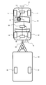
- FIG. 1 is a schematic configuration diagram of a steering control system.
- the vehicle 10 in FIG. 1 is a towing vehicle (tractor) for towing a trailer 50 (towing vehicle).
- the vehicle 10 is a four-wheeled vehicle including a pair of left and right front wheels 11, 11 and a pair of left and right rear wheels 12, 12.
- the vehicle 10 includes a front wheel steering device 14 that controls a steering angle of the front wheels 11 and 11 by an input of a steering wheel (steering wheel) 13 operated by a driver, and a rear wheel 12 according to a command from a steering control device 30 (a steering control unit). , 12 is provided with a rear wheel steering device 16 having a steering actuator for operating the steering angle.
- the steering control device 30 is an electronic control device including a microcomputer having an MPU (Microprocessor Unit), a ROM (Read Only Memory), a RAM (Random Access Memory), and the like.
- the vehicle 10 includes a first external recognition sensor 17 that recognizes a traveling lane or an obstacle in front of the vehicle 10, and a second external recognition sensor 18 that recognizes an obstacle or a trailer 50 behind the vehicle 10.
- the first external recognition sensor 17 and the second external recognition sensor 18 include, for example, a monocular camera and an image processing unit that processes an image of the monocular camera. Acquire recognition information such as objects and trailer movements.
- first external world recognition sensor 17 and the second external world recognition sensor 18 can also obtain recognition information such as a traveling lane, an obstacle, and a trailer motion by a shape recognition device such as a stereo camera or a laser radar.
- the vehicle 10 and the trailer 50 are connected by, for example, a hitch portion 19 (connector) including a hitch ball and a hitch coupler.
- a rolling motion (or a pendulum motion) may occur during traveling due to an influence of an excessive speed, an irregular road surface, a cross wind, and the like. Then, when a rolling motion occurs in the connected vehicle, the trailer 50 vibrates around its vertical axis and vibrates the vehicle 10 via the hitch portion 19, thereby impairing the stability of the connected vehicle. For this reason, the steering control device 30 controls the rear wheel steering angle of the vehicle 10 so as to generate a periodic yaw moment having an opposite phase to the roll motion generated in the coupled vehicle including the vehicle 10 and the trailer 50.
- the trailer stabilization control is performed, and the trailer stabilization control suppresses the roll and stabilizes the connected vehicle.
- FIG. 2 is a configuration block diagram of the steering control device 30.
- the steering control device 30 includes accelerator opening information AO from an accelerator pedal 21 operated by the driver 20, brake opening information BO from a brake pedal 22 operated by the driver 20, and steering wheel 13 operated by the driver 20.
- Driver operation information including angle information is input.
- the steering control device 30 inputs, from the external recognition sensors 17 and 18, information about a traveling lane and an obstacle in front of and behind the vehicle, and information about movement of the trailer 50 behind the vehicle. Further, the steering control device 30 inputs information on the vehicle speed V, which is the vehicle speed of the vehicle 10 from the vehicle speed sensor 23, and information on the longitudinal acceleration and the lateral acceleration from the longitudinal G / lateral G sensor 24.
- the steering control device 30 has functions as an information processing unit 31, a trailer state estimating unit 32, a trailer motion control unit 33, and an actuator control unit 34 for inputting the above various information.
- the information processing unit 31 calculates the motion state of the connected vehicle based on the driver operation information, the outside world recognition information, and the information of the motion state, and further, the vehicle specification information of the vehicle 10 and the trailer 50 stored in the memory.
- the trailer state estimation unit 32 estimates the movement state of the trailer 50 based on the movement state of the connected vehicle calculated by the information processing unit 31.
- the trailer movement control unit 33 generates a control input for stabilizing the movement state of the trailer 50 estimated by the trailer state estimation unit 32.
- the actuator control unit 34 controls the rear wheel steering angle by outputting a steering angle command to the steering actuator of the rear wheel steering device 16 in order to realize the control input generated by the trailer motion control unit 33.
- FIG. 3 is a diagram for explaining the movement of the connected vehicle including the vehicle (tractor) 10 and the trailer 50.
- the yaw rotation Y1 around the center of gravity 10A of the vehicle 10 is mainly caused by the force Ff transmitted from the road surface to the front wheels 11, 11 of the vehicle 10, and the road surface 12 to the rear wheels 12, 12 of the vehicle 10.
- the yaw rotation Y2 about the center of gravity 50A of the trailer 50 is applied to the hitch portion 19 from the trailer 50 side and transmitted to the vehicle 10 and the force Fl transmitted from the road surface to the pair of left and right running wheels 51 and 51 of the trailer 50.
- the magnitudes of the forces Ff and Fr in the vehicle 10 are determined by the motion state of the vehicle 10 such as the front wheel steering angle ⁇ f, the rear wheel steering angle ⁇ r, the side slip angle, and the speed.
- the steering control device 30 outputs the forces Ff and Fr. Is calculated based on the motion state of the vehicle 10, the yaw rate of the vehicle alone can be estimated. Then, the steering control device 30 can estimate the force Fh (external trailer force) by comparing the estimated yaw rate in the case of the vehicle 10 alone with the yaw rate actually generated in the vehicle 10 in the connected vehicle.
- the steering control device 30 determines the motion state of the trailer 50 such as the sideslip angle and speed. From these, the force Fl transmitted from the road surface to the traveling wheels 51, 51 of the trailer 50 can be estimated. As described above, the steering control device 30 estimates the force Fh (external force of the trailer) applied to the hitch portion 19 and the force Fl transmitted from the road surface to the traveling wheels 51, 51 of the trailer 50, thereby obtaining the state of the trailer 50 such as the yaw rate. Can be estimated.
- Fh external force of the trailer
- the steering control device 30 controls the rear wheel steering angle of the vehicle 10 based on the estimation result of the trailer state, thereby manipulating the force Fr transmitted from the road surface to the rear wheels 12, 12 of the vehicle 10, and generating the force on the trailer 50.
- the roll of the connected vehicle is suppressed.
- the control of the rear wheel steering angle by the steering control device 30 is performed in a cycle in which the phase is opposite to the roll motion. Command to generate a typical yaw moment.
- the steering control device 30 can directly obtain the force Fl transmitted from the road surface to the traveling wheels 51, 51 of the trailer 50 from the sensor output.
- FIG. 4 is a control block diagram of the steering control device 30.
- the steering control device 30 first calculates driver operation information 301 such as accelerator opening information AO, brake opening information BO, and steering wheel angle information, and information of a rear wheel steering angle 302 based on vehicle specifications.
- driver operation information 301 such as accelerator opening information AO, brake opening information BO, and steering wheel angle information
- information of a rear wheel steering angle 302 based on vehicle specifications.
- the theoretical vehicle response 304 for the vehicle 10 alone is calculated by inputting it to the vehicle model 303.
- the steering control device 30 responds to the actual vehicle response based on the vehicle motion information (information on the motion status of the vehicle 10) from the on-vehicle sensors 305 (vehicle motion status acquisition unit) such as the vehicle speed sensor 23 and the front / rear G / left / right G sensor 24. 306 is requested. Then, the steering control device 30 estimates the trailer external force 307 applied to the vehicle 10 (the force Fh applied to the hitch 19 from the trailer 50 side and transmitted to the vehicle 10) based on the difference between the theoretical vehicle response 304 and the actual vehicle response 306. .
- vehicle motion information information on the motion status of the vehicle 10
- the on-vehicle sensors 305 vehicle motion status acquisition unit
- the steering control device 306 estimates the trailer external force 307 applied to the vehicle 10 (the force Fh applied to the hitch 19 from the trailer 50 side and transmitted to the vehicle 10) based on the difference between the theoretical vehicle response 304 and the actual vehicle response 306. .
- the steering control device 30 estimates a trailer state 308 such as a force applied to the trailer 50 and a yaw moment based on the trailer external force 307 and the motion of the trailer 50 recognized by the external recognition sensor 18. Then, the steering control device 30 calculates a yaw moment for suppressing the yaw motion of the trailer 50 by the trailer motion control 309, and calculates the yaw moment for suppressing the yaw motion of the trailer 50 by changing the rear wheel steering angle 302. To be generated.
- a trailer state 308 such as a force applied to the trailer 50 and a yaw moment based on the trailer external force 307 and the motion of the trailer 50 recognized by the external recognition sensor 18. Then, the steering control device 30 calculates a yaw moment for suppressing the yaw motion of the trailer 50 by the trailer motion control 309, and calculates the yaw moment for suppressing the yaw motion of the trailer 50 by changing the rear wheel steering angle 302. To be generated.
- the steering control device 30 suppresses the yaw moment of the trailer 50. Is generated by rear wheel steering, and the yaw motion of the trailer 50 is reduced.
- the steering control device 30 can measure the trailer motion by using a yaw rate sensor, an acceleration sensor, a sensor that measures the angle of the hitch 19, or the like mounted on the trailer 50.
- FIG. 5 shows a three-wheel vehicle model.
- x, y, and z are coordinate axes of the coordinate system of the vehicle 10.
- the positive direction of the coordinate axis x is the forward direction of the vehicle 10
- the positive direction of the coordinate axis y is the left direction of the vehicle 10
- the positive direction of the coordinate axis z is the upward direction of the vehicle 10.
- xt, yt, and zt are coordinate axes of the coordinate system of the trailer 50.
- the positive direction of the coordinate axis xt is the forward direction of the trailer 50
- the positive direction of the coordinate axis yt is the leftward direction of the trailer 50
- the positive direction of the coordinate axis zt is the upward direction of the trailer 50.
- Lf is the distance between the front wheels 11, 11 and the vehicle center of gravity 10A
- Lr is the distance between the rear wheels 12, 12 and the vehicle center of gravity 10A
- Lh is the distance between the hitch 19 and the vehicle center of gravity 10A
- Lth is the distance between the hitch 19 and the vehicle.
- the distance between the trailer center of gravity 50A and Ltr is the distance between the running wheels 51 and 51 of the trailer 50 and the trailer center of gravity 50A.
- mv is the mass of the vehicle 10
- Jvzz is the yaw moment of inertia of the vehicle 10
- ⁇ is the yaw angle of the vehicle 10 (dot is the yaw angular velocity)
- mt is the mass of the trailer 50
- Jtzz is the yaw moment of inertia of the trailer 50
- ⁇ t is The yaw angle of the trailer 50 (dot is the yaw angular velocity).
- ⁇ f is the steering angle of the front wheels 11 of the vehicle 10
- ⁇ r is the steering angle of the rear wheels 12 of the vehicle 10.
- fxf is the vertical tire force of the front wheels 11, 11 of the vehicle 10
- the forward direction is the forward direction of the vehicle 10.
- fyf is defined by the tire force in the lateral direction of the front wheels 11, 11 of the vehicle 10 and the forward direction is defined as the left direction of the vehicle 10.
- fxr is the forward direction of the vehicle 10 in the forward direction due to the tire force in the vertical direction of the rear wheels 12, 12 of the vehicle 10.
- fyr is defined by the tire force in the lateral direction of the rear wheels 12 and 12 of the vehicle 10 and the forward direction is set to the left direction of the vehicle 10.
- fxh is a vertical hitch force and the forward direction is a forward direction
- fyh is a horizontal hitch force and a forward direction is a left direction
- Fxt is a vertical tire of the running wheels 51 and 51 of the trailer 50.
- the forward direction is the forward direction of the trailer 50 by force
- fyt is the leftward direction of the trailer 50 by the tire force in the lateral direction of the running wheels 51, 51 of the trailer 50.
- ⁇ is a hitch angle.
- Equation 1 The equation of motion of the vehicle 10 is as shown in Equation 1.
- Equation 3 the equation of motion is defined as in Equation 3. Note that each variable in Equation 3 is as shown in Equation 4.
- the steering control device 30 can estimate the motion of the trailer 50 according to Expression 6 by using the estimation result by the observer (state estimator) in Expression 5. Then, the steering control device 30 performs trailer stabilization control (rear wheel steering control) based on the estimated motion of the trailer 50.
- trailer stabilization control rear wheel steering control
- FIG. 6 is a flowchart showing the procedure of the trailer stabilization control.
- the steering control device 30 obtains driver operation information such as the front wheel steering angle ⁇ f.
- the steering control device 30 acquires vehicle motion information (vehicle sensor information) such as the yaw rate and the vehicle speed of the vehicle 10 detected by the vehicle-mounted sensor.
- vehicle motion information vehicle sensor information
- step S503 the steering control device 30 calculates a theoretical vehicle response based on the driver's operation information acquired in step S501, and calculates an actual vehicle response based on the vehicle motion information (in-vehicle sensor information) acquired in step S502. Then, a difference between the theoretical vehicle response and the actual vehicle response is determined. Then, in step S504, the steering control device 30 determines a trailer external force (the force Fh applied to the hitch portion 19 from the trailer 50 side and transmitted to the vehicle 10) based on the difference between the theoretical vehicle response and the actual vehicle response.
- a trailer external force the force Fh applied to the hitch portion 19 from the trailer 50 side and transmitted to the vehicle
- the steering control device 30 acquires information on the relative position of the trailer 50 with respect to the vehicle 10 by the external recognition sensor 18 in step S505. Then, in step S506, the steering control device 30 estimates a trailer state such as the yaw rate of the trailer 50 based on the trailer external force obtained in step S504 and the relative position between the vehicle 10 and the trailer 50.
- step S507 the steering control device 30 obtains a difference between the yaw rate of the vehicle 10 and the yaw rate of the trailer 50, and determines whether or not the absolute value of the difference exceeds a threshold.
- the steering control device 30 if the absolute value of the difference between the yaw rate of the vehicle 10 and the yaw rate of the trailer 50 does not exceed the threshold, the steering control device 30 returns to step S501 and does not execute the trailer stabilization control.
- step S508 a hitch force (trailer motion compensation hitch force) for suppressing the yaw motion of the trailer 50 is obtained.
- step S509 the steering control device 30 proceeds to step S509, and obtains a target rear wheel steering angle ⁇ r for generating the hitch force obtained in step S508.
- the steering control device 30 proceeds to step S510, and controls the rear wheel steering device 16 (steering actuator) based on the target rear wheel steering angle ⁇ r obtained in step S509.
- the steering control device 30 controls the motion of the trailer 50 such that the difference between the yaw rate of the vehicle 10 and the yaw rate of the trailer 50 is reduced by the rear wheel steering control.
- FIG. 7 is a time chart illustrating changes in the yaw rate and the rear wheel steering angle when the steering control device 30 performs the trailer stabilization control.
- the theoretical vehicle yaw rate (theoretical vehicle response) of the vehicle 10 alone calculated by the steering control device 30 based on the vehicle speed and vehicle specifications becomes the front wheel steering angle ⁇ f.
- the response changes in accordance with the change in.
- the actual yaw rate of the vehicle 10 shows a different behavior from the theoretical vehicle yaw rate when the vehicle 10 receives an external force from the trailer 50 (trailer external force).
- the actual yaw rate of the vehicle 10 also changes periodically because the trailer external force changes periodically.
- the estimated value of the yaw rate of the trailer 50 obtained by the steering control device 30 indicates a variation according to the trailer external force.
- the steering control device 30 calculates a difference between the theoretical vehicle yaw rate and the estimated trailer yaw rate, and when the difference exceeds a threshold value, generates a periodic yaw moment having an opposite phase to the roll motion in rear wheel steering. Outputs the angle command.
- the yaw rate of the trailer 50 is stabilized.
- the steering angle of the rear wheels 12, 12 is controlled, so that a change in the speed of the vehicle 10 due to the trailer stabilization control can be suppressed. Further, since the yaw moment that can be generated by controlling the rear wheel steering angle is larger than the yaw moment that can be generated by the automatic brake, a larger trailer 50 can be generated than when the yaw moment is generated by the automatic brake. It is possible to stabilize the running of the vehicle 10 to which the vehicle is connected.
- the trailer stabilization control system can suppress the yaw motion of the trailer 50 by the rear wheel steering control and the automatic brake control by the steering control device 30.
- the trailer stabilization control system When the yaw moment that can be generated by the rear wheel steering control by the steering control device 30 is insufficient to suppress the yaw motion of the trailer 50, the trailer stabilization control system generates the yaw moment generated by the automatic brake. Can be added.
- the present invention is not limited to the above-described embodiment, and includes various modifications.
- the above-described embodiments have been described in detail for easy understanding of the present invention, and are not necessarily limited to those having all the configurations described above.
- a part of the configuration of one embodiment can be replaced with the configuration of another embodiment, and the configuration of one embodiment can be added to the configuration of another embodiment.
Landscapes
- Engineering & Computer Science (AREA)
- Chemical & Material Sciences (AREA)
- Combustion & Propulsion (AREA)
- Transportation (AREA)
- Mechanical Engineering (AREA)
- Physics & Mathematics (AREA)
- Mathematical Physics (AREA)
- Theoretical Computer Science (AREA)
- Steering Control In Accordance With Driving Conditions (AREA)
- Steering-Linkage Mechanisms And Four-Wheel Steering (AREA)
- Control Of Driving Devices And Active Controlling Of Vehicle (AREA)
Abstract
Le dispositif de commande de direction, le procédé de commande de direction et le système de commande de direction selon la présente invention impliquent l'émission d'une commande pour générer des moments de lacet périodiques, qui sont en opposition de phase avec un mouvement de roulis d'un côté à l'autre généré dans des véhicules combinés comprenant un véhicule et une remorque, à un dispositif de direction de roue arrière qui commande l'angle de direction des roues arrière du véhicule.
Priority Applications (3)
| Application Number | Priority Date | Filing Date | Title |
|---|---|---|---|
| US17/272,833 US12179836B2 (en) | 2018-09-03 | 2019-08-02 | Steering control apparatus, steering control method, and steering control system |
| CN201980054630.8A CN112770959B (zh) | 2018-09-03 | 2019-08-02 | 转向控制装置、转向控制方法以及转向控制系统 |
| DE112019004416.8T DE112019004416B4 (de) | 2018-09-03 | 2019-08-02 | Lenksteuervorrichtung, lenksteuerverfahren und lenksteuersystem |
Applications Claiming Priority (2)
| Application Number | Priority Date | Filing Date | Title |
|---|---|---|---|
| JP2018-164588 | 2018-09-03 | ||
| JP2018164588A JP7152906B2 (ja) | 2018-09-03 | 2018-09-03 | 操舵制御装置、操舵制御方法、及び操舵制御システム |
Publications (1)
| Publication Number | Publication Date |
|---|---|
| WO2020049919A1 true WO2020049919A1 (fr) | 2020-03-12 |
Family
ID=69722805
Family Applications (1)
| Application Number | Title | Priority Date | Filing Date |
|---|---|---|---|
| PCT/JP2019/030448 Ceased WO2020049919A1 (fr) | 2018-09-03 | 2019-08-02 | Dispositif de commande de direction, procédé de commande de direction et système de commande de direction |
Country Status (5)
| Country | Link |
|---|---|
| US (1) | US12179836B2 (fr) |
| JP (1) | JP7152906B2 (fr) |
| CN (1) | CN112770959B (fr) |
| DE (1) | DE112019004416B4 (fr) |
| WO (1) | WO2020049919A1 (fr) |
Cited By (2)
| Publication number | Priority date | Publication date | Assignee | Title |
|---|---|---|---|---|
| WO2022111801A1 (fr) * | 2020-11-25 | 2022-06-02 | Volvo Truck Corporation | Procédé de commande d'une combinaison de véhicules |
| CN115230716A (zh) * | 2022-06-30 | 2022-10-25 | 上海西井信息科技有限公司 | 牵引车与拖挂的偏航角预测方法、系统、设备及存储介质 |
Families Citing this family (6)
| Publication number | Priority date | Publication date | Assignee | Title |
|---|---|---|---|---|
| JP7405660B2 (ja) * | 2020-03-19 | 2023-12-26 | Lineヤフー株式会社 | 出力装置、出力方法及び出力プログラム |
| KR102937738B1 (ko) * | 2020-06-23 | 2026-03-13 | 현대자동차주식회사 | 굴절 차량용 굴절 제어 장치 및 그의 굴절 제어 방법 |
| US11814098B2 (en) * | 2021-03-11 | 2023-11-14 | GM Global Technology Operations LLC | Methods, systems, and apparatuses for identification and compensation of trailer impacts on steering dynamics for automated driving |
| DE102024117514A1 (de) * | 2024-06-21 | 2025-12-24 | Bayerische Motoren Werke Aktiengesellschaft | Verfahren zum Stabilisieren eines Fahrzustandes eines gleislosen Gespanns aus einem Zugfahrzeug und einem Anhänger |
| JP2026054071A (ja) * | 2024-09-13 | 2026-03-26 | 株式会社ジェイテクト | 連結車両の制御装置、連結車両の制御方法、および連結車両の制御プログラム |
| EP4725721A1 (fr) | 2024-10-11 | 2026-04-15 | Aisin Corporation | Dispositif d'aide à la conduite |
Citations (6)
| Publication number | Priority date | Publication date | Assignee | Title |
|---|---|---|---|---|
| JPH0467183U (fr) * | 1990-10-17 | 1992-06-15 | ||
| JPH08150951A (ja) * | 1994-11-30 | 1996-06-11 | Mitsubishi Motors Corp | 連結車のトラクタ後輪操舵制御方法及びその装置 |
| JPH09267762A (ja) * | 1996-04-01 | 1997-10-14 | Mitsubishi Motors Corp | トレーラの車輪操舵制御方法及びその装置 |
| JP2003503276A (ja) * | 1999-06-30 | 2003-01-28 | ロベルト・ボッシュ・ゲゼルシャフト・ミト・ベシュレンクテル・ハフツング | 自動車の安定化方法および装置 |
| JP2009012488A (ja) * | 2007-06-29 | 2009-01-22 | Honda Motor Co Ltd | 連結車両の運動安定化装置 |
| WO2010087022A1 (fr) * | 2009-02-02 | 2010-08-05 | トヨタ自動車株式会社 | Dispositif de commande de comportement pour ensemble tracteur/remorque |
Family Cites Families (13)
| Publication number | Priority date | Publication date | Assignee | Title |
|---|---|---|---|---|
| DE4127750C1 (en) * | 1991-08-22 | 1992-09-03 | Mercedes-Benz Aktiengesellschaft, 7000 Stuttgart, De | Automotive equipment improving stability of car and trailer linkage - uses sensors or measurement value pick=ups to register undesired swing of trailer and automatic auxiliary linkage to counteract it |
| DE19964048A1 (de) * | 1999-06-30 | 2001-01-04 | Bosch Gmbh Robert | Verfahren und Einrichtung zum Stabilisieren eines Straßenfahrzeugs |
| DE102004004151B4 (de) * | 2004-01-28 | 2014-11-27 | Robert Bosch Gmbh | Verfahren und Vorrichtung zur Erkennung und Stabilisierung eines schlingernden Anhängers mittels Radkräften |
| US7640089B2 (en) * | 2005-04-06 | 2009-12-29 | Gm Global Technology Operations, Inc. | Vehicle-trailer stability and handling performance improvement using rear-wheel steering control |
| US8380390B2 (en) * | 2009-06-24 | 2013-02-19 | Robert Bosch Gmbh | Method and system of determining load characteristics of a trailer |
| DE112010005216B4 (de) * | 2010-02-02 | 2017-02-02 | Toyota Jidosha Kabushiki Kaisha | Fahrzeugverhaltenssteuervorrichtung |
| US8700282B2 (en) * | 2011-07-28 | 2014-04-15 | Advics Co., Ltd. | Method and apparatus for vehicle sway detection and reduction |
| DE102012222862A1 (de) * | 2012-12-12 | 2014-06-12 | Robert Bosch Gmbh | Verfahren und Vorrichtung zur Stabilisierung eines aus einem Zugfahrzeug und einem Anhänger bestehenden Fahrzeuggespanns |
| JP6069148B2 (ja) * | 2013-09-19 | 2017-02-01 | 日立オートモティブシステムズ株式会社 | 車両制御装置 |
| US20160318493A1 (en) * | 2014-03-10 | 2016-11-03 | Dean Drako | Anti-jackknifing apparatus for articulated vehicles |
| DE102014211268B4 (de) * | 2014-06-12 | 2024-11-28 | Bayerische Motoren Werke Aktiengesellschaft | Verfahren und Gespann-Stabilisationsvorrichtung zum Stabilisieren des Schlingerverhaltens eines Gespanns und Gespann |
| CN105292251A (zh) * | 2015-11-11 | 2016-02-03 | 吉林大学 | 一种适用于汽车的四轮转向系统 |
| US9873426B2 (en) * | 2016-06-21 | 2018-01-23 | Ford Global Technologies, Llc | System for mitigating vehicle sway |
-
2018
- 2018-09-03 JP JP2018164588A patent/JP7152906B2/ja active Active
-
2019
- 2019-08-02 US US17/272,833 patent/US12179836B2/en active Active
- 2019-08-02 DE DE112019004416.8T patent/DE112019004416B4/de active Active
- 2019-08-02 CN CN201980054630.8A patent/CN112770959B/zh active Active
- 2019-08-02 WO PCT/JP2019/030448 patent/WO2020049919A1/fr not_active Ceased
Patent Citations (6)
| Publication number | Priority date | Publication date | Assignee | Title |
|---|---|---|---|---|
| JPH0467183U (fr) * | 1990-10-17 | 1992-06-15 | ||
| JPH08150951A (ja) * | 1994-11-30 | 1996-06-11 | Mitsubishi Motors Corp | 連結車のトラクタ後輪操舵制御方法及びその装置 |
| JPH09267762A (ja) * | 1996-04-01 | 1997-10-14 | Mitsubishi Motors Corp | トレーラの車輪操舵制御方法及びその装置 |
| JP2003503276A (ja) * | 1999-06-30 | 2003-01-28 | ロベルト・ボッシュ・ゲゼルシャフト・ミト・ベシュレンクテル・ハフツング | 自動車の安定化方法および装置 |
| JP2009012488A (ja) * | 2007-06-29 | 2009-01-22 | Honda Motor Co Ltd | 連結車両の運動安定化装置 |
| WO2010087022A1 (fr) * | 2009-02-02 | 2010-08-05 | トヨタ自動車株式会社 | Dispositif de commande de comportement pour ensemble tracteur/remorque |
Cited By (3)
| Publication number | Priority date | Publication date | Assignee | Title |
|---|---|---|---|---|
| WO2022111801A1 (fr) * | 2020-11-25 | 2022-06-02 | Volvo Truck Corporation | Procédé de commande d'une combinaison de véhicules |
| US12545236B2 (en) | 2020-11-25 | 2026-02-10 | Volvo Truck Corporation | Method of controlling a vehicle combination |
| CN115230716A (zh) * | 2022-06-30 | 2022-10-25 | 上海西井信息科技有限公司 | 牵引车与拖挂的偏航角预测方法、系统、设备及存储介质 |
Also Published As
| Publication number | Publication date |
|---|---|
| CN112770959B (zh) | 2023-06-02 |
| JP7152906B2 (ja) | 2022-10-13 |
| US20210347409A1 (en) | 2021-11-11 |
| JP2020037301A (ja) | 2020-03-12 |
| DE112019004416B4 (de) | 2025-04-17 |
| DE112019004416T5 (de) | 2021-05-27 |
| CN112770959A (zh) | 2021-05-07 |
| US12179836B2 (en) | 2024-12-31 |
Similar Documents
| Publication | Publication Date | Title |
|---|---|---|
| JP7152906B2 (ja) | 操舵制御装置、操舵制御方法、及び操舵制御システム | |
| JP7165204B2 (ja) | 操舵制御装置、操舵制御方法、及び操舵制御システム | |
| CN101288081B (zh) | 车辆横摆稳定系统 | |
| EP1574386B1 (fr) | Système de contrôle de la stabilité d'un véhicule | |
| US8010252B2 (en) | Trailer oscillation detection and compensation method for a vehicle and trailer combination | |
| JP6926210B2 (ja) | 自動車線変更中の横方向位置偏差の低減 | |
| JP4631549B2 (ja) | 車両運動安定化制御装置 | |
| US8359155B2 (en) | Vehicle driving operation support apparatus/method and vehicle | |
| JP5227082B2 (ja) | 4輪操舵機構を搭載した車両の操舵制御装置 | |
| WO2019166142A1 (fr) | Procédés et appareil d'acquisition et de suivi, de classification d'objets et d'inférence de terrain | |
| KR20210018731A (ko) | 트레일러 장착 차량의 주행 지원 장치, 그를 포함한 시스템 및 그 방법 | |
| GB2571589A (en) | Terrain inference method and apparatus | |
| JP2007022117A (ja) | 車両安定化制御システム | |
| JP4600339B2 (ja) | 障害物回避制御装置及び障害物回避制御プログラム | |
| JP3271956B2 (ja) | 車両の路面摩擦係数推定装置 | |
| JP2001354124A (ja) | 車両の走行安全装置 | |
| JP2024123479A (ja) | 車体すべり角推定方法、車体すべり角推定プログラム、及び車両制御装置 | |
| CN118144797A (zh) | 自动驾驶中超过大型车辆时对拉力影响的识别和减轻控制 | |
| WO2026063233A1 (fr) | Système d'aide à la conduite, procédé d'aide à la conduite et programme d'aide à la conduite | |
| CN120792809A (zh) | 一种自动紧急避让方法、介质、程序、控制器和车辆 |
Legal Events
| Date | Code | Title | Description |
|---|---|---|---|
| 121 | Ep: the epo has been informed by wipo that ep was designated in this application |
Ref document number: 19856897 Country of ref document: EP Kind code of ref document: A1 |
|
| 122 | Ep: pct application non-entry in european phase |
Ref document number: 19856897 Country of ref document: EP Kind code of ref document: A1 |
|
| WWG | Wipo information: grant in national office |
Ref document number: 112019004416 Country of ref document: DE |