WO2020049960A1 - Véhicule de transport - Google Patents
Véhicule de transport Download PDFInfo
- Publication number
- WO2020049960A1 WO2020049960A1 PCT/JP2019/031756 JP2019031756W WO2020049960A1 WO 2020049960 A1 WO2020049960 A1 WO 2020049960A1 JP 2019031756 W JP2019031756 W JP 2019031756W WO 2020049960 A1 WO2020049960 A1 WO 2020049960A1
- Authority
- WO
- WIPO (PCT)
- Prior art keywords
- frame
- body frames
- pair
- lifter
- carrier according
- Prior art date
- Legal status (The legal status is an assumption and is not a legal conclusion. Google has not performed a legal analysis and makes no representation as to the accuracy of the status listed.)
- Ceased
Links
Images


Classifications
-
- B—PERFORMING OPERATIONS; TRANSPORTING
- B60—VEHICLES IN GENERAL
- B60P—VEHICLES ADAPTED FOR LOAD TRANSPORTATION OR TO TRANSPORT, TO CARRY, OR TO COMPRISE SPECIAL LOADS OR OBJECTS
- B60P1/00—Vehicles predominantly for transporting loads and modified to facilitate loading, consolidating the load, or unloading
- B60P1/02—Vehicles predominantly for transporting loads and modified to facilitate loading, consolidating the load, or unloading with parallel up-and-down movement of load supporting or containing element
-
- B—PERFORMING OPERATIONS; TRANSPORTING
- B66—HOISTING; LIFTING; HAULING
- B66F—HOISTING, LIFTING, HAULING OR PUSHING, NOT OTHERWISE PROVIDED FOR, e.g. DEVICES WHICH APPLY A LIFTING OR PUSHING FORCE DIRECTLY TO THE SURFACE OF A LOAD
- B66F3/00—Devices, e.g. jacks, adapted for uninterrupted lifting of loads
- B66F3/02—Devices, e.g. jacks, adapted for uninterrupted lifting of loads with racks actuated by pinions
-
- B—PERFORMING OPERATIONS; TRANSPORTING
- B61—RAILWAYS
- B61B—RAILWAY SYSTEMS; EQUIPMENT THEREFOR NOT OTHERWISE PROVIDED FOR
- B61B13/00—Other railway systems
-
- B—PERFORMING OPERATIONS; TRANSPORTING
- B62—LAND VEHICLES FOR TRAVELLING OTHERWISE THAN ON RAILS
- B62B—HAND-PROPELLED VEHICLES, e.g. HAND CARTS OR PERAMBULATORS; SLEDGES
- B62B3/00—Hand carts having more than one axis carrying transport wheels; Steering devices therefor; Equipment therefor
-
- B—PERFORMING OPERATIONS; TRANSPORTING
- B62—LAND VEHICLES FOR TRAVELLING OTHERWISE THAN ON RAILS
- B62B—HAND-PROPELLED VEHICLES, e.g. HAND CARTS OR PERAMBULATORS; SLEDGES
- B62B3/00—Hand carts having more than one axis carrying transport wheels; Steering devices therefor; Equipment therefor
- B62B3/04—Hand carts having more than one axis carrying transport wheels; Steering devices therefor; Equipment therefor involving means for grappling or securing in place objects to be carried; Loading or unloading equipment
- B62B3/06—Hand carts having more than one axis carrying transport wheels; Steering devices therefor; Equipment therefor involving means for grappling or securing in place objects to be carried; Loading or unloading equipment for simply clearing the load from the ground
-
- B—PERFORMING OPERATIONS; TRANSPORTING
- B66—HOISTING; LIFTING; HAULING
- B66F—HOISTING, LIFTING, HAULING OR PUSHING, NOT OTHERWISE PROVIDED FOR, e.g. DEVICES WHICH APPLY A LIFTING OR PUSHING FORCE DIRECTLY TO THE SURFACE OF A LOAD
- B66F9/00—Devices for lifting or lowering bulky or heavy goods for loading or unloading purposes
- B66F9/06—Devices for lifting or lowering bulky or heavy goods for loading or unloading purposes movable, with their loads, on wheels or the like, e.g. fork-lift trucks
- B66F9/063—Automatically guided
Definitions
- the present invention relates to a transport vehicle, and particularly to a transport vehicle having a lifter.
- Patent Literature 1 discloses, for example, a forklift 2.
- the forklift 2 has a pair of left and right side frames 4 and 6 and a rear frame 8.
- a conventional lifter-equipped transport vehicle can lift and transport a heavy object (for example, about 1000 kg). It is necessary to reinforce the main frame in order to cope with such a large load, but the reinforcement of the main frame increases the size of the body. As the size of the body increases, the weight of the entire transport vehicle increases, and the size of the battery and motor also need to be increased. Further, in the conventional lifter-equipped transport vehicle, the main frame and the lifter frame are separately configured, so that the frame is doubled, so that there is no useless space to secure the space for the mounting portion. Had occurred.
- An object of the present invention is to reduce the size of a transporter with a lifter.
- a transport vehicle includes a pair of left and right body frames, drive wheels, auxiliary wheels, and a lifter mechanism.
- the pair of left and right body frames extend in the front-rear direction.
- the drive wheels are arranged at the center in the front-rear direction of each body frame. Therefore, the number of drive wheels is two in total.
- the auxiliary wheels are arranged at the front and rear ends and lower portions of each body frame. Therefore, the number of auxiliary wheels is four in total.
- the lifter mechanism is disposed at an end and an upper part in the front-rear direction of each body frame. Therefore, the number of lifter mechanisms is four in total.
- the place where the lifter mechanism is mounted is a frame that supports the drive wheels and the auxiliary wheels. Therefore, the lifter mechanism and the frame can be integrated, so that the carrier can be reduced in size and weight.
- the lifter mechanism and the auxiliary wheels are further provided at the front and rear ends of each body frame, the lifter mechanism is arranged near the auxiliary wheels. For this reason, a large load is less likely to act on portions other than the ends of the frame, so that the carrier can be reduced in size and weight.
- the positions of the auxiliary wheels and the lifter mechanism in plan view may be the same or different.
- the carrier may further include a connection frame and a lower frame.
- the connection frame may connect the upper portions of the pair of left and right body frames.
- the lower frame may be disposed between the pair of left and right body frames, and may be detachably fixed to lower portions of the pair of left and right body frames. In this transport vehicle, since the body frame and the lower frame have a divided structure, access to components disposed inside is facilitated.
- connection frame may connect the middle of the pair of left and right body frames in the front-rear direction.
- this carrier sufficient strength can be obtained with a frame having a simple structure.
- the entire body is easily bent because the pair of left and right body frames are connected only at the middle in the front-rear direction. Stress is distributed.
- Each of the lifter mechanisms may further include a lifting motor, a lifting transmission shaft, and a bearing.
- the elevating motor may be arranged above the vehicle body frame or the connection frame.
- the lifting transmission shaft may be moved up and down by being driven by a lifting motor.
- the bearing may support the elevating transmission shaft so as to be vertically movable. In this transport vehicle, the transport vehicle can be further miniaturized by supporting the lifting motor by the body frame or the connection frame.
- the transport vehicle may further include electrical components arranged on the upper surface of the lower frame at a position different from the connection frame in a plan view.
- electrical components arranged on the upper surface of the lower frame at a position different from the connection frame in a plan view.
- this transport vehicle by arranging the electrical components at different positions in plan view from the connection frame, at least a part of the electrical components and the connection frame can be arranged at the same height position. Can be compact.
- the lower frame may be able to separate downward as an integral member when being removed from the pair of left and right body frames.
- the lower frame and the electrical components can be separated downward from the body frame by a single operation by forming the body frame and the lower frame into a divided structure. Therefore, maintainability is improved. Further, at the time of assembling work, the process of the body frame and the process of the lower frame can be performed in parallel, so that the manufacturing period can be shortened.
- Each body frame may include a main body on which the lifter mechanism is mounted, and a reinforcing portion extending downward from the main body.
- the strength is improved while the weight is maintained by the body frame having the reinforcing portion.
- the carrier with the lifter is reduced in size.
- FIG. 2 is a schematic perspective view of the carrier according to the first embodiment.
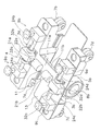
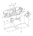
- FIG. 3 is a schematic perspective view showing a frame and a lifter mechanism of the transport vehicle.
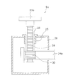
- FIG. 4 is a schematic sectional view of a lifter mechanism.
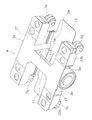
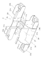
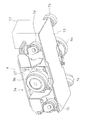
- FIG. 3 is a schematic perspective view showing a frame of the transport vehicle. The typical perspective view which looked at the frame from the lower side.
- FIG. 2 is a schematic plan view showing a positional relationship between a frame and electrical components.
- FIG. 4 is a schematic perspective view of the lower frame assembled to the vehicle body frame as viewed from below.
- FIG. 4 is a schematic perspective view of the lower frame removed from the vehicle body frame as viewed from below.
- FIG. 1 is a schematic perspective view of the carrier according to the first embodiment.
- FIG. 2 is a schematic perspective view showing a frame and a lifter mechanism of the transport vehicle.
- FIG. 3 is a schematic sectional view of the lifter mechanism.
- the transport vehicle 1 is a device for transporting a load.
- the transport vehicle 1 can transport the load to the transfer position and move up and down. Further, the transport vehicle 1 can rotate the load about a vertical axis.
- the transport vehicle 1 includes a pair of left and right body frames 3a, 3b, drive wheels 5a, 5b, auxiliary wheels 7a, 7b, 7c, 7d, and lifter mechanisms 9a, 9b, 9c, 9d.
- a pair of left and right body frames 3a, 3b extend in the front-back direction in the first direction, and are separated from each other in the second direction orthogonal to the front-rear direction.
- the body frames 3a and 3b are formed from thin plate members.
- the drive wheels 5a and 5b are respectively arranged at the center of the body frames 3a and 3b in the first direction. Therefore, the number of drive wheels is two in total.
- the first direction which is the side on which the drive wheels 5a and 5b face, is the traveling direction.
- the transport vehicle 1 has traveling motors 8a and 8b.
- the traveling motors 8a and 8b are of a direct drive type disposed in the driving wheels 5a and 5b, respectively.
- the traveling motor 8a is hidden and does not appear in the drawing.
- the auxiliary wheels 7a, 7b, 7c, 7d are arranged at the lower end and in the first direction of the body frames 3a, 3b.
- the auxiliary wheel 7a is provided at the front end of the vehicle body frame 3a
- the auxiliary wheel 7b is provided at the rear end of the vehicle body frame 3a
- the auxiliary wheel 7c is provided at the front end of the vehicle body frame 3b
- 7d is provided at the rear end of the body frame 3b.
- the auxiliary wheel is, for example, a caster wheel, and is also rotatable around a vertical axis.
- the auxiliary wheels 7a to 7d receive most of the load and the load of the transport vehicle 1, and the load received by one of the drive wheels 5a, 5b is equal to the load received by one of the auxiliary wheels 7a to 7d. It is on the order of a fraction.
- the drive wheels 5a and 5b are respectively urged downward by springs (not shown).
- the lifter mechanisms 9a to 9d are mechanisms for raising and lowering a load. Specifically, the lifter mechanisms 9a to 9d are arranged at the ends and upper portions of the body frames 3a, 3b in the first direction. More specifically, a lifter mechanism 9a is provided at a front end of the vehicle body frame 3a, a lifter mechanism 9b is provided at a rear end of the vehicle body frame 3a, and a lifter mechanism 9c is provided at a front end of the vehicle body frame 3b. A mechanism 9d is provided at the rear end of the body frame 3b. In this embodiment, the corresponding auxiliary wheels are arranged to be shifted outward in the first direction with respect to the lifter mechanism.
- the auxiliary wheel is positioned outside the lifter mechanism because the support by the auxiliary wheel is stabilized.
- the positions of the auxiliary wheels and the lifter mechanism in plan view may be the same, or they may be shifted inward in the first direction.
- the auxiliary wheels may be arranged with respect to the lifter mechanism not in the first direction but in the second direction, and shifted in both the first direction and the second direction. The advantage of shifting the auxiliary wheel with respect to the lifter mechanism in a plan view is to secure a space in which the lifting transmission shaft of the lifter mechanism moves in the vertical direction.
- the places where the lifter mechanisms 9a to 9d are mounted are the vehicle body frames 3a and 3b that support the drive wheels 5a and 5b and the auxiliary wheels 7a to 7d. Therefore, the lifter mechanisms 9a to 9d can be integrated with the body frames 3a and 3b, and the size and weight of the carrier 1 can be reduced.
- the lifter mechanisms 9a to 9d and the auxiliary wheels 7a to 7d are further provided at the ends of the body frames 3a and 3b in the first direction, so that the lifter mechanisms 9a to 9d are connected to the auxiliary wheels 7a to 7d. In the vicinity of. For this reason, a large load is less likely to act on portions other than the end portions of the body frames 3a, 3b, so that the carrier 1 can be reduced in size and weight.
- the carrier 1 further includes a connection frame 11.
- the connection frame 11 is a thin plate member, and connects upper portions of a pair of left and right body frames 3a, 3b. Specifically, as shown in FIGS. 4 and 5, the connection frame 11 has a thin plate portion 11a extending in the second direction and continuing to the upper surfaces of the pair of left and right body frames 3a, 3b.
- the connection frame 11 has, in addition to the thin plate portion 11a, other members that reinforce the connection between the pair of left and right body frames 3a, 3b.
- the connection frame 11 further has a pair of ribs 11b.
- the pair of ribs 11b are thin plate members that are fixed to lower portions at both ends in the first direction of the thin plate portion 11a and extend in the second direction.
- connection frame 11 has a reinforcing member 11c.
- the reinforcing member 11c is disposed between the pair of ribs 11b at a lower portion of both ends of the thin plate portion 11a in the second direction.
- the reinforcing member 11c is fixed to the thin plate portion 11a and the pair of ribs 11b, and is further fixed to the first reinforcing portion 29.
- the H-shaped upper frame 4 is formed by the pair of left and right body frames 3a and 3b and the connection frame 11.
- the portion where the connection frame 11 is connected is the middle of the pair of left and right body frames 3a and 3b in the first direction. Therefore, in the carrier 1, sufficient strength can be obtained with a frame having a simple structure. In particular, even if a large force is applied partially when the transport vehicle 1 passes through unevenness on the floor, the entire body bends because the pair of left and right body frames 3a and 3b are connected only at the middle in the first direction. The stress is dispersed. Further, since the lifter mechanisms 9a to 9d are provided at the four corners (the corners or corners of the H-shaped upper frame 4) in plan view of the carrier 1, a large size is provided between the pair of left and right body frames 3a, 3b. Space is secured. For this reason, the arrangement of the electrical component 17 described later is facilitated.
- the transport vehicle 1 has lifting motors 21a and 21b as a part of the lifter mechanism or a device for driving the lifter mechanism.
- the elevating motors 21 a and 21 b are provided on the connection frame 11.
- the transport vehicle 1 has distribution mechanisms 22a and 22b that distribute the power of the elevating motors 21a and 21b in two directions.
- the transport vehicle 1 has drive shafts 24a and 24b extending from the distribution mechanism 22a toward the lifter mechanisms 9a and 9b, respectively.
- the drive shafts 24a and 24b are rotatably supported by bearings 32a and 32b provided on the upper surface of the body frame 3a.
- the transport vehicle 1 has drive shafts 24c and 24d extending from the distribution mechanism 22b toward the lifter mechanisms 9c and 9d, respectively.
- the drive shafts 24c and 24d are rotatably supported by bearings 32c and 32d provided on the upper surface of the body frame 3a.
- the lifter mechanism 9a has a lifting transmission shaft 23.
- the lifting transmission shaft 23 is a member that moves up and down, and extends vertically in the vertical direction.
- the lifting transmission shaft 23 has a flat plate portion 23a on the upper part.
- the lifting transmission shaft 23 is supported by a bearing 25 supported by a housing 26 of the lifter mechanism 9a so as to be vertically movable and non-rotatably.
- the lifting transmission shaft 23 has a rack 28 on the side surface extending vertically.
- the drive shaft 24a has a pinion 30 that meshes with the rack 28.
- the elevating motor 21a rotates, as a result, the elevating transmission shaft 23 moves up and down.
- the lift motors 21a and 21b are also supported by the upper frame 4, so that the transport vehicle 1 can be further reduced in size.
- the carrier 1 has a lower frame 13.
- the lower frame 13 is disposed between the pair of left and right body frames 3a, 3b, and is detachably fixed to the lower portion of the pair of left and right body frames 3a, 3b.
- the lower frame 13 is a flat rectangular thin plate member, and is fixed to the inside of the vehicle body frames 3a, 3b in the second direction by screws (not shown).
- the vehicle body frames 3 a and 3 b and the lower frame 13 have a divided structure, so that access to the electrical components 17 described later is facilitated.
- the transport vehicle 1 further includes an electrical component 17.
- the electrical component 17 is arranged on the upper surface of the lower frame 13 at a position different from the connection frame 11 in a plan view.
- the electrical component 17 is, for example, a battery, a motor driver, or the like.
- the carrier 1 has a turning table 41.
- the swivel table 41 is a device that rotates a load (not shown) around a vertical axis.
- the turning table 41 is provided above the lifter mechanisms 9a to 9d.
- FIG. 4 is a schematic perspective view showing a frame of the carrier.
- FIG. 5 is a schematic perspective view of the frame as viewed from below.
- Each of the vehicle body frames 3a and 3b has a main body 27 having a horizontal surface and extending in the front-rear direction, and a first reinforcing portion 29 extending downward from the main body 27.
- the strength is improved while maintaining a light weight.
- the first reinforcing portion 29 is a thin plate member functioning as a rib, and extends downward from substantially the entire inner edge of the main body 27 in the second direction.
- the lower frame 13 is fixed to a lower edge of the first reinforcing portion 29.
- the body frames 3a and 3b have second reinforcing portions 31a and 31b, respectively.
- the second reinforcing portions 31a, 31b are thin plate members functioning as ribs, and are located on the lower side of the body frames 3a, 3b in the first direction inside and close to the portions where the lifter mechanisms 9a to 9d are provided. It is provided in.
- the second reinforcing portions 31a and 31b extend downward from the main body portion 27 and extend from the first reinforcing portion 29 to an edge on the opposite side in the second direction.
- the body frames 3a, 3b have third reinforcing portions 33a, 33b.
- the third reinforcing portions 33a, 33b are thin plate members functioning as ribs, and are located on the lower side of the vehicle body frames 3a, 3b outside and in the second direction with respect to the portions where the lifter mechanisms 9a to 9d are provided. It is provided in.
- the second reinforcing portions 31a, 31b extend downward from the main body 27, and extend outward in the first direction from outer edges of the second reinforcing portions 31a, 31b in the second direction.
- the first reinforcing portion 29, the second reinforcing portion 31a, and the third reinforcing portion 33a are provided so as to surround a portion where the lifter mechanisms 9a to 9d are arranged. Therefore, the rigidity around the lifter mechanisms 9a to 9d in the body frames 3a and 3b is high.
- FIG. 6 is a schematic plan view showing the positional relationship between the frame and the electrical components.
- FIG. 7 is a schematic perspective view of the lower frame assembled to the vehicle body frame as viewed from below.
- FIG. 8 is a schematic perspective view of the lower frame removed from the vehicle body frame as viewed from below.
- the electric component 17 is arranged at a position different from the connection frame 11 in a plan view. Therefore, as shown in FIG. 7, the electrical component 17 can be arranged with the main body portions 27 of the vehicle body frames 3a and 3b and the connecting frame 11 at the same height position (they overlap when viewed from the side). Therefore, the carrier 1 can be made compact in the height direction.
- the carrier 1 (an example of a carrier) includes a pair of left and right body frames 3a and 3b (an example of a body frame), drive wheels 5a to 5b (an example of drive wheels), and auxiliary wheels 7a to 7d (an example of an auxiliary wheel). ) And lifter mechanisms 9a to 9d (an example of a lifter mechanism).
- the pair of left and right body frames 3a, 3b extend in the front-back direction in a first direction (an example of the front-back direction).
- the drive wheels 5a, 5b are arranged at the center of the body frames 3a, 3b in the first direction.
- the auxiliary wheels 7a to 7d are arranged at the lower end in the first direction of the body frames 3a and 3b.
- the lifter mechanisms 9a to 9d are arranged at ends and upper portions of the body frames 3a and 3b in the first direction.
- the places where the lifter mechanisms 9a to 9d are mounted are the body frames 3a and 3b that support the drive wheels 5a and 5b and the auxiliary wheels 7a to 7d. Therefore, the lifter mechanism 9a and the vehicle body frames 3a, 3b can be integrated, so that the carrier 1 can be reduced in size and weight.
- the lifter mechanisms 9a to 9d and the auxiliary wheels 7a to 7d are further provided at the ends of the body frames 3a and 3b in the first direction, so that the lifter mechanisms 9a to 9d are connected to the auxiliary wheels 7a to 7d.
- a large load is less likely to act on portions other than the end portions of the body frames 3a, 3b, so that the carrier 1 can be reduced in size and weight.
- the pair of left and right frames and the connection frame are integrated by welding or the like. However, since they only need to be firmly connected, they may be fixed to each other separately. Good.
- the connection frame connects the middle portions of the pair of left and right body frames.
- the position of the connection frame is not particularly limited since an opening may be secured on the upper surface of the body frame. That is, the pair of left and right body frames may be connected by the connecting frame at the front ends in the first direction, at the rear ends in the first direction, or both.
- the entire lower frame is separated downward from the vehicle body frame.
- the lower frame may be divided in the first direction so that the lower frame can be removed from the vehicle body frame by being pulled back and forth. In this case, the operation is simple because there is no need to lift the carrier body.
- the lower frame may be a thick plate instead of a thin plate.
- the lifting motor is provided for each of the two lifter mechanisms.
- the lifting motor may be provided for each of the lifter mechanisms.
- a plurality of elevating motors are provided, but one elevating motor may drive all lifters.
- the lifter mechanism uses a rack and a pinion.
- another structure may be used as long as the load can be raised and lowered. That is, the lifter may use a ball screw, a cylinder, or another lifting mechanism.
- the elevating motor is provided on the connection frame.
- the elevating motor may be provided on the vehicle body frame.
- auxiliary wheels is four, but the number of auxiliary wheels may be a pair arranged in front and rear.
- the present invention can be widely applied to transport vehicles having lifters.
- Carrier 3a Body frame 3b: Body frame 4: Upper frame 5a: Drive wheel 5b: Drive wheel 6: Side frame 7a: Auxiliary wheel 7b: Auxiliary wheel 7c: Auxiliary wheel 7d: Auxiliary wheel 8a: Traveling motor 8b : Running motor 9a: Lifter mechanism 9b: Lifter mechanism 9c: Lifter mechanism 9d: Lifter mechanism 11: Connecting frame 13: Lower frame 17: Electrical equipment 21a: Elevating motor 21b: Elevating motor 22a: Distributing mechanism 22b: Distributing mechanism 23: Elevating and lowering Transmission shaft 23a: flat plate portion 24a: drive shaft 24b: drive shaft 24c: drive shaft 24d: drive shaft 25: bearing 26: housing 27: body portion 28: rack 29: first reinforcing portion 30: pinion 31a: second reinforcing portion 31b: second reinforcing portion 33a: third reinforcing portion 3 b: third reinforcing portion 41: turntable
Landscapes
- Engineering & Computer Science (AREA)
- Transportation (AREA)
- Mechanical Engineering (AREA)
- Structural Engineering (AREA)
- Combustion & Propulsion (AREA)
- Life Sciences & Earth Sciences (AREA)
- Geology (AREA)
- Chemical & Material Sciences (AREA)
- Civil Engineering (AREA)
- Handcart (AREA)
- Forklifts And Lifting Vehicles (AREA)
- Arrangement Or Mounting Of Propulsion Units For Vehicles (AREA)
- Vehicle Body Suspensions (AREA)
Abstract
L'invention concerne un véhicule de transport présentant un dispositif de levage, qui est de taille réduite. Un véhicule de transport (1) est équipé d'une paire d'ossatures gauche et droite de carrosserie de véhicule (3a, 3b), de roues motrices (5a, 5b), de roues auxiliaires (7a-7d) et de mécanismes de levage (9a-9d). La paire d'ossatures gauche et droite de carrosserie de véhicule (3a, 3b) s'étend vers l'avant et vers l'arrière dans une première direction. Les roues motrices (5a, 5b) sont agencées aux centres des ossatures de carrosserie de véhicule (3a, 3b) dans la première direction. Les roues auxiliaires (7a-7d) sont agencées sous les ossatures de carrosserie de véhicule (3a, 3b), à leurs extrémités, dans la première direction. Les mécanismes de levage (9a-9d) sont agencés au-dessus des ossatures de carrosserie de véhicule (3a, 3b), à leurs extrémités, dans la première direction.
Priority Applications (3)
| Application Number | Priority Date | Filing Date | Title |
|---|---|---|---|
| US17/267,874 US11845372B2 (en) | 2018-09-07 | 2019-08-09 | Transport vehicle |
| CN201980047774.0A CN113474280A (zh) | 2018-09-07 | 2019-08-09 | 搬运车 |
| JP2020541094A JP7040622B2 (ja) | 2018-09-07 | 2019-08-09 | 搬送車 |
Applications Claiming Priority (2)
| Application Number | Priority Date | Filing Date | Title |
|---|---|---|---|
| JP2018167683 | 2018-09-07 | ||
| JP2018-167683 | 2018-09-07 |
Publications (1)
| Publication Number | Publication Date |
|---|---|
| WO2020049960A1 true WO2020049960A1 (fr) | 2020-03-12 |
Family
ID=69722012
Family Applications (1)
| Application Number | Title | Priority Date | Filing Date |
|---|---|---|---|
| PCT/JP2019/031756 Ceased WO2020049960A1 (fr) | 2018-09-07 | 2019-08-09 | Véhicule de transport |
Country Status (5)
| Country | Link |
|---|---|
| US (1) | US11845372B2 (fr) |
| JP (1) | JP7040622B2 (fr) |
| CN (1) | CN113474280A (fr) |
| TW (1) | TWI805835B (fr) |
| WO (1) | WO2020049960A1 (fr) |
Cited By (9)
| Publication number | Priority date | Publication date | Assignee | Title |
|---|---|---|---|---|
| JP2021195199A (ja) * | 2020-06-11 | 2021-12-27 | 株式会社明電舎 | 無人搬送車 |
| CN115339799A (zh) * | 2021-05-13 | 2022-11-15 | 株式会社大福 | 输送车 |
| WO2022238004A1 (fr) * | 2021-05-14 | 2022-11-17 | Sew-Eurodrive Gmbh & Co. Kg | Système de transport mobile |
| US20230191589A1 (en) * | 2020-05-15 | 2023-06-22 | Motion Device Inc. | Payload transportation device |
| CN116424747A (zh) * | 2023-03-28 | 2023-07-14 | 温州大学 | 一种物流仓储的搬运机器人及其使用方法 |
| WO2023160540A1 (fr) * | 2022-02-25 | 2023-08-31 | 北京旷视机器人技术有限公司 | Appareil de manipulation et système de manipulation |
| JP7349110B1 (ja) | 2022-11-25 | 2023-09-22 | 株式会社匠 | 無人搬送車 |
| JP2023550292A (ja) * | 2020-10-28 | 2023-12-01 | ファルコン オートテック プライベート リミテッド | 倉庫内でペイロードを保管及び回収するための移動台車 |
| JP2024529784A (ja) * | 2021-08-27 | 2024-08-08 | オカド・イノベーション・リミテッド | 保管及び取り出しシステムから保管コンテナを取り出すための装置 |
Families Citing this family (2)
| Publication number | Priority date | Publication date | Assignee | Title |
|---|---|---|---|---|
| CN113023620B (zh) * | 2021-04-12 | 2022-09-30 | 北京京东乾石科技有限公司 | Agv小车 |
| USD1026386S1 (en) * | 2024-01-29 | 2024-05-07 | Christy JiHee Ryoo | Battery service cart |
Citations (10)
| Publication number | Priority date | Publication date | Assignee | Title |
|---|---|---|---|---|
| JPH0532107U (ja) * | 1991-10-08 | 1993-04-27 | 株式会社大林組 | 資材搬送用台車 |
| JPH08207754A (ja) * | 1994-11-29 | 1996-08-13 | Fuji Kiki Kogyo Kk | 搬送車 |
| JPH09272430A (ja) * | 1996-04-09 | 1997-10-21 | Mitsui Eng & Shipbuild Co Ltd | 無人搬送ロボット及び無人搬送システム |
| US20090014219A1 (en) * | 2005-01-19 | 2009-01-15 | Multi-Shifter Inc. | Cart With Lift And Drive Assist |
| JP2011088500A (ja) * | 2009-10-21 | 2011-05-06 | Meidensha Corp | 無人搬送車 |
| JP2011240781A (ja) * | 2010-05-17 | 2011-12-01 | Yaskawa Electric Corp | 自走搬送装置及び台車搬送方法 |
| CN102381663A (zh) * | 2010-08-27 | 2012-03-21 | 洪咏善 | 两用搬运车 |
| JP2014184749A (ja) * | 2013-03-21 | 2014-10-02 | Ihi Corp | 自動搬送台車 |
| JP3209869U (ja) * | 2017-01-30 | 2017-04-13 | 岸 征男 | 電動リフター |
| JP2018034932A (ja) * | 2016-08-30 | 2018-03-08 | パナソニックIpマネジメント株式会社 | 搬送車 |
Family Cites Families (27)
| Publication number | Priority date | Publication date | Assignee | Title |
|---|---|---|---|---|
| JPS626068U (fr) | 1985-06-27 | 1987-01-14 | ||
| JP2007048157A (ja) * | 2005-08-11 | 2007-02-22 | Murata Mach Ltd | 無人搬送台車の走行制御装置 |
| US7826919B2 (en) * | 2006-06-09 | 2010-11-02 | Kiva Systems, Inc. | Method and system for transporting inventory items |
| WO2013001906A1 (fr) | 2011-06-30 | 2013-01-03 | 村田機械株式会社 | Chariot élévateur à fourche, entrepôt automatique utilisant celui-ci, et procédé de manutention de cargaison utilisant le chariot élévateur à fourche |
| CN203254403U (zh) * | 2013-05-08 | 2013-10-30 | 宝钢集团新疆八一钢铁有限公司 | 机车车体支撑台车 |
| NO2966067T3 (fr) * | 2013-08-12 | 2018-03-24 | ||
| CN105984495B (zh) * | 2015-03-04 | 2018-11-27 | 昆山华恒工程技术中心有限公司 | 搬运车及用于搬运车的控制系统和搬运车的控制方法 |
| CN104786236A (zh) * | 2015-04-30 | 2015-07-22 | 北京特种机械研究所 | 一种用作工业机器人底盘的全向智能移动平台 |
| CN105417434B (zh) | 2016-01-05 | 2018-03-06 | 北京航空航天大学 | 一种带有举升装置的搬运小车 |
| CN107032260A (zh) * | 2016-02-03 | 2017-08-11 | 上海澳稻网络科技有限公司 | 一种自动搬运装置 |
| CN105836669A (zh) * | 2016-05-16 | 2016-08-10 | 厦门思尔特机器人系统股份公司 | 一种重载移载机器人 |
| CN106002917A (zh) * | 2016-06-13 | 2016-10-12 | 刘哲 | 一种电杆式自动化仓储机器人 |
| CN112606899A (zh) * | 2016-07-29 | 2021-04-06 | 深圳市大疆创新科技有限公司 | 底盘车、底盘车控制系统及底盘车控制方法 |
| CN107792219B (zh) * | 2016-09-06 | 2020-10-16 | 夏普株式会社 | 移动车辆 |
| US20180099810A1 (en) * | 2016-10-08 | 2018-04-12 | Zhejiang Guozi Road Robot Technology Co., Ltd. | Robots for transporting inventory holder |
| WO2018064839A1 (fr) * | 2016-10-09 | 2018-04-12 | 浙江国自机器人技术有限公司 | Système de gestion d'articles de stock, robot de transfert et procédé de transfert d'étagère associé |
| CN206569154U (zh) * | 2017-02-10 | 2017-10-20 | 北京汽车研究总院有限公司 | 一种车辆底护板和车辆 |
| CN206692286U (zh) * | 2017-04-07 | 2017-12-01 | 临工集团济南重机有限公司 | 一种剪叉式升降工作平台通用底盘 |
| EP3700838A1 (fr) * | 2017-10-27 | 2020-09-02 | Berkshire Grey, Inc. | Systèmes et procédés de traitement d'objets comprenant des systèmes de supports matriciels mobiles |
| CN108275620B (zh) * | 2018-01-25 | 2020-03-27 | 苏州元谋智能机器人系统有限公司 | 一种agv小车的顶升机构及agv小车 |
| US10902880B2 (en) * | 2018-03-23 | 2021-01-26 | Amazon Technologies, Inc. | Moveable motor and cover for mobile drive unit turntable |
| JP7172528B2 (ja) * | 2018-12-06 | 2022-11-16 | 村田機械株式会社 | 搬送車 |
| KR102234491B1 (ko) * | 2019-12-16 | 2021-03-31 | 주식회사 모션디바이스 | 적재물 승강장치 |
| KR102212917B1 (ko) * | 2020-05-15 | 2021-02-05 | 주식회사 모션디바이스 | 적재물 운반장치 |
| JP7571597B2 (ja) * | 2021-02-15 | 2024-10-23 | トヨタ自動車株式会社 | 運搬システム |
| JP7552414B2 (ja) * | 2021-02-16 | 2024-09-18 | トヨタ自動車株式会社 | 搬送システム及び搬送方法 |
| US12391475B2 (en) * | 2021-09-08 | 2025-08-19 | Symbotic Llc | Autonomous transport vehicle |
-
2019
- 2019-08-09 US US17/267,874 patent/US11845372B2/en active Active
- 2019-08-09 JP JP2020541094A patent/JP7040622B2/ja active Active
- 2019-08-09 WO PCT/JP2019/031756 patent/WO2020049960A1/fr not_active Ceased
- 2019-08-09 CN CN201980047774.0A patent/CN113474280A/zh active Pending
- 2019-09-02 TW TW108131533A patent/TWI805835B/zh active
Patent Citations (10)
| Publication number | Priority date | Publication date | Assignee | Title |
|---|---|---|---|---|
| JPH0532107U (ja) * | 1991-10-08 | 1993-04-27 | 株式会社大林組 | 資材搬送用台車 |
| JPH08207754A (ja) * | 1994-11-29 | 1996-08-13 | Fuji Kiki Kogyo Kk | 搬送車 |
| JPH09272430A (ja) * | 1996-04-09 | 1997-10-21 | Mitsui Eng & Shipbuild Co Ltd | 無人搬送ロボット及び無人搬送システム |
| US20090014219A1 (en) * | 2005-01-19 | 2009-01-15 | Multi-Shifter Inc. | Cart With Lift And Drive Assist |
| JP2011088500A (ja) * | 2009-10-21 | 2011-05-06 | Meidensha Corp | 無人搬送車 |
| JP2011240781A (ja) * | 2010-05-17 | 2011-12-01 | Yaskawa Electric Corp | 自走搬送装置及び台車搬送方法 |
| CN102381663A (zh) * | 2010-08-27 | 2012-03-21 | 洪咏善 | 两用搬运车 |
| JP2014184749A (ja) * | 2013-03-21 | 2014-10-02 | Ihi Corp | 自動搬送台車 |
| JP2018034932A (ja) * | 2016-08-30 | 2018-03-08 | パナソニックIpマネジメント株式会社 | 搬送車 |
| JP3209869U (ja) * | 2017-01-30 | 2017-04-13 | 岸 征男 | 電動リフター |
Cited By (20)
| Publication number | Priority date | Publication date | Assignee | Title |
|---|---|---|---|---|
| US11904461B2 (en) * | 2020-05-15 | 2024-02-20 | Motion Device Inc. | Payload transportation device |
| US20230191589A1 (en) * | 2020-05-15 | 2023-06-22 | Motion Device Inc. | Payload transportation device |
| JP2021195199A (ja) * | 2020-06-11 | 2021-12-27 | 株式会社明電舎 | 無人搬送車 |
| JP7424217B2 (ja) | 2020-06-11 | 2024-01-30 | 株式会社明電舎 | 無人搬送車 |
| JP7668875B2 (ja) | 2020-10-28 | 2025-04-25 | ファルコン オートテック プライベート リミテッド | 倉庫内でペイロードを保管及び回収するための移動台車 |
| JP2023550292A (ja) * | 2020-10-28 | 2023-12-01 | ファルコン オートテック プライベート リミテッド | 倉庫内でペイロードを保管及び回収するための移動台車 |
| JP7352202B2 (ja) | 2021-05-13 | 2023-09-28 | 株式会社ダイフク | 搬送車 |
| US12077377B2 (en) | 2021-05-13 | 2024-09-03 | Daifuku Co., Ltd. | Transport vehicle |
| CN115339799A (zh) * | 2021-05-13 | 2022-11-15 | 株式会社大福 | 输送车 |
| JP2023133357A (ja) * | 2021-05-13 | 2023-09-22 | 株式会社ダイフク | 搬送車 |
| JP7605256B2 (ja) | 2021-05-13 | 2024-12-24 | 株式会社ダイフク | 搬送車 |
| JP2022175432A (ja) * | 2021-05-13 | 2022-11-25 | 株式会社ダイフク | 搬送車 |
| US20220363475A1 (en) * | 2021-05-13 | 2022-11-17 | Daifuku Co., Ltd. | Transport Vehicle |
| WO2022238004A1 (fr) * | 2021-05-14 | 2022-11-17 | Sew-Eurodrive Gmbh & Co. Kg | Système de transport mobile |
| JP2024529784A (ja) * | 2021-08-27 | 2024-08-08 | オカド・イノベーション・リミテッド | 保管及び取り出しシステムから保管コンテナを取り出すための装置 |
| JP7700369B2 (ja) | 2021-08-27 | 2025-06-30 | オカド・イノベーション・リミテッド | 保管及び取り出しシステムから保管コンテナを取り出すための装置 |
| WO2023160540A1 (fr) * | 2022-02-25 | 2023-08-31 | 北京旷视机器人技术有限公司 | Appareil de manipulation et système de manipulation |
| JP2024076867A (ja) * | 2022-11-25 | 2024-06-06 | 株式会社匠 | 無人搬送車 |
| JP7349110B1 (ja) | 2022-11-25 | 2023-09-22 | 株式会社匠 | 無人搬送車 |
| CN116424747A (zh) * | 2023-03-28 | 2023-07-14 | 温州大学 | 一种物流仓储的搬运机器人及其使用方法 |
Also Published As
| Publication number | Publication date |
|---|---|
| TWI805835B (zh) | 2023-06-21 |
| JP7040622B2 (ja) | 2022-03-23 |
| US20210178953A1 (en) | 2021-06-17 |
| CN113474280A (zh) | 2021-10-01 |
| US11845372B2 (en) | 2023-12-19 |
| TW202014357A (zh) | 2020-04-16 |
| JPWO2020049960A1 (ja) | 2021-08-12 |
Similar Documents
| Publication | Publication Date | Title |
|---|---|---|
| WO2020049960A1 (fr) | Véhicule de transport | |
| JP6007985B2 (ja) | スタッカクレーン | |
| WO2014038385A1 (fr) | Dispositif d'élévation | |
| WO2014038384A1 (fr) | Grue de dispositif d'empilement | |
| JP6574813B2 (ja) | 床下機器着脱装置 | |
| US20250050696A1 (en) | Vehicle | |
| JP2018192911A (ja) | 昇降キャスタおよび台車 | |
| JP6641645B2 (ja) | 搬送用走行体 | |
| CN102686502B (zh) | 用于集装箱码头和用于一般运输目的的跨车 | |
| JP7687268B2 (ja) | 無人搬送車 | |
| CN220594792U (zh) | 踏板组件以及车辆 | |
| KR102299054B1 (ko) | 전동식 4륜 지게차의 차체 프레임 구조 | |
| JP7794239B1 (ja) | 搬送車 | |
| JP6574812B2 (ja) | 床下機器着脱装置 | |
| JP2006069421A (ja) | ローリフト | |
| WO2008105152A1 (fr) | Boîte de transport constituée de corps de type plaque | |
| JP2022147808A (ja) | 昇降装置および移動体 | |
| JP6736850B2 (ja) | 搬送車 | |
| KR102299055B1 (ko) | 전동식 4륜 지게차의 카운터웨이트 구조 | |
| JP2026002646A (ja) | 搬送ロボット | |
| CN115571818A (zh) | 一种u型全向移动升降台 | |
| KR200464851Y1 (ko) | 화물 리프터용 리프팅장치 | |
| JP2017036142A (ja) | 搬送車システム | |
| JP2024135274A (ja) | 搬送補助装置 | |
| JP2024085352A (ja) | 台車及びそれを用いたタイヤ取り付け装置 |
Legal Events
| Date | Code | Title | Description |
|---|---|---|---|
| 121 | Ep: the epo has been informed by wipo that ep was designated in this application |
Ref document number: 19858493 Country of ref document: EP Kind code of ref document: A1 |
|
| ENP | Entry into the national phase |
Ref document number: 2020541094 Country of ref document: JP Kind code of ref document: A |
|
| NENP | Non-entry into the national phase |
Ref country code: DE |
|
| 122 | Ep: pct application non-entry in european phase |
Ref document number: 19858493 Country of ref document: EP Kind code of ref document: A1 |